Example/ an analog signal f ( t) ) is sample by f s = 5000 Hz draw the sampling signal spectrum. Calculate min. sampling frequency.
|
|
|
- Valerie Thomas
- 10 years ago
- Views:
Transcription
1 1

2 2

3 3
4 4

5 Example/ an analog signal f ( t) = 1+ cos(4000πt ) is sample by f s = 5000 Hz draw the sampling signal spectrum. Calculate min. sampling frequency. Sol/ H(f) -7KHz -5KHz -3KHz -2KHz 0 2KHz 3KHz 5KHz 7KHz f f s min= 2*f m f s min=2* 2000=4000 Hz 5
 -7KHz -5KHz -3KHz -2KHz 0 2KHz 3KHz 5KHz 7KHz f f s")
6 Pulse Modulation Recall that in analog (continuous-wave) modulation, some parameter of a sinusoidal carrier Ac cos(2πfct + θ), Where the amplitude A c, the frequency f c, or the phase θ, is varied continuously in accordance with the message signal m(t). Similarly, in pulse modulation, some parameter of a pulse train is varied in accordance with the sample values of a message signal. Pulse-amplitude modulation (PAM) is the simplest and most basic form of analog pulse modulation. In PAM, the amplitudes of regularly spaced pulses are varied in proportion to the corresponding sample values of a continuous message signal. In general, the pulses can be of some appropriate shape. In the simplest case. It should be noted that PAM transmission does not improve the noise performance over baseband modulation (which is the transmission of the original continuous signal). The main (perhaps the only) advantage of PAM is that it allows multiplexing, i.e., the sharing of the same transmission media by different sources (or users). This is because a PAM signal only occurs in slots of time, leaving the idle time for the transmission of other PAM signals. However, this advantage comes at the expense of a larger transmission bandwidth. As mentioned before, PAM signals require a larger transmission bandwidth without any improvement in noise performance. This suggests that there should be better pulse modulations than PAM in terms of noise performance. Two such forms of pulse modulation are: Pulse-width modulation (PWM): in PWM, the samples of the message signal are used to vary the width of the individual pulses in the pulse train. Pulse-position modulation (PPM): in PPM, the position of a pulse relative to its original time of occurrence is varied in accordance with the sample values of the message. 6

7 Note that in PWM, long pulses (corresponding to large sample values) expend considerable power, while bearing no additional information. In fact, if only time transitions are preserved, then PWM becomes PPM. Accordingly, PPM is a more power-efficient form of pulse modulation than PWM. Regarding the noise performance of PWM and PPM systems, since the transmitted information (the sample values) is contained in the relative positions of the modulated pulses, the additive noise, which mainly introduces amplitude distortion, has much less effect. As a consequence, both PWM and PPM systems have better noise performance than PAM. 7

8 - PAM Modulator and Demodulator The PAM modulator that satisfy the sampling condition have transmitted bandwidth BW PAM 1 = 2T S The modulator and demodulator of PAM shown below f(t) Sampler LPF T f cut =BW PAM Analog Modulator Channel Analog Modulator S&H LPF R f cut = W f^(t) Pulse Generator Clock f clock =1/T s Pulse Generator Clock f clock =1/T s PAM Modulator PAM Demodulator The transmit LPF T use to minimize the transmit signal when the receive LPF R used to reconstruct the received signal. The analog modulator can by AM, DSBSC, SSBSC, PM, or FM. - Time Division Multiplexing (TDM) T S T X 8

9 T S : sampling time T X : TDM sampling time TS TX = n n: number of multiplexed channels. The bandwidth and the number of sample transmitted by sec for the TDM transmit signal are 1 BWTDM = ( Hz) 2T X 1 Sampling Rate = T X ( Sample / sec) The TDM modulator and demodulator shown in figure below f 1 (t) Commentator f 2 (t) Sampler LPF T f cut =BW TDM Analog Modulator Transmit signal f n (t) Pulse Generator Clock f clock =1/T X TDM Modulator ( for n channel) Received signal Analog Modulator Clock f clock =1/T X S&H Pulse Generator Commentator LPF R f cut = W LPF R f cut = W f 1 (t) f 2 (t) TDM Demodulator LPF R f cut = W f n (t) 9
 Received signal Analog Modulator Clock f clock =1/T X S&H Pulse Generator Commentator LPF R f")
10 Example / Ten low-pass signal each band limited to 4KHz are to be multiplex in Time by sampling frequency 10KHz. calculate SOL/ 1- min clock frequency of TDM system f f clock clock 1 = T x = n f s = = 100KHz 2- what is the min cutoff frequency of the transmitted LPF T f f Cut off ( T ) Cut off ( T ) 1 n fs = BWTDM = = 2Tx = = 50KHz 2 3- what is the min and max. (Range) cutoff frequency of the received f f LPF R Cut off ( R) min Cut off ( R) Max = W = 4KHz = f / 2 = 5KHz s 4- What is the total system pulse rate 1 Rate = T x = n Rate = = 100 f s Pulse / sec - FDM-TDM system This system can sampled N channel y rate less than sampling rate that done by using FDM system one or more stages Example Three band limited signals of frequencies 10KHz, 5KHz, and 5KHz respectively used FDM-TDM system. Calculate the bandwidth and pulse rate of the transmitted signal. 10
 cutoff frequency of the received f f LPF R Cut off ( R) min Cut off ( R) Max = W = 4KHz = f / 2 = 5KHz s 4- What is the total system pulse rate 1 Rate = T x = n Rate = 10 10000 = 100 f s")
11 SOL./ Channel 2, and 3 are FDM then in to TDM as one channel band limited to 10KHz then samples by f s = 20KHz with channel 1as shown in the multiplexed system 5 Channels 3.3KHz Example The 18 channels the first 15 channels band limited to3.3 KHz, the others band limited to 20KHz design FDM-TDM system, then Calculate the bandwidth and pulse rate of the transmitted signal. SOL/ every 5 channel of the first 15 channels multiplexed by FDM with f g =0.7 KHz the Bandwidth BW FDM =5*(3.3K+0.7K)=20KHz The group of 6 output of FDM systems with 5 channels band limited to 20KHz is TDM BW TDM =(N*f S )/2=(6*40KHz)/2=120KHz Pulse rate =11*40KHz=240pulse/sec FDM Fg=0.7Hz FDM BW=20KHz channel 20Hz TDM fs=20hz BW= 120KHz 5 Channels 3.3KHz 5 Channels 3.3KHz FDM Fg=0.7Hz FDM Fg=0.7Hz 11

12 Sheet 1 Q1) 30 low-pass signal each band limited to 3.3 KHz are to be multiplex in Time by sampling frequency 10KHz. calculate min clock frequency of TDM system, total system pulse rate and Bandwidth. Q2) 10 low-pass signal each band limited to W KHz are to be multiplex in Time by min. sampling frequency if the transmitted ideal LPF cut-off is 100 KHz calculate W. Q3) The three signal f 1 (t), f 2 (t), and f 3 (t) is sampled by f s = 4 Hz draw the TDM signal from 0 sec to 1.5 sec. Then design TDM modulator and demodulator.(hint assume the pulse duration neglected) f ( t) = 2t 1 f ( t) = 3 2 f ( t) = e 3 3t 0 t < 1 0 t < 2 0 t Q4) The 1200 voice channels band limited to3.3 KHz, are time multiplexed with Two TV channel Band limited to 4.8MHz.Design FDM-TDM system. Calculate the bandwidth and pulse rate of the transmitted signal. Q5) The 30 channels first 15 band limited to3 KHz, the other 5 band limited to 9 KHz and the last 5 channels Band limited to 45KHz. Design FDM-TDM system. Calculate the bandwidth and pulse rate of the transmitted signal. 12
 f ( t) = 2t 1 f ( t) = 3 2 f ( t) = e 3 3t 0 t < 1 0 t < 2 0 t Q4) The 1200 voice channels band limited to3.")
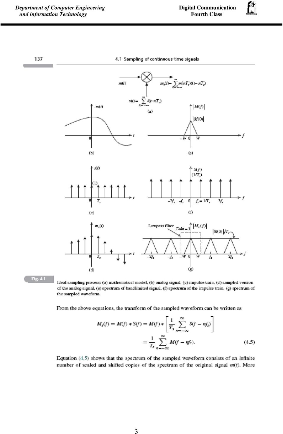
13 Quantization In all the sampling processes described in the previous section, the sampled signals are discrete in time but still continuous in amplitude. To obtain a fully digital representation of a continuous signal, two further operations are needed: quantization of the amplitude of the sampled signal and encoding of the quantized values, as illustrated in Figure below. m(nts) of a message signal m(t) at time t = nts into a discrete amplitude mˆ (nts) taken from a finite set of possible amplitudes. Clearly, if the finite set of amplitudes is chosen such that the spacing between two adjacent amplitude levels is sufficiently small, then the approximated (or quantized) signal, mˆ (nts). This implies that it is not possible to completely recover the sampled signal from the quantized signal. Assume that the quantization process is memoryless and instantaneous, meaning that the quantization of sample value at time t = nts is independent of earlier or later samples. With 13
 signal, mˆ (nts).")
14 this assumption, the quantization process can be described as in Figure 4.8. Let the amplitude range of the continuous signal be partitioned into L intervals Dl and Dl+1: Il : {Dl < m Dl+1}, l = 1,..., L. (4.18) Then the quantizer represents all the signal amplitudes in the interval Il by some amplitude Tl Il referred to as the target level (also known as the representation level or reconstruction level). The spacing between two adjacent decision levels is called the step-size. If the step-size is the same for each interval, then the quantizer is called a uniform quantizer, otherwise the quantizer is nonuniform. The uniform quantizer is the simplest and most practical one. Besides having equal decision intervals, the target level is chosen to lie in the middle of the interval From the description of the quantizer, it follows that the input output characteristic of the quantizer (or quantizer characteristic) is a staircase function. Figures 4.9(a) and 4.9(b) display two uniform quantizer characteristics, called midtread and midrise. For both characteristics, the decision levels are equally spaced and the lth target level is the midpoint of the lth interval, i.e., Tl =( D l + D l+1 )/2 14

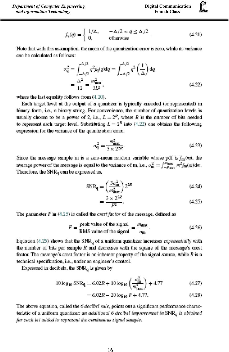
15 Uniform Quantization SNR The performance of a quantizer is usually evaluated in terms of its SNR. In what follows, this parameter is derived for the uniform quantizer. Typically, the input of the quantizer can be modeled as a zero-mean random variable m with some PDF f m (m). Furthermore, assume that the amplitude range of m is m max m m max, that the uniform quantizer is of midrise type, and that the number of quantization levels is L. Then the quantization step-size is given by = 2m max /L Let q = m mˆ be the error introduced by the quantizer, then - /2 q /2. If the step-size is sufficiently small (i.e., the number of quantization intervals L is sufficiently large), then it is reasonable to assume that the quantization error q is a uniform randomvariable over the range [ /2, /2]. The pdf of the random variable q is therefore given by 15
, then it is reasonable to assume that the quantization error q is a uniform randomvariable over the range [ /2, /2].")
16 16
17 Nonuniform Quantizers Consider a general compression characteristic as shown in Figure below where g(m) maps the interval [ m max,m max ] into the interval [ y max, y max ]. Note that the output of the compressor is uniformly quantized. Let yl and denote, respectively, the target level and the (equal) step-size of the lth quantization region for the compressed signal y. Recall that for an L-level midrise quantizer one has = 2y max /L. The corresponding target level and step-size of the lth region for the original signal m are ml and _l respectively. 4.4 Pulse-code modulation (PCM) The last block in Figure below to be discussed is the encoder. A PCM signal is obtained from the quantized PAM signal by encoding each quantized sample to a digital codeword. If the PAM signals are quantized using L target levels, then in binary PCM each quantized sample is digitally encoded into an R-bit binary codeword, where R = [log 2 L] + 1. The quantizing and encoding operations are usually performed in the same circuit known as an A/D converter. The advantage of having a PCM signal over a quantized PAM signal is that the binary digits of a PCM signal can 17
 The last block in Figure below to be discussed is the encoder.")
18 be transmitted using many efficient modulation schemes compared to the transmission of a PAM signal. There are several ways to establish a one-toone correspondence between target levels and the codeword. A convenient method, known as Natural Binary Coding (NBC), is to express the ordinal number of the target level as a binary number as described in Figure Another popular mapping method is called Gray Mapping. Gray mapping is important in the demodulation of the signal because the most likely errors caused by noise involve the erroneous selection of a target level that is adjacent to the transmitted target level. Still another mapping, called Foldover Binary Coding (FBC), is also sometimes encountered. Q) Write the Binary codeword of 16 level quantization ( 4 bit PCM encoder) using NBC, Gray Mapping, and FBC coding methods 18

19 The PCM Bandwidth and Bit Rate The sampling time T S is divided into equal space call T b bit time in this space the bit represented by an electrical shape TS Tb = R R : number of bit / sample The transmitted bandwidth and it rate are BW BW PCM PCM 1 2T b Log 2 ( L) 2T 1 Bit Rate = T b S = R Hz f S bit / sec Example/ SOL/ 1-2 mmax 2 *1 L = = = 2 level 1 ln( L) R = log 2 ( L) = = 1 bit ln(2) 2-2 = L = 2 R m L max mmax = 1 volt R = 8 L = *1 = = volt This solution repeated for other case 19
 = = 1 bit ln(2) 2-2 = L = 2 R m L max mmax = 1 volt R = 8 L = 256 2 *1 = = 0.")
20 Example/ Sol/ a) f s = 2f m f s =8000 Hz bit Rate = R f S bit Rate = 8*8000=64000 bit/sec MAX. recording Time= total memory size/bit rate MAX. recording Time=10 9 *8/64000 = sec = 2083 min and 20sec = 34 Hour, 43 min, and 20 sec b) f s = 2f m f s = Hz bit Rate = R f S bit Rate = 16*44000= bit/sec MAX. recording Time= total memory size/bit rate MAX. recording Time=10 9 *8/ = sec = 189 min and 23.6 sec = 3 Hour, 9 min, and 23.6 sec 20

21 c) f s = 2f m f s = 10 MHz bit Rate = R f S bit Rate = 12*10*10 6 =120 Mbit/sec bit Rate = 16*44000= bit/sec ( Video) (Sound) total bit/sec= 120* *10 6 = *10 6 bit/sec MAX. recording Time= total memory size/bit rate MAX. recording Time=10 9 *8/( *10 6 )= sec d) pixel bit fram Rate = * * fram pixel sec Rate = 1024*768*(8) *1 Rate = bit / sec = 1 min, and 6.28 sec MAX. recording Time=10 9 *8/( )= sec Example/ The PCM modulator have resolution ± 1% used to transmit binary data the analog signal have max, frequency 3 khz and sampling frequency is 2.5 time the analog frequency. Calculate PCM modulator parameters SOL/ Analog 3KHz Sample fs Quantizer L, SNR q Coder R Binary BW PCM Bit Rate fs = 2.5 f m fs = 7.5 KHz L = 1/(resolution) 21
22 L=1/.02 = 50 level R=log 2 (L) =ln(l)/ln(2) = bit R = 6 bit/sample 1 Let the input is sin or cos then F = 2 SNR q (db) = 6.02*R -20*log(F) +4.77= 43.9 db 1 BWPCM = Hz 2Tb Log 2 ( L) R f S BWPCM = = 2TS 2 1 Bit Rate = = R f S = 45 T b = 6 * 7500 = 22.5KHz 2 Kbit / sec Statistical Averages or Joint Moments As in the case of random variables, statistical averages or expected values can provide a partial but useful characterization for a random process. Consider N random variables x(t1), x(t2),..., x(tn). The most general form for the joint moments of these random variables is Mean value or the first moment: The mean value of the process at time t is Note that the average is across the ensemble and if the PDF varies with time, then the mean value is a (deterministic) function of time. If, however, the process is stationary, then the mean is independent of t or a constant, i.e., 22
23 Mean-squared value or the second moment: This is defined, as per the discussion for random variables as the variance: The physical interpretations of these moments are DC value (m x ), total power (MSV x ), AC power (σ 2 x ), and DC power (m 2 x). Q/ The statistic variable moments equation f(x)=x 2. Find the DC value (m x ), total power (MSV x ), AC power (σ 2 x ), and DC power (m 2 x). 3.5 The Gaussian Random Variable and Process Unquestionably the Gaussian PDF model is the one most frequently encountered in nature. This, as mentioned earlier, is because most random phenomena are due to the action of many different factors. By the central limit theorem, the resultant random variable tends to be Gaussian regardless of the underlying probabilities of the individual actors. A sample function is shown in Figure (1-a), along with the experimentally determined histogram in Figure (1-b). The histogram is an estimate of the 23
24 amplitude s PDF and we attempt to determine a reasonable analytical model for the PDF. The Gaussian PDF in the standard form in which one always sees it written. Of course f x (x) should be a valid PDF. This means that it needs to satisfy the two basic conditions: (i) f x (x) 0 for all x and (ii). 24
25 25
26 26
27 27
28 28
29 29
30 30
31 31
32 32
33 33
34 34
35 35
36 36
37 Example/ The low pass signal of max. frequency 3.3KHz sampled 8 KHz and code by eight bit/ sample transmit by QPSK with E b /N 0 =6dB. Calculate 1- total transmit bit rate Transmit bit rate = (R*f S )/2 Transmit bit rate = (8*8000)/2=32 Kbit/sec 2- probability of error P e = Q((2E b /N 0 ) 0.5 ) E b /N 0 (db)=10 Log(E b /N 0 ) E b /N 0 = 10 (6/10) = P e = Q(2.2817) P e =(1/2)*erfc(2.2817/2 0.5 )=
38 38
39 39
40 40
41 41
42 42
43 Code-Division Multiple Access (CDMA) In the context of communication engineering the appropriate statement is: You can use some of the bandwidth all of the time (FDMA), all of the bandwidth some of the time (TDMA), and you can also use all of the bandwidth all of the time (CDMA). Multiple access schemes can be classified into three broad categories. 1- Perhaps the earliest multiple access scheme was frequency-division multiple access (FDMA) in which each user is assigned a frequency band. The assigned bands typically do not overlap and the users transmit their messages simultaneously in time but over disjoint frequency bands. Commercial AM and FM radio, and television are classical examples of 43
44 this multiple access scheme as well as the first generation of mobile communications known as Advanced Mobile Phone System (AMPS). 2-In the second generation of mobile communication as exemplified by the GSM standard, time-division multiple access (TDMA) is used. Users now occupy the same frequency band simultaneously but send their messages in different time slots. 3-CDMA is different from the above in that users now occupy the same frequency band and transmit/receive simultaneously in time. Different users are separated or distinguished by distinct codes assigned to them. applications the called third generations of mobile communications have adopted CDMA as the multiple access scheme. 44
45 45
46 46
47 47
Voice---is analog in character and moves in the form of waves. 3-important wave-characteristics:
 Voice Transmission --Basic Concepts-- Voice---is analog in character and moves in the form of waves. 3-important wave-characteristics: Amplitude Frequency Phase Voice Digitization in the POTS Traditional
Sampling Theorem Notes. Recall: That a time sampled signal is like taking a snap shot or picture of signal periodically.
 Sampling Theorem We will show that a band limited signal can be reconstructed exactly from its discrete time samples. Recall: That a time sampled signal is like taking a snap shot or picture of signal
Digital Transmission of Analog Data: PCM and Delta Modulation
 Digital Transmission of Analog Data: PCM and Delta Modulation Required reading: Garcia 3.3.2 and 3.3.3 CSE 323, Fall 200 Instructor: N. Vlajic Digital Transmission of Analog Data 2 Digitization process
TCOM 370 NOTES 99-6 VOICE DIGITIZATION AND VOICE/DATA INTEGRATION
 TCOM 370 NOTES 99-6 VOICE DIGITIZATION AND VOICE/DATA INTEGRATION (Please read appropriate parts of Section 2.5.2 in book) 1. VOICE DIGITIZATION IN THE PSTN The frequencies contained in telephone-quality
How To Encode Data From A Signal To A Signal (Wired) To A Bitcode (Wired Or Coaxial)
 To A Bitcode (Wired Or Coaxial)") Physical Layer Part 2 Data Encoding Techniques Networks: Data Encoding 1 Analog and Digital Transmissions Figure 2-23.The use of both analog and digital transmissions for a computer to computer call. Conversion
Physical Layer Part 2 Data Encoding Techniques Networks: Data Encoding 1 Analog and Digital Transmissions Figure 2-23.The use of both analog and digital transmissions for a computer to computer call. Conversion
INTRODUCTION TO COMMUNICATION SYSTEMS AND TRANSMISSION MEDIA
 COMM.ENG INTRODUCTION TO COMMUNICATION SYSTEMS AND TRANSMISSION MEDIA 9/6/2014 LECTURES 1 Objectives To give a background on Communication system components and channels (media) A distinction between analogue
MODULATION Systems (part 1)
") Technologies and Services on Digital Broadcasting (8) MODULATION Systems (part ) "Technologies and Services of Digital Broadcasting" (in Japanese, ISBN4-339-62-2) is published by CORONA publishing co.,
Technologies and Services on Digital Broadcasting (8) MODULATION Systems (part ) "Technologies and Services of Digital Broadcasting" (in Japanese, ISBN4-339-62-2) is published by CORONA publishing co.,
Implementation of Digital Signal Processing: Some Background on GFSK Modulation
 Implementation of Digital Signal Processing: Some Background on GFSK Modulation Sabih H. Gerez University of Twente, Department of Electrical Engineering [email protected] Version 4 (February 7, 2013)
PCM Encoding and Decoding:
 PCM Encoding and Decoding: Aim: Introduction to PCM encoding and decoding. Introduction: PCM Encoding: The input to the PCM ENCODER module is an analog message. This must be constrained to a defined bandwidth
EECC694 - Shaaban. Transmission Channel
 The Physical Layer: Data Transmission Basics Encode data as energy at the data (information) source and transmit the encoded energy using transmitter hardware: Possible Energy Forms: Electrical, light,
Department of Electrical and Computer Engineering Ben-Gurion University of the Negev. LAB 1 - Introduction to USRP
 Department of Electrical and Computer Engineering Ben-Gurion University of the Negev LAB 1 - Introduction to USRP - 1-1 Introduction In this lab you will use software reconfigurable RF hardware from National
Solution. (Chapters 5-6-7-8) Dr. Hasan Qunoo. The Islamic University of Gaza. Faculty of Engineering. Computer Engineering Department
 Dr. Hasan Qunoo. The Islamic University of Gaza. Faculty of Engineering. Computer Engineering Department") The Islamic University of Gaza Faculty of Engineering Computer Engineering Department Data Communications ECOM 4314 Solution (Chapters 5-6-7-8) Dr. Hasan Qunoo Eng. Wafaa Audah Eng. Waleed Mousa 1. A cable
The Islamic University of Gaza Faculty of Engineering Computer Engineering Department Data Communications ECOM 4314 Solution (Chapters 5-6-7-8) Dr. Hasan Qunoo Eng. Wafaa Audah Eng. Waleed Mousa 1. A cable
Appendix C GSM System and Modulation Description
 C1 Appendix C GSM System and Modulation Description C1. Parameters included in the modelling In the modelling the number of mobiles and their positioning with respect to the wired device needs to be taken
(Refer Slide Time: 2:10)
") Data Communications Prof. A. Pal Department of Computer Science & Engineering Indian Institute of Technology, Kharagpur Lecture-12 Multiplexer Applications-1 Hello and welcome to today s lecture on multiplexer
Data Communications Prof. A. Pal Department of Computer Science & Engineering Indian Institute of Technology, Kharagpur Lecture-12 Multiplexer Applications-1 Hello and welcome to today s lecture on multiplexer
Spike-Based Sensing and Processing: What are spikes good for? John G. Harris Electrical and Computer Engineering Dept
 Spike-Based Sensing and Processing: What are spikes good for? John G. Harris Electrical and Computer Engineering Dept ONR NEURO-SILICON WORKSHOP, AUG 1-2, 2006 Take Home Messages Introduce integrate-and-fire
TCOM 370 NOTES 99-4 BANDWIDTH, FREQUENCY RESPONSE, AND CAPACITY OF COMMUNICATION LINKS
 TCOM 370 NOTES 99-4 BANDWIDTH, FREQUENCY RESPONSE, AND CAPACITY OF COMMUNICATION LINKS 1. Bandwidth: The bandwidth of a communication link, or in general any system, was loosely defined as the width of
Objectives. Lecture 4. How do computers communicate? How do computers communicate? Local asynchronous communication. How do computers communicate?
 Lecture 4 Continuation of transmission basics Chapter 3, pages 75-96 Dave Novak School of Business University of Vermont Objectives Line coding Modulation AM, FM, Phase Shift Multiplexing FDM, TDM, WDM
Computer Networks and Internets, 5e Chapter 6 Information Sources and Signals. Introduction
 Computer Networks and Internets, 5e Chapter 6 Information Sources and Signals Modified from the lecture slides of Lami Kaya ([email protected]) for use CECS 474, Fall 2008. 2009 Pearson Education Inc., Upper
Implementing Digital Wireless Systems. And an FCC update
 Implementing Digital Wireless Systems And an FCC update Spectrum Repacking Here We Go Again: The FCC is reallocating 600 MHz Frequencies for Wireless Mics 30-45 MHz (8-m HF) 174-250 MHz (VHF) 450-960 MHz
5 Signal Design for Bandlimited Channels
 225 5 Signal Design for Bandlimited Channels So far, we have not imposed any bandwidth constraints on the transmitted passband signal, or equivalently, on the transmitted baseband signal s b (t) I[k]g
Physical Layer, Part 2 Digital Transmissions and Multiplexing
 Physical Layer, Part 2 Digital Transmissions and Multiplexing These slides are created by Dr. Yih Huang of George Mason University. Students registered in Dr. Huang's courses at GMU can make a single machine-readable
Analog Representations of Sound
 Analog Representations of Sound Magnified phonograph grooves, viewed from above: The shape of the grooves encodes the continuously varying audio signal. Analog to Digital Recording Chain ADC Microphone
Non-Data Aided Carrier Offset Compensation for SDR Implementation
 Non-Data Aided Carrier Offset Compensation for SDR Implementation Anders Riis Jensen 1, Niels Terp Kjeldgaard Jørgensen 1 Kim Laugesen 1, Yannick Le Moullec 1,2 1 Department of Electronic Systems, 2 Center
Electronic Communications Committee (ECC) within the European Conference of Postal and Telecommunications Administrations (CEPT)
 within the European Conference of Postal and Telecommunications Administrations (CEPT)") Page 1 Electronic Communications Committee (ECC) within the European Conference of Postal and Telecommunications Administrations (CEPT) ECC RECOMMENDATION (06)01 Bandwidth measurements using FFT techniques
Page 1 Electronic Communications Committee (ECC) within the European Conference of Postal and Telecommunications Administrations (CEPT) ECC RECOMMENDATION (06)01 Bandwidth measurements using FFT techniques
1 Multi-channel frequency division multiplex frequency modulation (FDM-FM) emissions
 emissions") Rec. ITU-R SM.853-1 1 RECOMMENDATION ITU-R SM.853-1 NECESSARY BANDWIDTH (Question ITU-R 77/1) Rec. ITU-R SM.853-1 (1992-1997) The ITU Radiocommunication Assembly, considering a) that the concept of necessary
Rec. ITU-R SM.853-1 1 RECOMMENDATION ITU-R SM.853-1 NECESSARY BANDWIDTH (Question ITU-R 77/1) Rec. ITU-R SM.853-1 (1992-1997) The ITU Radiocommunication Assembly, considering a) that the concept of necessary
TUTORIAL FOR CHAPTER 8
 TUTORIAL FOR CHAPTER 8 PROBLEM 1) The informaiton in four analog signals is to be multiplexed and transmitted over a telephone channel that has a 400 to 3100 Hz bandpass. Each of the analog baseband signals
CS263: Wireless Communications and Sensor Networks
 CS263: Wireless Communications and Sensor Networks Matt Welsh Lecture 4: Medium Access Control October 5, 2004 2004 Matt Welsh Harvard University 1 Today's Lecture Medium Access Control Schemes: FDMA TDMA
Sol: Optical range from λ 1 to λ 1 +Δλ contains bandwidth
 1. Use Figure 3.47 and Figure 3.50 to explain why the bandwidth of twisted-wire pairs and coaxial cable decreases with distance. Figure 3.47 figure 3.50 sol: The bandwidth is the range of frequencies where
Digital Transmission (Line Coding)
") Digital Transmission (Line Coding) Pulse Transmission Source Multiplexer Line Coder Line Coding: Output of the multiplexer (TDM) is coded into electrical pulses or waveforms for the purpose of transmission
Digital Transmission (Line Coding) Pulse Transmission Source Multiplexer Line Coder Line Coding: Output of the multiplexer (TDM) is coded into electrical pulses or waveforms for the purpose of transmission
Digital Baseband Modulation
 Digital Baseband Modulation Later Outline Baseband & Bandpass Waveforms Baseband & Bandpass Waveforms, Modulation A Communication System Dig. Baseband Modulators (Line Coders) Sequence of bits are modulated
Chapter 6 Bandwidth Utilization: Multiplexing and Spreading 6.1
 Chapter 6 Bandwidth Utilization: Multiplexing and Spreading 6.1 Copyright The McGraw-Hill Companies, Inc. Permission required for reproduction or display. Note Bandwidth utilization is the wise use of
Lab 5 Getting started with analog-digital conversion
 Lab 5 Getting started with analog-digital conversion Achievements in this experiment Practical knowledge of coding of an analog signal into a train of digital codewords in binary format using pulse code
Communication Systems
 AM/FM Receiver Communication Systems We have studied the basic blocks o any communication system Modulator Demodulator Modulation Schemes: Linear Modulation (DSB, AM, SSB, VSB) Angle Modulation (FM, PM)
Taking the Mystery out of the Infamous Formula, "SNR = 6.02N + 1.76dB," and Why You Should Care. by Walt Kester
 ITRODUCTIO Taking the Mystery out of the Infamous Formula, "SR = 6.0 + 1.76dB," and Why You Should Care by Walt Kester MT-001 TUTORIAL You don't have to deal with ADCs or DACs for long before running across
DT3: RF On/Off Remote Control Technology. Rodney Singleton Joe Larsen Luis Garcia Rafael Ocampo Mike Moulton Eric Hatch
 DT3: RF On/Off Remote Control Technology Rodney Singleton Joe Larsen Luis Garcia Rafael Ocampo Mike Moulton Eric Hatch Agenda Radio Frequency Overview Frequency Selection Signals Methods Modulation Methods
The Phase Modulator In NBFM Voice Communication Systems
 The Phase Modulator In NBFM Voice Communication Systems Virgil Leenerts 8 March 5 The phase modulator has been a point of discussion as to why it is used and not a frequency modulator in what are called
Multiplexing on Wireline Telephone Systems
 Multiplexing on Wireline Telephone Systems Isha Batra, Divya Raheja Information Technology, Dronacharya College of Engineering Farrukh Nagar, Gurgaon, India ABSTRACT- This Paper Outlines a research multiplexing
Experiment 3: Double Sideband Modulation (DSB)
") Experiment 3: Double Sideband Modulation (DSB) This experiment examines the characteristics of the double-sideband (DSB) linear modulation process. The demodulation is performed coherently and its strict
Experiment 3: Double Sideband Modulation (DSB) This experiment examines the characteristics of the double-sideband (DSB) linear modulation process. The demodulation is performed coherently and its strict
How To Understand The Theory Of Time Division Duplexing
 Multiple Access Techniques Dr. Francis LAU Dr. Francis CM Lau, Associate Professor, EIE, PolyU Content Introduction Frequency Division Multiple Access Time Division Multiple Access Code Division Multiple
Chap#5 (Data communication)
") Chap#5 (Data communication) Q#1: Define analog transmission. Normally, analog transmission refers to the transmission of analog signals using a band-pass channel. Baseband digital or analog signals are
Chap#5 (Data communication) Q#1: Define analog transmission. Normally, analog transmission refers to the transmission of analog signals using a band-pass channel. Baseband digital or analog signals are
Broadband Networks. Prof. Dr. Abhay Karandikar. Electrical Engineering Department. Indian Institute of Technology, Bombay. Lecture - 29.
 Broadband Networks Prof. Dr. Abhay Karandikar Electrical Engineering Department Indian Institute of Technology, Bombay Lecture - 29 Voice over IP So, today we will discuss about voice over IP and internet
1.264 Lecture 32. Telecom: Basic technology. Next class: Green chapter 4, 6, 7, 10. Exercise due before class
 1.264 Lecture 32 Telecom: Basic technology Next class: Green chapter 4, 6, 7, 10. Exercise due before class 1 Exercise 1 Communications at warehouse A warehouse scans its inventory with RFID readers that
What s The Difference Between Bit Rate And Baud Rate?
 What s The Difference Between Bit Rate And Baud Rate? Apr. 27, 2012 Lou Frenzel Electronic Design Serial-data speed is usually stated in terms of bit rate. However, another oftquoted measure of speed is
Next Generation of High Speed. Modems8
 Next Generation of High Speed Modems High Speed Modems. 1 Traditional Modems Assume both ends have Analog connection Analog signals are converted to Digital and back again. Limits transmission speed to
CHAPTER 8 MULTIPLEXING
 CHAPTER MULTIPLEXING 3 ANSWERS TO QUESTIONS.1 Multiplexing is cost-effective because the higher the data rate, the more cost-effective the transmission facility.. Interference is avoided under frequency
Introduction to FM-Stereo-RDS Modulation
 Introduction to FM-Stereo-RDS Modulation Ge, Liang Tan, EK Kelly, Joe Verigy, China Verigy, Singapore Verigy US 1. Introduction Frequency modulation (FM) has a long history of its application and is widely
VCO Phase noise. Characterizing Phase Noise
 VCO Phase noise Characterizing Phase Noise The term phase noise is widely used for describing short term random frequency fluctuations of a signal. Frequency stability is a measure of the degree to which
Analog vs. Digital Transmission
 Analog vs. Digital Transmission Compare at two levels: 1. Data continuous (audio) vs. discrete (text) 2. Signaling continuously varying electromagnetic wave vs. sequence of voltage pulses. Also Transmission
RF Measurements Using a Modular Digitizer
 RF Measurements Using a Modular Digitizer Modern modular digitizers, like the Spectrum M4i series PCIe digitizers, offer greater bandwidth and higher resolution at any given bandwidth than ever before.
AN1200.04. Application Note: FCC Regulations for ISM Band Devices: 902-928 MHz. FCC Regulations for ISM Band Devices: 902-928 MHz
 AN1200.04 Application Note: FCC Regulations for ISM Band Devices: Copyright Semtech 2006 1 of 15 www.semtech.com 1 Table of Contents 1 Table of Contents...2 1.1 Index of Figures...2 1.2 Index of Tables...2
CDMA TECHNOLOGY. Brief Working of CDMA
 CDMA TECHNOLOGY History of CDMA The Cellular Challenge The world's first cellular networks were introduced in the early 1980s, using analog radio transmission technologies such as AMPS (Advanced Mobile
Introduction to Receivers
 Introduction to Receivers Purpose: translate RF signals to baseband Shift frequency Amplify Filter Demodulate Why is this a challenge? Interference (selectivity, images and distortion) Large dynamic range
Fundamentals of Satellite Communications Part 3
 Fundamentals of Satellite Communications Part 3 Modulation Techniques used in Satellite Communication Howard Hausman December, 2009 Fundamentals of Satellite Communications Part 3 Modulation Techniques
BROADBAND AND HIGH SPEED NETWORKS
 BROADBAND AND HIGH SPEED NETWORKS INTRODUCTION TO MUTIPLEXING Multiplexing is the set of techniques that allows the simultaneous transmission of multiple signals across a single data link INTRODUCTION
Revision of Lecture Eighteen
 Revision of Lecture Eighteen Previous lecture has discussed equalisation using Viterbi algorithm: Note similarity with channel decoding using maximum likelihood sequence estimation principle It also discusses
1. (Ungraded) A noiseless 2-kHz channel is sampled every 5 ms. What is the maximum data rate?
 A noiseless 2-kHz channel is sampled every 5 ms. What is the maximum data rate?") Homework 2 Solution Guidelines CSC 401, Fall, 2011 1. (Ungraded) A noiseless 2-kHz channel is sampled every 5 ms. What is the maximum data rate? 1. In this problem, the channel being sampled gives us the
Homework 2 Solution Guidelines CSC 401, Fall, 2011 1. (Ungraded) A noiseless 2-kHz channel is sampled every 5 ms. What is the maximum data rate? 1. In this problem, the channel being sampled gives us the
EPL 657 Wireless Networks
 EPL 657 Wireless Networks Some fundamentals: Multiplexing / Multiple Access / Duplex Infrastructure vs Infrastructureless Panayiotis Kolios Recall: The big picture... Modulations: some basics 2 Multiplexing
Chap 4 Circuit-Switching Networks
 hap 4 ircuit-switching Networks Provide dedicated circuits between users Example: 1. telephone network: provides 64Kbps circuits for voice signals 64Kbps=8 k samples/sec * 8 bits/sample 2. transport network:
Channel Bandwidth, MHz. Symbol Rate, Msym/sec
 APPENDIXB Information in the following tables is from the DOCSIS and EuroDOCSIS Radio Frequency Interface Specification, and should be considered minimum recommended performance criteria for reliable data
Lezione 6 Communications Blockset
 Corso di Tecniche CAD per le Telecomunicazioni A.A. 2007-2008 Lezione 6 Communications Blockset Ing. Marco GALEAZZI 1 What Is Communications Blockset? Communications Blockset extends Simulink with a comprehensive
NRZ Bandwidth - HF Cutoff vs. SNR
 Application Note: HFAN-09.0. Rev.2; 04/08 NRZ Bandwidth - HF Cutoff vs. SNR Functional Diagrams Pin Configurations appear at end of data sheet. Functional Diagrams continued at end of data sheet. UCSP
Public Switched Telephone System
 Public Switched Telephone System Structure of the Telephone System The Local Loop: Modems, ADSL Structure of the Telephone System (a) Fully-interconnected network. (b) Centralized switch. (c) Two-level
Digital Modulation. David Tipper. Department of Information Science and Telecommunications University of Pittsburgh. Typical Communication System
 Digital Modulation David Tipper Associate Professor Department of Information Science and Telecommunications University of Pittsburgh http://www.tele.pitt.edu/tipper.html Typical Communication System Source
T = 1 f. Phase. Measure of relative position in time within a single period of a signal For a periodic signal f(t), phase is fractional part t p
, phase is fractional part t p") Data Transmission Concepts and terminology Transmission terminology Transmission from transmitter to receiver goes over some transmission medium using electromagnetic waves Guided media. Waves are guided
Data Transmission Concepts and terminology Transmission terminology Transmission from transmitter to receiver goes over some transmission medium using electromagnetic waves Guided media. Waves are guided
How To Use A Sound Card With A Subsonic Sound Card
 !"## $#!%!"# &"#' ( "#' )*! #+ #,# "##!$ -+./0 1" 1! 2"# # -&1!"#" (2345-&1 #$6.7 -&89$## ' 6! #* #!"#" +" 1##6$ "#+# #-& :1# # $ #$#;1)+#1#+
Introduction and Comparison of Common Videoconferencing Audio Protocols I. Digital Audio Principles
 Introduction and Comparison of Common Videoconferencing Audio Protocols I. Digital Audio Principles Sound is an energy wave with frequency and amplitude. Frequency maps the axis of time, and amplitude
Appendix D Digital Modulation and GMSK
 D1 Appendix D Digital Modulation and GMSK A brief introduction to digital modulation schemes is given, showing the logical development of GMSK from simpler schemes. GMSK is of interest since it is used
AM Receiver. Prelab. baseband
 AM Receiver Prelab In this experiment you will use what you learned in your previous lab sessions to make an AM receiver circuit. You will construct an envelope detector AM receiver. P1) Introduction One
MSB MODULATION DOUBLES CABLE TV CAPACITY Harold R. Walker and Bohdan Stryzak Pegasus Data Systems ( 5/12/06) [email protected]
 pegasusdat@aol.com") MSB MODULATION DOUBLES CABLE TV CAPACITY Harold R. Walker and Bohdan Stryzak Pegasus Data Systems ( 5/12/06) [email protected] Abstract: Ultra Narrow Band Modulation ( Minimum Sideband Modulation ) makes
MSB MODULATION DOUBLES CABLE TV CAPACITY Harold R. Walker and Bohdan Stryzak Pegasus Data Systems ( 5/12/06) [email protected] Abstract: Ultra Narrow Band Modulation ( Minimum Sideband Modulation ) makes
HD Radio FM Transmission System Specifications Rev. F August 24, 2011
 HD Radio FM Transmission System Specifications Rev. F August 24, 2011 SY_SSS_1026s TRADEMARKS HD Radio and the HD, HD Radio, and Arc logos are proprietary trademarks of ibiquity Digital Corporation. ibiquity,
Sampling and Interpolation. Yao Wang Polytechnic University, Brooklyn, NY11201
 Sampling and Interpolation Yao Wang Polytechnic University, Brooklyn, NY1121 http://eeweb.poly.edu/~yao Outline Basics of sampling and quantization A/D and D/A converters Sampling Nyquist sampling theorem
The front end of the receiver performs the frequency translation, channel selection and amplification of the signal.
 Many receivers must be capable of handling a very wide range of signal powers at the input while still producing the correct output. This must be done in the presence of noise and interference which occasionally
MATRIX TECHNICAL NOTES
 200 WOOD AVENUE, MIDDLESEX, NJ 08846 PHONE (732) 469-9510 FAX (732) 469-0418 MATRIX TECHNICAL NOTES MTN-107 TEST SETUP FOR THE MEASUREMENT OF X-MOD, CTB, AND CSO USING A MEAN SQUARE CIRCUIT AS A DETECTOR
USB 3.0 CDR Model White Paper Revision 0.5
 USB 3.0 CDR Model White Paper Revision 0.5 January 15, 2009 INTELLECTUAL PROPERTY DISCLAIMER THIS WHITE PAPER IS PROVIDED TO YOU AS IS WITH NO WARRANTIES WHATSOEVER, INCLUDING ANY WARRANTY OF MERCHANTABILITY,
A WEB BASED TRAINING MODULE FOR TEACHING DIGITAL COMMUNICATIONS
 A WEB BASED TRAINING MODULE FOR TEACHING DIGITAL COMMUNICATIONS Ali Kara 1, Cihangir Erdem 1, Mehmet Efe Ozbek 1, Nergiz Cagiltay 2, Elif Aydin 1 (1) Department of Electrical and Electronics Engineering,
DigiPoints Volume 1. Student Workbook. Module 4 Bandwidth Management
 Bandwidth Management Page 4.1 DigiPoints Volume 1 Module 4 Bandwidth Management Summary This module will cover Time Division Multiplexing (TDM). TDM technology allows many users to access a particular
Lecture 2 Outline. EE 179, Lecture 2, Handout #3. Information representation. Communication system block diagrams. Analog versus digital systems
 Lecture 2 Outline EE 179, Lecture 2, Handout #3 Information representation Communication system block diagrams Analog versus digital systems Performance metrics Data rate limits Next lecture: signals and
Software Defined Radio
 Software Defined Radio GNU Radio and the USRP Overview What is Software Defined Radio? Advantages of Software Defined Radio Traditional versus SDR Receivers SDR and the USRP Using GNU Radio Introduction
AN-756 APPLICATION NOTE One Technology Way P.O. Box 9106 Norwood, MA 02062-9106 Tel: 781/329-4700 Fax: 781/326-8703 www.analog.com
 APPLICATION NOTE One Technology Way P.O. Box 9106 Norwood, MA 02062-9106 Tel: 781/329-4700 Fax: 781/326-8703 www.analog.com Sampled Systems and the Effects of Clock Phase Noise and Jitter by Brad Brannon
Probability and Random Variables. Generation of random variables (r.v.)
") Probability and Random Variables Method for generating random variables with a specified probability distribution function. Gaussian And Markov Processes Characterization of Stationary Random Process Linearly
Probability and Random Variables Method for generating random variables with a specified probability distribution function. Gaussian And Markov Processes Characterization of Stationary Random Process Linearly
RFSPACE CLOUD-IQ #CONNECTED SOFTWARE DEFINED RADIO
 CLOUD-IQ #CONNECTED SOFTWARE DEFINED RADIO 1 - SPECIFICATIONS Cloud-IQ INTRODUCTION The Cloud-IQ is a high performance, direct sampling software radio with an ethernet interface. It offers outstanding
Introduction to Wireless Communications and Networks
 Introduction to Wireless Communications and Networks Tongtong Li Dept. Electrical and Computer Engineering East Lansing, MI 48824 [email protected] 1 Outline Overview of a Communication System Digital
Understand the effects of clock jitter and phase noise on sampled systems A s higher resolution data converters that can
 designfeature By Brad Brannon, Analog Devices Inc MUCH OF YOUR SYSTEM S PERFORMANCE DEPENDS ON JITTER SPECIFICATIONS, SO CAREFUL ASSESSMENT IS CRITICAL. Understand the effects of clock jitter and phase
8. Cellular Systems. 1. Bell System Technical Journal, Vol. 58, no. 1, Jan 1979. 2. R. Steele, Mobile Communications, Pentech House, 1992.
 8. Cellular Systems References 1. Bell System Technical Journal, Vol. 58, no. 1, Jan 1979. 2. R. Steele, Mobile Communications, Pentech House, 1992. 3. G. Calhoun, Digital Cellular Radio, Artech House,
Lecture 1: Introduction
 Mobile Data Networks Lecturer: Victor O.K. Li EEE Department Room: CYC601D Tel.: 857 845 Email: [email protected] Course home page: http://www.eee.hku.hk/courses.msc/ 1 Lecture 1: Introduction Mobile data
On the Traffic Capacity of Cellular Data Networks. 1 Introduction. T. Bonald 1,2, A. Proutière 1,2
 On the Traffic Capacity of Cellular Data Networks T. Bonald 1,2, A. Proutière 1,2 1 France Telecom Division R&D, 38-40 rue du Général Leclerc, 92794 Issy-les-Moulineaux, France {thomas.bonald, alexandre.proutiere}@francetelecom.com
GSM/EDGE Output RF Spectrum on the V93000 Joe Kelly and Max Seminario, Verigy
 GSM/EDGE Output RF Spectrum on the V93000 Joe Kelly and Max Seminario, Verigy Introduction A key transmitter measurement for GSM and EDGE is the Output RF Spectrum, or ORFS. The basis of this measurement
AM/FM/ϕM Measurement Demodulator FS-K7
 Data sheet Version 02.00 AM/FM/ϕM Measurement Demodulator FS-K7 July 2005 for the Analyzers FSQ/FSU/FSP and the Test Receivers ESCI/ESPI AM/FM/ϕM demodulator for measuring analog modulation parameters
www.aticourses.com Boost Your Skills with On-Site Courses Tailored to Your Needs
 Boost Your Skills with On-Site Courses Tailored to Your Needs www.aticourses.com The Applied Technology Institute specializes in training programs for technical professionals. Our courses keep you current
QAM Demodulation. Performance Conclusion. o o o o o. (Nyquist shaping, Clock & Carrier Recovery, AGC, Adaptive Equaliser) o o. Wireless Communications
 o o. Wireless Communications") 0 QAM Demodulation o o o o o Application area What is QAM? What are QAM Demodulation Functions? General block diagram of QAM demodulator Explanation of the main function (Nyquist shaping, Clock & Carrier
0 QAM Demodulation o o o o o Application area What is QAM? What are QAM Demodulation Functions? General block diagram of QAM demodulator Explanation of the main function (Nyquist shaping, Clock & Carrier
RECOMMENDATION ITU-R BO.786 *
 Rec. ITU-R BO.786 RECOMMENDATION ITU-R BO.786 * MUSE ** system for HDTV broadcasting-satellite services (Question ITU-R /) (992) The ITU Radiocommunication Assembly, considering a) that the MUSE system
Chapter 8 - Power Density Spectrum
 EE385 Class Notes 8/8/03 John Stensby Chapter 8 - Power Density Spectrum Let X(t) be a WSS random process. X(t) has an average power, given in watts, of E[X(t) ], a constant. his total average power is
Multiplexing. Multiplexing is the set of techniques that allows the simultaneous transmission of multiple signals across a single physical medium.
 Multiplexing Multiplexing is the set of techniques that allows the simultaneous transmission of multiple signals across a single physical medium. The following two factors in data communications lead to
Module 5. Broadcast Communication Networks. Version 2 CSE IIT, Kharagpur
 Module 5 Broadcast Communication Networks Lesson 9 Cellular Telephone Networks Specific Instructional Objectives At the end of this lesson, the student will be able to: Explain the operation of Cellular
The Effect of Network Cabling on Bit Error Rate Performance. By Paul Kish NORDX/CDT
 The Effect of Network Cabling on Bit Error Rate Performance By Paul Kish NORDX/CDT Table of Contents Introduction... 2 Probability of Causing Errors... 3 Noise Sources Contributing to Errors... 4 Bit Error
Data Transmission. Data Communications Model. CSE 3461 / 5461: Computer Networking & Internet Technologies. Presentation B
 CSE 3461 / 5461: Computer Networking & Internet Technologies Data Transmission Presentation B Kannan Srinivasan 08/30/2012 Data Communications Model Figure 1.2 Studying Assignment: 3.1-3.4, 4.1 Presentation
Application Note Noise Frequently Asked Questions
 : What is? is a random signal inherent in all physical components. It directly limits the detection and processing of all information. The common form of noise is white Gaussian due to the many random
Data Transmission via Modem. The Last Mile Problem. Modulation of Digital Signals. Modem Standards (CCITT)
") The Last Mile Problem LN, MN, WN how to connect private users at home to such networks? Problem of the last mile: somehow connect private homes to the public Internet without laying many new cables By
The Last Mile Problem LN, MN, WN how to connect private users at home to such networks? Problem of the last mile: somehow connect private homes to the public Internet without laying many new cables By
CARLETON UNIVERSITY Department of Systems and Computer Engineering. SYSC4700 Telecommunications Engineering Winter 2014. Term Exam 13 February 2014
 CARLETON UNIVERSITY Department of Systems and Computer Engineering SYSC4700 Telecommunications Engineering Winter 2014 Term Exam 13 February 2014 Duration: 75 minutes Instructions: 1. Closed-book exam
Introduction to Digital Audio
 Introduction to Digital Audio Before the development of high-speed, low-cost digital computers and analog-to-digital conversion circuits, all recording and manipulation of sound was done using analog techniques.