GENESIS COUPE(BK) >2010 > G 2.0 DOHC > Body Electrical System > Immobilizer System > Description and Operation
|
|
|
- Claude Lloyd
- 10 years ago
- Views:
Transcription
1 GENESIS COUPE(BK) >2010 > G 2.0 DOHC > Body Electrical System > Immobilizer System > Description and Operation Description The immobilizer system will disable the vehicle unless the proper ignition key is used, in addition to the currently available anti-theft systems such as car alarms, the immobilizer system aims to drastically reduce the rate of auto theft. 1. Encrypted SMARTRA type immobilizer A. The SMARTRA system consists of a passive challenge - response (mutual authentication)transponder located in the ignition key, an antenna coil, a encoded SMARTRA unit, an indicator light and the PCM(ECM). B. The SMARTRA communicates to the PCM(ECM) (Engine Control Module) via a dedicated communications line. Since the vehicle engine management system is able to control engine mobilization, it is the most suitable unit to control the SMARTRA. C. When the key is inserted in the ignition and turned to the ON position, the antenna coil sends power to the transponder in the ignition key. The transponder then sends a coded signal back through the SMARTRA unit to the PCM(ECM). D. If the proper key has been used, the PCM(ECM) will energize the fuel supply system. The immobilizer indicator light in the cluster will simultaneously come on for more than five seconds, indicating that the SMARTRA unit has recognized the code sent by the transponder. E. If the wrong key has been used and the code was not received or recognized by the PCM(ECM) the indicator light will continue blinking for about five seconds until the ignition switch is turned OFF. F. If it is necessary to rewrite the PCM(ECM) to learn a new key, the dealer needs the customer's vehicle, all its keys and the Hi-scan (pro) equipped with an immobilizer program card. Any key that is not learned during rewriting will no longer start the engine. G. The immobilizer system can store up to eight key codes. H. If the customer has lost his key, and cannot start the engine, contact Hyundai motor service station. Components Operations PCM (Power Train Control Module) 1. The PCM(ECM) (A) carries out a check of the ignition key using a special encryption algorithm, which is programmed into the transponder as well as the PCM(ECM) simultaneously. Only if the results are equal, the engine can be started. The data of all transponders, which are valid for the vehicle, are stored in the PCM(ECM). ERN (Encrypted Randorn Number) value between EMS and encrypted smartra unit is checked and the validity of coded key is decided by EMS.
transponder located in the ignition key, an antenna coil, a encoded SMARTRA unit, an indicator light and the")
2 ENCRYPTED SMARTRA unit (A) The SMARTRA carries out communication with the built-in transponder in the ignition key. This wireless communication runs on RF (Radio frequency of 125 khz). The SMARTRA is mounted behind of the crash pad close to center cross bar. The RF signal from the transponder, received by the antenna coil, is converted into messages for serial communication by the SMARTRA device. And, the received messages from the PCM(ECM) are converted into an RF signal, which is transmitted to the transponder by the antenna. The SMARTRA does not carry out the validity check of the transponder or the calculation of encryption algorithm. This device is only an advanced interface, which converts the RF data flow of the transponder into serial communication to the PCM(ECM) and vice versa. TRANSPONDER (Built-in keys) The transponder (A) has an advanced encryption algorithm. During the key teaching procedure, the transponder will be programmed with vehicle specific data. The vehicle specific data are written into the transponder memory. The write procedure is once only; therefore, the contents of the transponder can never be modified or changed. Antenna coil The antenna coil (A) has the following functions.
 are converted into an RF signal, which is transmitted to the transponder by the antenna.")
3 - The antenna coil supplies energy to the transponder. - The antenna coil receives signal from the transponder. - The antenna coil sends transponder signal to the SMARTRA. It is located directly in front of the steering handle lock.

4 GENESIS COUPE(BK) >2010 > G 2.0 DOHC > Body Electrical System > Immobilizer System > Repair procedures Replacement Problems And Replacement Parts: Problem Part set Scan tool required? All keys have been lost Blank key (4) YES Antenna coil unit does not work Antenna coil unit NO ECM does not work PCM(ECM) YES Ignition switch does not work Ignition switch with Antenna coil unit YES Unidentified vehicle specific data occurs Key, PCM(ECM) YES SMARTRA unit does not work SMARTRA unit YES Replacement Of Ecm And Smartra In case of a defective ECM, the unit has to be replaced with a "virgin" or "neutral" ECM. All keys have to be taught to the new ECM. Keys, which are not taught to the ECM, are invalid for the new ECM (Refer to key teaching procedure). The vehicle specific data have to be left unchanged due to the unique programming of transponder. In case of a defective SMARTRA, it needs teaching the smartra. A new SMARTRA device replaces the old one and smartra need teaching. 1. Things to remember before a replacement (PCM(ECM)) 2. Things to remember before a replacement (Keys & Additional registration)
.")
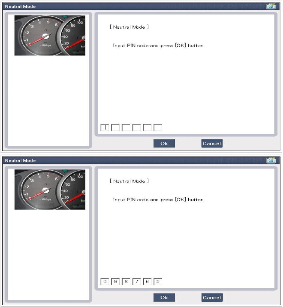
5 1. When there is only one key registered and you wish to register another key, you need to re-register the key which was already registered. 2. When the key #1 is registered and master key #2 is not registered, Put the key #1 in the IG/ON or the start position and remove it. The engine can be started with the unregistered key #2. (Note that key #2 must be used within 10 seconds of removing key #1) 3. When the key #1 is registered and key #2 is not registered, put the unregistered master key #2 in the IG/ON or the start position. The engine cannot be started even with the registered key #1. 4. When you inspect the immobilizer system, refer to the above paragraphs 1, 2 and 3. Always remember the 10 seconds zone. 5. If the pin code & password are entered incorrectly on three consecutive inputs, the system will be locked for one hour. 6. Be cautious not to overlap the transponder areas. 7. Problems can occur at key registration or vehicle starting if the transponders should overlap. Neutralizing Of ECM The PCM(ECM) can be set to the "neutral" status by a tester. A valid ignition key is inserted and after ignition on is recorded, the PCM(ECM) requests the vehicle specific data from the tester. The communication messages are described at "Neutral Mode" After successfully receiving the data, the PCM(ECM) is neutralized. The ECM remains locked. Neither the limp home mode nor the "twice ignition on" function, is accepted by the PCM(ECM). The teaching of keys follows the procedure described for the virgin PCM(ECM). The vehicle specific data have to be unchanged due to the unique programming of the transponder. If data should be changed, new keys with a virgin transponder are requested. This function is for neutralizing the PCM(ECM) and Key. Ex) when lost key, Neutralize the PCM(ECM) then teach keys. (Refer to the Things to do when Key & PIN Code the PCM(ECM) can be set to the "neutral" status by a scanner. If wrong vehicle specific data have been sent to SMATRA three times continuously or intermittently, the SMATRA will reject the request to enter neutral mode for one hour. Disconnecting the battery or other manipulation cannot reduce this time. After connecting the battery the timer starts again for one hour. Neutralizing setting condition - In case of PCM(ECM) status "Learnt" regardless of user password "Virgin or Learnt" - Input correct PIN code by scanner. - Neutralizing meaning. : PIN code (6) & user password (4) deletion. : Locking of ECM (except key teaching permission) Neutralizing meaning: - PIN Code(6) & User P/Word(4) deletion - Locking of EMS(except Key Learning permission)

6

7
8

9 Neutralizing Of SMARTRA The EMS can be set to the status "neutral" by tester Ignition key (regardless of key status) is inserted and after IGN ON. If receiving the correct vehicle password from GST, SMARTRA can be neutralized. The neutralization of SMARTRA is possible if DPN is same as the value inputted by GST. In case that the SMARTRA status is neutral, the EMS keeps the lock state. And the start is not possible by "twice ignition". In case of changing the vehicle password, new virgin transponder must be only used. And in case of virgin key, after Learning the key of vehicle password, it can be used. If wrong vehicle specific data have been sent to SMATRA three times continuously or intermittently, the SMATRA will reject the request to enter neutral mode for one hour. Disconnecting the battery or other manipulation cannot reduce this time. After connecting the battery the timer starts again for one hour. Neutralizing Setting condition : - In case of "SMARTRA status", "Learnt" - Input correct Pin code by tester Neutralizing meaning : - Vehicle password(dpn Code) & SEK Code deletion. - Permission of New DPN Learning.

10

11

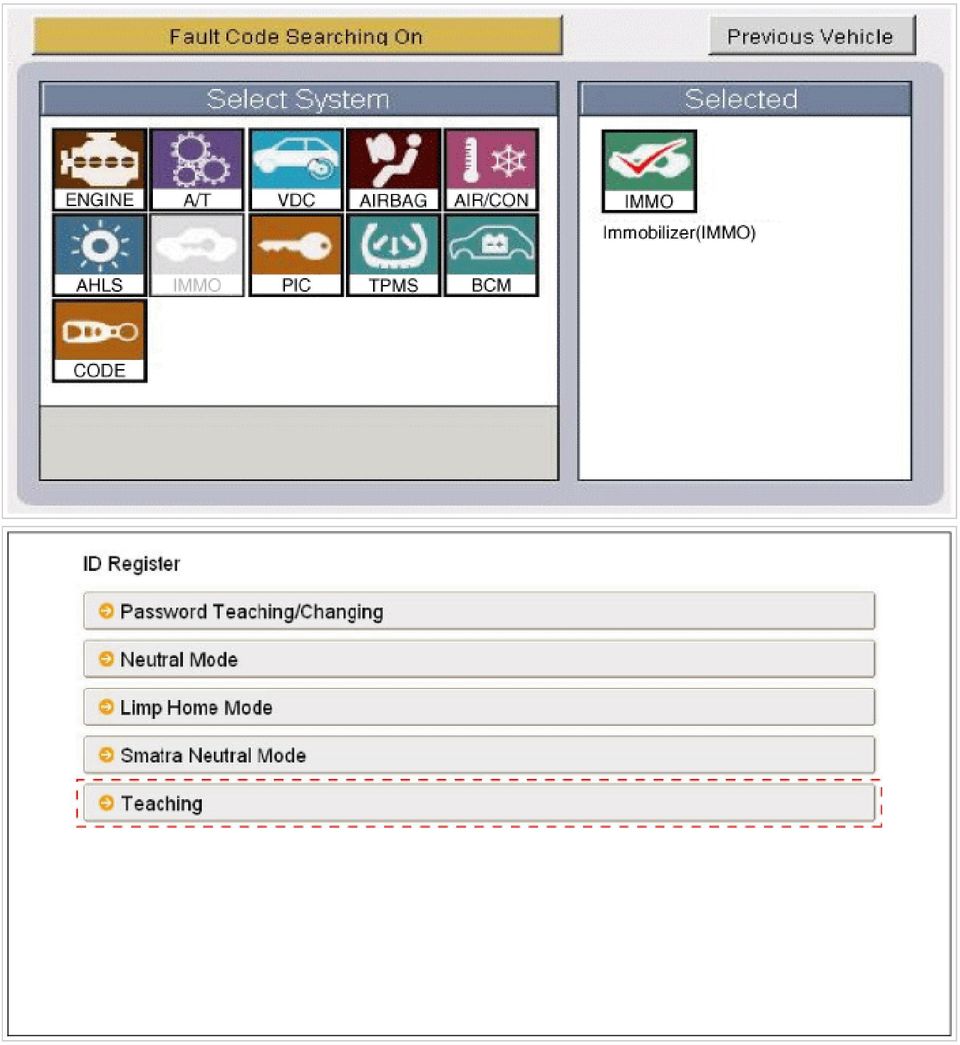
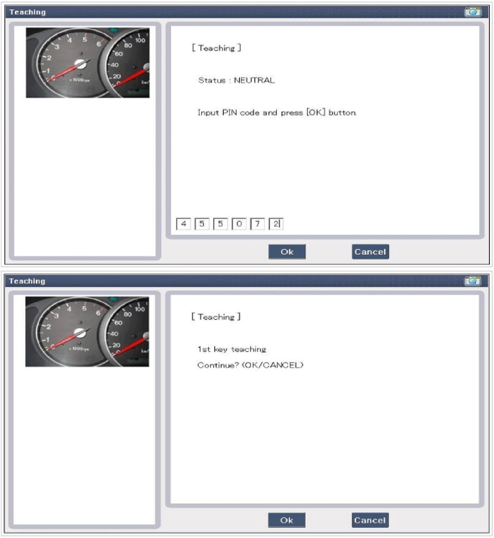
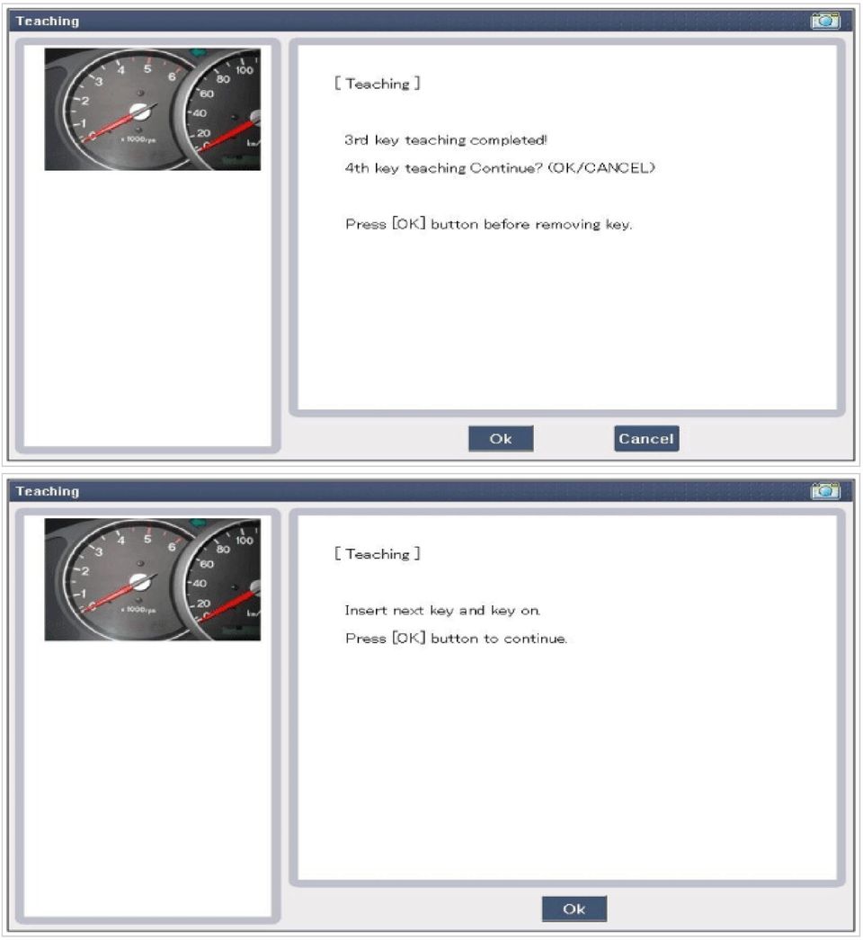
12 Teaching Procedures 1. Key Teaching Procedure Key teaching must be done after replacing a defective PCM(ECM) or when providing additional keys to the vehicle owner. The procedure starts with an PCM(ECM) request for vehicle specific data (PIN code: 6digits) from the tester. The "virgin" PCM (ECM) stores the vehicle specific data and the key teaching can be started. The "learnt" PCM(ECM) compares the vehicle specific data from the tester with the stored data. If the data are correct, the teaching can proceed. If incorrect vehicle specific data have been sent to the PCM(ECM) three times, the PCM(ECM) will reject the request of key teaching for one hour. This time cannot be reduced by disconnecting the battery or any other manipulation. After reconnecting the battery, the timer starts again for one hour. The key teaching is done by ignition on with the key and additional tester commands. The PCM(ECM) stores the relevant data in the EEPROM and in the transponder. Then the PCM(ECM) runs the authentication required for confirmation of the teaching process. The successful programming is then confirmed by a message to the tester. If the key is already known to the PCM(ECM) from a previous teaching, the authentication will be accepted and the EEPROM data are updated. There is no changed transponder content (this is impossible for a learnt transponder). The attempt to repeatedly teach a key, which has been taught already during the same teaching cycle, is recognized by the PCM(ECM). This rejects the key and a message is sent to the tester. The PCM(ECM) rejects invalid keys, which are presented for teaching. A message is sent to the tester. The key can be invalid due to faults in the transponder or other reasons, which result from unsuccessful programming of data. If the PCM(ECM) detects different authenticators of a transponder and an PCM(ECM), the key is considered to be invalid. The maximum number of taught keys is 8 If an error occurs during the Immobilizer Service Menu, the PCM(ECM) status remains unchanged and a specific fault code is stored. If the PCM(ECM) status and the key status do not match for teaching of keys, the tester procedure will be stopped and a
 three times, the PCM(ECM) will reject the request of key teaching for one hour.")
13 specific fault code will be stored at PCM(ECM). When teaching the 1st key, Smartra regists at the same time. (1) PCM(ECM) learnt status.

14
15
16

17

18
19 (2) PCM(ECM) virgin status. After replacing new "PCM(ECM)" scan tool displays that PCM(ECM) is virgin status in Key Teaching mode. "VIRGIN" status means that PCM(ECM) has not matched any PIN code before. Password Teaching/changing 1. User Password Teaching Procedure The user password for limp home is taught at the service station. The owner of the vehicle can select a number with four digits. The user password teaching is only accepted by a "learnt" PCM(ECM). Before first teaching of user password to an PCM (ECM), the status of the password is "virgin" No limp home function is possible. The teaching is started by ignition on, with a valid key(learnt key) and sending the user password by tester. After successful teaching, the status of the user password changes from "virgin" to "learnt" The learnt user password can also be changed. This can be done if the user password status is "learnt" and the tester sends authorization of access, either the old user password or the vehicle specific data. After correct authorization, the PCM(ECM) requests the new user password. The status remains "learnt" and the new user password will be valid for the next limp home mode. If wrong user passwords or wrong vehicle specific data have been sent to the PCM(ECM) three times continuously or intermittently, the PCM(ECM) will reject the request to change the password for one hour. This time cannot be reduced by disconnecting the battery or any other actions. After reconnecting the battery, the timer starts again for one hour. 2. User password teaching
. Before first teaching of user password to an PCM (ECM), the status of the password is \"virgin\" No limp home function is possible.")
20

21
22 In case of putting wrong password, retry from first step after 10 seconds. 3. User password changing
23
24
25 Limp Home Function 1. Limp Home By Tester If the PCM(ECM) detects the fault of the SMARTRA or transponder, the PCM(ECM) will allow limp home function of the immobilizer. Limp home is only possible if the user password (4 digits) has been given to the PCM(ECM) before. This password can be selected by the vehicle owner and is programmed at the service station. The user password can be sent to the PCM(ECM) via the special tester menu. Only if the PCM(ECM) is in status "learnt" and the user password status is "learnt" and the user password is correct, the PCM (ECM) will be unlocked for a period of time (30 sec.). The engine can only be started during this time. After the time has elapsed, engine start is not possible. If the wrong user password is sent, the PCM(ECM) will reject the request of limp home for one hour. Disconnecting the battery or any other action cannot reduce this time. After connecting the battery to the PCM(ECM), the timer starts again for one hour.
26
27 2. Limp Home By Ignition Key The limp home can be activated also by the ignition key. The user password can be input to the PCM(ECM) by a special sequence of ignition on/off. Only if the PCM(ECM) is in status "learnt" and the user password status is "learnt" and the user password is correct, the PCM (ECM) will be unlocked for a period of time (30 sec.). The engine can be started during this time. After the time has elapsed, engine start is not possible. After a new password has been input, the timer (30 sec.) will start again. After ignition off, the PCM(ECM) is locked if the timer has elapsed 8 seconds. For the next start, the input of the user password is requested again.
28
29 GENESIS COUPE(BK) >2010 > G 2.0 DOHC > Body Electrical System > Immobilizer System > Troubleshooting Diagnosis Of Immobilizer Faults - Communication between the ECM and the SMARTRA. - Function of the SMARTRA and the transponder. - Data (stored in the ECM related to the immobilizer function. The following table shows the assignment of immobilizer related faults to each type: Immobilizer Related Faults Fault types Diagnostic codes PCM(ECM) fault 1. Non-Immobilizer-EMS connected to an Immobilizer P1610 Transponder key fault Transponder key fault SMARTRA fault SMARTRA fault SMARTRA fault Antenna coil fault Immobilizer indicator lamp fault Transponder key fault PCM(ECM) fault PCM(ECM) internal permanent memory (EEPROM) fault Locked by timer 1. Transponder not in password mode 2. Transponder transport data has been changed. 1. Transponder programming error 1. Invalid message from SMARTRA to PCM(ECM) 1. Virgin SMARTRA at learnt EMS 2. Neutral SMARTRA at learnt EMS 3. Incorrect the Authentication of EMS and SMARTRA 4. Locking of SMARTRA 1. No response from SMARTRA 2. Antenna coil error 3. Communication line error (Open/Short etc.) 4. Invalid message from SMARTRA to PCM(ECM) 1. Antenna coil open/short circuit 1. Immobilizer indicator lamp error (Cluster) 1. Corrupted data from transponder 2. More than one transponder in the magnetic field (Antenna coil) 3. No transponder (Key without transponder) in the magnetic field (Antenna coil) 1. Request from PCM(ECM) is invalid (Protocol layer violation- Invalid request, check sum error etc.) 1. PCM(ECM) internal permanent memory (EEPROM) fault 2. Invalid write operation to permanent memory (EEPROM) 1. Exceeding the maximum limit of Twice IGN ON ( 32 times) P1674 (Transponder status error) P1675 (Transponder programming error) P1676 (SMARTRA message error) P169A (SMARTRA Authentication fail) P1690 (SMARTRA no response) P1691 (Antenna coil error) P1692 (Immobilizer lamp error) P1693 (Transponder no response error/invalid response) P1694 (PCM(ECM) message error) P1695 (PCM(ECM) memory error) P1699 (Twice IG ON over trial) Troubleshooting
30 NO DTC code Description 1 P1610 Non-Immobilizer-EMS Connected to an Immobilizer 2 P1674 Immobilizer-Transponder status Error 3 P1675 Immobilizer-Transponder Programming Error 4 P1676 Immobilizer-Smartra Message Error 5 P169A Immobilizer-SMARTRA Authentication Fail 6 P1690 Immobilizer-Smartra No Response 7 P1691 Immobilizer-Antenna Coil Error 8 P1692 Immobilizer Indicator Lamp Error 9 P1693 Immobilizer-Transponder Error 10 P1694 Immobilizer-EMS Message Error 11 P1695 Immobilizer-EMS Memory Error 12 P1696 Immobilizer-Authentication Fail 13 P1699 Immobilizer-Twice Overtrial
31 GENESIS COUPE(BK) >2010 > G 2.0 DOHC > Body Electrical System > Immobilizer System > P1610 Non- Immobilizer-EMS Connected to an Immobilizer General Description The immobilizer system consists of a passive challenge-response (mutual authentication) transponder inside the key head, the encoded SMARTRA3 unit /key and the EMS can decode the secret code stored in the SMARTRA3. The EMS carries out the immobilizer function, the SMATRA3 management and the key management. The immobilizer function is the unlocking of EMS only after detection of a valid ignition key /the SMATRA3 and the locking of EMS after switching off the engine. The EMS communicates the encoded messages to the SMARTRA3 via a dedicated communication line and confirms the key with the SMARTRA3. The EMS related to immobilizer has the 3 kinds of software. At the first IGN on, the EMS concludes the software of each option (smart key, non-encoded SMARTRA3, encoded SMARTRA3) by communication. It is called The autodection for EMS The EMS keeps the previous option before being neutral when it is setted to each option. DTC Description The PCM/ECM sets DTC P1610 if Non Immobilizer EMS is installed on vehicle equipped with Immobilizer. DTC Detecting Condition Item Detecting Condition Possible Cause DTC Strategy - Enable Conditions Threshold value Detecting time IG ON Non Immobilizer PCM/ECM connected Immediately Invalid PCM/ECM FAIL SAFE - Diagnostic Circuit Diagram
32 Monitor Scantool Data 1. Check status (1) IGN "ON" & Engine "OFF" (2) Monitor the "ECM Status" Parameter on the Scantool. Specification : 'LEARNT' Fig.1) This data show that 3 keys have been taught, ECU has been learnt, Key in key cylinder has been learnt and SMARTRA3 has been learnt (3) Has the ECM been learnt? Check connectors for looseness, poor connection, bending, corrosion, contamination, deterioration, or damage. Repair or replace as necessary and then go to "Verification of Vehicle Repair" procedure. Substitute with a ECM equipped with Immobilizer and perform the Key teaching procedure with scantool and check for proper operation.
33 If the problem is corrected, replace ECM and then go to "Verification of Vehicle Repair" procedure. If the EMS is only replaced using an existing key and SMARTRA3, after replacing the virgin or neutral EMS, reteaching is possible by key Learning mode of scanner. When the same PIN used in existing vehicle is only inputted, the SMARTRA3 Learning and key Learnings are possible. Verification of Vehicle Repair After a repair, it is essential to verify that the fault has been corrected. 1. Connect scantool and selet "Diagnostic Trouble Codes(DTCs)" mode and then clear DTC. 2. Operate the vehicle and monitor the DTC on the scantool. 3. Are any DTCs present? Go to the applicable troubleshooting procedure. System is performing to specification at this time.
34 GENESIS COUPE(BK) >2010 > G 2.0 DOHC > Body Electrical System > Immobilizer System > P1674 Immobilizer-Transponder status Error General Description The vehicle immobilizer system consists of the ECM, the SMARTRA3 and ignition keys with built-in transponder. The ECM carries out the check of ignition key by special encryption algorithm with SMARTRA3 and Transponder. The encryption algorithm (between ECM and SMARTRA3) is the one offered from BOSCH. The encryption algorithm (between ECM and Transponder) is Hitag type 2 which is a high level system. With IGN On, the ECM executes the key Authentication after SMARTRA3 authentication. The Engine can be started when the key authentication is confirmed by the SMARTRA3. The Key teaching procedure starts with ECM request of PIN from Scanner. The "virgin ECM stores the PIN and the key Learning can be started. The "learnt ECM compares the PIN from tester with the vehicle password in Transponder. If the data are correct, the key Learning can be started. Scanner requests the Learning of the first key, the SMARTRA3 is registered at first and then the first key is registered by ECM. If the SMARTRA3 status is learnt and PIN number is different, the SMARTRA3 will return the incorrect PIN data to the ECM. In this case,the ECM can t excute the key learning process. DTC Description The ECM sets DTC P1674 if transponder key that can't be register(transponder not in the password mode or whose transport data has been changed) is inserted for registration procedure. DTC Detecting Condition Item Detecting Condition Possible Cause DTC Strategy - Enable Conditions Threshold value Detecting time IG ON (On Registering TP Procedure) Key not in VIRGIN Status or with invalid ID code Immediately Invalid transponder. Key not in 'VIRGIN' Status or with invalid ID code FAIL SAFE - Diagnostic Circuit Diagram
35 Monitor Scantool Data 1. Check status (1) IGN "ON" & Engine "OFF" (2) Monitor the "ECM, Key and Smartra Status" Parameter on the Scantool. Specification : 'LEARNT' Fig.1) This data show that 3 keys have been taught, ECU has been learnt, Key in key cylinder has been learnt and SMARTRA3 has been learnt (3) Have both the ECM and KEY status been learnt? Substitute with known good "virgin" transponder and go to "Component Inspection" Procedure. Go to "Component Inspection" Procedure.
36 Component Inspection 1. Check transponder (1) IGN "ON" & Engine "OFF" (2) Neutralize ECM and Register transponder key by scantool. Pin code is requied to Neutralize ECM and to Register transponder key (3) Are Neutralizing and Registering completed normally? Check connectors for looseness, poor connection, bending, corrosion, contamination, deterioration, or damage. Repair or replace as necessary and then go to "Verification of Vehicle Repair" procedure. Substitute with a known-good transponder and perform key teaching procedure with scanner. If the problem is corrected, replace transponder and then go to "Verification of Vehicle Repair" procedure. Verification of Vehicle Repair After a repair, it is essential to verify that the fault has been corrected. 1. Connect scantool and selet "Diagnostic Trouble Codes(DTCs)" mode and then clear DTC. 2. Operate the vehicle and monitor the DTC on the scantool. 3. Are any DTCs present? Go to the applicable troubleshooting procedure. System is performing to specification at this time.
37 GENESIS COUPE(BK) >2010 > G 2.0 DOHC > Body Electrical System > Immobilizer System > P1675 Immobilizer-Transponder Programming Error General Description The vehicle immobilizer system consists of the ECM, the SMARTRA3 and ignition keys with built-in transponder. The ECM carries out the check of ignition key by special encryption algorithm with SMARTRA3 and Transponder. The encryption algorithm (between ECM and SMARTRA3) is the one offered from BOSCH. The encryption algorithm (between ECM and Transponder) is Hitag type 2 which is a high level system. With IGN On, the ECM executes the key Authentication after SMARTRA3 authentication. The Engine can be started when the key authentication is confirmed by the SMARTRA3. The Key teaching procedure starts with ECM request of PIN from Scanner. The "virgin ECM stores the PIN and the key Learning can be started. The "learnt ECM compares the PIN from tester with the vehicle password in Transponder. If the data are correct, the key Learning can be started. Scanner requests the Learning of the first key, the SMARTRA3 is registered at first and then the first key is registered by ECM. If the SMARTRA3 status is learnt and PIN number is different, the SMARTRA3 will return the incorrect PIN data to the ECM. In this case,the ECM can t excute the key learning process. DTC Description The ECM sets DTC P1675 if characteristic data of transponder doesn't coincide with that of ECM owing to transponder programming error. DTC Detecting Condition Item Detecting Condition Possible Cause DTC Strategy - Enable Conditions Threshold value Detecting time IG ON(During the authentification) Invalid characteristic data No transponder or more than two transponder is detected by coil antenna Immediately Invalid transponder. Invalid characteristic data No transponder or more than two transponder is detected by coil antenna FAIL SAFE - Diagnostic Circuit Diagram
38 Monitor Scantool Data 1. Check status (1) IGN "ON" & Engine "OFF" (2) Monitor the "ECM, Key and Smartra Status" Parameter on the Scantool. Specification : 'LEARNT' Fig.1) This data show that 3 keys have been taught, ECU has been learnt, Key in key cylinder has been learnt and SMARTRA3 has been learnt. (3) Are "KEY STATUS", "SMARTRA STATUS" and "ECU STATUS' Parameter within specifications? Check connectors for looseness, poor connection, bending, corrosion, contamination, deterioration, damage on the ECM or SMARTRA. And This DTC has not erased in previous repair. Repair or replace as necessary and then go to "Verification of Vehicle Repair" procedure. Go to "Component Inspection" Procedure.
39 Component Inspection 1. Check transponder (1) IGN "ON" & Engine "OFF" (2) Neutralize ECM and Register transponder key by scantool. Pin code is required to Neutralize ECM and to Register transponder key (3) Are Neutralizing and Registering completed normally? Check connectors for looseness, poor connection, bending, corrosion, contamination, deterioration, or damage. Repair or replace as necessary and then go to "Verification of Vehicle Repair" procedure. Substitute with a known-good transponder and perform the key teaching procedure with scanner. If the problem is corrected, replace transponder and then go to "Verification of Vehicle Repair" procedure. Verification of Vehicle Repair After a repair, it is essential to verify that the fault has been corrected. 1. Connect scantool and selet "Diagnostic Trouble Codes(DTCs)" mode and then clear DTC. 2. Operate the vehicle and monitor the DTC on the scantool. 3. Are any DTCs present? Go to the applicable troubleshooting procedure. System is performing to specification at this time.
40 GENESIS COUPE(BK) >2010 > G 2.0 DOHC > Body Electrical System > Immobilizer System > P1676 Immobilizer-Smartra Message Error General Description 1. The sequences of the PIN code storage are as follows. (1) Input the PIN code into the scanner when key teaching process. he scanner transmits the Encrypted Code to the ECM after converting the PIN code into Encrypted Code. (2) When the ECM gets the firtst key learning command, it transmits the SMARTRA3 learnt command and Encrypted Code to the SMARTRA3 (3) If the SMARTRA3 statue is virgin/neutral, the SMARTRA3 stores Encrypted Code in EEPROM and transmits the success message of the Encrypted Code storage. (If the SMARTRA3 is learnt, the SMARTRA3 compares Encrypted Code transmitted by the ECM with Encrypted Code stored in EEPROM and transmits the (in)correct Encrypted Code message to ECM) (4) If the SMARTRA3 is learnted normally or the Encrypted Code of the registered SMARTRA3 is the same as the ECM, the ECM begins operation the Transponder Learning. (5) If the learning of the first transponder, the ECM stores the Encrypted Code in its EEPROM and converts state into learnt state. 2. The SMARTRA3 learning : (1) starts with EMS request of PIN from scanner through the key teaching procedure. (2) is possible in case that the status of SMARTAR is virgin or neutral. (3) In case that the SMARTRA3 is learnt, the SMARTRA3 will transmits the information if PIN inputted from scanner is same as the PIN in SMARTRA3. (4) is possible regardless of key status. 3. The sequence of the SMARTRA3 confirms are as follows. (1) After communication with the SMARTRA3, the ECM transmits the random number with requirement of the TP ID information. (2) The SMARTRA3 encryptes the random number and transmits the result(encrypted Random Number) to the ECM with TP ID information. (3) The ECM compares the result transmitted from the SMARTRA3 with the result calculated by ECM. And If result are coincided with each other; the ECS concludes the valid confirmation of the SMARTRA3. DTC Description The ECM sets DTC P1676 if there's any fault in message from SMARTRA to ECU DTC Detecting Condition Item Detecting Condition Possible Cause DTC Strategy - Enable Conditions Threshold value Detecting time IG ON SMARTRA Message error Immediately Faulty SMARTRA FAIL SAFE - Diagnostic Circuit Diagram
41 Monitor Scantool Data 1. Check transponder and ECU status (1) IGN "ON" & Engine "OFF" (2) Monitor the "ECM, Key and Smartra Status" Parameter on the Scantool. Specification : 'LEARNT' Fig.1) This data show that 3 keys have been taught, ECU has been learnt, the Key in key cylinder has been learnt and SMARTRA3 has been learnt (3) Has the "Smartra STATUS" been learnt? Check connectors for looseness, poor connection, bending, corrosion, contamination, deterioration, damage on the ECM or SMARTRA. And this DTC has not erased in previous repair. Repair or replace as necessary and then go to "Verification of Vehicle Repair" procedure. Go to "Component Inspection" Procedure.
42 Component Inspection 1. Check SMARTRA (1) IGN "ON" & Engine "OFF" (2) Neutralize SMARTRA with scantool. (3) Neutralize ECM and Register transponder key by scantool. Pin code is required to Neutralize SMARTRA & ECM and to Register transponder key (4) Are Neutralizing and Registering Key completed normally? Check connectors for looseness, poor connection, bending, corrosion, contamination, deterioration, damage on the ECM or SMARTRA. Or It has not erased this DTC in previous repair. Repair or replace as necessary and then go to "Verification of Vehicle Repair" procedure. Substitute with a known-good SMARTRA and perform the Key teaching. If the problem is corrected, replace SMARTRA and then go to "Verification of Vehicle Repair" procedure. If the SMARTRA3 is only replaced using an existing key and ECM, after replacing the virgin or "neutral SMARTRA3, reteaching is possible by key Learning mode of GDS. In this case, all existing key must be retaught. If SMATRA3 is replaced to another one (used at other vehicle), it can only recycle its neutralized first before replacing. Verification of Vehicle Repair After a repair, it is essential to verify that the fault has been corrected. 1. Connect scantool and selet "Diagnostic Trouble Codes(DTCs)" mode and then clear DTC. 2. Operate the vehicle and monitor the DTC on the scantool. 3. Are any DTCs present? Go to the applicable troubleshooting procedure. System is performing to specification at this time.
43 GENESIS COUPE(BK) >2010 > G 2.0 DOHC > Body Electrical System > Immobilizer System > P169A Immobilizer-SMARTRA Authentication Fail General Description 1. The sequences of the PIN code storage are as follows. (1) Input the PIN code into the scanner when key teaching process. The scanner transmits the Encrypted Code to the ECM after converting the PIN code into Encrypted Code. (2) When the ECM gets the firtst key learning command, it transmits the SMARTRA3 learnt command and Encrypted Code to the SMARTRA3 (3) If the SMARTRA3 statue is virgin/neutral, the SMARTRA3 stores Encrypted Code in EEPROM and transmits the success message of the Encrypted Code storage. (If the SMARTRA3 is learnt, the SMARTRA3 compares Encrypted Code transmitted by the ECM with Encrypted Code stored in EEPROM and transmits the (in)correct Encrypted Code message to ECM) (4) If the SMARTRA3 is learnted normally or the Encrypted Code of the registered SMARTRA3 is the same as the ECM, the ECM begins operation the Transponder Learning. (5) If the learning of the first transponder, the ECM stores the Encrypted Code in its EEPROM and converts state into learnt state. 2. The SMARTRA3 learning : (1) starts with EMS request of PIN from scanner through the key teaching procedure. (2) is possible in case that the status of SMARTAR is virgin or neutral. (3) In case that the SMARTRA3 is learnt, the SMARTRA3 will transmits the information if PIN inputted from scanner is same as the PIN in SMARTRA3. (4) is possible regardless of key status. 3. The sequence of the SMARTRA3 confirms are as follows. (1) After communication with the SMARTRA3, the ECM transmits the random number with requirement of the TP ID information. (2) The SMARTRA3 encryptes the random number and transmits the result(encrypted Random Number) to the ECM with TP ID information. (3) The ECM compares the result transmitted from the SMARTRA3 with the result calculated by ECM. And If result are coincided with each other; the ECS concludes the valid confirmation of the SMARTRA3. DTC Description The PCM/ECM sets DTC P169A if authentication between PCM/ECM and SMARTRA has failed DTC Detecting Condition Item Detecting Condition Possible Cause DTC Strategy Enable Conditions Threshold value IG ON Virgin SMARTRA at Learnt EMS Neutral SMARTRA at Learnt EMS Incorect the Authetication of EMS and SMARTRA Locking of SMARTRA Locking of SMARTRA Detecting time - Diagnostic Circuit Diagram
44 Monitor Scantool data 1. Connect scantool to Data Link Connector(DLC). 2. IG "ON" & Engine "OFF" 3. Monitor the "KEY STATUS", "SMARTRA STATUS" and "ECU STATUS' Parameter on the Scantool. Specification : 'LEARNT' Fig.1) This data show that 3 keys have been taught, ECU has been learnt, Key in key cylinder has been learnt and SMARTRA3 has been learnt. 4. Has the "SMARTRA STATUS' been learnt? Keep "KEY ON" status for 1 hours to withdraw "Locked by Timer" status. Then register transponder and go to "Verification of Vehicle Repair" procedure.
45 Go to 'Component Inspection" procedure. Component Inspection 1. Check SMARTRA (1) IG "ON" & Engine "OFF" (2) Neutralize Both "SMARTRA" and "ECM" and Register transponder key by scantool. Pin code is required to Neutralize SMARTRA and to Register transponder key (3) Are Neutralizing and Registering completed normally? Perform all the key teaching procedure with scantool. (All the keys must be retaught) and then, go to "Verification of Vehicle Repair" Procedure. Substitute with a known-good SMARTRA and Perform Key teaching procedure. If the problem is corrected, replace SMARTRA and then go to "Verification of Vehicle Repair" procedure. Verification of Vehicle Repair After a repair, it is essential to verify that the fault has been corrected. 1. Connect scantool and selet "Diagnostic Trouble Codes(DTCs)" mode and then clear DTC 2. Operate the vehicle and monitor the DTC on the scantool 3. Are any DTCs present? Go to the applicable troubleshooting procedure. System is performing to specification at this time.
46 GENESIS COUPE(BK) >2010 > G 2.0 DOHC > Body Electrical System > Immobilizer System > P1690 Immobilizer-Smartra No Response General Description 1. The sequences of the PIN code storage are as follows. (1) Input the PIN code into the scanner when key teaching process. The scanner transmits the Encrypted Code to the ECM after converting the PIN code into Encrypted Code. (2) When the ECM gets the firtst key learning command, it transmits the SMARTRA3 learnt command and Encrypted Code to the SMARTRA3 (3) If the SMARTRA3 statue is virgin/neutral, the SMARTRA3 stores Encrypted Code in EEPROM and transmits the success message of the Encrypted Code storage. (If the SMARTRA3 is learnt, the SMARTRA3 compares Encrypted Code transmitted by the ECM with Encrypted Code stored in EEPROM and transmits the (in)correct Encrypted Code message to ECM) (4) If the SMARTRA3 is learnted normally or the Encrypted Code of the registered SMARTRA3 is the same as the ECM, the ECM begins operation the Transponder Learning. (5) If the learning of the first transponder, the ECM stores the Encrypted Code in its EEPROM and converts state into learnt state. 2. The SMARTRA3 learning : (1) starts with EMS request of PIN from scanner through the key teaching procedure. (2) is possible in case that the status of SMARTAR is virgin or neutral. (3) In case that the SMARTRA3 is learnt, the SMARTRA3 will transmits the information if PIN inputted from scanner is same as the PIN in SMARTRA3. (4) is possible regardless of key status. 3. The sequence of the SMARTRA3 confirms are as follows. (1) After communication with the SMARTRA3, the ECM transmits the random number with requirement of the TP ID information. (2) The SMARTRA3 encryptes the random number and transmits the result(encrypted Random Number) to the ECM with TP ID information. (3) The ECM compares the result transmitted from the SMARTRA3 with the result calculated by ECM. And If result are coincided with each other; the ECS concludes the valid confirmation of the SMARTRA3. DTC Description The ECM sets DTC P1690 if there's No Response from SMARTRA. DTC Detecting Condition Item Detecting Condition Possible Cause DTC Strategy Enable Conditions IG ON Threshold value No signal from SMARTRA Detecting time - Open Circuit in signal harness Short Circuit in signal harness Faulty SMARTRA FAIL SAFE - Diagnostic Circuit Diagram
47 Monitor Scantool Data 1. Connect scantool to Data Link Connector(DLC). 2. IG "ON" & Engine "OFF" 3. Monitor the "ECU, KEY and Smartra STATUS' Parameter on the Scantool. Specification : 'LEARNT' Fig.1) This data show that 3 keys have been taught, ECU has been learnt, Key in key cylinder has been learnt and SMARTRA3 has been learnt. 4. Has the "Smartra STATUS' been learnt? Check connectors for looseness, poor connection, bending, corrosion, contamination, deterioration, damage on the ECM or SMARTRA. And this DTC has not erased in previous repair. Repair or replace as
48 necessary and then go to "Verification of Vehicle Repair" procedure. Go to "Inspection & Repair" procedure Terminal and Connector Inspection 1. Many malfunctions in the electrical system are caused by poor harness and terminals. Faults can also be caused by interference from other electrical systems, and mechanical or chemical damage. 2. Thoroughly check connectors for looseness, poor connection, bending, corrosion, contamination, deterioration, or damage. 3. Has a problem been found? Repair as necessary and go to "Verification Vehicle Repair" procedure Go to "W/Harness Inspection" procedure. Power Circuit Inspection 1. Check for open in harness (1) Ignition "OFF" (2) Disconnect SMARTRA Connector. (3) Ignition "ON" & Engine "OFF" (4) Measure voltage between Engine Control Relay Power of SMARTRA harness connector and chassis ground. Specification : 9~16V (5) Is the measured voltage within specifications? Go to "Signal circuit Inspection" procedure Check for open or short in harness. Repair as necessary and go to "Verification of Vehicle Repair" procedure. (6) Signal Circuit Inspection 1. Check for open in harness (1) Ignition "OFF" (2) Disconnect SMARTRA connector. (3) Measure resistance between signal terminal of smartra harness connector and ECM/PCM harenss connector Specification : 1 or less (4) Is the measured resistance within specifications? Go to "Check for short in harness" procedure. Check for open in harness. Repair as necessary and go to "Verification of Vehicle Repair" procedure. 2. Check for short in harness (1) Ignition "OFF" (2) Disconnect SMARTRA connector. (3) Ignition "ON" & Engine "OFF" (4) Measure voltage between signal terminal of SMARTRA harness connector and chassis ground.
49 Specification : Approx. 5.48V (5) Is the measured voltage within specifications? Go to "Signal circuit Inspection" procedure Check for open in harness. Repair as necessary and go to "Verification of Vehicle Repair" procedure. Ground Circuit Inspection 1. Check for open in ground harness (1) Ignition "OFF" (2) Disconnect SMARTRA connector. (3) Measure resistance between ground terminal of SMARTRA harness and chassis ground. Specification : 1 or less (4) Is the measured resistance within specifications? Go to "Component Inspection" procedure. Check for open in harness. Repair as necessary and go to "Verification of Vehicle Repair" procedure. Component Inspection 1. Check SMARTRA (1) IG"ON" & Engine "OFF" (2) Neutralize Both "SMARTRA" and "ECM" and Register transponder key by scantool. Pin code is required to Neutralize SMARTRA and to Register transponder key (3) Are Neutralizing and Registering completed normally? Perform all the key teaching procedure with scantool. (All the keys must be retaught) and then, go to "Verification of Vehicle Repair" Procedure. Substitute with a known-good SMARTRA and Perform Key teaching procedure. If the problem is corrected, replace SMARTRA and then go to "Verification of Vehicle Repair" procedure. Verification of Vehicle Repair After a repair, it is essential to verify that the fault has been corrected. 1. Connect scantool and selet "Diagnostic Trouble Codes(DTCs)" mode and then clear DTC 2. Operate the vehicle and monitor the DTC on the scantool 3. Are any DTCs present? Go to the applicable troubleshooting procedure System is performing to specification at this time.
50 GENESIS COUPE(BK) >2010 > G 2.0 DOHC > Body Electrical System > Immobilizer System > P1691 Immobilizer-Antenna Coil Error General Description This wireless communication runs on RF (Radio frequency of 125 khz). The antenna coil is mounted on the top of ignition lock for RF transmission and receiving. The RF signal from the transponder received by the antenna coil is converted into messages for serial communication by the SMARTRA device. And the received messages from the ECM are converted into an RF signal, which is transmitted, to the transponder by the antenna. DTC Description The ECM sets DTC P1691 if there's any fault in immobilizer antenna coil. DTC Detecting Condition Item Detecting Condition Possible Cause DTC Strategy Enable Conditions IG ON Threshold value Error in antenna coil signal Detecting time - Open Circuit in antenna coil Short Circuit in antenna coil Faulty antenna coil FAIL SAFE - Diagnostic Circuit Diagram Monitor Scantool Data
51 1. Connect scantool to Data Link Connector(DLC). 2. IG "ON" & Engine "OFF" 3. Monitor the "ECU, KEY and Smartra STATUS' Parameter on the Scantool. Specification : 'LEARNT' Fig.1) This data show that 3 keys have been taught, ECU has been learnt, Key in key cylinder has been learnt and SMARTRA3 has been learnt. 4. Have the both "ECM, KEY and Smartra STATUS' been learnt? Check connectors for looseness, poor connection, bending, corrosion, contamination, deterioration, damage on the ECM or SMARTRA. And this DTC has not erased in previous repair. Repair or replace as necessary and then go to "Verification of Vehicle Repair" procedure. Go to "Component Inspection" procedure Component Inspection 1. Check coil antenna. (1) Ignition "OFF" (2) Disconnect SMARTRA connector. (3) Measure resistance between antenna coil(+) and (-) terminal of SMARTRA harness connector. Specification : Approx 8.5 (4) Is the measured resistance within specifications? Go to "Check SMARTRA" procedure Check for open or short in antenna coil. Repair as necessary and go to "Verification of Vehicle Repair" procedure. 2. Check SMARTRA (1) IG "ON" & Engine "OFF" (2) Neutralize Both "SMARTRA" and "ECM" and Register transponder key by scantool. Pin code is required to Neutralize SMARTRA and to Register transponder key (3) Are Neutralizing and Registering completed normally? Perform all the key teaching procedure with scantool. (All the keys must be retaught) and then, go to "Verification of Vehicle Repair" Procedure. Substitute with a known-good SMARTRA and Perform Key teaching procedure. If the problem is corrected, replace SMARTRA and then go to "Verification of Vehicle Repair" procedure.
52 Verification of Vehicle Repair After a repair, it is essential to verify that the fault has been corrected. 1. Connect scantool and selet "Diagnostic Trouble Codes(DTCs)" mode and then clear DTC 2. Operate the vehicle and monitor the DTC on the scantool 3. Are any DTCs present? Go to the applicable troubleshooting procedure System is performing to specification at this time.
53 GENESIS COUPE(BK) >2010 > G 2.0 DOHC > Body Electrical System > Immobilizer System > P1692 Immobilizer Indicator Lamp Error General Description When driver inserts key and IGN "ON", Immobilizer informs status of system and result of Authentication by blinking of immobilizer lamp on instrument cluster. through Authentication procedure immobilizer lamp keep lighting up till engine starts. In normal status. Immobilizer lamp lights up for 30sec Right after ignition "ON". If there's any fault in immobilizer system or in Authentication, lamp blinks 5 times after ignition "ON" DTC Description The ECM sets DTC P1692 if there's short circuit in immobilizer lamp circuit. DTC Detecting Condition Item Detecting Condition Possible Cause DTC Strategy Enable Conditions IG ON Threshold value Short to GND, Wiring open Detecting time - Short Circuit in immobilizer lamp circuit. Open/Short in control harness Faulty PCM/ECM FAIL SAFE - Diagnostic Circuit Diagram
54 Terminal and Connector Inspection 1. Many malfunctions in the electrical system are caused by poor harness and terminals. Faults can also be caused by interference from other electrical systems, and mechanical or chemical damage. 2. Thoroughly check connectors for looseness, poor connection, bending, corrosion, contamination, deterioration, or damage. 3. Has a problem been found? Repair as necessary and go to "Verification Vehicle Repair" procedure Go to "W/Harness Inspection" procedure Control circuit inspection Check for open in harness 1. IG KEY OFF. 2. Connect SMARTRA connector and disconnect PCM connector. 3. IG KEY ON & Engine "OFF". 4. Measure voltage between indicator terminal of PCM harness connector and chassis ground. Specification : Batt. 5. Is the measured voltage within specifications? Go to "Component Inspection" procedure Check for open or short in harness. Repair as necessary and go to "Verification of Vehicle Repair" procedure. Visual/Physical Inspection Check immobilizer lamp circuit 1. Ignition "ON" & Engine "OFF" 2. Check if immobilizer lamp operates properly. Right after ignition "ON", Immobilizer lamp lights up for 30sec. If lamp blinks 5 times after ignition "ON", a fault exists in immobilizer system. 3. Is the immobilizer lamp operating properly? Check connectors for looseness, poor connection, bending, corrosion, contamination, deterioration, or damage. Repair or replace as necessary and then go to "Verification of Vehicle Repair" procedure. Go to "Component Inspection" procedure. Component Inspection Check immobilizer lamp. 1. IG KEY OFF 2. Connect SMARTRA connector and disconnect PCM connector 3. Ground indicator terminal of PCM harness connector with wire 4. IG KEY ON & Engine "OFF" Specification : Immobilizer lamp "ON"
55 5. Is the Immobilizer lamp "ON"? Substitute with a known-good ECM and check for proper operation. If the problem is corrected, replace ECM and then go to "Verification of Vehicle Repair" procedure. ECM substitued for old one must be in "Virgin" or "Neutral" status and Pin code is requied to Neutralize ECM and to Register transponder key Check that fuse has blown off and harness between ECM connector and Battery is in normal condition. And check connectors for looseness, poor connection, bending, corrosion, contamination, deterioration, or damage. Repair or replace as necessary and then go to "Verification of Vehicle Repair" procedure. Verification of Vehicle Repair After a repair, it is essential to verify that the fault has been corrected. 1. Connect scantool and selet "Diagnostic Trouble Codes(DTCs)" mode and then clear DTC 2. Operate the vehicle and monitor the DTC on the scantool 3. Are any DTCs present? Go to the applicable troubleshooting procedure. System is performing to specification at this time.
56 GENESIS COUPE(BK) >2010 > G 2.0 DOHC > Body Electrical System > Immobilizer System > P1693 Immobilizer-Transponder Error General Description The vehicle immobilizer system consists of the ECM, the SMARTRA3 and ignition keys with built-in transponder. The ECM carries out the check of ignition key by special encryption algorithm with SMARTRA3 and Transponder. The encryption algorithm (between ECM and SMARTRA3) is the one offered from BOSCH. The encryption algorithm (between ECM and Transponder) is Hitag type 2 which is a high level system. With IGN On, the ECM executes the key Authentication after SMARTRA3 authentication. The Engine can be started when the key authentication is confirmed by the SMARTRA3. The Key teaching procedure starts with ECM request of PIN from Scanner. The "virgin ECM stores the PIN and the key Learning can be started. The "learnt ECM compares the PIN from tester with the vehicle password in Transponder. If the data are correct, the key Learning can be started. Scanner requests the Learning of the first key, the SMARTRA3 is registered at first and then the first key is registered by ECM. If the SMARTRA3 status is learnt and PIN number is different, the SMARTRA3 will return the incorrect PIN data to the ECM. In this case, The ECM can t excute the key learning process. DTC Description The ECM sets DTC P1693 if there's abnormal response from transponder. DTC Detecting Condition Item Detecting Condition Possible Cause DTC Strategy Enable Conditions IG ON Corrupted data from Transponder Threshold value More than one TP in the magnetic field No TP(Key without TP) in the magnetic field Detecting time - Corrupted data from Transponder More than one TP in the magnetic field No TP(Key without TP) in the magnetic field FAIL SAFE - Diagnostic Circuit Diagram
57 Monitor Scantool Data 1. Check transponder and ECU status (1) IG "ON" & Engine "OFF" (2) Monitor the "ECU, KEY and Smartra STATUS' Parameter on the Scantool. Specification : 'LEARNT' Fig.1) This data show that 3 keys have been taught, ECU has been learnt, Key in key cylinder has been learnt and SMARTRA3 has been learnt (3) Have both the ECM and KEY status been learnt? Substitute with known good "virgin" transponder and go to "Component Inspection" Procedure. Go to "Component Inspection" Procedure.
58 Component Inspection 1. Check transponder (1) IG "ON" & Engine "OFF" (2) Neutralize ECM and Register transponder key by scantool. Pin code is required to Neutralize ECM and to Register transponder key (3) Are Neutralizing and Registering completed normally? Check connectors for looseness, poor connection, bending, corrosion, contamination, deterioration, or damage. Repair or replace as necessary and then go to "Verification of Vehicle Repair" procedure. Substitute with a known-good transponder and perform the key teaching precedure. If the problem is corrected, replace transponder and then go to "Verification of Vehicle Repair" procedure. Verification of Vehicle Repair After a repair, it is essential to verify that the fault has been corrected. 1. Connect scantool and selet "Diagnostic Trouble Codes(DTCs)" mode and then clear DTC 2. Operate the vehicle and monitor the DTC on the scantool 3. Are any DTCs present? Go to the applicable troubleshooting procedure System is performing to specification at this time.
59 GENESIS COUPE(BK) >2010 > G 2.0 DOHC > Body Electrical System > Immobilizer System > P1694 Immobilizer-EMS Message Error General Description The ECM and the SMARTRA communicate by dedicated line. During this communication of ECM and SMARTRA the K line of ECM cannot be used for communication. The ECM controls the communication either to SMARTRA or to other devices(e.g. scanner) on K line by switching of a multiplexer and specific communication procedures. The multiplexer is a part of ECM H/W. DTC Description The ECM sets DTC P1694 if Request from EMS is invalid. DTC Detecting Condition Item Detecting Condition Possible Cause DTC Strategy Enable Conditions Threshold value Detecting time - IG ON Protocol layer violation - Invalid request - Check sum error Faulty EMS Protocol layer violation - Invalid request - Check sum error FAIL SAFE - Diagnostic Circuit Diagram Monitor Scantool Data 1. Check status
60 (1) IG "ON" & Engine "OFF" (2) Monitor the "ECU, KEY and Smartra STATUS' Parameter on the Scantool. Specification : 'LEARNT' Fig.1) This data show that 3 keys have been taught, ECU has been learnt, Key in key cylinder has been learnt and SMARTRA3 has been learnt (3) Are "KEY STATUS", "SMARTRA STATUS" and" ECU STATUS' Parameter within specifications? Check connectors for looseness, poor connection, bending, corrosion, contamination, deterioration, damage on the ECM or SMARTRA. And this DTC has not erased in previous repair. Repair or replace as necessary and then go to "Verification of Vehicle Repair" procedure. Go to "Component Inspection" procedure. Component Inspection 1. Check ECM (1) IG "ON" & Engine "OFF" (2) Neutralize ECM and Register transponder key by scantool. Pin code is requied to Neutralize ECM and to Register transponder key (3) Are Neutralizing and Registering completed normally? Check connectors for looseness, poor connection, bending, corrosion, contamination, deterioration, or damage. Repair or replace as necessary and then go to "Verification of Vehicle Repair" procedure. Substitute with a known-good transponder and perform key teaching procedure with scanner. If the problem is corrected, replace transponder and then go to "Verification of Vehicle Repair" procedure. ECM substitued for old one must be in "Virgin" or "Neutral" status and Pin code is required to Neutralize ECM and to Register transponder key Verification of Vehicle Repair After a repair, it is essential to verify that the fault has been corrected. 1. Connect scantool and selet "Diagnostic Trouble Codes(DTCs)" mode and then clear DTC 2. Operate the vehicle and monitor the DTC on the scantool 3. Are any DTCs present? Go to the applicable troubleshooting procedure System is performing to specification at this time.
61 GENESIS COUPE(BK) >2010 > G 2.0 DOHC > Body Electrical System > Immobilizer System > P1695 Immobilizer-EMS Memory Error General Description The relevant data for the immobilizer function are stored at permanent memory (EEPROM or Flash etc.). The immobilizer data are stored by three independent entries. The data from EEPROM are evaluated by "2 of 3 decision. That means all three entries are read and the content is compared before authentication process. If the contents of all entries are equal, the authentication will run without additional measures. If only the contents of two entries are equal, the authentication will run and fault code "EEPROM defective is stored at ECM. If the contents of all three entries are different from each other, no authentication will be possible and the fault code "EEPROM defective will be stored. The limp home function cannot be activated. The ECM shall be replaced if the EEPROM related fault occurs again after new teaching of all keys. DTC Description The ECM sets DTC P1695 if there's any fault in EMS internal permanent memory(eeprom or Flash etc.) DTC Detecting Condition Item Detecting Condition Possible Cause DTC Strategy Enable Conditions Threshold value IG ON Inconsistent data of EEPROM Invalid write operation to EEPROM Faulty EMS Detecting time - FAIL SAFE - Diagnostic Circuit Diagram
62 Monitor Scantool Data 1. Check status (1) IG "ON" & Engine "OFF" (2) Monitor the "KEY STATUS", "SMARTRA STATUS" and "ECU STATUS' Parameter on the Scantool. Specification : 'LEARNT' Fig.1) This data show that 3 keys have been taught, ECU has been learnt, Key in key cylinder has been learnt and SMARTRA3 has been learnt (3) Are "KEY STATUS", "SMARTRA STATUS" and "ECU STATUS' Parameter within specifications? Check connectors for looseness, poor connection, bending, corrosion, contamination, deterioration, damage on the ECM or SMARTRA. And this DTC has not erased in previous repair. Repair or replace as necessary and then go to "Verification of Vehicle Repair" procedure. Go to "Component Inspection" procedure
63 Component Inspection 1. Check ECM (1) IG "ON" & Engine "OFF" (2) Neutralize ECM and Register transponder key by scantool. Pin code is requied to Neutralize ECM and to Register transponder key (3) Are Neutralizing and Registering completed normally? Check connectors for looseness, poor connection, bending, corrosion, contamination, deterioration, or damage. Repair or replace as necessary and then go to "Verification of Vehicle Repair" procedure. Substitute with a known-good transponder and perform key teaching procedure with scanner. If the problem is corrected, replace transponder and then go to "Verification of Vehicle Repair" procedure. ECM substitued for old one must be in "Virgin" or "Neutral" status and Pin code is required to Neutralize ECM and to Register transponder key Verification of Vehicle Repair After a repair, it is essential to verify that the fault has been corrected. 1. Connect scantool and selet "Diagnostic Trouble Codes(DTCs)" mode and then clear DTC 2. Operate the vehicle and monitor the DTC on the scantool 3. Are any DTCs present? Go to the applicable troubleshooting procedure. System is performing to specification at this time.
64 GENESIS COUPE(BK) >2010 > G 2.0 DOHC > Body Electrical System > Immobilizer System > P1696 Immobilizer-Authentication Fail General Description The vehicle immobilizer system consists of the ECM, the SMARTRA3 and ignition keys with built-in transponder. The ECM carries out the check of ignition key by special encryption algorithm with SMARTRA3 and Transponder. The encryption algorithm (between ECM and SMARTRA3) is the one offered from BOSCH. The encryption algorithm (between ECM and Transponder) is Hitag type 2 which is a high level system. With IGN On, the ECM executes the key Authentication after SMARTRA3 authentication. The Engine can be started when the key authentication is confirmed by the SMARTRA3. The Key teaching procedure starts with ECM request of PIN from Scanner. The "virgin ECM stores the PIN and the key Learning can be started. The "learnt ECM compares the PIN from tester with the vehicle password in Transponder. If the data are correct, the key Learning can be started. Scanner requests the Learning of the first key, the SMARTRA3 is registered at first and then the first key is registered by ECM. If the SMARTRA3 status is learnt and PIN number is different, the SMARTRA3 will return the incorrect PIN data to the ECM. In this case, The ECM can t excute the key learning process. DTC Description The ECM sets DTC P1696 if invaild key is inserted into key hole for Authentication DTC Detecting Condition Item Detecting Condition Possible Cause DTC Strategy Enable Conditions Threshold value Detecting time IG ON Virgin TP at PCM/ECM status Learnt Learnt(Invalid) TP at PCM/ECM status Learnt Immediately Invalid transponder. FAIL SAFE - Diagnostic Circuit Diagram
65 Monitor Scantool Data 1. Check status (1) IG "ON" & Engine "OFF" (2) Monitor the "ECM, Key and Smartra Status" Parameter on the Scantool. Specification : 'LEARNT' Fig.1) This data show that 3 keys have been taught, ECU has been learnt, Key in key cylinder has been learnt and SMARTRA3 has been learnt (3) Have both the ECM and KEY status been learnt? Substitute with known good "virgin" transponder and go to "Component Inspection" Procedure. Go to "Component Inspection" Procedure.
66 Component Inspection 1. Check transponder (1) IG "ON" & Engine "OFF" (2) Neutralize ECM and Register transponder key by scantool. Pin code is requied to Neutralize ECM and to Register transponder key (3) Are Neutralizing and Registering completed normally? Check connectors for looseness, poor connection, bending, corrosion, contamination, deterioration, or damage. Repair or replace as necessary and then go to "Verification of Vehicle Repair" procedure. Substitute with a known-good transponder and perform key teaching procedure with scanner. If the problem is corrected, replace transponder and then go to "Verification of Vehicle Repair" procedure. Verification of Vehicle Repair After a repair, it is essential to verify that the fault has been corrected. 1. Connect scantool and selet "Diagnostic Trouble Codes(DTCs)" mode and then clear DTC 2. Operate the vehicle and monitor the DTC on the scantool 3. Are any DTCs present? Go to the applicable troubleshooting procedure System is performing to specification at this time.
67 GENESIS COUPE(BK) >2010 > G 2.0 DOHC > Body Electrical System > Immobilizer System > P1699 Immobilizer-Twice Overtrial General Description This is a special function for engine start by vehicle manufacturer. The engine can be started for moving from the production line to an area where the key teaching is conducted. DTC Description The ECM sets DTC P1699 if the maximum limit of Twice IGN is Exceeded. DTC Detecting Condition Item Detecting Condition Possible Cause DTC Strategy Enable Conditions Threshold value IG ON Twice IGN 32 times Over time trial of Twice IGN Detecting time - FAIL SAFE - Diagnostic Circuit Diagram Monitor Scantool Data 1. Check status (1) IG "ON" & Engine "OFF" (2) Monitor the "ECM, Key and Smartra Status" Parameter on the Scantool.
68 Specification : 'LEARNT' Fig.1) This data show that 3 keys have been taught, ECU has been learnt, Key in key cylinder has been learnt and SMARTRA3 has been learnt. (3) Is the "ECU STATUS' Parameter "Locked"? Keep "KEY ON" status for 1 hours to withdraw "Locked by Timer" status. Then turn the key OFF for 10seconds. Next register transponder and go to "Verification of Vehicle Repair" procedure. Check connectors for looseness, poor connection, bending, corrosion, contamination, deterioration, damage on the ECM or SMARTRA. And this DTC has not erased in previous repair. Repair or replace as necessary and then go to "Verification of Vehicle Repair" procedure. Verification of Vehicle Repair After a repair, it is essential to verify that the fault has been corrected. 1. Connect scantool and selet "Diagnostic Trouble Codes(DTCs)" mode and then clear DTC 2. Operate the vehicle and monitor the DTC on the scantool 3. Are any DTCs present? Go to the applicable troubleshooting procedure. System is performing to specification at this time.
69 GENESIS COUPE(BK) >2010 > G 2.0 DOHC > Body Electrical System > Immobilizer System > Immobilizer Control Unit > Repair procedures Replacement 1. Disconnect the negative (-) battery terminal. 2. Remove the crash pad lower panel (A). 3. Disconnect the 5P connector of the SMARTRA unit and then remove the SMARTRA unit (A) after loosening the screw. 4. Installation is the reverse of removal procedure.
70 GENESIS COUPE(BK) >2010 > G 2.0 DOHC > Body Electrical System > Immobilizer System > Antenna Coil > Repair procedures Replacement 1. Disconnect the negative (-) battery terminal. 2. Remove the crash pad lower panel (A). 3. Remove the steering column shaft (Refer to the ST group). 4. Disconnect the 6P connector of the coil antenna and then remove the coil antenna after loosening the screw. 5. Installation is the reverse of removal procedure.
Passive Anti -Theft System (PATS) Diagnostic Flowcharts. Issue: This bulletin provides diagnostic information for the Passive Anti-Theft System.
 Diagnostic Flowcharts. Issue: This bulletin provides diagnostic information for the Passive Anti-Theft System.") DTE 07/02 S419-12 SERVICE TECHNICL BULLETIN Passive nti -Theft System (PTS) Diagnostic Flowcharts MODEL VIN 2003 MY-ON S-TYPE M44998-ON Issue: This bulletin provides diagnostic information for the Passive
DTE 07/02 S419-12 SERVICE TECHNICL BULLETIN Passive nti -Theft System (PTS) Diagnostic Flowcharts MODEL VIN 2003 MY-ON S-TYPE M44998-ON Issue: This bulletin provides diagnostic information for the Passive
DESCRIPTION. DTC P0351 Ignition Coil "A" Primary / Secondary Circuit. DTC P0352 Ignition Coil "B" Primary / Secondary Circuit
 1 of 10 6/4/2012 10:38 PM Last Modified: 3-27-2012 6.4 C From: 201203 Model Year: 2013 Model: FR-S Doc ID: RM000000XH40PUX Title: FA20 ENGINE CONTROL: SFI SYSTEM: P0351-P0354: Ignition Coil "A" Primary
VEHICLE THEFT/SECURITY SYSTEM
 PL VEHICLE THEFT/SECURITY SYSTEM 8Q - 1 VEHICLE THEFT/SECURITY SYSTEM TABLE OF CONTENTS page DESCRIPTION AND OPERATION INTRODUCTION...1 VEHICLE THEFT/SECURITY SYSTEM (VTSS)... 1 (SKIS)... 2 SENTRY KEY
LOCAL INTERCONNECT NETWORK (LIN)
") 54C-1 GROUP 54C LOCAL INTERCONNECT NETWORK (LIN) CONTENTS GENERAL INFORMATION...54C-2 SPECIAL TOOL...54C-3...54C-4 DIAGNOSTIC FUNCTION...54C-4 DIAGNOSTIC TROUBLE CODE CHART...54C-6 DIAGNOSTIC TROUBLE CODE
54C-1 GROUP 54C LOCAL INTERCONNECT NETWORK (LIN) CONTENTS GENERAL INFORMATION...54C-2 SPECIAL TOOL...54C-3...54C-4 DIAGNOSTIC FUNCTION...54C-4 DIAGNOSTIC TROUBLE CODE CHART...54C-6 DIAGNOSTIC TROUBLE CODE
ECM Diagnosis. Section 11. Learning Objectives:
 Section 11 ECM Diagnosis Learning Objectives: 1. Diagnose ECM specific Diagnostic Trouble Codes. 2 Troubleshooting the diagnostic circuit. 3. Reprogramming the ECU. Engine Control Systems II - Course 874
Hyundai/Kia key teaching
 Hyundai/Kia key teaching Table of Contens 1.SMARTRA introduction...2 PIN Codes...2 2.Supported vehicles...3 3.Mechanical keys with RFID chip (non-proximity)...5 Teaching...5 4.Smart key (Proximity remote)...7
LOCAL INTERCONNECT NETWORK (LIN)
") 54B-1 GROUP 54B LOCAL INTERCONNECT NETWORK (LIN) CONTENTS GENERAL INFORMATION 54B-2 SPECIAL TOOLS 54B-3 54B-4 DIAGNOSIS FUNCTION 54B-4 DIAGNOSTIC TROUBLE CODE CHART 54B-6 DIAGNOSTIC TROUBLE CODE PROCEDURES
54B-1 GROUP 54B LOCAL INTERCONNECT NETWORK (LIN) CONTENTS GENERAL INFORMATION 54B-2 SPECIAL TOOLS 54B-3 54B-4 DIAGNOSIS FUNCTION 54B-4 DIAGNOSTIC TROUBLE CODE CHART 54B-6 DIAGNOSTIC TROUBLE CODE PROCEDURES
LOCAL INTERCONNECT NETWORK (LIN)
") 54B-1 GROUP 54B LOCAL INTERCONNECT NETWORK (LIN) CONTENTS GENERAL INFORMATION 54B-2 SPECIAL TOOLS 54B-3 54B-4 DIAGNOSIS FUNCTION 54B-4 DIAGNOSTIC TROUBLE CODE CHART 54B-5 DIAGNOSTIC TROUBLE CODE PROCEDURES
54B-1 GROUP 54B LOCAL INTERCONNECT NETWORK (LIN) CONTENTS GENERAL INFORMATION 54B-2 SPECIAL TOOLS 54B-3 54B-4 DIAGNOSIS FUNCTION 54B-4 DIAGNOSTIC TROUBLE CODE CHART 54B-5 DIAGNOSTIC TROUBLE CODE PROCEDURES
PASSKEY NO-START DIAGNOSTICS COMMU BREAK
 PASSKEY NO-START DIAGNOSTICS COMMU BREAK 28 Motor Age June 2005 www.motorage.com NICATION DOWN When the engine in a GM vehicle won t start, better check the vehicle s Passkey system. Are you ready to tackle
TRAINING MANUAL. Immobilizer System CT-L1007
 TRAINING MANUAL Immobilizer System CT-L1007 No part of this hardcopy may be reproduced in any form without prior permission of Mazda Motor Europe GmbH. The illustrations, technical information, data and
PASSIVE ANTI THEFT SYSTEM (PATS) DIAGNOSTIC Article No. SERVICE TIPS 01-6-2
 DIAGNOSTIC Article No. SERVICE TIPS 01-6-2") PASSIVE ANTI THEFT SYSTEM (PATS) DIAGNOSTIC Article No. SERVICE TIPS 01-6-2 FORD: LINCOLN: MERCURY: 1996-2001 MUSTANG, TAURUS 1998-2000 CONTOUR 1998-2001 CROWN VICTORIA 2000-2001 FOCUS 2002 THUNDERBIRD
PASSIVE ANTI THEFT SYSTEM (PATS) DIAGNOSTIC Article No. SERVICE TIPS 01-6-2 FORD: LINCOLN: MERCURY: 1996-2001 MUSTANG, TAURUS 1998-2000 CONTOUR 1998-2001 CROWN VICTORIA 2000-2001 FOCUS 2002 THUNDERBIRD
TIRE PRESSURE WARNING SYSTEM
 CH-71 TIRE PRESSURE WARNING SYSTEM DESCRIPTION A direct-sensing type tire pressure warning system is used on U.S.A. model. If the vehicle continues to be driven with 1 or more of the 4 inflated to a low
6. Diagnostics for A/C System Malfunction
 6. A: A/C OR SELF-DIAGNOSIS SYSTEMS DO NOT OPERATE TROUBLE SYMPTOM: Set temperature is not indicated on the display, switch LEDs are faulty or switches do not operate. Self-diagnosis system does not operate.
ENGINE CONTROLS AND FUEL SYSTEMS
 ENGINE CONTROLS AND FUEL SYSTEMS SPRING 2005 FORD VEHICLE COMPUTER RELEARN PROCEDURES Performing repairs or service on any of the following may require you to initiate a computer relearn procedure in order
ANTI-THEFT SYSTEM. 1995 Volvo 850 DESCRIPTION & OPERATION BASIC ALARM. 1995-96 ACCESSORIES & EQUIPMENT Volvo Anti-Theft Systems
 ANTI-THEFT SYSTEM 1995 Volvo 850 1995-96 ACCESSORIES & EQUIPMENT Volvo Anti-Theft Systems 850 DESCRIPTION & OPERATION WARNING: Deactivate air bag system before performing any service operation. For 1995
LOCAL INTERCONNECT NETWORK (LIN)
") 54B-1 GROUP 54B LOCAL INTERCONNECT NETWORK (LIN) CONTENTS SPECIAL TOOLS................ 54B-2............ 54B-3 DIAGNOSIS CODE CHART............ 54B-3 DIAGNOSIS FUNCTION............... 54B-4 DIAGNOSIS
54B-1 GROUP 54B LOCAL INTERCONNECT NETWORK (LIN) CONTENTS SPECIAL TOOLS................ 54B-2............ 54B-3 DIAGNOSIS CODE CHART............ 54B-3 DIAGNOSIS FUNCTION............... 54B-4 DIAGNOSIS
2001 Mercedes-Benz ML320
 MODEL IDENTIFICATION 2001-04 STARTING & CHARGING SYSTEMS Starters - 163 Chassis WARNING: Vehicles are equipped with air bag supplemental restraint system. Before attempting any repairs involving steering
Service Manual Trucks
 Service Manual Trucks Group 36 Vehicle Electronic Control Unit (MID 144), Diagnostic Trouble Code (DTC), Guide From build date 1.2007 PV776-88951780 Foreword The descriptions and service procedures contained
DTC P1271/78 FUEL PRESSURE REGULATOR CIRCUIT MALFUNCTION (OPEN/SHORT) DTC P1272/78 FUEL PRESSURE REGULATOR SYSTEM MALFUNCTION
 DTC P1272/78 FUEL PRESSURE REGULATOR SYSTEM MALFUNCTION") 05 596 DIAGNOSTICS ECD SYSTEM (1KD FTV)(From August, 2004) DTC P1271/78 FUEL PRESSURE REGULATOR CIRCUIT MALFUNCTION (OPEN/SHORT) 05NJ6 01 DTC P1272/78 FUEL PRESSURE REGULATOR SYSTEM MALFUNCTION For more
05 596 DIAGNOSTICS ECD SYSTEM (1KD FTV)(From August, 2004) DTC P1271/78 FUEL PRESSURE REGULATOR CIRCUIT MALFUNCTION (OPEN/SHORT) 05NJ6 01 DTC P1272/78 FUEL PRESSURE REGULATOR SYSTEM MALFUNCTION For more
A/C-HEATER SYSTEM - AUTOMATIC
 A/C-HEATER SYSTEM - AUTOMATIC 1995 Volvo 850 1995-96 Auto. A/C-Heater Systems Volvo 850 * PLEASE READ THIS FIRST * WARNING: To avoid injury from accidental air bag deployment, read and carefully follow
Important: Always perform the Diagnostic System Check - Vehicle prior to using this diagnostic procedure. P0106, P0107 P0107
 Page 1 of 5 DTC P0106 DTC Descriptor 2006 Pontiac GTO GTO (VIN V) Service Manual Document ID: 1417869 DTC P0106: Manifold Absolute Pressure (MAP) Sensor Diagnostic Fault Information Important: Always perform
INSTRUMENT PANEL. 1995 Volvo 850 DESCRIPTION & OPERATION. 1995-96 ACCESSORIES & EQUIPMENT Volvo Instrument Panels
 INSTRUMENT PANEL 1995 Volvo 850 1995-96 ACCESSORIES & EQUIPMENT Volvo Instrument Panels 850 WARNING: When working around steering column and before performing repairs, disconnect and shield battery ground
TOYOTA TECHNICAL. An example of a tire pressure monitor valve sub-assembly. This mounts to a drop area in the wheel.
 TOYOTA TIRE PRESSURE WARNING SYSTEM Toyota uses various tire pressure warning systems. Here, we ll discuss the system featured on the 2006 Land Cruiser. Combination meter warning reset switch warning reset
SERVICE INSTRUCTION R410A. WALL MOUNTEDtype INVERTER SPLIT TYPE ROOM AIR CONDITIONER. Models Indoor unit Outdoor unit
 SERVICE INSTRUCTION SPLIT TYPE ROOM AIR CONDITIONER WALL MOUNTEDtype INVERTER Models Indoor unit Outdoor unit ASYG07LECA ASYG09LECA ASYG12LECA ASYG14LECA AOYG07LEC AOYG09LEC AOYG12LEC AOYG14LEC R410A CONTENTS
LAND ROVER MANUAL CONTENTS APPLICATIONS GENERAL OPERATION SPECIAL FUNCTIONS REMOTE CONTROL PROGRAMMING
 LAND ROVER LAND ROVER MANUAL CONTENTS APPLICATIONS GENERAL OPERATION SPECIAL FUNCTIONS REMOTE CONTROL PROGRAMMING APPLICATIONS VEHICLE SYSTEM YEAR CABLE CLASSIC RANGE ROVER 10AS 95 ON ADC110-B DEFENDER
This Feature reprinted from the December 1999 issue of Import Service magazine.
 High technology theft-prevention systems have hit the automotive market full-force. Several manufacturers now offer antitheft protection integrated with the vehicle s PCM to prevent hotwiring the ignition
ABS/VDC WHEEL SPEED SENSOR DIAGNOSIS
 Classification: Reference: Date: BR10-007a NTB10-102a September 25, 2012 ABS/VDC WHEEL SPEED SENSOR DIAGNOSIS This bulletin has been amended to revise the Applied Vehicles and Service Information. Please
Section 7. Evaporator thermistor. Under-and-over pressure safety switches. Connections to the ECU
 Automatic Temperature Control Diagnosis and Repair Diagnosis of Automatic A/C Systems The most common automatic A/C system malfunctions tend to be the result of basic air conditioning problems. These problems
VEHICLE THEFT/SECURITY SYSTEMS
 DN VEHICLE THEFT/SECURITY SYSTEMS 8Q - 1 VEHICLE THEFT/SECURITY SYSTEMS TABLE OF CONTENTS page GENERAL INFORMATION INTRODUCTION...1 VEHICLE THEFT SECURITY SYSTEM....1 ENABLING...1 ARMING...1 DISARMING...2
Meritor WABCO Pneumatic Antilock Braking System (ABS) 42.22
 42.22") (ABS) 2.22 Troubleshooting WARNING Before testing a vehicle equipped with Automatic Traction Control (ATC) on a dynamometer, the ATC system must be disabled. See Subject 160 for instructions. Activation
(ABS) 2.22 Troubleshooting WARNING Before testing a vehicle equipped with Automatic Traction Control (ATC) on a dynamometer, the ATC system must be disabled. See Subject 160 for instructions. Activation
Technical Service Bulletin
 Technical Service Bulletin Page 1 of 54 SUBJECT: ACCESSORY REMOTE ENGINE START Copyright 2011, Mitsubishi Motors North America, Inc. (3789) The information contained in this bulletin is subject to change.
Introduction to Electronic Signals
 Introduction to Electronic Signals Oscilloscope An oscilloscope displays voltage changes over time. Use an oscilloscope to view analog and digital signals when required during circuit diagnosis. Fig. 6-01
Drive Away Protection System (EWS)
") Drive Away Protection System (EWS) Model: EWS I/EWS II/EWS III/EWS III D E31/E34/E36/E38/E39/E46/E52/E53 Production Date: All since 1/94 Objectives After completion of this module you should be able to:
Drive Away Protection System (EWS) Model: EWS I/EWS II/EWS III/EWS III D E31/E34/E36/E38/E39/E46/E52/E53 Production Date: All since 1/94 Objectives After completion of this module you should be able to:
Thermo Top - Troubleshooting Tree
 Thermo Top - Troubleshooting Tree 07-15-2002 CAUTION Troubleshooting requires comprehensive knowledge about the structure and theory of operation of the Thermo Top heater. Troubleshooting and repairs may
INSTALLATION MANUAL 3RP / 5RP 4-BUTTON SERIES VEHICLE SECURITY SYSTEMS
 3RP / 5RP 4-BUTTON SERIES VEHICLE SECURITY SYSTEMS INSTALLATION MANUAL Before you begin the installation Read the INSTRUCTIONS! Always use a multi-meter when verifying vehicle wiring. Before mounting the
ENGINE DIAGNOSTICS & CONTROL
 ENGINE DIAGNOSTICS & CONTROL CONTROL SYSTEM WIRING DIAGRAM Page 1 Page 2 MONITORING SYSTEM AND CONTROL SYSTEM DEVICE RELATIONSHIP CHART : Applicable Component Input Battery Ignition switch A/C switch,
Air conditioning, electrical testing
 just a test. Air conditioning, electrical testing 01-253 Wire and component test using VAG1598 A test box Special tools and equipment VAG 1598 A test box and VAG 1598/11 adapter cable and VAG 1598/12 VAG1526
Troubleshooting. Appendix B. B.1 Chrysler Communications Problems. B.1.1 Common Vehicle Problems. Engine (Except LH Models)
") Troubleshooting This chapter contains manufacturer-specific information for troubleshooting problems with scan tool-to-vehicle communications. For general troubleshooting information, see the user s manual
Troubleshooting This chapter contains manufacturer-specific information for troubleshooting problems with scan tool-to-vehicle communications. For general troubleshooting information, see the user s manual
LPE Handheld Programmer
 Lingenfelter Performance Engineering 1557 Winchester Road Decatur, IN 46733 Tel.: 260-724-2552 Fax: 260-724-8761 www.lingenfelter.com LPE Handheld Programmer Operating Instructions LPE PROGRAMMER OVERVIEW
SERVICE INSTRUCTION R410A. WALL MOUNTEDtype SPLIT TYPE ROOM AIR CONDITIONER INVERTER. Models Indoor unit Outdoor unit AOU 9RLFW AOU12RLFW AOU15RLS
 SERVICE INSTRUCTION SPLIT TYPE ROOM AIR CONDITIONER WALL MOUNTEDtype INVERTER Models Indoor unit Outdoor unit ASU 9RLF ASURLF ASU5RLS AOU 9RLFW AOURLFW AOU5RLS R40A CONTENTS. DESCRIPTION OF EACH CONTROL
DTC P0351 Ignition Coil "A" Primary / Secondary Circuit. DTC P0352 Ignition Coil "B" Primary / Secondary Circuit
 208 2UZ-FE EINE CONTROL SYSTEM SFI SYSTEM DTC P05 Ignition Coil "A" Primary / Secondary Circuit DTC P052 Ignition Coil "B" Primary / Secondary Circuit DTC P05 Ignition Coil "C" Primary / Secondary Circuit
Electronically Controlled Air Suspension (ECAS) for Trucks
 for Trucks") $2.50 Electronically Controlled Air Suspension (ECAS) for Trucks Maintenance Manual No. 36 Issued 7-99 ECAS System for 6 x 2 and 6 x 4 Vehicles with Rear Air Suspensions Service Notes Service Notes This
$2.50 Electronically Controlled Air Suspension (ECAS) for Trucks Maintenance Manual No. 36 Issued 7-99 ECAS System for 6 x 2 and 6 x 4 Vehicles with Rear Air Suspensions Service Notes Service Notes This
DTC P0230 Fuel Pump Primary Circuit
 GR-FE EINE CONTROL SYSTEM SFI SYSTEM 6 DTC P030 Fuel Pump Primary Circuit DCRIPTION In the diagram below, when the engine is cranked, current flows from terminal ST of the ignition switch into the ECM
Introduction. In this Self-study Programme we will explain to you the design and function of the CAN data bus. SSP 186/01
 Introduction The requirements relating to driving safety, driving comfort, exhaust emissions and fuel economy are are becoming ever more stringent. This entails more intensive information exchange between
e-ask electronic Access Security Keyless-entry
 e-ask electronic Access Security Keyless-entry e-fob Keyless-entry entry System Full-Function Function Installation Manual FCC ID: TV2EFOB1 (UM20 ~ 22793-02) Table of Contents Introduction... 1 e-fob Operation
Heater and Air Conditioner, Blend Air System, Troubleshooting 83.06
 A/C Performance Diagnosis Problem Warm Airflow When the Air Conditioner is On, A/C Not Working, or Poor A/C Performance (dash outlet temperature is too high) Problem Warm Airflow When the Air Conditioner
04 13 ANTILOCK BRAKE SYSTEM
 04 13 ANTILOCK BRAKE SYSTEM ABS LOCATION INDEX............. 04 13 1 ABS SYSTEM DIAGRAM............ 04 13 2 ABS HYDRAULIC UNIT (HU)/ CONTROL MODULE (CM) SYSTEM INSPECTION............. 04 13 3 System Inspection................
For Auto Locksmit Association only!!! Key Programmer User s Manual
 For Auto Locksmit Association only!!! Key Programmer User s Manual BMW CAS1 CAS3 (E60-E64, E65, E7x, E82, E83, E88, E9x,) Key Programmer Version: BMWProg - OBD - v 10.6 - works with ISTA-47 latest 2012
How to read this guide
 How to read this guide The following shows the symbols used in this Quick start guide with descriptions and examples. Symbol Description Example P oint Reference Caution [ ] This symbol explains information
ODYSSEY. Security System Owner s Manual. Kit No. 08E51-SHJ-100 08E55-SHJ-100. 2004 American Honda Motor Co., Inc. - All Rights Reserved.
 Kit No. 08E5-SHJ-00 08E55-SHJ-00 Security System Owner s Manual ODYSSEY 004 American Honda Motor Co., Inc. - All Rights Reserved. Contents Introduction... 3 Emergency Disarming During the Panic Alarm Activation...
i ChatterBox! Motorcycle Security
 i Before you Start the Installation * Please read this manual to become familiar with the requirements necessary to complete the installation. * Use a high quality multi-meter to test all wires before
PC Tab Security System INSTRUCTION MANUAL
 PC Tab Security System INSTRUCTION MANUAL This manual is intended as a Quick Start manual covering the basic functions that have been enabled on the alarm panel. The alarm panel is capable of extensive
RS-1301DP/1303DP/1304DP 1-WAY SYSTEM RS-1300DP ADD-ON MODULE DP SERIES (Data Port)
") RS-1301DP/1303DP/1304DP 1-WAY SYSTEM RS-1300DP ADD-ON MODULE DP SERIES (Data Port) OPERATING INSTRUCTIONS **IMPORTANT NOTES:- FOR RS-1300DP MODEL ONLY** RS-1300DP Model is an add-on/expansion unit, without
RS-1301DP/1303DP/1304DP 1-WAY SYSTEM RS-1300DP ADD-ON MODULE DP SERIES (Data Port) OPERATING INSTRUCTIONS **IMPORTANT NOTES:- FOR RS-1300DP MODEL ONLY** RS-1300DP Model is an add-on/expansion unit, without
SECTION 501-20B Supplemental Restraint System
 501-20B-i Supplemental Restraint System 501-20B-i SECTION 501-20B Supplemental Restraint System CONTENTS PAGE DIAGNOSIS AND TESTING Air Bag and Safety Belt Pretensioner Supplemental Restraint System (SRS)...
INSTALLATION GUIDE. www.security.soundstream.com FCC ID NOTICE
 AL.1 AUTO SECURITY SYSTEM INSTALLATION GUIDE www.security.soundstream.com FCC ID NOTICE This device complies with Part 15 of the FCC rules. Operation is subject to the following conditions: 1. This device
Part Number: 250-1859
 General Applicability 2010 Honda Insight 07- Kia Optima / Forte / Rondo/ 10- Sedona / 12 Soul 10- Hyundai Tucson / Elantra Touring ETC 2012 Accent / Elantra/ Genesis Recommended Tools Safety Tools Gloves,
OPERATING INSTRUCTIONS SECURITY SYSTEM KIT NO.: 08E51-EP4-101. 2004 American Honda Motor Co., Inc. - All Rights Reserved. 1
 OPERATING INSTRUCTIONS SECURITY SYSTEM KIT NO.: 8E5-EP4-24 American Honda Motor Co., Inc. - All Rights Reserved. Contents Introduction... 3 Emergency Disarming During Alarming... 4 During the Entry Delay
Location-Aware and Safer Cards: Enhancing RFID Security and Privacy
 Location-Aware and Safer Cards: Enhancing RFID Security and Privacy 1 K.Anudeep, 2 Mrs. T.V.Anantha Lakshmi 1 Student, 2 Assistant Professor ECE Department, SRM University, Kattankulathur-603203 1 [email protected],
Firmware version: 1.10 Issue: 7 AUTODIALER GD30.2. Instruction Manual
 Firmware version: 1.10 Issue: 7 AUTODIALER GD30.2 Instruction Manual Firmware version: 2.0.1 Issue: 0.6 Version of the GPRS transmitters configurator: 1.3.6.3 Date of issue: 07.03.2012 TABLE OF CONTENTS
EZ-90 / EZ-91 REMOTE ENGINE STARTING SYSTEM OPERATING INSTRUCTIONS INTRODUCTION REV A - 08.2004
 EZ-90 / EZ-91 REMOTE ENGINE STARTING SYSTEM OPERATING INSTRUCTIONS INTRODUCTION **IMPORTANT NOTES:- FOR EZ-91 MODEL ONLY** The EZ-91 model is an add-on (expansion unit), without remotes or antenna. It
Module 6 Engine Control Module (ECM)
") Module 6 Engine Control Module (ECM) Author: Grant Swaim E-mail: [email protected] URL: www.tech2tech.net Phone: (336) 632-9882 Fax: (336) 632-9688 Postal Address: Tech-2-Tech Website PO Box 18443 Greensboro,
Module 6 Engine Control Module (ECM) Author: Grant Swaim E-mail: [email protected] URL: www.tech2tech.net Phone: (336) 632-9882 Fax: (336) 632-9688 Postal Address: Tech-2-Tech Website PO Box 18443 Greensboro,
PUSH BUTTON START INSTALLATION MANUAL
 PUSH BUTTON START INSTALLATION MANUAL ALTHOUGH THIS PRODUCT HAS BEEN THOROUGHLY TESTED KPIERSON TECHNOLOGIES ASSUMES NO RESPONSIBILITY FOR ANY DAMAGE THAT MAY RESULT BY THE INSTALLATION OF THIS PRODUCT.
Essential Electrical Concepts
 Essential Electrical Concepts Introduction Modern vehicles incorporate many electrical and electronic components and systems: Audio Lights Navigation Engine control Transmission control Braking and traction
TOYOTA ELECTRONIC TRANSMISSION CHECKS & DIAGNOSIS
 Checks and Adjustments The transmission requires regular maintenance intervals if it is to continue to operate without failure. As we discussed in previous sections, transmission fluid loses certain properties
Design And Implementation Of Bank Locker Security System Based On Fingerprint Sensing Circuit And RFID Reader
 Design And Implementation Of Bank Locker Security System Based On Sensing Circuit And RFID Reader Khaing Mar Htwe, Zaw Min Min Htun, Hla Myo Tun Abstract: The main goal of this system is to design a locker
14. Troubleshooting Guide
 14. Guide 14.1 Refrigeration Cycle System In order to diagnose malfunctions, ensure the air conditioner is free from electrical problems before inspecting the refrigeration cycle. Such problems include
500r+ Installation and User Guide
 500r+ Installation and User Guide Compatible Equipment 502rUK-50 Watch/Pendant PA. 509rUK-50 Smoke Detector 515rUK-00 10 metre passive infra red movement detector. 525rUK-00 Remote Set/Unset (Full and
Electronic Power Control
 Service. Self-Study Programme 210 Electronic Power Control Design and Function With the Electronic Power Control system, the throttle valve is actuated only by an electric motor. This eliminates the need
W140 Diagnostic Trouble Codes (DTC) Models with M119 Engine Only!
 Models with M119 Engine Only!") W140 Diagnostic Trouble Codes (DTC) Models with M119 Engine Only! The pages in this document have the Diagnostic Trouble Codes (DTC s) for the following models, all of which have M119 V8 engines with LH-SFI
W140 Diagnostic Trouble Codes (DTC) Models with M119 Engine Only! The pages in this document have the Diagnostic Trouble Codes (DTC s) for the following models, all of which have M119 V8 engines with LH-SFI
COPYRIGHT 2009 NISSAN - INFINITI UNLOCKING TECHNOLOGY
 NISSAN - INFINITI UNLOCKING TECHNOLOGY 1 Version: 2.1 Dec 2009 Copyright 2009 NISSAN/INFINITI CONTENTS PAGE APPLICATIONS ADS112 NISSAN 3-4 ADS159 NISSAN CAN & PROX 5 ADS169 NISSAN 2009 6 ADS112 INFINITI
Car Alarm Series 2 B 2 Buttons
 Car Alarm Series 2 B 2 Buttons G22 SE (External - Shock Sensor) Version 3 Software 67 Plus www.geniuscaralarm.com 21 CAR ALARM GENIUS Series 2B 2 Buttons - G22 Se (External Shock Sensor) Module controlled
Technical Guidance. HONDA: Immobilizer Keys Setting. Introduction of Immobilizer System:
 Technical Guidance HONDA: Immobilizer Keys Setting Introduction of Immobilizer System: The immobilizer system is designed to prevent the car from being started without the owner s ignition key. If an attempt
BMW Multi Tool User Manual
 X-Horse Electronics Co., Ltd. Table of Contents 1. Safety Precautions and Warnings... 3 2. General Information... 4 3. Hardware Overview... 5 3.1. Tool Description... 5 3.2. Specifications... 6 3.3. System
The Starting System. Section 4. Starting System Overview. Starter. The starting system:
 The Starting System Starter The starter motor drives the engine through a pinion gear that engages the ring gear on the flywheel. Fig. 4-01 TL623f401c Starting System Overview The starting system: Uses
INSTALLATION GUIDE OWNER S GUIDE
 INSTALLATION GUIDE OWNER S GUIDE KEYLESS ENTRY MODELS KE100 / KE150 / 1702 CONTENTS System Features... 1 System Components... 1 Technical Assistance... 1 Before You Begin... 1 Precautions... 1-2 Making
HOLDEN GEN III V8 ENGINE MANAGEMENT
 HOLDEN HOLDEN LTD A.C.N. 006 893 232 SERVICE TRAINING COPYRIGHT - HOLDEN LTD Reproduction in whole or in part prohibited without written approval February 2000 SUBJECT CONTENTS NOTES GENERAL INFORMATION
Electrical Circuit Theory
 Electrical Circuit Theory Learning Objectives: 1. Review the basic electrical concepts of voltage, amperage, and resistance. 2. Review the components of a basic automotive electrical circuit. 3. Introduce
Turbocharger system components, servicing
 21-1 Turbocharger system components, servicing Engine codes: AAZ, 1Z, AHU Observe rules of cleanliness Page 21-10 Turbocharger hoses and lines, connecting Page 21-11 WARNING! Do not re-use any fasteners
How To Control A Car Alarm On A Car With A Remote Control System
 MODEL CA100 REMOTE CONTROL AUTO ALARM SYSTEM INSTALLATION & OPERATION INSTRUCTIONS WIRING DIAGRAM Black Antenna Wire 6 Pin 6 Pin Mini Connector Valet Switch Blue LED Indicator Blue Wire: (-) 200mA Unlock
Vehicle Monitoring Quick Reference Guide
 Vehicle Monitoring Quick Reference Guide Powered by Delphi Welcome You re about to experience a powerful device that will deliver a new level of convenience and peace of mind with your vehicle. When combined
288-289 29024V COMPACT ALARM SYSTEMS
 288-289 29024V COMPACT ALARM SYSTEMS The system is manufactured from the highest quality components to ensure a long trouble free operating life. These instructions are intended to familiarise you with
HVAC SYSTEM (AUTO A/C) (DIAGNOSTICS) AC
 (DIAGNOSTICS) AC") HVAC SYSTEM (AUTO A/C) (DIAGNOSTICS) AC Page. Basic Diagnostic Procedure.... General Description...3 3. Electrical Components Location...6 4. A/C Control Module I/O Signal...8 5. Self-diagnosis...0 6.
HVAC SYSTEM (AUTO A/C) (DIAGNOSTICS) AC Page. Basic Diagnostic Procedure.... General Description...3 3. Electrical Components Location...6 4. A/C Control Module I/O Signal...8 5. Self-diagnosis...0 6.
Memcom Emergency Telephone
 Memcom Emergency Telephone Installation Guide Ref No. 450 900 (GB) Version 2 + + Simple wiring for quick installation + + Integrated LCD display shows you what you have programmed + + All code based programming
COMMON RAIL SYSTEM (CRS) SERVICE MANUAL: Operation
 SERVICE MANUAL: Operation") ISUZU ELF 4HK1/4JJ1 Engine COMMON RAIL SYSTEM (CRS) SERVICE MANUAL: Operation Issued : June 2007 Revised : July 2009 00400601EA 2009 DENSO CORPORATION All rights reserved. This material may not be reproduced
ISUZU ELF 4HK1/4JJ1 Engine COMMON RAIL SYSTEM (CRS) SERVICE MANUAL: Operation Issued : June 2007 Revised : July 2009 00400601EA 2009 DENSO CORPORATION All rights reserved. This material may not be reproduced
ILISC515-A Shift Interlock (Manual Lift Door) 2015 Ford Transit, 3.7L and 3.5L
 2015 Ford Transit, 3.7L and 3.5L") An ISO 9001:2008 Registered Company ILISC515-A Shift Interlock (Manual Lift Door) 2015 Ford Transit, 3.7L and 3.5L Introduction The ILISC515-A is a microprocessor driven system for controlling wheelchair
An ISO 9001:2008 Registered Company ILISC515-A Shift Interlock (Manual Lift Door) 2015 Ford Transit, 3.7L and 3.5L Introduction The ILISC515-A is a microprocessor driven system for controlling wheelchair
DTC C1223/43 ABS Control System Malfunction
 RKE CONTROL VEHICLE STILITY CONTROL SYSTEM C 95 DTC C1223/43 S Control System Malfunction DESCRIPTION This DTC is output when the VSC system detects a malfunction in the S system. When DTC C1223/43 is
IDD-213T User Manual. (Rev. 1.0) China Aerospace Telecommunications Limited
 China Aerospace Telecommunications Limited") (Rev. 1.0) China Aerospace Telecommunications Limited Contents 1. Introduction......3 2. Specifications...4 2.1 External Interface... 4 2.2 Status Indicator...... 5 2.3 Technical Parameters... 6 3. Device
(Rev. 1.0) China Aerospace Telecommunications Limited Contents 1. Introduction......3 2. Specifications...4 2.1 External Interface... 4 2.2 Status Indicator...... 5 2.3 Technical Parameters... 6 3. Device
Automotive Sensor Simulator. Automotive sensor simulator. Operating manual. AutoSim
 Automotive sensor simulator Operating manual AutoSim Contents Introduction.. page 3 Technical specifications.... page 4 Typical application of AutoSim simulator..... page 4 Device appearance... page 5
SECTION 412-00 Climate Control System General Information and Diagnostics
 412-00-i Climate Control System General Information and Diagnostics 412-00-i SECTION 412-00 Climate Control System General Information and Diagnostics CONTENTS PAGE DIAGNOSIS AND TESTING Climate Control
PROCEDURES FOR SELF DIAGNOSTICS
 PROCEDURES FOR SELF DIAGNOSTICS Baum Tools Unlimited Inc. March 31, 1999 TAU 2.1 READING ACTUAL VALUES 1. Remove the operating console from the TAU 2. At the upper side of the operating consol there is
http://waterheatertimer.org/how-to-troubleshoot-gas-water-heater.html
 http://waterheatertimer.org/how-to-troubleshoot-gas-water-heater.html TECHNICAL SERVICE DEPARTMENT Effective October 2007, we transitioned to the White Rodgers (Intelli-Vent TM )Thermostat Control for
Key Coding and BCM Linking Full Instructions
 Key Coding and BCM Linking Full Instructions Contents Page HOLDEN Rodeo RA, Frontera MX, Astra TS, Barina XC, Combo XC, Vectra JR/JS/JSII, Zafira TT Key Erasing and Coding information 2 Introduction to
«Filter-MB» Technical Manual
 Technical Manual www.tec-electronics.ru/en/ Unit Description... 2 Unit connection... 2 Table 1. Unit port outputs assignment... 3 Conenction recomendations... 3 Table 2. Technical data and operation conditions...
PCM REPROGRAMMING FOR DTC P0300/P0303, P0116, P0131/P0151, P0133/P0153, AND P2100
 Page 1 of 6 SUBJECT : PCM REPROGRAMMING FOR DTC P0300/P0303, P0116, P0131/P0151, P0133/P0153, AND P2100 No: DATE: October, 2005 MODEL: See below CIRCULATE TO: [ ] GENERAL MANAGER [X] PARTS MANAGER [X]
R4 AIS Transponder System
 Saab TransponderTech AB R4 AIS Transponder System Troubleshooting Guide This page is intentionally left blank PI-08-195 A Page 2 Copyright The content of this document and its attachments shall remain
deactivate. refrigerant level in the system can cause the air conditioning compressor to a
 87 Technical Air conditioning Service Bulletin inoperative Transaction Release date: No.: Apr 2020124/2 Condition 23, 2010 REVISION Revision Date HISTORY 2 - Purpose Revised 1 2/27/2009 Original publication
The Child Reminder System Installation Manual
 The Child Reminder System Installation Manual Revised June, 2006 Detailed installation information can be found at www.childreminder.com. Get through your installation quickly and easily by calling 1-888-330-6786
600-901 DIAGNOSTIC TROUBLE CODES: TRANSFER CASE MOTOR
 2005 99 S10 Blazer/Pickup/ S15 Sonoma, 2002 1998 Suburban/Tahoe/Yukon, 2002 1999 Sierra/Silverado/Escalade, 1999 98 K1500/K2500 Pickups, 2001 1999 Bravada/Jimmy, 2002 Avalanche DTC-C0308: Description:
SR-i900 Series. www.scorpioalarms.com [email protected]. Phone (480)951-1109
951-1109") www.scorpioalarms.com [email protected] SR-i900 Series Phone (480)951-1109 Aritronix Ltd 16055 N. Dial Blvd. Suite B-10 Scottsdale, AZ 85260 V9.3 Important Information Save this information for future
www.scorpioalarms.com [email protected] SR-i900 Series Phone (480)951-1109 Aritronix Ltd 16055 N. Dial Blvd. Suite B-10 Scottsdale, AZ 85260 V9.3 Important Information Save this information for future
Troubleshooting & Diagnostic Procedures
 Troubleshooting & Diagnostic Procedures Subject Page Troubleshooting and Diagnostic Procedures......................2 Diagnositic Communication.................................. 3 CAN Bus Topology.........................................5