W140 Diagnostic Trouble Codes (DTC) Models with M119 Engine Only!
|
|
|
- Felicia McDaniel
- 8 years ago
- Views:
Transcription
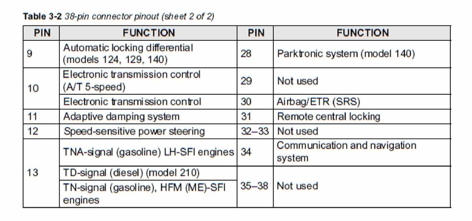
1 W140 Diagnostic Trouble Codes (DTC) Models with M119 Engine Only! The pages in this document have the Diagnostic Trouble Codes (DTC s) for the following models, all of which have M119 V8 engines with LH-SFI (LH Sequential Fuel Injection): SE, 400SEL, 400SEC (4.2L M engine) SE, 500SEL, 500SEC (5.0L M engine) S420, S500 (4.2L and 5.0L M119.97x engines) The chassis covered are: , (Sedan with 4.2L M engine) (Coupe with 4.2L M engine) , (Sedan with 5.0L M engine) (Coupe with 5.0L M engine) The diagnostic connector has a total of 38 pins; please see the next several pages which explain the specifics of each pin. Note that not all pins are used. Also, for models with the 4.2L engine, ASR traction control was optional. The DTC s are slightly different on pins 6 and 7, between models with ABS only (no ASR), and models with both ABS and ASR. Please make sure you are using the correct sheets when looking up codes for ABS/ASR, and the EA/CC/ISC systems! To determine if your vehicle has ASR, check the instrument cluster. Models with ASR will have an illuminated yellow warning triangle in the top/center of the speedometer. All USA models with 5.0L engines have ASR as standard equipment. Models without ASR have a CC/ISC (Cruise Control / Idle Speed Control) module, N4/3, which controls the CC/ISC actuator (M16/. The ABS control module is N30. Models with ASR have an EA/CC/ISC (Electronic Accelerator / Cruise Control / Idle Speed Control) module, N4/1, which controls the EA/CC/ISC actuator (M16/. The ABS/ASR control module is N30/1. Most systems have analog blink codes available, which can be read with the factory impulse counter tool, or a home-made LED light box. However, the digital 3- or 4-digit codes are often more specific than the analog 1- or 2-digit codes. Certain systems can only have their codes read with a Mercedes digital scanner, such as the HHT (Hand Held Tester) or SDS (Star Diagnosis System); or with an aftermarket digital scan tool (such as the Snap-On MT2500, Modis, or Solus). For example, the SRS / Airbag system (pin #30) as of 07/1993 production (i.e., as of model year 1994) requires a digital scanner to communicate, no blink codes are available for this system. One other system (ACC, Automatic Climate Control) does not have analog blink codes available at the 38- pin connector. The ACC codes can be accessed with a digital scanner, or with the ACC control panel inside the vehicle. Please see the ACC documentation for details on this procedure. The Check Engine Light (CEL) may only be present on models with California emissions. Only these models will have a Diagnostic Module (DM). DM codes can be read using the built-in pushbutton & LED mounted at the front corner of the CAN box, near the 38-pin connector. ONLY codes from the DM will show using the built-in LED: you cannot read codes from the LH, ABS, ASR, E-GAS, etc from this LED!! You can also read the DM blink codes with a digital scanner, or by using a separate LED impulse counter code reader at pin #19.
 140.063 (Coupe with 4.2L M119.971 engine) 140.050, 140.051 (Sedan with 5.0L M119.")
2 This document includes the complete list of DTC s for the following systems: Pin #4 LH-SFI (LH Sequential Fuel Injection) (WIS Group 07.41, subgroup 3.1, section #11, five pages) Pin #6 - ABS (Anti-lock Brake System) - For models without ASR (WIS Group 42.30, subgroup 6.2, section #11, one page) Pin #6 - ABS / ASR (Anti-lock Brake System / ASR) - For models with ASR traction control (WIS Group 42.40, subgroup 5.2, section #12, two pages) Pin #7 - CC/ISC (Cruise Control / Idle Speed Control) - For models without ASR (WIS Group 30.21, subgroup 6.2, section #11, two pages) aka E-GAS Module Pin #7 - EA/CC/ISC (Electronic Accelerator / CC / ISC) - For models with ASR traction control (WIS Group 30.20, subgroup 6.2, section #11, two pages) aka E-GAS Module Pin #8 - Base Module (Power supply for the other modules has 4 fuses on top) aka Basic Module (WIS Group 54.21, subgroup 1.1, section #11, one page) Pin #11 - ADS (Adaptive Damping System) (WIS Group 32.32, subgroup 3.2, section 12, one page) Pin #12 - SPS / PML (Speed Sensitive Power Steering) (WIS Group 46.50, subgroup 7.1, section 11, one page) Pin #16 - ACC (Automatic Climate Control) - Blink codes not available at 38-pin connector, see documentation (WIS Group 83.40, subgroup 3.2, section 14, four pages)
 Pin #7 - CC/ISC (Cruise Control / Idle Speed Control) - For models without ASR (WIS Group 30.21, subgroup 6.")
3 Pin #17 - EZL (Digital Ignition System) (WIS Group 07.41, subgroup 5.2, section #11, two pages) Pin #19 - Diagnostic Module (CA models only will also have LED + pushbutton in front of CAN box) (WIS Group 07.41, subgroup 8.2, section #11, one page) Pin #20 PSE (Pneumatics System Equipment) (WIS Group 80.00, subgroup 3.1, section #12, one page) Pin #21 Convenience System (WIS Group 80.45, subgroup 5.1, section #12, two pages) Pin #23 - ATA (Anti-Theft Alarm) (WIS Group 80.50, subgroup 13.2, section #12, one page) Pin #30 - Airbag / SRS (Supplemental Restraint System) up to 07/1993 ( model years) (WIS Group 91.60, subgroup 16.2, section 12, one page) Only blink codes are available Pin #30 - Airbag / SRS (Supplemental Restraint System) as of 07/1993 ( model years) (WIS Group 91.60, subgroup 16.3, section 12, three pages) Only digital codes available Pin #31 IRCL (Infrared Remote Central Locking) (WIS Group 80.30, subgroup 4.2, section #12, one page)
 Pin #23 - ATA (Anti-Theft Alarm) (WIS Group 80.50, subgroup 13.")
4

5
6 Preliminary work: Engine Test and Adjustment, Engines, Volume 1 On-Off Ratio Test If a malfunction is no longer present during a subsequent engine start or The on-off ratio tests the operation of the O2S (Lambda) control system and engine operation, the total value recorded by the malfunction counter is additionally, recognizes certain malfunctions present during the test. reduced by 1 every time the engine is switched off. This procedure repeats Malfunctions are distinguished between those that occur with the itself until the malfunction counter is cleared. Ignition: ON and those that occur with the Engine: at CTP (idle). The on-off ratio can be checked with the on-off ratio tester or with the engine Stored malfunctions (DTC`s) can be read with the impulse counter scan tool analyzer. For this purpose, the purge line to the engine must be disconnected at the data link connector (X11/4). (Also see DM, Engines, Volume 2, section at the purge control valve and closed with a plug. Check on-off ratio at closed 5.) throttle speed and at 2500 rpm. A readout of 50% or an oscillating needle indicates that all input signals and the O2S control system are OK. Readouts of 10% to 90% or 95% refer to a particular malfunction source (see The DTC memory readout must be performed with the engine OFF and the Malfunction Tables). In addition, after testing the on-off ratio, an impulse ignition switched ON. readout must be performed using the impulse counter scan tool. Malfunctions occurring in the following areas are stored immediately: Diagnostic Trouble Code (DTC) Readout with Impulse Counter Scan CMP sensor, Tool. Hot-wire MAF sensor, Malfunctions which occur while starting or with the engine running are Injectors. recorded by a malfunction counter. Malfunctions are assigned a specific value according to malfunction severity (e.g. hot wire MAF sensor 128, ECT sensor A malfunction of the following is stored after more than 2 trips: 3. The malfunction counter counts in stages up to a threshold value of 255. TN-signal (input). After reaching the threshold value of 128, intermittent malfunctions are stored into memory after switching off the ignition. Malfunctions which affect engine The memory remains active even if the vehicle's battery is disconnected. operation ( 128) are immediately stored into DTC memory by the malfunction counter after switching off the ignition. DTC's can be read with the impulse counter scan tool. Numbers ranging from After eliminating the mentioned malfunctions or after trial installation of a LH- 1 to 32 may appear on the display of the impulse counter scan tool. SFI control module from another vehicle, the LH-SFI control module's self- The number 1 indicates: No DTC recognized in system. adaptation feature must be reset to its mean value (see Resetting LH-SFI All further numbers refer to a particular malfunction source. If there are Control Module's Self-Adaptation Feature to Mean Value" 11/4 or with HHT multiple system malfunctions, the malfunction assigned with the lowest menu selection 5 Self-Adaptation). number will be displayed first. The LH-SFI control module will also adapt itself during the course of vehicle If the DTC number indicated first reappears after more than two DTC operation. readouts, then no further malfunctions are stored in the system's memory. After eliminating all malfunctions, they must be cleared individually and the ignition must be switched off for a minimum of 15 seconds. In case of engine running complaints, the DTC memory must be read and the malfunction must be eliminated before proceeding with any additional repairs. LH-SFI Control Module Self-Adaptation Feature A self-adaptation feature for the emission control system is incorporated into the LH-SFI control module. If malfunctions of the: Hot-wire MAF sensor, Injectors, Purge control valve, Diaphragm pressure regulator, Purge valve occur or if intake air leaks are present, the LH-SFI control module conducts a self-adaptation process whereby the correction factors are continuously calculated and permanently stored. Copyright Daimler AG 11/3/08 G/06/08. This WIS printout will not be recorded by the update service. Page 1
.")
7 Notes for HHT Fault search with HHT. Diagnostic trouble code (DTC) memory: Select Current DTC's". If the actual condition changes, e.g. when wiggling a connector, the change is reported optically and acoustically so that troubleshooting can be performed directly with the HHT. Loose connections. Loose connections are stored if they occur several times in a certain time period. Therefore, they can appear only as Stored DTC's" and never as Current DTC's". Nominal values. All nominal values relative to the actual values as shown on the HHT are listed in the DM, Engines, Volume 1, section A. Actual values for ECT, IAT and MAF. In case of an open or short circuit, the actual value is immediately replaced by a substitute value which is very close to the actual value. Therefore, a fault can not be recognized clearly. A readout of the fault is possible only via the diagnostic trouble code (DTC) memory. Actual value for engine rpm. In case of the engine rpm's, the HHT display shows the closed throttle (idle) speed nominal value calculated by the control module on the left, and on the right, the rpm actual value. Both values should differ from each other only slightly. The permissible tolerances are not known. Preparation for Test with Impulse Counter Scan Tool Clearing Diagnostic Trouble Code (DTC) Memory Connect impulse counter scan tool and on-off ratio tester according to a) Press start button for 2 to 4 seconds (DTC readout appears). connection diagram. b) Wait 3 seconds, press start button for 6 to 8 seconds, thereby clearing Reading Diagnostic Trouble Code (DTC) Memory the previously displayed DTC from memory. a) Ignition: ON c) Each stored DTC must be cleared individually. b) Press start button for 2 to 4 seconds. d) Ignition: OFF and wait 15 seconds. c) Read and record DTC readout. Check if all stored DTC's are eliminated. d) Press start button again for 2 to 4 seconds. e) Ignition: ON e) Read and record DTC readout. f) Repeat DTC readout. The number " (no DTC stored) must appear. Repeat steps d) and e) until the first DTC reappears. Resetting LH-SFI Control Module's Self-Adaptation Feature to Mean Value After the number " appears on the display, press start button for 6 to 8 seconds. Ignition: OFF and wait 30 seconds. Special Tools Copyright Daimler AG 11/3/08 G/06/08. This WIS printout will not be recorded by the update service. Page 2

8 Connection Diagram - Impulse Counter Scan Tool and On-Off Ratio Tester or Engine Analyzer with Diagnostic Socket X11 Note: Connect red wire of impulse counter scan tool to socket 3, black wire of impulse counter scan tool to socket 1, yellow wire of impulse counter scan tool as follows: LH-SFI control module Socket 4 DI control module Socket 17 Base module Socket 8 EA/CC/ISC control module Socket 7 Diagnostic module Socket 19 Figure On-off ratio tester 013 Impulse counter scan tool 075 Impulse counter scan tool adaptor X11 Diagnostic socket (9-pole) X11/4 Data link connector (DTC readout) U Connection Diagram - Impulse Counter Scan Tool/ Hand-Held Tester and On-Off Ratio Tester without Diagnostic Socket X11 Note: Connect red wire of impulse counter scan tool to socket 3, black wire of impulse counter scan tool to socket 1, yellow wire of impulse counter scan tool as follows: LH-SFI control module Socket 4 Base module Socket 8 EA/CC/ISC control module Socket 7 Diagnostic module Socket 19 RPM signal (TN output) Socket 13 On-off ratio readout Socket 14 Circuit 31 Socket 1 Circuit 30 Socket 3 Figure On-off ratio tester 013 Impulse counter scan tool 034 Test cable Red alligator clip to socket 3 Black alligator clip to socket 1 Black male plug to socket 14 Green male plug not connected Yellow male plug not connected 075 Impulse counter scan tool adaptor U Hand-Held Tester (optional with impulse counter scan tool 094 Multiplex cable X11/4 Data link connector (DTC readout) a) On-Off Ratio Test, Ignition: ON On-Off Ratio % Possible cause Test step/remedy Voltage supply from socket 3 of data link connector (X11/4) open circuit Repair harness CTP (idle) recognition inactive WOT (full load) recognition active o o Engine coolant temperature < 70 C or >110 C , 10.0 Not used Input signals OK TN-signal (rpm signal) or CMP sensor signal not present while starting Starter engaged CAN-data exchange defective Copyright Daimler AG 11/3/08 G/06/08. This WIS printout will not be recorded by the update service. Page 3
 U07-5004-57 Connection Diagram - Impulse Counter Scan Tool/ Hand-Held Tester and On-Off Ratio Tester without Diagnostic Socket X11 Note: Connect red wire of impulse counter scan tool to")
9 Fuel safety shut-off active Check CC/ISC (see DM, Engines, Volume 3, Section 7. or Check EA (see DM, Engines, Volume 3, Section 6. b) On-Off Ratio Test, Engine: at CTP (idle) On-Off Ratio % Possible cause Test step/remedy Short circuit to battery + in wire to data link connector (X11/4), socket 3 CTP (idle) recognition applied constantly Output of fuel injectors or one or more fuel injectors have open circuit ECT sensor (B11/ Hot wire MAF sensor (B2/ O2S 1 (before TWC) (G3/ not operational or defective, open circuit CMP sensor (L5/ TN-signal (rpm signal) CAN-data exchange defective Needle oscillates if all monitored signals are OK. Repair harness , , , , Either EA/CC/ISC control module, CC/ ISC control module or DI control module not transmitting. b) On-Off Ratio Test, Engine: at CTP (idle) On-off Ratio % Possible cause Test step/remedy Vehicle speed signal (VSS) Deceleration shut-off active No voltage at LH-SFI control module (N3/ Check CC/ISC (see DM, Engines, Volume 3, section 7. or Check EA (see DM, Engines, Volume 3, section 6. Check CC/ISC (see DM, Engines, Volume 3, section 7. or Check EA (see DM, Engines, Volume 3, section c) LH-SFI Control Module DTC Readout DTC Possible cause Test step/remedy 4) No malfunction in system - ECT sensor (B11/ sensor circuit 1, open/short circuit ECT sensor (B11/ sensor circuit 2, open/short circuit Voltage at hot wire MAF sensor (B2/ insufficient or too high, or open circuit in ground wire at hot wire MAF sensor Not used - Not used - TN-signal (rpm signal) incorrect or open/short circuit CMP sensor (L5/ signal, open/short circuit Starter signal (circuit 50) missing, open/short circuit CTP (idle) recognition from EA/CC/ISC control module (N4/ or CC/ISC control module (N4/, short circuit Secondary air injection system, open/short circuit DTC can be displayed on vehicles up to 7/91 even if no fault is present. DTC can be displayed on vehicles up to 7/91 even if no fault is present. 4) DTC can be displayed on vehicles up to 7/91 even if no fault is present. c) LH-SFI Control Module DTC Readout DTC Possible cause Test step/remedy Copyright Daimler AG 11/3/08 G/06/08. This WIS printout will not be recorded by the update service. Page 4
 CAN-data exchange defective Needle oscillates if all monitored signals are OK. Repair harness 23 15.0 23 32.0, 33.0 23 9.0, 10.1 23 5.0, 6.0 23 18.0-19.1 23 14.")
10 5) 7) 6) Burn-off control for hot wire MAF sensor, open/short circuit IAT sensor (B17/7), open/short circuit Not used Not used - EGR switchover valve (Y27), open/short circuit No CAN data transmission with EA/CC/ISC control module (N4/ or CC/ISC control module (N4/ or N4/1 or N4/3. No CAN data transmission with DI control module (N1/ or N1/3. Not used - No CAN data transmission from LH-SFI control module (N3/ O2S 1 (before TWC) (G3/, open/short circuit ) DTC can be displayed on vehicles up to 7/91 even if no fault is present. 6) DTC can be displayed on vehicles up to 7/91 even if no fault is present. 7) DTC can be displayed even if no fault is present. c) LH-SFI Control Module DTC Readout DTC Possible cause Test step/remedy (Engine 119 only) (Model only) O2S 1 heater, open/short circuit Purge control valve (Y58/, open/short circuit Left adjustable camshaft timing solenoid (Y49/, open/short circuit Adjustable camshaft timing solenoid, engine 104 (Y49) or right adjustable timing solenoid, engine 119 (Y49/, open/short circuit Upshift delay switchover valve (Y3/, open/short circuit Injectors (Y6, open/short circuit LH-SFI control module coding, open circuit 1GR start relay module (K29/, open/short circuit Copyright Daimler AG 11/3/08 G/06/08. This WIS printout will not be recorded by the update service. Page 5
 DTC can be displayed on vehicles up to 7/91 even if no fault is present. 6) DTC can be displayed on vehicles up to 7/91 even if no fault is present.")
11 Test Preparation for DTC Readout 2. Ignition: ON. 1. Connect impulse counter scan tool or Hand-Held Tester to data link 3. Read DTC memory of ABS control module (N30), and base module connector (X11/4) as shown in section 0. (N16/. Note: Connect yellow wire from impulse counter scan tool as follows: ABS control module (N30) socket 6 Base module (N16/ socket 8 Special Tools Equipment Hand-Held Tester (HHT) see applicable Service Information in groups 58 and 99 No faults recognized. In case of complaint: Left front axle vehicle speed sensor (L6/, open circuit Right front axle vehicle speed sensor (L6/, open circuit Rear axle vehicle speed sensor (L6), open circuit Left front axle solenoid valve (A7y Right front axle solenoid valve (A7y Rear axle solenoid valve (A7y Return pump (A7m or return pump relay (A7k Solenoid valve relay (A7k Models /05: Master cylinder switchover valve (Y6 Brake lamp switch (S9/ Models /05: Lateral acceleration sensor (B24/ ABS control module (N30) 23 (entire test) N30 Vehicle speed sensors (L6, L6/1, L6/, implausible signal Solenoid valve relay (A7k Left front axle vehicle speed sensor (L6/, implausible signal Right front axle vehicle speed sensor (L6/, implausible signal Rear axle vehicle speed sensor (L6), implausible signal Models /05: Lateral acceleration sensor (B24/, implausible signal Visual inspection Incorrect number of rotor teeth, dirty or damaged, incorrect rear axle ratio, tires or wheels. Copyright Daimler AG 11/3/08 G/06/08. This WIS printout will not be recorded by the update service. Page 1

12 Preparation for DTC Readout 1. Connect impulse counter scan tool or Hand-Held Tester (HHT) to data link connector (X11/4) according to connection diagram (see section 0). Note: Connect yellow wire from impulse counter scan tool to: ABS/ASR control module (N30/ socket 6 BM (N16/ socket 8 SPS control module (N49/ socket 12 ADS control module (N5 socket 11 TCM (N15/ socket 10 EA/CC/ISC control module (N4/ socket 7 Engine (N3/4), LH-SFI (N3/ or Right LH-SFI control module (N3/ socket 4 Left LH-SFI control module (N3/ socket 5 DI (N1/ or Right DI control module (N1/5) socket 17 Left DI control module (N1/4) socket Ignition: ON 3. Read out DTC`s for control modules listed. Special Tools Equipment Hand-Held Tester (HHT) See S.I. in groups 58 and 99. Models (02/92 ), , /05/07 No fault in system. Left front axle VSS sensor (L6/, open circuit Right front axle VSS sensor (L6/, open circuit Left rear axle VSS sensor (L6/, open circuit Right rear axle VSS sensor (L6/4), open circuit ABS/ASR hydraulic unit, left front axle solenoid valve (A7/3y ABS/ASR hydraulic unit, right front axle solenoid valve (A7/3y ABS/ASR hydraulic unit, left rear axle solenoid valve (A7/3y ABS/ASR hydraulic unit, right rear axle solenoid valve (A7/3y4) ABS/ASR hydraulic unit, high-pressure/return pump relay (A7/3k, ABS/ASR hydraulic unit, high-pressure/return pump (A7/3m ABS/ASR hydraulic unit, solenoid valve relay (A7/3k Master brake cylinder switchover valve (Y6 Stop lamp switch (S9/ In case of complaint: 23 and 33 (entire test) Model (02/93 ), , /04/07 ABS lateral acceleration sensor (B24/, open circuit ABS/ASR control module (N30/ Replace N30/1 Vehicle speed signal (VSS) (L6/1, L6/2, L6/3, L6/4), implausible 2 3 ) ) Visually inspect Battery voltage too low ABS/ASR hydraulic unit, switchover/solenoid valve (A7/3y5) ABS/ASR hydraulic unit, pressure switch (A7/3s, charge , ABS/ASR hydraulic unit, pressure switch (A7/3s, leakage , ABS/ASR hydraulic unit, pressure switch (A7/3s, hydraulic , ) Rotor with incorrect tooth count, dirt accumulation on or damaged rotor, incorrect rear axle ratio, wrong wheel or tire size. 3 ) If DTC appears only after repair work, it was caused by applying the brakes or driving vehicle on a dynamometer, erase DTC. Copyright Daimler AG 11/3/08 G/06/08. This WIS printout will not be recorded by the update service. Page 1
 socket 17 Left DI control module (N1/4) socket 18 2. Ignition: ON 3. Read out DTC`s for control modules listed. Special Tools Equipment Hand-Held Tester (HHT) See S.I. in groups 58 and 99.")
13 Model (02/93 ), , /04/07 ASR charging pump (M15) 2 Left front axle VSS sensor (L6/, implausible ) 2 Right front axle VSS sensor (L6/, implausible ) 2 Left rear axle VSS sensor (L6/, implausible ) 2 Right rear axle VSS sensor (L6/4), implausible ) ABS lateral acceleration sensor (B24/, implausible CAN data bus to EA/CC/ISC control module (N4/, interrupted 1 ) 2 ) Rotor with incorrect tooth count, dirt accumulation on or damaged rotor, incorrect rear axle ratio, wrong wheel or tire size. Wiring, , Visually inspect Visually inspect Visually inspect Visually inspect Read out DTC for N4/1: see DM, Engines, Vol. 2, sections 6.2 or CAN data bus to LH-SFI control module (N3/, Left LH-SFI control module (N3/, Right LH-SFI control module (N3/, or Engine control module (N 3/4), interrupted CAN data bus to DI control module (N1/, Left DI control module (N1/4), Right DI control module (N1/5), interrupted CAN data bus, interrupted Read out DTC for N3/1, N3/2, N3/3, N3/4: see DM, Engines, Vol. 2, sections 1.1, 3.1 or Read out DTC for N1/3, N1/4, N1/5: see DM, Engines, Vol. 2 sections 5.2 or Read out DTC for N4/1: see DM, Engines, Vol. 2, sections 6.2 or Read out DTC for N1/3, N1/4, N1/5: see DM, Engines, Vol. 2 sections 5.2 or Read out DTC for N3/1, N3/2, N3/3, N3/4: see DM, Engines, Vol. 2, sections 1.1, 3.1 or Read out DTC for N15/1: see DM, Chassis & Drivetrain, Vol. 1 section Copyright Daimler AG 11/3/08 G/06/08. This WIS printout will not be recorded by the update service. Page 2

14 Diagnosis - Diagnostic Trouble Code (DTC) Readout Preparation for DTC Readout Connect impulse counter scan tool and/or HHT to data link connector (X11/4) according to connection diagram (see section 0). yellow wire to socket 7 Special Tools Equipment Hand-Held Tester (HHT) see current MBNA service information in groups 58 and 99 Available through the MBNA Standard Equipment Program. Diagnosis - Diagnostic Trouble Code (DTC) Readout No fault in system - CC/ISC control module (N4/ N4/3 Safety contact switch (M16/3s Stop lamp switch (S9/ Cruise control switch (S40) OFF CC/ISC control module (N4/ N4/3 Actual value potentiometer (M16/1r , 5.0 Starter lock-out/back-up lamp switch (S16/ (transmission range recognition) Engine speed (TNA) signal Vehicle speed signal (VSS) , 16.0 Safety relay within CC/ISC control module (N4/ N4/3 CC/ISC control module (N4/ N4/3 Engine harness Check harness wire insulation. Conditions for activation of CC/ISC actuator (M16/ not fulfilled. Conditions: Engine: OFF Transmission range: P/N Diagnosis - Diagnostic Trouble Code (DTC) Readout CC/ISC actuator (M16/ Throttle valve actual valve potentiometer (M16/2r Drive actual value potentiometer (M16/2r Safety contact switch (M16/2s Closed throttle recognition switch (M16/2s CC/ISC actuator (M16/ (voltage supply) Reset not accomplished (actuator adaptation) Cruise control switch (S40) Stop lamp switch (S9/ Not valid for U.S.A. vehicles , , Erase DTC: Ignition: OFF Ignition: ON (for at least 90 seconds). If DTC reappears: CC/ISC actuator (M16/ Diagnosis - Diagnostic Trouble Code (DTC) Readout CAN databus: N4/3 Message from CC/ISC control module (N4/ faulty Reception from LH-SFI control module (N3/ faulty Left front axle vehicle speed signal (L6/ from ABS control module (N30) Rear axle vehicle speed signal (L6) from ABS control module (N30) Engine speed signal (TNA) from base module (N16/ Fuel safety shut-off signal to LH-SFI control module (N3/ Closed throttle recognition signal to LH-SFI control module (N3/ Copyright Daimler AG 11/3/08 G/06/08. This WIS printout will not be recorded by the update service. Page 1
 OFF 23 2.0 CC/ISC control module (N4/ N4/3 Actual value potentiometer (M16/1r 23 3.0, 5.")
15 Voltage supply, circuit Copyright Daimler AG 11/3/08 G/06/08. This WIS printout will not be recorded by the update service. Page 2

16 Diagnosis - Diagnostic Trouble Code (DTC) Readout Preparation for DTC Readout Connect impulse counter scan tool and/or HHT to data link connector (X11/4) according to connection diagram. Yellow wire to socket 7 Note The Test Program is divided into two sections: Electronic accelerator with ISC Cruise control According to the diagnosis made, troubleshoot by performing only the related test steps in the particular group. Special Tools Equipment Hand-Held Tester (HHT) see current MBNA service information in groups 58 and 99 Diagnosis - Diagnostic Trouble Code (DTC) Readout Observe Preparation for Test. No fault in system - EA/CC/ISC control module (N4/ N4/1 Safety contact switch (M16/1s , 6.0 Stop lamp switch (S9/ , 3.0 Safety contact switch (M16/1s , 7.0 Criuse control switch (S40) OFF EA/CC/ISC control module (N4/ N4/1 Actual value potentiometer (M16/1r , 4.0 Starter lock-out/back-up lamp switch (S16/ (transmission range recognition) Closed throttle position switch (S29/ Engine speed (TNA) signal Vehicle speed signal (VSS) Safety relay within EA/CC/ISC control module (N4/ N4/1 EA/CC/ISC control module (N4/ N4/1 Engine harness Check harness wire insulation. Conditions for activation of EA/CC/ISC actuator (M16/ not fulfilled. Conditions: Engine: OFF Transmission range: P/N Diagnosis - Diagnostic Trouble Code (DTC) Readout Diagnostic trouble code (DTC) Possible caus Test step/remedy EA/CC/ISC actuator (M16/ Reference potentiometer (M16/1r Actual value potentiometer (M16/1r Safety contact switch (M16/1s Closed throttle position switch (M16/1s , , , , 6.0 Actuator motor (M16/1m Magnetic clutch (M16/1k Reset not accomplished (actuator adaptation) Cruise control switch (S40) Erase DTCs: Ignition: OFF Ignition: ON (for at least 90 seconds). If DTC appears: EA/CC/ISC actuator (M16/ Stop lamp switch (S9/ Starter lock-out/backup lamp switch (S16/ , Not valid for U.S.A. vehicles Observe Preparation for Test. CAN databus: Message from EA/CC/ISC control module (N4/ faulty Message from ABS/ASR control module (N30/ faulty Message from LH-SFI control module (N3/ faulty N4/1, Diagnosis - Diagnostic Trouble Code (DTC) Readout Copyright Daimler AG 11/3/08 G/06/08. This WIS printout will not be recorded by the update service. Page 1
 see current MBNA service information in groups 58 and 99 Diagnosis - Diagnostic Trouble Code (DTC) Readout Observe")
17 Observe Preparation for Test. Left front axle vehicle speed signal (L6/ from ABS/ASR control module (N30/ Left rear axle vehicle speed signal (L6/ from ABS/ASR control module (N30/ Engine speed signal (TNA) from base module (N16/ Fuel safety shut-off signal to LH-SFI control module (N3/ Closed throttle recognition signal to LH-SFI control module (N3/ Voltage supply, circuit 87 Closed throttle position switch (S29/ Data exchange with ABS/ASR control module (N30/ implausible N30/ Copyright Daimler AG 11/3/08 G/06/08. This WIS printout will not be recorded by the update service. Page 2

18 CAUTION! On vehicles with ME-SFI (for identication see: control module box), the base module (BM) (N16/ is not equipped with DTC memory. DTC`s can only be retrieved by performing the Electrical Test Program 23. Test Preparation for DTC Readout 1. Connect impulse counter scan tool and adapter or HHT to data link connector (X11/4) as shown in section 0. Note: Connect yellow wire from impulse counter scan tool as follows: Base module (BM) (N16/ socket 8 ABS or ASR control module (N30 or N30/ or ASR/SPS control module (N47- or ESP/SPS control module (N47-5) socket 6 SPS control module (N49/ socket 12 ADS control module (N5 socket 11 EDS control module (N39), LH-SFI or Right LH-SFI control module (N3/1 or N3/,ME-SFI (Engine 119) or ME-SFI (Engine 120) right engine control module (N3/10, N3/1 socket 4 Left LH-SFI control module (N3/ or ME-SFI (Engine 120) left engine control module (N3/1 socket 5 2. Ignition: ON 3. Read DTC memory (as applicable) for appropriately connected: BM, ABS or ASR, ASR/SPS, ESP/SPS, ME-SFI, ADS, LH-SFI control modules. Special Tools Equipment Description Hand-Held Tester (HHT) see applicable Service Information in groups 58 and 99 Available through the MBNA Standard Equipment Program. DTC Possible cause Test step/remedy No fault in system. 2 Maximum allowable temperature in module box (F2 exceeded ). A/C electromagnetic clutch (A9k jammed or poly-v-belt broken. Poly-V-belt slips. Engine 120: Left LH-SFI control module (N3/ voltage supply, open circuit. Engine 104, 119: LH-SFI control module (N3/ voltage supply, open circuit. Engine 120: Right LH-SFI control module (N3/ voltage supply, open circuit. Base module (N16/ voltage supply output fuse F2, open circuit. Base module (N16/ voltage supply output fuse F3, open circuit. Base module (N16/ voltage supply output fuse F1, open circuit. Base module (N16/ voltage supply output fuse F4, open circuit. Kickdown switch (transmission mode) (S16/7), short circuit. A/C electromagnetic clutch (A9k, short circuit. 2 Module box blower motor (M2/, short circuit ). In case of complaint: (entire test) , visually inspect compressor and poly-v-belt , check poly-v-belt tension , , Module box blower motor was phased out of production on model 140 starting M.Y Copyright Daimler AG 11/3/08 G/06/08. This WIS printout will not be recorded by the update service. Page 1
 (N16/ socket 8 ABS or ASR control module (N30 or N30/ or ASR/SPS control module (N47- or ESP/SPS control module")
19 Test Preparation for DTC Readout 1. Connect impulse counter scan tool or Hand-Held Tester (HHT) to the data link connector (X11/4) according to the connection diagram as shown in section 0. Note: Connect yellow wire from impulse counter scan tool to: ADS control module (N5 socket 11 Base module (N16/ socket 8 2. Read out any stored DTC`s from ADS control module (N5 and BM (N16/. Special Tools No fault in system. ADS control module (N5 Replace N51. Body acceleration sensor (B24) Wheel acceleration sensor (B24/ Steering angle sensor (N49) Left/right front axle solenoid valve 1 (Y51y1, Y52y Left/right front axle solenoid valve 2 (Y51y2, Y52y Left/right rear axle solenoid valve 1 (Y53y1, Y54y Left/right rear axle solenoid valve 2 (Y53y2, Y54y Not for U.S.A. vehicles. Not for U.S.A. vehicles. Model 129 Left front (VSS) from ABS or ABS/ASR control module Model 140 Right front (VSS) from ABS or ABS/ASR control module In case of complaint: 23 and 33 (entire test) , , Model 129 only Oil level switch (S44) Steering angle sensor (N49) not initialized Comfort/sport switch (S45/, short circuit Not for U.S.A. vehicles. Vehicle load sensor (N51/ ADS MIL (A1e27) Voltage supply too low Steering angle sensor (N49) Voltage supply too high Comfort/sport switch (S45/ Not for U.S.A. vehicles Copyright Daimler AG 11/3/08 G/06/08. This WIS printout will not be recorded by the update service. Page 1
 Wheel acceleration sensor (B24/ Steering angle sensor (N49) Left/right front axle solenoid valve 1 (Y51y1, Y52y Left/right front axle solenoid valve 2 (Y51y2, Y52y")
20 Test Preparation for DTC Readout 2. Ignition: ON. 1. Connect impulse counter scan tool or Hand-Held Tester to data link 3. Read DTC memory of SPS control module (N49/, and base connector (X11/4) as shown in section 0. module (N16/. Note: Connect yellow wire from impulse counter scan tool as follows: SPS control module (N49/ socket 12 Base module (N16/ socket 8 Special Tools Equipment Hand-Held Tester (HHT) see applicable Service Information in groups 58 and 99 Model (LH-SFI up 05/9, (diesel) No fault recognized. In case of complaint: 23 (entire test) Speed-sensitive power steering control module (N49/ N49/1 Rear axle/left rear axle vehicle speed signal malfunction Right rear axle vehicle speed signal malfunction Comparison of left and right rear axle vehicle speed signals malfunctioning Vehicle speed signal from axle missing Vehicle speed signal from transmission missing Short circuit between speed sensitive power steering P-valve (Y10) (+) and U BATT Speed-sensitive power steering P-valve (Y10), short circuit Speed-sensitive power steering P-valve (Y10), open circuit Voltage supply to speed-sensitive power steering control module (N49/ insufficient voltage Model (HFM-SFI and LH-SFI as of 06/9 No fault recognized. In case of complaint: Speed-sensitive power steering control module (N49/ N49/1 Comparison of axle vehicle speed signal status/left front axle vehicle speed signal malfunctioning Axle vehicle speed signal status missing Speed-sensitive power steering control module (N49/ N49/1 Speed sensitive power steering P-valve (Y10); short circuit Speed sensitive power steering P-valve (Y10); open circuit Short circuit between speed sensitive power steering P-valve (Y10) (+) and U BATT 23 (entire test) Copyright Daimler AG 11/3/08 G/06/08. This WIS printout will not be recorded by the update service. Page 1
 No fault recognized.")
21 Notes for Diagnosis The A/C pushbutton control module (N2 has DTC memory and the capability to display the codes via the temperature display windows (arrows) on the A/C pushbutton control panel. The stored DTC's will remain in memory even with the vehicle battery disconnected. The DTC memory can also be read using the Hand-Held Tester (HHT). The DTC readout differentiates between continuous as well as intermittent faults. Figure 1 P B Preparation for Test 8. Turn ignition OFF and repair recorded DTC's according to the 1. Turn left temperature selector wheel to red" detent. respective diagnostic chart. 2. Turn right temperature selector wheel to blue" detent. 9. Turn ignition ON and press left button. A d" (delete) is displayed in the left window. 3. Turn ignition ON. 4. Press. By pressing the right memory. Continue to press the left and right button the DTC will be deleted from buttons until all DTC's 5. Within 20 seconds simultaneously press and for > 2 are deleted from memory (display will show ). seconds. 10. Return temperature selector wheels to normal setting. 6. The display will show permanent DTC's stored in memory (see Note: table on following page). Press right until all stored DTC's are The red diode in the recirculation switch will blink during the test as of displayed. Record each DTC as it is displayed. software status 6.2 (Bosch) or 06 (Kammerer). 7. Each malfunction (short circuit, open circuit, etc.) has a specific DTC. The letter (Error) along with the hundredth digit of the DTC is displayed in the left window. The tenth and single digit of the DTC is displayed in the right window. By pressing the right button the next DTC stored in memory will be displayed. Left display Right display hundredth digit single digit tenth digit Diagnostic Trouble Possible Cause Test Step/Remedy Code (DTC) No malfunction stored in memory - A/C pushbutton control module (N2 Rear A/C pushbutton control module (N22/ Connection to switchover valve block (Y1 Data exchange (CAN B), short circuit Data exchange (CAN A), short circuit Data exchange (CAN A and B), short circuit Repeat DTC readout - Data exchange (CAN B), open circuit Data exchange (CAN A), open circuit Connection to rear A/C pushbutton control module Data exchange (CAN B), open circuit (rear A/C control module) Data exchange (CAN A), open circuit (rear A/C control module) A/C pushbutton control module (N2. Rear A/C pushbutton control module (N22/. Diagnostic Trouble Possible Cause Test Step/Remedy Code (DTC) In-car temperature sensor (B10/4), short circuit Copyright Daimler AG 11/3/08 G/06/08. This WIS printout will not be recorded by the update service. Page 1 Wiring. Wiring. Wiring. Wiring. Wiring. Wiring. Wiring. Wiring. Wiring.
22 In-car temperature sensor (B10/4), short circuit In-car temperature sensor (B10/4), open or short circuit In-car temperature sensor (B10/4), open or short circuit Left heater core temperature sensor (B10/, short circuit Left heater core temperature sensor (B10/, short circuit Left heater core temperature sensor (B10/, open or short circuit Left heater core temperature sensor (B10/, open or short circuit Right heater core temperature sensor (B10/, short circuit Right heater core temperature sensor (B10/, short circuit Right heater core temperature sensor (B10/, open or short circuit Right heater core temperature sensor (B10/, open or short circuit Outside temperature sensor (B10/5), short circuit Outside temperature sensor (B10/5), short circuit Continuous faults. Intermittent faults. Diagnostic Trouble Possible Cause Test Step/Remedy Code (DTC) Outside temperature sensor (B10/5), open or short circuit Outside temperature sensor (B10/5), open or short circuit Evaporator temperature sensor (B10/6), short circuit Evaporator temperature sensor (B10/6), short circuit Evaporator temperature sensor (B10/6), open or short circuit Evaporator temperature sensor (B10/6), open or short circuit ECT sensor (B10/8), short circuit ECT sensor (B10/8), short circuit ECT sensor (B10/8), open or short circuit ECT sensor (B10/8), open or short circuit Refrigerant pressure sensor (B1, short circuit Refrigerant pressure sensor (B1, short circuit Refrigerant pressure sensor (B1, open or short circuit Refrigerant pressure sensor (B1, open or short circuit Continuous faults. Intermittent faults. Diagnostic Trouble Possible Cause Test Step/Remedy Code (DTC) Left temperature selector wheel, short circuit Left temperature selector wheel, short circuit Left temperature selector wheel, open or short circuit Left temperature selector wheel, open or short circuit Right temperature selector wheel, short circuit Right temperature selector wheel, short circuit Right temperature selector wheel, open or short circuit Right temperature selector wheel, open or short circuit Heater supply unit coolant circulation pump (A31m, short circuit Heater supply unit coolant circulation pump (A31m, short circuit Coolant circulation pump (A31m, open or short circuit Coolant circulation pump (A31m, open or short circuit Coolant circulation pump (A31m, over load Check mechanical function of circulation pump Coolant circulation pump (A31m, over load Check mechanical function of circulation pump Continuous faults. Intermittent faults. Diagnostic Trouble Possible Cause Test Step/Remedy Code (DTC) Left duovalve (A31y, short circuit Left duovalve (A31y, short circuit Left duovalve (A31y, open or short circuit Left duovalve (A31y, open or short circuit Right duovalve (A31y, short circuit Right duovalve (A31y, short circuit Copyright Daimler AG 11/3/08 G/06/08. This WIS printout will not be recorded by the update service. Page 2
23 g ( y ), Right duovalve (A31y, open or short circuit Right duovalve (A31y, open or short circuit A/C compressor ground activation , 30.0 A/C compressor ground activation , 30.0 A/C compressor ground activation, open or short circuit , 30.0 A/C compressor ground activation, open or short circuit , 30.0 Auxiliary fan, 1st stage activation, short circuit Auxiliary fan, 1st stage activation, short circuit Auxiliary fan, 1st stage activation, open or short circuit Auxiliary fan, 1st stage activation, open or short circuit Continuous faults. Intermittent faults. Diagnostic Trouble Possible Cause Test Step/Remedy Code (DTC) Auxiliary fan, 2nd stage activation, short circuit Auxiliary fan, 2nd stage activation, short circuit Auxiliary fan, 2nd stage activation, open or short circuit Auxiliary fan, 2nd stage activation, open or short circuit Auxiliary fan, 3rd stage activation, short circuit Auxiliary fan, 3rd stage activation, short circuit Auxiliary fan, 3rd stage activation, open or short circuit Auxiliary fan, 3rd stage activation, open or short circuit Auxiliary coolant pump control relay module (K30), power supply, short circuit 4) Auxiliary coolant pump control relay module (K30), power supply, short circuit 4) Auxiliary coolant pump control relay module (K30), power supply, open or short circuit 4) Auxiliary coolant pump control relay module (K30), power supply, open or short circuit 4) Engine rpm increase diode matrix (V, short circuit Engine rpm increase diode matrix (V, short circuit Engine rpm increase diode matrix (V, open or short circuit Engine rpm increase diode matrix (V, open or short circuit Continuous faults. Intermittent faults. 4) Possible sequential failures 75, 83, 87, 99, I 03. Diagnostic Trouble Possible Cause Test Step/Remedy Code (DTC) Activated charcoal filter actuator (A32m (OPEN), short circuit , 18.0 Activated charcoal filter actuator (A32m (OPEN), short circuit , 18.0 Activated charcoal filter actuator (A32m (OPEN), open or short circuit , 18.0 Activated charcoal filter actuator (A32m (OPEN), open or short circuit , 18.0 Activated charcoal filter actuator (A32m (CLOSED), short circuit , 18.0 Activated charcoal filter actuator (A32m (CLOSED), short circuit , 18.0 Activated charcoal filter actuator (A32m (CLOSED), open or short circuit , 18.0 Activated charcoal filter actuator (A32m (CLOSED), open or short circuit , 18.0 Continuous faults. Intermittent faults. (Rear A/C) Note: The following DTC's appear only if vehicle is equipped with rear A/C system Diagnostic Trouble Possible Cause Test Step/Remedy Code (DTC) Left rear heater core temperature sensor (B10/9), short circuit Left rear heater core temperature sensor (B10/9), short circuit Left rear heater core temperature sensor (B10/9), open or short circuit Left rear heater core temperature sensor (B10/9), open or short circuit Right rear heater core temperature sensor (B10/10), short circuit Right rear heater core temperature sensor (B10/10), short circuit Right rear heater core temperature sensor (B10/10), open or short circuit Right rear heater core temperature sensor (B10/10), open or short circuit Left temperature selector wheel, short circuit Left temperature selector wheel, short circuit Left temperature selector wheel, open or short circuit Left temperature selector wheel, open or short circuit Copyright Daimler AG 11/3/08 G/06/08. This WIS printout will not be recorded by the update service. Page 3
24 Continuous faults. Intermittent faults. (Rear A/C) Diagnostic Trouble Possible Cause Test Step/Remedy Code (DTC) Right temperature selector wheel, short circuit Right temperature selector wheel, short circuit Right temperature selector wheel, open or short circuit Right temperature selector wheel, open or short circuit Rear evaporator temperature sensor (B10/1, short circuit Rear evaporator temperature sensor (B10/1, short circuit Rear evaporator temperature sensor (B10/1, open or short circuit Rear evaporator temperature sensor (B10/1, open or short circuit Coolant circulation pump (A31/1m, short circuit Coolant circulation pump (A31/1m, short circuit Coolant circulation pump (A31/1m, open or short circuit Coolant circulation pump (A31/1m, open or short circuit Coolant circulation pump (A31/1m, overload Coolant circulation pump (A31/1m, overload Continuous faults. Intermittent faults. (Rear A/C) Diagnostic Trouble Possible Cause Test Step/Remedy Code (DTC) Left duovalve (A31/1y, short circuit Left duovalve (A31/1y, short circuit Left duovalve (A31/1y, open or short circuit Left duovalve (A31/1y, open or short circuit Right duovalve (A31/1y, short circuit Right duovalve (A31/1y, short circuit Right duovalve (A31/1y, open or short circuit Right duovalve (A31/1y, open or short circuit Rear refrigerant shut-off valve (Y67), short circuit Rear refrigerant shut-off valve (Y67), short circuit Rear refrigerant shut-off valve (Y67), open or short circuit Rear refrigerant shut-off valve (Y67), open or short circuit Rear tunnel flap vacuum valve (Y67/, short circuit Rear tunnel flap vacuum valve (Y67/, short circuit Rear tunnel flap vacuum valve (Y67/, open or short circuit Rear tunnel flap vacuum valve (Y67/, open or short circuit Continuous faults. Intermittent faults. Copyright Daimler AG 11/3/08 G/06/08. This WIS printout will not be recorded by the update service. Page 4
25 Diagnostic Trouble Code (DTC) Readout with Impulse Counter Scan Tool. The DI control module (N1/ is equipped with DTC readout including Malfunctions can be recalled from memory using the impulse counter scan malfunction memory. tool with the engine off and the ignition ON". Numbers ranging from to Malfunctions which occur with the engine running are counted by a may appear on the display of the impulse counter scan tool. malfunction counter. A malfunction is recorded into memory only if the same The number indicates: No malfunction recognized in system. malfunction has occurred after 8 sequential engine starts. All further numbers refer to a particular malfunction source. If there are This prevents a malfunction from being recorded if, for example, it occurred multiple system malfunctions, the malfunction assigned with the lowest only once. If, for example, a malfunction occurred only 7 times, then the number will be displayed first. malfunction counter will be cleared again after a certain number of engine If the DTC readout number indicated first reappears after more than two DTC starts. readouts, then no further malfunctions are present in the system. The memory remains active even if the vehicle's battery is disconnected. Malfunctions occurring in the following areas are stored immediately: CKP sensor defective (diagnostic trouble code ). Magnets for CKP sensor not recognized (diagnostic trouble code ) (Engine 119 only). After eliminating all malfunctions, the DTC's must be cleared individually In.case of engine complaints, the DTC memory must be read and the malfunction must be eliminated before proceeding with any additional repairs. Preparation for Test with Impulse Counter Scan Tool Connect impulse counter scan tool according to connection diagram (see section 0). Read DTC memory (see section 0). Special Tools DTC Possible cause Test step/remedy No malfunction in system - Maximum retard setting on at least one cylinder has been reached Increased knock tendency, i.e. due to poor fuel quality, carbon build-up, mechanical damage. Not used - MAP sensor in DI control module (N1/ defective Check vacuum supply to N1/3, Replace N1/3. Knock sensor 1 and/or 2 defective Knock sensor not plugged in at N1/3, Replace knock sensor. CMP sensor (L5/ defective Knock control-output switch in DI control module (N1/ defective Replace N1/3. Transmission overload protection switch (S65) does not close Transmission overload protection switch (S65) does not open Not used - Reference resistor (DI) (R16/ defective TN-signal (engine rpm output) is outside of tolerance range Not used DTC Possible cause Test step/remedy 119 only 119 only Not used - Ignition coil 1 output from DI control module (N1/ defective or primary winding of ignition coil has open circuit Ignition coil 2 output from DI control module (N1/ defective or primary winding of ignition coil has open circuit CKP sensor (L5) defective Magnets for CKP sensor (L5) not recognized Not used - Copyright Daimler AG 11/3/08 G/06/08. This WIS printout will not be recorded by the update service. Page 1
PROCEDURES FOR SELF DIAGNOSTICS
 PROCEDURES FOR SELF DIAGNOSTICS Baum Tools Unlimited Inc. March 31, 1999 TAU 2.1 READING ACTUAL VALUES 1. Remove the operating console from the TAU 2. At the upper side of the operating consol there is
W124 Diagnostic Trouble Codes (DTC) Models with M104 Engine Only!
 Models with M104 Engine Only!") W124 Diagnostic Trouble Codes () Models with M104 Engine Only! The pages in this document have the Diagnostic Trouble Codes ( s) for the following models, all of which have M104 inline-6-cylinder engines
W124 Diagnostic Trouble Codes () Models with M104 Engine Only! The pages in this document have the Diagnostic Trouble Codes ( s) for the following models, all of which have M104 inline-6-cylinder engines
Fault Code Manual for Mercedes-Benz Analog Systems 1988-1997 Digital Systems 1993-2000
 Fault Code Manual for Mercedes-Benz Analog Systems 1988-1997 Digital Systems 1993-2000 Baum Tools Unlimited Inc. February 1, 2001 Table of Contents The Diagnostic Process Information Gathering... 4 Diagnostic
Electronic Power Control
 Service. Self-Study Programme 210 Electronic Power Control Design and Function With the Electronic Power Control system, the throttle valve is actuated only by an electric motor. This eliminates the need
INSTRUMENT PANEL. 1995 Volvo 850 DESCRIPTION & OPERATION. 1995-96 ACCESSORIES & EQUIPMENT Volvo Instrument Panels
 INSTRUMENT PANEL 1995 Volvo 850 1995-96 ACCESSORIES & EQUIPMENT Volvo Instrument Panels 850 WARNING: When working around steering column and before performing repairs, disconnect and shield battery ground
Air conditioning, electrical testing
 just a test. Air conditioning, electrical testing 01-253 Wire and component test using VAG1598 A test box Special tools and equipment VAG 1598 A test box and VAG 1598/11 adapter cable and VAG 1598/12 VAG1526
ENGINE DIAGNOSTICS & CONTROL
 ENGINE DIAGNOSTICS & CONTROL CONTROL SYSTEM WIRING DIAGRAM Page 1 Page 2 MONITORING SYSTEM AND CONTROL SYSTEM DEVICE RELATIONSHIP CHART : Applicable Component Input Battery Ignition switch A/C switch,
ON-Board Diagnostic Trouble Codes
 ON-Board Diagnostic Trouble Codes The list below contains standard diagnostic trouble codes (DTC s) that are used by some manufacturers to identify vehicle problems. The codes provide below are generic
Technical Service Information
 Technical Service Information COMPLAINT: CAUSE: 1996-20 DEFINITIONS When a VW/Audi vehicle is exhibiting a symptom or is in fail-safe, the technician, in many cases, is unable to communicate with the on-board
DTC Summaries. V8 AJ26 Engine Management 1997. Refer to page 2 for important information regarding the use of this Summary.
 DTC Summaries V8 AJ26 Engine Management 1997 OBD II MONITORING CONDITIONS: When testing for DTC reoccurrence, it can be determined if the Service Drive Cycle was of sufficient length by performing a PDU
2001 Mercedes-Benz ML320
 MODEL IDENTIFICATION 2001-04 STARTING & CHARGING SYSTEMS Starters - 163 Chassis WARNING: Vehicles are equipped with air bag supplemental restraint system. Before attempting any repairs involving steering
B Test and Adjustment Jobs Engines 104, 119, 120 LH-SFI
 Listing of Test Steps 1 Test equipment......................................... connect/disconnect. 2.0 Throttle control linkage.................................... check throttle valve for free movement
ELECTRICAL WIRING (R.H. DRIVE VEHICLES)
") C-1 ELECTRICAL WIRING (R.H. DRIVE VEHICLES) CONTENTS GENERAL.......................... 3 WIRING HARNESS CONFIGURATION DIAGRAMS......................... 4 ENGINE COMPARTMENT................ 4 DASH PANEL...........................
C-1 ELECTRICAL WIRING (R.H. DRIVE VEHICLES) CONTENTS GENERAL.......................... 3 WIRING HARNESS CONFIGURATION DIAGRAMS......................... 4 ENGINE COMPARTMENT................ 4 DASH PANEL...........................
Model 124 Relay and Control Modules Locations. 00-B.2a
 00-B.2a Page No. Fig. No. K1/2 Overvoltage protection relay (87E/87L/30a, 9-pole) B.2/2 1 K2 Headlamp washer relay B.2/1 K3/1 Intake manifold preheater relay B.2/4 14 K5 Power seat relay B.2/1 K9 Auxiliary
Volvo Vehicle Communications Software Manual
 Volvo Vehicle Communications Software Manual August 2013 EAZ0025B47A Rev. C Trademarks Snap-on is a trademark of Snap-on Incorporated. All other marks are trademarks or registered trademarks of their respective
DTC Database (OBD-II Trouble Codes)
") Auto Consulting S.a.s di Cofano A. & C. Attrezzature diagnostiche Elaborazioni elettroniche Formazione tecnica DTC Database (OBD-II Trouble Codes) Definitions for generic powertrain diagnostic trouble
Auto Consulting S.a.s di Cofano A. & C. Attrezzature diagnostiche Elaborazioni elettroniche Formazione tecnica DTC Database (OBD-II Trouble Codes) Definitions for generic powertrain diagnostic trouble
E - THEORY/OPERATION
 E - THEORY/OPERATION 1995 Volvo 850 1995 ENGINE PERFORMANCE Volvo - Theory & Operation 850 INTRODUCTION This article covers basic description and operation of engine performance-related systems and components.
2.3 Electronic Automatic Transmission Control (ETC) Contents
 Contents") 2.3 Electronic Automatic Transmission Control (ETC) Contents 2.3 Models 129, 140, 163, 170, 202, 208, 210 (722.6) Diagnosis Function Test................................... 11/1 Diagnostic Trouble Code
2.3 Electronic Automatic Transmission Control (ETC) Contents 2.3 Models 129, 140, 163, 170, 202, 208, 210 (722.6) Diagnosis Function Test................................... 11/1 Diagnostic Trouble Code
Lotus Service Notes Section EMR
 ENGINE MANAGEMENT SECTION EMR Sub-Section Page Diagnostic Trouble Code List EMR.1 3 Component Function EMR.2 7 Component Location EMR.3 9 Diagnostic Guide EMR.4 11 CAN Bus Diagnostics; Lotus TechCentre
Automotive Sensor Simulator. Automotive sensor simulator. Operating manual. AutoSim
 Automotive sensor simulator Operating manual AutoSim Contents Introduction.. page 3 Technical specifications.... page 4 Typical application of AutoSim simulator..... page 4 Device appearance... page 5
Signature and ISX CM870 Electronics
 Signature and ISX CM870 Electronics Cummins West Training Center System Description General Information The Signature and ISX CM870 engine control system is an electronically operated fuel control system
A/C-HEATER SYSTEM - AUTOMATIC
 A/C-HEATER SYSTEM - AUTOMATIC 1995 Volvo 850 1995-96 Auto. A/C-Heater Systems Volvo 850 * PLEASE READ THIS FIRST * WARNING: To avoid injury from accidental air bag deployment, read and carefully follow
SAS light Check Engine Malfunction Indicator Lamp
 SAS light Check Engine Malfunction Indicator Lamp Here's how to do it: In car ECM Diagnostics/ECM Reset procedure: 1) Sit in the driver's seat. 2) Turn the ignition key to the ON position and wait three
Evaporative emissions system
 just a test. Evaporative emissions system 20-48 Function description of EVAP canister system Depending upon the air pressure and ambient temperature, fuel vapor will form above the level of fuel in the
VAG VW AUDI SEAT SKODA
 VAG VW AUDI SEAT SKODA Diagnostic Trouble Code (DTC) Definitions The following Diagnostic Trouble Code (DTC) definitions lists provide both VAG and SAE (OBD-II) trouble codes. For codes not listed in this
Electronically Controlled Air Suspension (ECAS) for Trucks
 for Trucks") $2.50 Electronically Controlled Air Suspension (ECAS) for Trucks Maintenance Manual No. 36 Issued 7-99 ECAS System for 6 x 2 and 6 x 4 Vehicles with Rear Air Suspensions Service Notes Service Notes This
$2.50 Electronically Controlled Air Suspension (ECAS) for Trucks Maintenance Manual No. 36 Issued 7-99 ECAS System for 6 x 2 and 6 x 4 Vehicles with Rear Air Suspensions Service Notes Service Notes This
Subaru Reference. This reference contains the following information: connector pinouts. connector pinouts
 Subject: Source: 1993 2010 Impreza, WRX, and Sti and 2002 07 Outback Sport ABS wiring diagrams, harness routing, and connector locations and pinouts Subaru service manuals This reference contains the following
Note: This information obtained from internet sources and not verified- use at your own risk!!!!
 Cummins Engine Diagnostic Fault Codes for 2003 and later engines (generally for 2004 and later Alpines; see page 13 for earlier engine diagnostic codes): Note: This information obtained from internet sources
TOYOTA ELECTRONIC TRANSMISSION CHECKS & DIAGNOSIS
 Checks and Adjustments The transmission requires regular maintenance intervals if it is to continue to operate without failure. As we discussed in previous sections, transmission fluid loses certain properties
Heater and Air Conditioner, Blend Air System, Troubleshooting 83.06
 A/C Performance Diagnosis Problem Warm Airflow When the Air Conditioner is On, A/C Not Working, or Poor A/C Performance (dash outlet temperature is too high) Problem Warm Airflow When the Air Conditioner
Powertrain DTC (P000-P0999) for EOBD Vehicles (Directive 98/69/EC of the European Parliament)
 for EOBD Vehicles (Directive 98/69/EC of the European Parliament)") Powertrain DTC (P000-P0999) for EOBD Vehicles (Directive 98/69/EC of the European Parliament) 1 Trouble Fault location Probable cause code 1 P0000 No fault found - P0001 Fuel volume regulator control -
Powertrain DTC (P000-P0999) for EOBD Vehicles (Directive 98/69/EC of the European Parliament) 1 Trouble Fault location Probable cause code 1 P0000 No fault found - P0001 Fuel volume regulator control -
Turbocharger system components, servicing
 21-1 Turbocharger system components, servicing Engine codes: AAZ, 1Z, AHU Observe rules of cleanliness Page 21-10 Turbocharger hoses and lines, connecting Page 21-11 WARNING! Do not re-use any fasteners
Meritor WABCO Pneumatic Antilock Braking System (ABS) 42.22
 42.22") (ABS) 2.22 Troubleshooting WARNING Before testing a vehicle equipped with Automatic Traction Control (ATC) on a dynamometer, the ATC system must be disabled. See Subject 160 for instructions. Activation
(ABS) 2.22 Troubleshooting WARNING Before testing a vehicle equipped with Automatic Traction Control (ATC) on a dynamometer, the ATC system must be disabled. See Subject 160 for instructions. Activation
Mercedes-Benz Vehicle Communication Software Manual
 Mercedes-Benz Vehicle Communication Software Manual February 2011 EAZ0025B41C Rev. B Trademarks Acknowledgements Snap-on, ETHOS, Fast-Track, MODIS, Scanner, ShopStream, SOLUS, and SOLUS PRO are trademarks
TOYOTA ELECTRONIC CONTROL TRANSMISSION
 Electronic Control Transmission (ECT) The Electronic Control Transmission is an automatic transmission which uses modern electronic control technologies to control the transmission. The transmission itself,
Electronic Diesel Control EDC 16
 Service. Self-Study Programme 304 Electronic Diesel Control EDC 16 Design and Function The new EDC 16 engine management system from Bosch has its debut in the V10-TDI- and R5-TDI-engines. Increasing demands
AUTOMATIC TRANSMISSION IN-CAR DIAGNOSTICS
 Learning Guide CHASSIS ELECTRICAL SPECIALIST AUTOMATIC TRANSMISSION IN-CAR DIAGNOSTICS COURSE NUMBER: C050-01 Notice Due to the wide range of vehicles makes and models, the information given during the
VEHICLE SPEED CONTROL SYSTEM
 PL VEHICLE SPEED CONTROL SYSTEM 8H - 1 VEHICLE SPEED CONTROL SYSTEM TABLE OF CONTENTS page DESCRIPTION AND SPEED CONTROL SYSTEM...1 SPEED CONTROL SERVO-PCM OUTPUT....2 SPEED CONTROL SWITCHES PCM INPUT...2
6-years/75,000 miles Comprehensive coverage Subsequent Owner Warranty $100 Deductible
 LINCOLN PREMIER LIMITED WARRANTY 6-years/75,000 miles Comprehensive coverage Subsequent Owner Warranty $100 Deductible Comprehensive Coverage Because Lincoln has always been a brand you can trust and respect,
Table of Contents. 1.what is OBD2. 2. Product Information. 1. Safety Precautions and Warnings 1. obd2 was developed by the Califrnia Air Resources
 Table of Contents 1. Safety Precautions and Warnings 1 2. General Information 2.1 On-Board-Diagnostics (OBD )II 2 2.2 Diagnostic Trouble Codes (DTCs) 2 2.3 Location of the Data Link Connector (DTC) 3 2.4
2007 W-SERIES (CHEVROLET & GMC) N-SERIES (ISUZU) 250 NPR/W3500, NPR HD/W4500, NQR/W5500, NRR/W5500-HD Diesel Electrical Symbols
 N-SERIES (ISUZU) 250 NPR/W3500, NPR HD/W4500, NQR/W5500, NRR/W5500-HD Diesel Electrical Symbols") 2007 W-SERIES (CHEVROLET & GMC) N-SERIES (ISUZU) 250 NPR/W3500, NPR HD/W4500, NQR/W5500, NRR/W5500-HD Diesel Electrical Symbols Symbol Meaning Symbol Meaning Symbol Meaning Fuse Electronic Parts Coil (Inductor),
2007 W-SERIES (CHEVROLET & GMC) N-SERIES (ISUZU) 250 NPR/W3500, NPR HD/W4500, NQR/W5500, NRR/W5500-HD Diesel Electrical Symbols Symbol Meaning Symbol Meaning Symbol Meaning Fuse Electronic Parts Coil (Inductor),
Important: Always perform the Diagnostic System Check - Vehicle prior to using this diagnostic procedure. P0106, P0107 P0107
 Page 1 of 5 DTC P0106 DTC Descriptor 2006 Pontiac GTO GTO (VIN V) Service Manual Document ID: 1417869 DTC P0106: Manifold Absolute Pressure (MAP) Sensor Diagnostic Fault Information Important: Always perform
Transporter Current Flow Diagram No. 80 / 1
 Transporter Current Flow Diagram No. 80 / 1 2.5 l/65 kw direct injection turbo diesel, engine code AJT From May 1999 2.5 l/75 kw direct injection turbo diesel, engine codes ACV, AUF 2.5 l/111 kw direct
Lotus Service Notes Section EMP
 ENGINE MANAGEMENT SECTION EMP Sub-Section Page Diagnostic Trouble Code List EMP.1 3 'Lotus Scan' Diagnostic Tool EMP.2 43 Engine Management Component Location EMP.3 45 Mechanical Throttle Setting Procedure
Wiring diagrams 14 1. Component key for wiring diagrams 1 to 29 Note: Not all the items listed will be fitted to all models
 Wiring diagrams 14 1 Component key for wiring diagrams 1 to 29 Note: Not all the items listed will be fitted to all models No Description 00200 Alternator with built-in regulator 00500 Battery 01001 Starter
Vario Tractors - Fault Codes. Faults. all Vario tractors Tractor / General system. EDC / EMR bus fault. Fault in ECU Programming errors in ECU.
 12/1999 f 1/58 Vario Tractors - Codes 0000 000001 Date Version Page Capitel Index Docu-No. FCT_InitPage 0.0.11 A021; A022 Id rief description Description Consequences Link FENDIAS / Note ECU, EDC; ECU,
Service Manual Trucks
 Service Manual Trucks Group 36 Vehicle Electronic Control Unit (MID 144), Diagnostic Trouble Code (DTC), Guide From build date 1.2007 PV776-88951780 Foreword The descriptions and service procedures contained
Powertrain DTC Summaries EOBD
 Powertrain DTC Summaries Quick Reference Diagnostic Guide Jaguar XJ Range V6, V8 N/A and V8 SC 2003.5 Model Year Refer to pages 2 9 for important information regarding the use of Powertrain DTC Summaries.
Touareg Component Locations No. 802 / 1
 Touareg Component Locations No. 802 / 1 1 Fuses 1.1 Fuses 1.1.1 Overview of Fuses 1 - Fuses (SB) on fuse panel B on left instrument panel Location page 3 Fuse Arrangements, from November 2006 page 4 2
DESCRIPTION. DTC P0351 Ignition Coil "A" Primary / Secondary Circuit. DTC P0352 Ignition Coil "B" Primary / Secondary Circuit
 1 of 10 6/4/2012 10:38 PM Last Modified: 3-27-2012 6.4 C From: 201203 Model Year: 2013 Model: FR-S Doc ID: RM000000XH40PUX Title: FA20 ENGINE CONTROL: SFI SYSTEM: P0351-P0354: Ignition Coil "A" Primary
Wynn s Extended Care
 Wynn s Extended Care Every car deserves to receive the very best care... especially yours. How Do You Keep Your Reliable Transportation Reliable? Count on Wynn s Because Wynn s has been caring for cars
INSTALLATION MANUAL 3RP / 5RP 4-BUTTON SERIES VEHICLE SECURITY SYSTEMS
 3RP / 5RP 4-BUTTON SERIES VEHICLE SECURITY SYSTEMS INSTALLATION MANUAL Before you begin the installation Read the INSTRUCTIONS! Always use a multi-meter when verifying vehicle wiring. Before mounting the
Mercedes-Benz Vehicle Communication Software Manual
 Mercedes-Benz Vehicle Communication Software Manual August 2013 EAZ0025B41D Rev. A Trademarks Acknowledgements Snap-on is a trademark of Snap-on Incorporated. All other marks are trademarks of their respective
V.A.G. Service. CLIMAtronic. CLIMAtronic USE AT YOUR OWN RISK. This document is an UNOFFICIAL translation of: V.A.G. Service
 V.A.G. Service CLIMAtronic Construction and Function Self-Study Program 135 This document is an UNOFFICIAL translation of: V.A.G. Service CLIMAtronic Konstruction and Funktion Selbststudienprogramm Nr.
Electronic Manual Gearbox
 Service. Self-Study Programme 221 Electronic Manual Gearbox Design and Function Taking the Lupo as the basis, Volkswagen has developed the world's first 3 L car that will also go into volume production.
Section 7. Evaporator thermistor. Under-and-over pressure safety switches. Connections to the ECU
 Automatic Temperature Control Diagnosis and Repair Diagnosis of Automatic A/C Systems The most common automatic A/C system malfunctions tend to be the result of basic air conditioning problems. These problems
HVAC SYSTEM (AUTO A/C) (DIAGNOSTICS) AC
 (DIAGNOSTICS) AC") HVAC SYSTEM (AUTO A/C) (DIAGNOSTICS) AC Page. Basic Diagnostic Procedure.... General Description...3 3. Electrical Components Location...6 4. A/C Control Module I/O Signal...8 5. Self-diagnosis...0 6.
HVAC SYSTEM (AUTO A/C) (DIAGNOSTICS) AC Page. Basic Diagnostic Procedure.... General Description...3 3. Electrical Components Location...6 4. A/C Control Module I/O Signal...8 5. Self-diagnosis...0 6.
ANTI-THEFT SYSTEM. 1995 Volvo 850 DESCRIPTION & OPERATION BASIC ALARM. 1995-96 ACCESSORIES & EQUIPMENT Volvo Anti-Theft Systems
 ANTI-THEFT SYSTEM 1995 Volvo 850 1995-96 ACCESSORIES & EQUIPMENT Volvo Anti-Theft Systems 850 DESCRIPTION & OPERATION WARNING: Deactivate air bag system before performing any service operation. For 1995
Diesel Turbo Direct Injection (TDI) system, servicing
 system, servicing") 23-1 Diesel Turbo Direct Injection (TDI) system, servicing The Diesel Direct Fuel Injection (DFI) Engine Control Module (ECM) is equipped with Diagnostic Trouble Code (DTC) memory. Before starting repairs,
23-1 Diesel Turbo Direct Injection (TDI) system, servicing The Diesel Direct Fuel Injection (DFI) Engine Control Module (ECM) is equipped with Diagnostic Trouble Code (DTC) memory. Before starting repairs,
FAULT CODE READER OBD11 FOR PETROL ENGINES PART NO
 FAULT CODE READER OBD11 FOR PETROL ENGINES PART NO 77004 HANDBOOK FAULT CODE READER FOR PETROL ENGINES with OBD11 INDEX Page 1. Introduction 4 2. Instructions 5 3. Common Terms 6 4. Precautions 6 5. Fault
COMMON RAIL SYSTEM (CRS) SERVICE MANUAL: Operation
 SERVICE MANUAL: Operation") ISUZU ELF 4HK1/4JJ1 Engine COMMON RAIL SYSTEM (CRS) SERVICE MANUAL: Operation Issued : June 2007 Revised : July 2009 00400601EA 2009 DENSO CORPORATION All rights reserved. This material may not be reproduced
ISUZU ELF 4HK1/4JJ1 Engine COMMON RAIL SYSTEM (CRS) SERVICE MANUAL: Operation Issued : June 2007 Revised : July 2009 00400601EA 2009 DENSO CORPORATION All rights reserved. This material may not be reproduced
GENESIS COUPE(BK) >2010 > G 2.0 DOHC > Body Electrical System > Immobilizer System > Description and Operation
 >2010 > G 2.0 DOHC > Body Electrical System > Immobilizer System > Description and Operation") GENESIS COUPE(BK) >2010 > G 2.0 DOHC > Body Electrical System > Immobilizer System > Description and Operation Description The immobilizer system will disable the vehicle unless the proper ignition key
GENESIS COUPE(BK) >2010 > G 2.0 DOHC > Body Electrical System > Immobilizer System > Description and Operation Description The immobilizer system will disable the vehicle unless the proper ignition key
DIAGNOSIS SYSTEM (3S GTE and 5S FE)
") Diagnosis System (3SGTE and 5SFE) FI39 DIAGNOSIS SYSTEM (3SGTE and 5SFE) DESCRIPTION The ECM contains a builtin, selfdiagnosis system by which troubles with the engine signal network are detected and a
Diagnosis System (3SGTE and 5SFE) FI39 DIAGNOSIS SYSTEM (3SGTE and 5SFE) DESCRIPTION The ECM contains a builtin, selfdiagnosis system by which troubles with the engine signal network are detected and a
LOCAL INTERCONNECT NETWORK (LIN)
") 54C-1 GROUP 54C LOCAL INTERCONNECT NETWORK (LIN) CONTENTS GENERAL INFORMATION...54C-2 SPECIAL TOOL...54C-3...54C-4 DIAGNOSTIC FUNCTION...54C-4 DIAGNOSTIC TROUBLE CODE CHART...54C-6 DIAGNOSTIC TROUBLE CODE
54C-1 GROUP 54C LOCAL INTERCONNECT NETWORK (LIN) CONTENTS GENERAL INFORMATION...54C-2 SPECIAL TOOL...54C-3...54C-4 DIAGNOSTIC FUNCTION...54C-4 DIAGNOSTIC TROUBLE CODE CHART...54C-6 DIAGNOSTIC TROUBLE CODE
543-0032-00, 943-0032-00. User s Manual
 543-0032-00, 943-0032-00 User s Manual 1 Comfort Alert Diagnostics Faster Service And Improved Accuracy The Comfort Alert diagnostics module is a breakthrough innovation for troubleshooting heat pump and
01-3 0000-00 6810-20 AIR CONDITIONING SYSTEM 1. FFH SPECIFICATION AIR CONDITIONING SYSTEM RODIUS 2004.09
 0000-00 01-3 6810-20 1. FFH SPECIFICATION 01-4 0000-00 2. SYSTEM LAYOUT AND COMPONENTS 0000-00 01-5 01-6 0000-00 3. FFH GENERAL INFORMATION The system is to increase the coolant temperature quickly by
NISSAN FIGARO FAULT CODES AND DIAGNOSTICS
 NISSAN FIGARO FAULT CODES AND DIAGNOSTICS The Nissan Figaro uses an engine management system with the acronym ECCS you ll see it in large letters on the plenum box when you open the bonnet. It stands for
CP9125 OBD II PocketScan Code Reader For use with OBD II Compliant Vehicles
 CP9125 OBD II PocketScan Code Reader For use with OBD II Compliant Vehicles 4 1 2 3 1 2 3 4 LCD Display - Is a Single Line Display with 8 characters. ERASE Key - Used to Erase Trouble Codes and I/M Monitor
ECM Diagnosis. Section 11. Learning Objectives:
 Section 11 ECM Diagnosis Learning Objectives: 1. Diagnose ECM specific Diagnostic Trouble Codes. 2 Troubleshooting the diagnostic circuit. 3. Reprogramming the ECU. Engine Control Systems II - Course 874
Diagnostic Trouble Code (DTC) Charts
 Charts") Diagnostic Trouble Code (DTC) Charts Note: Before proceeding to the Pinpoint Test, refer to the Diagnostic Trouble Code (DTC) Descriptions for additional information to assist in diagnosis. 6.0L Diesel
Diagnostic Trouble Code (DTC) Charts Note: Before proceeding to the Pinpoint Test, refer to the Diagnostic Trouble Code (DTC) Descriptions for additional information to assist in diagnosis. 6.0L Diesel
Typical ECM/PCM Inputs
 Typical ECM/PCM Inputs The computer system components fall into two categories: sensors (inputs) and controlled components (outputs). Each system has sensors. Not every system has all the ones listed,
Diagnostic Fault Codes For Cummins Engines
 Section - Diagnostic Fault Codes For Cummins Engines Applies to Engine Models T, T, QSL T, QSM, QS, QSK9, QSK, QST, QSK//8 Note: These fault codes are current at date of publication. Always refer to engine
ABS/VDC WHEEL SPEED SENSOR DIAGNOSIS
 Classification: Reference: Date: BR10-007a NTB10-102a September 25, 2012 ABS/VDC WHEEL SPEED SENSOR DIAGNOSIS This bulletin has been amended to revise the Applied Vehicles and Service Information. Please
Basic manual: Contents ELECTRONICALLY CONTROLLED HYDRAULIC SYSTEMS
 TECHNICAL NOTE Edition Anglaise 77 11 205 445 JUNE 1999 Type 3239A Service 0422 Sub-section JE0 X BOSCH 5.3 ABS WITH SPEED INFORMATION FUNCTION Engine: Gearbox: XXX XXX Basic manual: N.T. 3034A This note
Fault codes DM1. Industrial engines DC09, DC13, DC16. Marine engines DI09, DI13, DI16 INSTALLATION MANUAL. 03:10 Issue 5.0 en-gb 1
 Fault codes DM1 Industrial engines DC09, DC13, DC16 Marine engines DI09, DI13, DI16 03:10 Issue 5.0 en-gb 1 DM1...3 Abbreviations...3 Fault type identifier...3...4 03:10 Issue 5.0 en-gb 2 DM1 DM1 Fault
Operation Fenix/Renix 35
 Operation Fenix/Renix 35 Foreword The Multi-Tester plus/pro software cassette is the component that gives the diagnostic equipment its unique test characteristics: all data required to make the test system
14. Troubleshooting Guide
 14. Guide 14.1 Refrigeration Cycle System In order to diagnose malfunctions, ensure the air conditioner is free from electrical problems before inspecting the refrigeration cycle. Such problems include
Module 6 Engine Control Module (ECM)
") Module 6 Engine Control Module (ECM) Author: Grant Swaim E-mail: sureseal@nr.infi.net URL: www.tech2tech.net Phone: (336) 632-9882 Fax: (336) 632-9688 Postal Address: Tech-2-Tech Website PO Box 18443 Greensboro,
Module 6 Engine Control Module (ECM) Author: Grant Swaim E-mail: sureseal@nr.infi.net URL: www.tech2tech.net Phone: (336) 632-9882 Fax: (336) 632-9688 Postal Address: Tech-2-Tech Website PO Box 18443 Greensboro,
1993 WIRING DIAGRAMS Volkswagen Wiring Diagrams. Volkswagen; EuroVan
 Article Text ARTICLE BEGINNING 1993 WIRING DIAGRAMS Volkswagen Wiring Diagrams Volkswagen; EuroVan COMPONENT LOCATION MENU COMPONENT LOCATIONS TABLE ÄÄÄÄÄÄÄÄÄÄÄÄÄÄÄÄÄÄÄÄÄÄÄÄÄÄÄÄÄÄÄÄÄÄÄÄÄÄÄÄÄÄÄÄÄÄÄÄÄÄÄÄÄÄÄÄÄÄÄÄÄÄÄÄÄ
VOLKSWAGEN POWERTRAIN CONTROL SYSTEMS DIAGNOSTICS ONE
 LEARNING GUIDE POWERTRAIN SPECIALIST VOLKSWAGEN POWERTRAIN CONTROL SYSTEMS DIAGNOSTICS ONE COURSE NUMBER: PT310-01 Notice Due to the wide range of vehicles makes and models, the information given during
LOCAL INTERCONNECT NETWORK (LIN)
") 54B-1 GROUP 54B LOCAL INTERCONNECT NETWORK (LIN) CONTENTS GENERAL INFORMATION 54B-2 SPECIAL TOOLS 54B-3 54B-4 DIAGNOSIS FUNCTION 54B-4 DIAGNOSTIC TROUBLE CODE CHART 54B-6 DIAGNOSTIC TROUBLE CODE PROCEDURES
54B-1 GROUP 54B LOCAL INTERCONNECT NETWORK (LIN) CONTENTS GENERAL INFORMATION 54B-2 SPECIAL TOOLS 54B-3 54B-4 DIAGNOSIS FUNCTION 54B-4 DIAGNOSTIC TROUBLE CODE CHART 54B-6 DIAGNOSTIC TROUBLE CODE PROCEDURES
6. Diagnostics for A/C System Malfunction
 6. A: A/C OR SELF-DIAGNOSIS SYSTEMS DO NOT OPERATE TROUBLE SYMPTOM: Set temperature is not indicated on the display, switch LEDs are faulty or switches do not operate. Self-diagnosis system does not operate.
Introduction to Electronic Signals
 Introduction to Electronic Signals Oscilloscope An oscilloscope displays voltage changes over time. Use an oscilloscope to view analog and digital signals when required during circuit diagnosis. Fig. 6-01
Diagnosing Hydraulic Problems
 Diagnosing Hydraulic Problems 1 Problems A pressure test is a key check when you need to determine if a problem is caused by something that is inside or outside of the transmission. Low automatic transmission
Dodge Motor Company Group Diagnostic Trouble Codes
 Dodge Motor Company Group Diagnostic Trouble Codes Here is the list of DTC's. This is a HUGE file (48 pages ) so it's probably easiest to use your scroll function to locate the code you're looking for.
Porsche Approved Certified Pre-Owned. Limited Warranty
 Porsche Approved Certified Pre-Owned Limited Warranty Porsche Approved. A guaranteed mark of quality. At Porsche, we re committed to exceptional performance. The inherent reliability and longevity of
AUTOMATIC CONTROL HEATING, VENTILATION AND AIR CONDITIONING SYSTEM
 SECTION 7D AUTOMATIC CONTROL HEATING, VENTILATION AND AIR CONDITIONING SYSTEM TABLE OF CONTENTS Description and Operation... 7D- General... 7D- FATC Control... 7D- FATC Input/Output Routing Diagram...
Service Information Trucks
 Service Information Trucks Group 28 Release2 Engine Control Module (ECM), Diagnostic Trouble Code (DTC), Guide 2010 Emissions CHU CXU GU TD 89047073 Foreword The descriptions and service procedures contained
Volkswagen Golf 4 / Bora (1998-2005), GTI / Jetta (1998-2005), R32 (A4)
, GTI / Jetta (1998-2005), R32 (A4)") Volkswagen Golf 4 / Bora (1998-2005), GTI / Jetta (1998-2005), R32 (A4) Note: For Guided Fault Finding information, refer to VAS 5051 Diagnostic Tester 01 - On Board Diagnostic (OBD) ABS ITT Mark 20 IE
Volkswagen Golf 4 / Bora (1998-2005), GTI / Jetta (1998-2005), R32 (A4) Note: For Guided Fault Finding information, refer to VAS 5051 Diagnostic Tester 01 - On Board Diagnostic (OBD) ABS ITT Mark 20 IE
Apprenticeship Training Standard. Automotive Service Technician. Trade Code: 310S
 Apprenticeship Training Standard Automotive Service Technician Trade Code: 310S Development Date: January 2003 Please Note: Apprenticeship Training and Curriculum Standards were developed by the Ministry
ABS Flash Code (Blink Code) Instructions
 Instructions") ABS Flash Code (Blink Code) Instructions Innovative Products of America Incorporated Tinker Street, Woodsttock, NY 8 Local: 8-6-00 Toll Free: 888-86-8 Fax: 8-6-600 www.ipatools.com infor@ipatools.com ABS
ABS Flash Code (Blink Code) Instructions Innovative Products of America Incorporated Tinker Street, Woodsttock, NY 8 Local: 8-6-00 Toll Free: 888-86-8 Fax: 8-6-600 www.ipatools.com infor@ipatools.com ABS
Transmission electronic controls outline. Inputs- processing- outputs
 Transmission electronic controls outline Inputs- processing- outputs Inputs provide the system the environmental conditions that are needed to operate or check the operation of the transmission. Inputs
DTC P0351 Ignition Coil "A" Primary / Secondary Circuit. DTC P0352 Ignition Coil "B" Primary / Secondary Circuit
 208 2UZ-FE EINE CONTROL SYSTEM SFI SYSTEM DTC P05 Ignition Coil "A" Primary / Secondary Circuit DTC P052 Ignition Coil "B" Primary / Secondary Circuit DTC P05 Ignition Coil "C" Primary / Secondary Circuit
ENGINE 1ZZ-FE AND 2ZZ-GE ENGINES
 ENGINE CONTROL SYSTEM 1. General The engine control system for the 1ZZ-FE and 2ZZ-GE engines have following system. System SFI Sequential Multiport Fuel Injection ESA Electronic Spark Advance IAC (Idle
Passive Anti -Theft System (PATS) Diagnostic Flowcharts. Issue: This bulletin provides diagnostic information for the Passive Anti-Theft System.
 Diagnostic Flowcharts. Issue: This bulletin provides diagnostic information for the Passive Anti-Theft System.") DTE 07/02 S419-12 SERVICE TECHNICL BULLETIN Passive nti -Theft System (PTS) Diagnostic Flowcharts MODEL VIN 2003 MY-ON S-TYPE M44998-ON Issue: This bulletin provides diagnostic information for the Passive
DTE 07/02 S419-12 SERVICE TECHNICL BULLETIN Passive nti -Theft System (PTS) Diagnostic Flowcharts MODEL VIN 2003 MY-ON S-TYPE M44998-ON Issue: This bulletin provides diagnostic information for the Passive
Table of Contents General Information Disclaimer...2 Locating Connector, 87-2000... 3 Locating Connector 2001-on...4 Tool face panel description...
 IMPORTANT DISCLAIMER - READ NOW Thank you for purchasing the R5/FCX scanner/resetter for BMWs. This product was designed to provide a long service life and ease of use at a low cost. In designing this
Diagnostic Trouble Code (DTC) Charts and Descriptions
 Charts and Descriptions") 2007 PCED On Board s SECTION 4: Powertrain DTC Charts and Descriptions Procedure revision date: 03/29/2006 Trouble Code (DTC) Charts and Descriptions Note: Refer to the applicable Workshop Manual section
2007 PCED On Board s SECTION 4: Powertrain DTC Charts and Descriptions Procedure revision date: 03/29/2006 Trouble Code (DTC) Charts and Descriptions Note: Refer to the applicable Workshop Manual section
DTC P1271/78 FUEL PRESSURE REGULATOR CIRCUIT MALFUNCTION (OPEN/SHORT) DTC P1272/78 FUEL PRESSURE REGULATOR SYSTEM MALFUNCTION
 DTC P1272/78 FUEL PRESSURE REGULATOR SYSTEM MALFUNCTION") 05 596 DIAGNOSTICS ECD SYSTEM (1KD FTV)(From August, 2004) DTC P1271/78 FUEL PRESSURE REGULATOR CIRCUIT MALFUNCTION (OPEN/SHORT) 05NJ6 01 DTC P1272/78 FUEL PRESSURE REGULATOR SYSTEM MALFUNCTION For more
05 596 DIAGNOSTICS ECD SYSTEM (1KD FTV)(From August, 2004) DTC P1271/78 FUEL PRESSURE REGULATOR CIRCUIT MALFUNCTION (OPEN/SHORT) 05NJ6 01 DTC P1272/78 FUEL PRESSURE REGULATOR SYSTEM MALFUNCTION For more
COVERING MILLIONS Preferred Protection Plan, a Service Group Company www.sgifs.com PO Box 26830, Austin, TX 78755-0800.
 COVERING MILLIONS Preferred Protection Plan, a Service Group Company www.sgifs.com PO Box 26830, Austin, TX 78755-0800. 1-877-565-0816 PPP-308 0903 rev 0408 BENEFITS New and Pre-Owned Vehicles Preferred
Multi-information Display (see MID )
") Driving Position Memory (see Seats ) Power Mirrors (see Mirrors ) Indicators/Gauges (see Instrument Panel ) Multi-information Display (see MID ) HomeLink (see HomeLink ) Navigation System (see Navigation
Driving Position Memory (see Seats ) Power Mirrors (see Mirrors ) Indicators/Gauges (see Instrument Panel ) Multi-information Display (see MID ) HomeLink (see HomeLink ) Navigation System (see Navigation