0 Copyright 1997 Subaru of America, Inc.
|
|
|
- Camron Lee
- 10 years ago
- Views:
Transcription
1
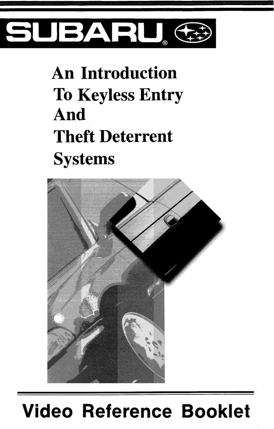
2 0 Copyright 1997 Subaru of America, Inc. All rights reserved. This book may not be reproduced in whole or in part without the express written permission of Subaru of America, Inc. Subaru of America, Inc. reserves the right at any time to make changes or modifications to systems, procedures, descriptions, and illustrations contained in this book without necessarily updating this document. Specifications included are accurate as they existed at the time of publication. Information herein is considered current as of December, Subaru of America. Inc. MSA5AV147B

3 ONTENTS INTRODUCTION... 3 svx... 4 Original SVX System (SOA386R120)... 4 Revised SVX System (SOA386R601)... 5 Front-Wheel Drive SVX System (SOA386R121)... 5 Dual Air Bag SVX System (SOA386R122) LEGACY... 6 Base System (SOA386R110)... 6 Mid-Level System (SOA386Rlll)... 7 High-Level System (SOA386R112) LSi... 9 Theft Deterrent. Factory Installed... 9 Keyless Entry System... 9 CODE ALARM SYSTEMS m Keyless Entry System Security System Upgrade INSTALLATION PROCEDURE LEGACY KEYLESS ENTRY SYSTEM Installing the Keyless Entry Control Module Programming the Keyless Entry Control Module Testing the Remote Keyless Entry System INSTALLATION PROCEDURE LEGACY THEFT DETERRENT SYSTEM Installing the Theft Deterrent System... Testing the Theft Deterrent System Finishing the Installation Procedure CONCLUSION Video Reference Booklet

4 This Video Reference Booklet accompanies the videotape "An Introduction to Keyless Entry and Theft Deterrent Systems." It summarizes the information contained in the videotape and includes additional information. This Booklet provides an overview of the keyless entry and theft deterrent systems used on: TheSVX The '94 Legacy The '97 LSi The Code Alarm System (used on the '98 Legacy, the '98 Impreza, and the 1998 Forester.) It also demonstrates how to install the Code Alarm keyless entry and theft deterrent systems on a 1997 Legacy. Security System Port'Deaier Active H7110FS.200 Yes Yes Yes Upgrade Switch and Control Module Only *' "No" indicates transmitter frequency not retained in memory after vehicle battery power is disconnected "Yes" indicates transmitter frequency retained in memory after vehicle battery power is disconnected '98 Keyless Entry and Theft Deterrent Systems Video Reference Booklet 3
 It also demonstrates how to install the Code Alarm keyless entry and theft deterrent systems on a 1997 Legacy. Security System Port'Deaier Active H7110FS.")
5 vx AN INTRODUCTION To KEYLESS ENTRY All SVX s sold in the U.S. are equipped with a theft deterrent system installed at the port. STARTER INTERRUPT RELAY 1 SVX Transmitters Original SVX System (SOA386R120) The first version is SOA386R120, designed for all-wheel drive SVX vehicles with a single driver s side air bag. It s a combination active and passive system. When the system is on and the doors and trunk are closed, the driver can actively lock the doors and arm the system by pressing the button on the remote transmitter. The security system also passively arms itself when it s on, 45 seconds after the driver exits from the vehicle and closes the doors and trunk lid. Note: the doors do not have to be locked. When the security system is Off, the transmitter operates the keyless entry system only. THEFT DETERRENT CONTROL MODULE I SVX Starter Interrupt Relay The original SVX theft deterrent system needs to be reprogrammed for the remote transmitters any time vehicle battery power is lost, for example when the battery is disconnected. When the vehicle s battery is reconnected, the parking lights flash and the theft deterrent control module clicks, to indicate that the system needs to be reprogrammed. To reprogram the system, press the button on one transmitter two times (while the parking lights are flashing), then press the other transmitter button twice, then press the button on the first transmitter once more - a total of five times. The system responds by turning on the parking lights each time the button is pressed. While the button is being pressed, the lights stay on and do not flash. Pressing the transmitters five times fills up all five memory slots in the theft deterrent control module. One unique feature of the original SVX system is that the system is On when the security button is out, and Off when the button is pushed in. 4 V SVXTheft Deterrent Control Module The components include the theft deterrent control module, located behind and above the glove box, and a starter interrupt relay, mounted on the right of the steering column. deo Reference Booklet SVX Security Switch

6 Revised SVX System (SOA386R601) In /2, the SVX theft deterrent system was revised to make the system more user friendly. In the revised system, the passive-arming feature is eliminated. The only way to arm the system is to press the button on the remote transmitters, or lock the driver s door with a key or with the inside door lock. Customers whose SVX s had the original theft deterrent system were invited to have the system upgraded by the dealer. The upgraded system includes a control module and a security system switch. SVXTheft Deterrent Control Module and Security System Switch, SOA386R601 This control module has a permanent memory, so the system only needs to be reprogrammed for a new transmitter - not when the vehicle battery has been disconnected. To reprogram this system, turn the security system Off. Put the key in the ignition switch and turn the ignition switch On then Off, two times. Then immediately push the security switch on and off rapidly until the horn starts to beep. Slowly press the button two times on each transmitter. The control module has four memory slots, not five. The parking lights flash each time a transmitter button is pushed, to indicate that the security system has recorded the transmitter frequency. Now cycle the ignition switch On then Off to exit from the programming mode. The new security system switch is a momentary-contact type. It blinks when the system is on, and is dark when the system is off. Front-Wheel Drive SVX System (SOA386R121) In 1994, a version of the SVX was introduced that was front-wheel drive; a different theft deterrent system was used on this vehicle. Front-wheel drive SVX s with a single air bag use the theft deterrent system SOA386R12 1. Dual Air Bag SVX System (SOA386R122) In 1994, dual air bags became optional on the SVX. On these vehicles, the theft deterrent control module was moved to the underside of the rear shelf. The theft deterrent system for SVX s with dual air bags is SOA386R122. Location of Theft Deterrent Control Module - SVX with Dual Air Bags Video Reference Booklet 5

7 LEGACY This vehicle has three levels of theft deterrent systems, all of which are port- or dealer-installed options. Base System (SOA386RllO) The base system, SOA386R110, is passive only; it does not have a remote transmitter. When the system is on and all the doors are closed, the system arms itself after 25 seconds. The doors do not have to be locked for the system to arm. The base security system includes a control module mounted on the steering column, and a valet switch/led mounted on the dash to the left of the steering column. The security system switch has three positions: Off, Shock Off, and On. In the Shock Off position, the security system is on, but the shock sensor is disabled; the theft deterrent system will sound the horn and flash the parking lights only when unauthorized entry or tampering occurs. When the switch is in the On position, the theft deterrent system will also activate when an impact is detected. If the impact is moderate, the system will activate the alarm for two seconds to warn away an intruder. If the impact occurs three times within seven seconds, or if the impact is extreme, the alarm will activate for two minutes. W Theft Deterrent Control Module Legacy VALET Valet Switch Legacy 6 Video Reference Booklei

8 m Mid-Level System (SOA386Rlll) For the next level of theft deterrent, SOA386Rl11, which is added to 110, the theft deterrent system can be actively armed and disarmed using the remote transmitters. It also passively arms itself when all doors are closed. Note that the transmitters only arm and disarm the theft deterrent system - they do not lock or unlock the doors. In addition to the base system components, the mid-level system includes a receiver and remote transmitters to arm and disarm the system. RemoteTransmitters (1990-'94 Legacy with Remote Theft Deterrent) 5Receiver Module '94 Legacy Video Reference Booklet 7

9 High-Level System (SOA386R112) The highest level of theft deterrent, SOA386R112, is added to 110 and 111. It provides keyless entry in addition to theft deterrent. The remote transmitters lock and unlock the doors as well as arming and disarming the theft deterrent system. In addition to the mid-level system components, the high-level system includes a door lock actuator as well as a module. Like the earliest SVX, the mid-level and high-level '94 Legacy systems must be reprogrammed any time vehicle battery power is lost. When vehicle battery power is restored, the parking lights flash at one second intervals to indicate the system is ready to be reprogrammed. To reprogram the system, press button one on one transmitter, and hold it for two seconds, then button two, then both buttons simultaneously. Then press button one on the other transmitter, then button two. Be sure to hold each button down for two seconds. Pressing the buttons in this sequence fills all five memory slots in the theft deterrent control module. DRIVER'S DOOR, UPPER REAR Door Lock Actuator '94 Legacy Keyless Entry Control Module '94 Legacy 8 Video Reference Booklet

10 L SI Theft Deterrent All LSi s sold in the U.S. are equipped with a factory-installed theft deterrent system. The system arms itself when the driver exits from the vehicle and locks the doors with a key, or when the driver locks the door with the door lock. The system includes a theft deterrent control module and a security system indicator LED. The LED is on steadily when the system is armed. Keyless Entry System The LSi has a port- or dealerinstalled optional keyless entry system manufactured by Code Alarm. The Code Alarm control module remembers the frequencies of the transmitters, after vehicle battery power has been disconnected. When battery power is restored, it may flash the parking lights, to ask whether the transmitters have changed. If it does, press the Lock button on the transmitter once, to indicate that the transmitters have not changed. To reprogram this system for new transmitters, with the ignition switch On, press and hold the programming button. After 15 seconds the door locks should cycle (or, on some vehicles, the relay in the control module will click). Continue pressing the programming button. With your other hand, press the Lock button on one of the transmitters, twice, then press the Lock button on the other transmitter twice. This will fill up the four memory slots in the theft deterrent control module with the frequencies of the two transmitters. Theft Deterrent Control Module LSi Security System Indicator (LED) LSi RemoteTransmitter LSi with Keyless Entry Programming button LSi Video Reference Booklet 9

11 The Code Alarm systems are port- or dealer-installed options. They are used on the Legacy, the Impreza, and the 1998 Forester. The base system provides keyless entry; theft deterrent is an upgrade. There are different kits for different carlines; see the Keyless Entry and Vehicle Security Systems Installation Reference Guide for details. Keyless Entry System The keyless entry system kit has a control module, two remote transmitters, and a harness. For the 1997 Impreza, the keyless entry system kit includes a door lock actuator, since the driver s door does not come equipped with an electric actuator. Security System Upgrade The security system upgrade kit includes a shock sensor, a siren, a valet button and LED indicator and additional harnesses. It s an active system - it can be armed only with the transmitters Legacy Keyless Entry Kit, Code Alarm H7110AS lmpreza Keyless Entry Kit, Code Alarm H7110FSOOO Legacy Security System Kit, Code Alarm H7110AS Video Reference Booklet

12 I997 LEGACY KEYLESS ENTRY SYSTEM NSTALLATION PROCEDURE - Installation on the 1997 and 98 Impreza and 1998 Forester is much easier because the vehicles are pre-wired for the Code Alarm system - all you have to do is plug in the wire connectors. With the 1995 to 1997 Legacy and some 1998 Legacys, you will have to splice some wires. Installing the Keyless Entry Control Module Whenever working on a keyless entry system, be sure to lower the driver s side window, so you don t accidentally lock the keys in the vehicle. Remove the driver s side rockedkick panel molding, and remove the lower left dash trim to access the wiring. Plug the wiring harness into the remote keyless entry module and remove the 20-amp fuse from the yellow wire with a green trace. To connect the module to battery power and switched power, first locate the gray 12-pin connector B-52 in the fuse box. I WIRE END VIEW OF CONNECTOR I\ REDBLACK YELLOWiGREEN In most cases, the keyless entry module s wire colors match the colors of the vehicle s wires that they splice with. But be careful to connect the wires correctly - mistakes are easy to make, and the system won t work if the connections are wrong! Using one of the red quicksplice connectors supplied in the keyless entry kit, connect the module s yellow/green wire Using a Quick-Splice Connector to the vehicle s yellow/green wire, which provides constant power. Put the quick-splice connector on the module s wire first, using pliers to make sure the connector cuts through the insulation. Then attach the quick splice connector on the vehicle s yellow/green wire, approximately 1 in. from the vehicle connector. Wrap the splice with electrician s tape to secure it. Splice the module s red/black wire to the vehicle s red/black wire, which provides switched power; this splice should also be made 1 in. from the vehicle connector. Note: there are two red/black wires; be sure to splice to the correct one! Fuse Box Connector B-52 Module s White Wire Connected Lllt: lcll slut: Ul the steering to Ground column. Video Reference Booklet 77

13 AN INTRODUCTION TO KEYLESS ENTRY Now connect the module to the parking lights. Locate the gray 15-pin connector, I- 5 in the fuse box. Using a quick-splice connector, connect the module s white/yellow wire to the vehicle s white/yellow wire, 1 in. from the vehicle connector. Now, connect the module to the courtesy lights. Locate the black 22-pin connector B-36 above the hood lock release lever and unplug it. Splice the module s rediwhite wire to the vehicle s red/white wire, 1 in. from the connector, and plug the connector back into the connector block. Now, connect the module to the door locks. Locate the 8-pin connector B-92 plugged into the door lock timer. Splice the module s white/red wire to the vehicle s white/red wire, 1 in. from the connector. Splice the module s white wire to the vehicle s white wire. 1 in. from the connector. D VIEW OF CONNECTOR - w WHITE~YELLOW 1-5 Fuse Box Connector 1.5 Connector B-36 Connector Video Reference Booklet

14 receive the transmitter frequencies. With the ignition switch On and the engine not running, insert the 20-amp fuse in the holder on the yellow/green wire. in. from the Connector D-8 r e d / g r e e n Butt-Splicing RedlGreen Wire on wire. ~~k~ Module to Vehicle s RedlGreen sure the cor- Wire and PinklGreen Wire to Vehicle s RedlGreen Wire rect wires are butt-spliced together or the keyless entry module or the door lock control module may be damaged, or the door lock fuse may be blown. Butt-splice the red/green wire on the vehicle interior side of the cut to the module s pinwgreen wire. Use elec- tor support, Label on Radiator Support and the label with small lettering to the negative battery cable. Programming the Keyless Entry Control Module Once the keyless entry control module is installed, you will need to program it to With the driver s door open, press and hold the programming button on the wiring harness. After 15 seconds, the door locks will cycle to indicate the system is in the programming mode. Do not release the programming button. Press the Lock button twice on one of the transmitters. The door lock actuators will operate each time a button is pressed to confirm programming. Repeat this step for the other transmitter. Then release the programming button and turn the ignition switch Off. Testing the Remote Keyless Entry System To test the keyless entry system, first close all vehicle doors; the dome light switch should be set to the Door position. Press the Lock button on one of the remote transmitters. The vehicle doors should all lock, the courtesy light should turn off, and the parking lights should flash once. Press the Unlock button on one of the transmitters. The driver s door should unlock, the courtesy lights should turn on, the and parking lights should flash once. Press and hold the Unlock button on the same transmitter. The other doors should unlock. Now, repeat the procedure with the other transmitter. If the keyless entry system responds incorrectly, check the installation. Video Reference Booklet 13

15 NSTALLATION PROCEDURE - Once the Code Alarx keyless entry system has been installed, the theft deterrent system can be added. Begin by removing both 20-amp fuses from the keyless entry wire harness and unplugging the harness wire connectors from the keyless entry control module. Adding the theft deterrent system does not require a second control module; the electronic controls for the system are already in the keyless entry module. The additional components required are the shock sensor, the siren, the starter interrupt harness, the valet button/led indicator, and the dome lamp wire loop. IS97 LEGACY THEFT DETERRENT SYSTEM Installing the Theft Deterrent System Install the siren on the passenger side shock tower, using the existing 10 mm bolt. The bell housing should face downward and should not touch any other components. On newer models, the bell housing of the siren may contact the A/C line. If it does, carefully reposition the A/C line. Be sure to wear appropriate safety equipment when performing this procedure. Tape the ends of the siren wiring harness to prevent damage to the tips when the harness is being installed. Siren Route the siren wires under the brake proportioning valve to the harness grommet on the driver s side bulkhead. Remove the grommet from the access hole a.nd pierce it. Thread the siren wires through the grommet. Pierce the bulkhead insulation and pass the siren wires through the bulkhead panel and into the passenger compartment. Reinstall the grommet. Apply silicone to seal the grommet. Harness Grommet - Driver s Side Bulkhead 74 Video Reference Booklet

16 BLACK ORANGE E I I9 I8 I I1 I RED WIRE END VIEW OF CONNECTOR Now install the valet button and LED indicator. Using a small screwdriver, remove the dash blank, being careful not to damage the instrument cluster bezel, and install the valet button and LED indicator to the left of the steering wheel. 18-Pin Keyless Entry Control Module Connector Plug the red wire from the siren into the wire side of cavity 2 of the 18-pin keyless entry control module connector and the black wire into cavity 16. Next, install the starter interrupt harness. Unplug the black 6-pin vehicle ignition connector B-72 to the right of the steering column, and plug the starter interrupt harness into both connectors of the harness. Valet ButtonlLED Indicator Route the wires to the keyless entry module and plug the wires into the wire end side of the 18-cavity connector. The blue wire goes in cavity 13, the green wire in cavity 14, and the orange wire in cavity 15. Next unravel the wire to the programming button on the keyless entry harness. Insert the button in the square hole in the metal bracket behind the hood release lever. Use the button housing to secure it. Starter Interrupt Harness Connected into Vehicle Ignition Connector, 8-72 Route the free end of the starter interrupt harness to the keyless entry module and plug the 2-pin connector from the harness into the 2-pin receptacle in the keyless entry module. Secure the harness with tiewraps. Programming Button Inserted into Metal Bracket Behind Hood Release Lever Video Reference Booklet 15

17 Shock Sensor Attached to Metal Bracket on Right of Steering Column Stick the self-adhesive pad on the back of the shock sensor housing. Attach the shock sensor to the metal bracket on the right side of the steering column. The sensor should be mounted with the side labeled Sensor facing downwards, and the harness end pointing toward the rear of the vehicle. Secure the sensor with a tie wrap. Plug the 4-pin shock sensor connector into the 4-pin receptacle on the keyless entry module. Next, remove the 2-pin jumper for the dome lamp wire loop on the keyless entry harness and discard it. Plug the dome lamp wire loop supplied in the kit into both connectors on the harness. Plug the 18-pin and 5-pin connectors into the keyless entry module. With the ignition switch On, insert both 20-amp fuses into the keyless entry harness and turn the ignition switch Off. Be sure to do this as the last step, before testing the system. Connecting 4-Pin Shock Sensor into Keyless Entry Module Dome Lamp Wire Loop (Connected) Connecting 18-Pin and 5-Pin Connectors into Keyless Entry Module 16 Video Reference Booklet

18 Testing the Theft Deterrent System Exit from the vehicle and close all the doors. Press the Lock button on the remote transmitter. The doors should lock; if they don t check the door lock connections. The siren should chirp twice and the parking lamps should flash twice. If they don t make sure all doors are closed. The status indicator should flash at a steady rate (about once per second). If it doesn t, but the siren chirps twice, check the indicator connections. If the status indicator does not flash and the siren does not chirp, make sure all doors are closed. Open the vehicle door. The siren should sound and the parking lights should flash. If they don t, check the dome light connections. Also, the status indicator should flash quickly. With the alarm sounding, try starting the engine; the engine should not start. If it does, make sure the emergency override (programming) button is not pressed in. Press the Unlock button on the transmitter to disarm the system. Attempt to start the engine. The siren and parking lights should stop, the driver s door should unlock, and the engine should start. If not, check the ignition switch connections. Press both the Lock and Unlock buttons simultaneously. The panic alarm should sound. Press either button to turn it off. With the ignition switch Off, press and release the status indicatorhalet button. The indicator should begin flashing in a quick double-flash pattern (valet mode). Pressing the transmitter buttons will lock and unlock the doors, with the siren and the parking lights emitting one pulse, but the system will not arm. Press the valet button again to exit from the valet mode. Close all the doors. With the driver s window down, arm the system and wait 10 seconds. Reach inside the vehicle and hit the rim of the steering wheel firmly. (Do not hit the horn or the air bag!) The alarm should sound. Press the Unlock button to stop the alarm. If it does not sound, adjust the sensitivity of the shock sensor (See the Keyless Entry and Vehicle Security Systems Installation Reference Guide for the procedure.) Close all the doors. With the driver s window down, arm the system and wait 10 seconds. Then trigger the system by opening a door, from inside, by reaching into the vehicle. The siren should sound. Turn the ignition switch to the On position, then press the emergency override button. The alarm will shut off. If the siren does not sound, or does not go off when the emergency override button is pushed, check the button and wiring. Video Reference Booklet 17

19 Finishing the installation Procedure One the system has been completely tested, mount the keyless entry module with the connectors facing upward in the area above the fuse box, and secure it with tie wraps. Put the window decals on the inside of the rear passenger windows at the lower front edge of each window. Mounting the Keyless Entry Module Window Decal 18 Video Reference Booklei

20 To KEYLESS ENTRY AN INTRODUCTION Be sure to use the Keyless Entry and Ve h i c 1 e Se c u r i ty Systems Ins ta 11 at ion Reference Guide and this Video Reference Booklet, and you will be able to program the SVX, Legacy, and Code Alarm systems, and install the Code Alarm systems. Service Bulletins and Helpline Updates svx SB SVX Security System Precaution SB SVX Security System (Main Switch) HU SVX Security System HU 1-92 Warning SVX Security System HU 2-92 LED Interpretation HU SVX New Security System Installation Tips HU Legacy and SVX Security System Transmitter Battery Servicing HU Security System in 1997 SVX with Dual SRS System Legacy HU 4-92 Legacy Security System Wiring Information HU HU Legacy Security System Operation Q&A LSI HU Legacy Security System HU Legacy LSi Security System HU Legacy LSi Security Systems Module Hi Subaru Legacy LSi Alarm System HU Legacy Remote Keyless Entry System HU 1-96 Legacy Keyless Entry Diagnosis Legacy Accessory Keyless Entry System HU Legacy Keyless Entry Video Reference Booklet 19

21 Mark your answers to the following questions and mail the quiz to Subaru Video Training Program Headquarters. Name Dealer Dealer Code 1. The original SVX theft deterrent system is... a. Active only. b. Passive only. c. Active and passive. d. None of the above. 2. The original SVX theft deterrent system needs to be reprogrammed for the remote transmitters: a. When a transmitter battery is replaced. b. Any time vehicle battery power is lost. c. Only when a transmitter is replaced. d. None of the above. 3. The original SVX theft deterrent system is Off when the security button is out, and On when the button is pushed in. a. True b. False 4. The revised SVX theft deterrent system, introduced in 1993, is.., a. Active only. b. Passive only. c. Active and passive. d. None of the above. 5. The revised SVX theft deterrent system is. a. Off when the switch is out, and On when the switch is pushed in. b. On when the switch is out, and Off when the switch is pushed in. c. On when the switch s LED is dark, and Off when the switch s LED blinks. d. Off when the switch s LED is dark, and On when the switch s LED blinks. 6. The base theft deterrent system on a Legacy is... a. Active only. b. Passive only. c. Active and passive. d. None of the above. 7. The mid-level theft deterrent system on a Legacy includes... a. Keyless entry only. b. Remote arming and disarming only. c. Both keyless entry and remote arming/disarming. d. None of the above. 8. The mid-level and high-level Legacy theft deterrent systems need to be reprogrammed: a. When a transmitter battery is replaced. b. Any time vehicle power is lost. c. Only when a transmitter is replaced. d. None of the above. 9. The theft deterrent system on a LSi arms itself When the driver exits from the vehicle and locks the doors with a key. b. When the driver locks the door with a door lock. c. When the driver presses the Lock button on the remote transmitter, on LSi s equipped with keyless entry. d. All of the above. 10. With the Code Alarm systems for the Impreza, Legacy, and 1998 Forester, the keyless entry control module includes the electronics for theft deterrent. a. True b. False 20 Video Reference Booklet. z
1R / 4-BUTTON SERIES
 Button 1 1R / 4-BUTTON SERIES VEHICLE SECURITY SYSTEM Standard Features: Two 4-Button Remote Transmitters Status indicator (LED) Valet / override switch Multi-tone siren Dual stage impact detector Remote
2003/2004/2005 TOYOTA COROLLA
 2003/2004/2005 TOYOTA COROLLA KEYLESS ENTRY UPGRADE SECURITY SYSTEM INSTALLATION INSTRUCTIONS KIT NO. 00016-30120 SPECIAL NOTE: Installation Sequences After TMS and Safety mandated preparatory steps have
KEYLESS ENTRY UPGRADE SECURITY SYSTEM for 2004 TOYOTA HIGHLANDER
 KEYLESS ENTRY UPGRADE SECURITY SYSTEM for 2004 TOYOTA HIGHLANDER DEALER SERVICE AND INSTALLATION MANUAL KIT NO. 00016-30915 Contents PARTS LIST... 2 PARTS ILLUSTRATIONS... 2 VEHICLE PREPARATION... 3 INSTALLING
PRO PLM Installation Instructions
 PRO PLM Installation Instructions PROFESSIONAL INSTALLATION STRONGLY RECOMMENDED Installation Precautions: Roll down window to avoid locking keys in vehicle during installation Avoid mounting components
Multi Function, User Configurable Remote Vehicle Security System with 4 Button Replaceable Membrane Remote Transmitter
 MODEL PRO-9744 INSTALLATION MANUAL Multi Function, User Configurable Remote Vehicle Security System with 4 Button Replaceable Membrane Remote Transmitter This System Allows The Transmitter Buttons To Be
INSTALLATION MANUAL 3RP / 5RP 4-BUTTON SERIES VEHICLE SECURITY SYSTEMS
 3RP / 5RP 4-BUTTON SERIES VEHICLE SECURITY SYSTEMS INSTALLATION MANUAL Before you begin the installation Read the INSTRUCTIONS! Always use a multi-meter when verifying vehicle wiring. Before mounting the
Installation Instructions
 Installation Instructions for EVS II Security and Keyless Entry Systems Note: It is recommended that this installation take place prior to rustproofing. The individual delivering the vehicle should review
VEHICLE SECURITY SYSTEM G25/G20
 VEHICLE SECURITY SYSTEM G25/G20 Limited Lifetime Warranty This vehicle security system is warranted to the original purchaser, to be free from defects in material and workmanship. The manufacturer will
INSTALLATION GUIDE OWNER S GUIDE
 INSTALLATION GUIDE OWNER S GUIDE SECURITY SYSTEM PRO-SERIES 5002 CONTENTS System Features... 1-2 System Components... 2 Technical Assistance... 2 Before You Begin... 2 Precautions... 2-3 Making Connections...
How To Control A Car Alarm On A Car With A Remote Control System
 MODEL CA100 REMOTE CONTROL AUTO ALARM SYSTEM INSTALLATION & OPERATION INSTRUCTIONS WIRING DIAGRAM Black Antenna Wire 6 Pin 6 Pin Mini Connector Valet Switch Blue LED Indicator Blue Wire: (-) 200mA Unlock
Car Alarm Series 2 B 2 Buttons
 Car Alarm Series 2 B 2 Buttons G22 SE (External - Shock Sensor) Version 3 Software 67 Plus www.geniuscaralarm.com 21 CAR ALARM GENIUS Series 2B 2 Buttons - G22 Se (External Shock Sensor) Module controlled
ANTI-THEFT SYSTEM. 1995 Volvo 850 DESCRIPTION & OPERATION BASIC ALARM. 1995-96 ACCESSORIES & EQUIPMENT Volvo Anti-Theft Systems
 ANTI-THEFT SYSTEM 1995 Volvo 850 1995-96 ACCESSORIES & EQUIPMENT Volvo Anti-Theft Systems 850 DESCRIPTION & OPERATION WARNING: Deactivate air bag system before performing any service operation. For 1995
INSTALLATION MANUAL VEHICLE SECURITY SYSTEM CE-SS200
 INSTALLATION MANUAL VEHICLE SECURITY SYSTEM CE-SS200 FUSION CULTURE TABLE OF CONTENTS There s no point doing something if no one notices. We ve always believed the way to make things happen is by getting
HONDA ACCORD 1985-2005
 HONDA ACCORD 1985-2005 VEHICLE WIRING Copyright 2002-2004 Triple S Customs WIRING INFORMATION: 1985 Honda Accord WIRE WIRE COLOR WIRE LOCATION 12V CONSTANT WHITE or WHITE/BLACK Ignition Harness STARTER
Button 1 Button 2. Button 3 Button 4. Programmed Remote Transmitter. Button Function Condition
 WWW.STELLAR.COM ST9000 SECURITY SYSTEM Button Function Condition 1 a. Arm and lock doors b. Car finder with sound c. Temporary stop alarm from sounding d. Remote lock doors 1 for 2 sec. Panic Anytime a.
SP-100 REMOTE CONTROL ALARM SYSTEM INSTALLATION & OPERATING INSTRUCTIONS INTRODUCTION
 SP-100 REMOTE CONTROL ALARM SYSTEM INSTALLATION & OPERATING INSTRUCTIONS INTRODUCTION CONGRATULATIONS on your choice of a Security Plus Remote Alarm System by Crimestopper Security Products Inc. This booklet
WIRING HARNESS FOR AS635P4. BLUE PLUG RED, BLUE, BLACK, WHITE - Plug in dual stage sensor harness
 WIRING HARNESS FOR AS635P4 ANTENNA NOT USED 5 PIN WHITE PLUG 2 PIN WHITE PLUG GREEN - PARKING BRAKE INPUT (-) BLUE - NOT USED 3 PIN BLUE PLUG RED, BLUE, BLACK, WHITE - Plug in dual stage sensor harness
Keys... 2-2 Master, submaster and valet key... 2-2 Key number... 2-2. Door locks... 2-3 Power door locking switches... 2-5
 Doors and locks Keys........................................................................... 2-2 Master, submaster and valet key..................................... 2-2 Key number...............................................................
INSTALLATION INSTRUCTIONS
 INSTALLATION INSTRUCTIONS Accessory Application Publications No. AII 26327 2004 S2000 Issue Date OCT 2004 PARTS LIST Security System: P/N 08E51-S84-100 Attachment Kit: P/N 08E55-S2A-101 2 Remote controls
INSTALLATION INSTRUCTIONS
 INSTALLATION INSTRUCTIONS Accessory Application Publications No. AII23628 2003 PILOT Issue Date MAY 2002 PARTS LIST Security System Kit (sold separately): P/N 08E51-S84-100 2 Remote controls Attachment
How To Set Off An Alarm On A Car With A Car Alarm On It
 AUTO SECURITY SYSTEM USER S OPERATION GUIDE FCC ID NOTICE This device complies with Part 15 of the FCC rules. Operation is subject to the following conditions: 1. This device may not cause harmful interference,
VEHICLE THEFT/SECURITY SYSTEMS
 DN VEHICLE THEFT/SECURITY SYSTEMS 8Q - 1 VEHICLE THEFT/SECURITY SYSTEMS TABLE OF CONTENTS page GENERAL INFORMATION INTRODUCTION...1 VEHICLE THEFT SECURITY SYSTEM....1 ENABLING...1 ARMING...1 DISARMING...2
REMOTE START SECURITY SYSTEM OWNERS MANUAL
 REMOTE START SECURITY SYSTEM OWNERS MANUAL Standard Features The System has the following standard features: 5-button remote transmitter Status indicator (LED) Valet/Service mode switch Remote Start capabilities
Vehicle Alarm System With Channel 2 Auxiliary Output Installation Instructions
 Model PRO 9842 Installation Manual Vehicle Alarm System With Channel 2 Auxiliary Output Installation Instructions This Unit Is Intended For Installation In Vehicles With 12 Volt Negative Ground Electrical
VEHICLE THEFT/SECURITY SYSTEM
 PL VEHICLE THEFT/SECURITY SYSTEM 8Q - 1 VEHICLE THEFT/SECURITY SYSTEM TABLE OF CONTENTS page DESCRIPTION AND OPERATION INTRODUCTION...1 VEHICLE THEFT/SECURITY SYSTEM (VTSS)... 1 (SKIS)... 2 SENTRY KEY
Remote Access System Installation
 2011-2013 Explorer Remote Access Remote Access System Installation CONTENTS VEHICLE PREPARATION Hood Switch Wire Harness Installation Hood Switch Installation RMST Module Installation RMU Module Installation
SECURITY SYSTEM OWNER S MANUAL MIATA, MAZDASPEED MX-5
 SECURITY SYSTEM OWNER S MANUAL MIATA, MAZDASPEED MX-5 Introduction l l l l l l l l l l l l l l l l Thank you for purchasing the Mazda Security Upgrade package. This system is designed to enhance the security
SNIPER X1 VEHICLE SECURITY SYSTEM
 SNIPER X1 VEHICLE SECURITY SYSTEM Installation Manual Table of Contents 1. FEATURES & SPECIFICATIONS... 2 2. TRANSMITTER BUTTONS:... 2 3. FUNCTION... 2 3.1 Key Function:...2 3.2 Remote Transmitter Code
ODYSSEY. Security System Owner s Manual. Kit No. 08E51-SHJ-100 08E55-SHJ-100. 2004 American Honda Motor Co., Inc. - All Rights Reserved.
 Kit No. 08E5-SHJ-00 08E55-SHJ-00 Security System Owner s Manual ODYSSEY 004 American Honda Motor Co., Inc. - All Rights Reserved. Contents Introduction... 3 Emergency Disarming During the Panic Alarm Activation...
INSTALLATION GUIDE OWNER S GUIDE
 INSTALLATION GUIDE OWNER S GUIDE TALKING ALARM MODEL 3001 CONTENTS System Features... 1 Technical Assistance... 1 Wiring Instructions... 2 Installation Instructions... 3 Operating Instructions... 4-5 Technical
INSTALLATION GUIDE. www.security.soundstream.com FCC ID NOTICE
 AL.1 AUTO SECURITY SYSTEM INSTALLATION GUIDE www.security.soundstream.com FCC ID NOTICE This device complies with Part 15 of the FCC rules. Operation is subject to the following conditions: 1. This device
VEHICLE SECURITY SYSTEM OPERATOR'S INSTRUCTIONS
 :). VEHICLE SECURITY SYSTEM OPERATOR'S INSTRUCTIONS (8 I NS070S Rev. A 12195 ThIs product is protected by U.S. patent number 5,049,867. @ Code Alarm, Inc. 1994 All rights reserved. Printed in the USA.
OPERATING INSTRUCTIONS SECURITY SYSTEM KIT NO.: 08E51-EP4-101. 2004 American Honda Motor Co., Inc. - All Rights Reserved. 1
 OPERATING INSTRUCTIONS SECURITY SYSTEM KIT NO.: 8E5-EP4-24 American Honda Motor Co., Inc. - All Rights Reserved. Contents Introduction... 3 Emergency Disarming During Alarming... 4 During the Entry Delay
INSTALLATION GUIDE OWNER S GUIDE
 INSTALLATION GUIDE OWNER S GUIDE KEYLESS ENTRY MODELS KE100 / KE150 / 1702 CONTENTS System Features... 1 System Components... 1 Technical Assistance... 1 Before You Begin... 1 Precautions... 1-2 Making
e-ask electronic Access Security Keyless-entry
 e-ask electronic Access Security Keyless-entry e-fob Keyless-entry entry System Full-Function Function Installation Manual FCC ID: TV2EFOB1 (UM20 ~ 22793-02) Table of Contents Introduction... 1 e-fob Operation
i ChatterBox! Motorcycle Security
 i Before you Start the Installation * Please read this manual to become familiar with the requirements necessary to complete the installation. * Use a high quality multi-meter to test all wires before
Using your LED Plus keypad
 Using your LED Plus keypad System 238 System 2316 System 238i System 2316i Part Number 5-051-372-00 Rev B Thank you for purchasing this C&K alarm system Your system is one of the most powerful and advanced
TOYOTA TACOMA 2008- HANDS FREE BLU LOGIC Preparation
 TOYOTA TACOMA 2008- HANDS FREE BLU LOGIC Preparation Part #: PT923-00112 Conflicts: JBL Audio, Factory Navigation NOTE: Part number of this accessory may not be the same as the part number shown. Kit Contents:
MODELS 8007 Gorilla Cycle Alarm 8017 Gorilla Cycle Alarm with 2-way pager system 1018 2-way pager system
 MODELS 8007 Gorilla Cycle Alarm 8017 Gorilla Cycle Alarm with 2-way pager system 1018 2-way pager system Remote Control Motorcycle Alarm System Installation & Operation Instructions Sistema de Alarma de
LAND ROVER MANUAL CONTENTS APPLICATIONS GENERAL OPERATION SPECIAL FUNCTIONS REMOTE CONTROL PROGRAMMING
 LAND ROVER LAND ROVER MANUAL CONTENTS APPLICATIONS GENERAL OPERATION SPECIAL FUNCTIONS REMOTE CONTROL PROGRAMMING APPLICATIONS VEHICLE SYSTEM YEAR CABLE CLASSIC RANGE ROVER 10AS 95 ON ADC110-B DEFENDER
2004 Directed Electronics, Inc. Vista, CA N426V 07-04
 350HV Installation Guide NOTE: This product is intended for installation by a professional installer only! Any attempt to install this product by any person other than a trained professional may result
535T Window Automation System
 535T Window Automation System Installation Guide NOTE: This product is intended for installation by a professional installer only! Any attempt to install this product by any person other than a trained
Security and Remote Start Installation Guide for models: CA 6150 CA 6550
 PROFESSIONAL SERIES Security and Remote Start Installation Guide for models: CA 6150 CA 6550 2009 Audiovox Electronics Corporation. All rights reserved. 1 Table of Contents Before You Begin... 4 Wire Connection
MODELS 7007 Gorilla Cycle Alarm 7017 Gorilla Cycle Alarm with 2-way pager system 1017 2-way pager system
 MODELS 7007 Gorilla Cycle Alarm 7017 Gorilla Cycle Alarm with 2-way pager system 1017 2-way pager system Remote Control Motorcycle Alarm System Installation & Operation Instructions Sistema de Alarma de
Model AM2. Installation Guide
 Model AM2 Installation Guide NOTE: This product is intended for installation by a professional installer only! Any attempt to install this product by any person other than a trained professional may result
INSTRUCTION MANUAL FOR. Remote Control Car Alarm with Impact Sensor, Mini-Battery Backup Siren & Engine Immobiliser
 INSTRUCTION MANUAL FOR Remote Control Car Alarm with Impact Sensor, Mini-Battery Backup Siren & Engine Immobiliser A.C.N 001 621 610 SYDNEY / AUSTRALIA Build Date: TO ARM/DISARM ALARM The alarm is activated
The Child Reminder System Installation Manual
 The Child Reminder System Installation Manual Revised June, 2006 Detailed installation information can be found at www.childreminder.com. Get through your installation quickly and easily by calling 1-888-330-6786
AVS A4 alarm Owner s manual
 AVS A4 alarm Owner s manual Thank you for choosing an AVS A4 car security system. It has been designed to provide a superior level of security for you and your vehicle. Please read this guide carefully
CA-125 Owner's Manual
 Remote Vehicle Control System CA-125 Owner's Manual Vehicle Security System With Remote Keyless Entry IMPORTANT NOTE: The operation of the Security and Convenience System as described in this manual is
REMOTE TRANSMITTER LAYOUT
 Full Featured Keyless Entry System with Optional Starter Defeat and Passive Immobilize Feature SYSTEM MANUA STANDARD FEATURES Some of the system s standard features include: Two 4-button remote transmitters
Copyright 2002-2004 Triple S Customs
 CHEVROLET SILVERADO 1988-2005 VEHICLE WIRING Copyright 2002-2004 Triple S Customs WIRING INFORMATION: 1988 Chevy Silverado Full-Size 2- POWER DOOR LOCK (5-wire reverse polarity) POWER DOOR UNLOCK (5-wire
MotorCycle Alarm by DEF COM 3 INSTALLATION MANUAL 80 C
 DEF COM 3 INSTALLATI MANUAL MotorCycle Alarm by IMMOBILISER (FAIL SAFE SYSTEM) Positive Logic (the relay switches over when the central unit is disarmed and ignition +15 is present.) Fig.2 Fig.3 SUPPLEMTARY
VEHICLE SECURITY SYSTEM Optional Remote Start Module and 2-way Transmitter Instructions Included
 VEHICLE SECURITY SYSTEM Optional Remote Start Module and 2-way Transmitter Instructions Included STANDARD FEATURES Some of the system s standard features include: 4-button remote transmitter LED Status
TOYOTA PRIUS 2010- HANDS FREE BLU LOGIC Preparation
 TOYOTA PRIUS 2010- HANDS FREE BLU LOGIC Preparation Part #: PT923-00111 Conflicts: JBL Audio, Factory Navigation NOTE: Part number of this accessory may not be the same as the part number shown. Kit Contents:
PATENTED: www.voxxintl.com/company/patents
 Model PRO9776C Installation Manual Vehicle Security System Table Of Contents: with Remote Start Before You Begin Page 2 Wire Harnesses Quick View Page 3-4 Installation of the Major Components Page 5 Wiring
PATENTED: www.voxxintl.com/company/patents
 Model APS-997C Installation Manual 2 Way LCD Vehicle Security and Table Of Contents: Remote Start System Before You Begin Page 2 Wire Harnesses Quick View Page 3 and 4 Installation Of The Major Components
INSTALLATION INSTRUCTIONS
 INSTALLATION INSTRUCTIONS Accessory Application Publications No. ACCORD All 30209 2-AND 4-DOOR SYSTEM (VP, LX, SE) Issue Date AUG 2005 PARTS LIST Security System Attachment: P/N 08E55-SDA-100A Unit panel
INSTALLATION INSTRUCTIONS
 INSTALLATION INSTRUCTIONS Accessory Application Publications No. All 24393 ACCORD (DX, LX) SYSTEM 2-AND 4-DOOR Issue Date AUG 2002 PARTS LIST Security System Attachment (LX): P/N 08E55-SDA-100A Unit panel
VEHICLE SECURITY SYSTEM. Car Alarm System With Command Confirmation
 VEHICLE SECURITY SYSTEM Car Alarm System With Command Confirmation About Your System Congratulations on your purchase of this state-of-the-art vehicle security system. With proper installation this system
RF-350 PROFESSIONAL VEHICLE SECURITY SYSTEM WITH KEYLESS ENTRY. INSTALLATION & USERS MANUAL (For Authorized Dealers Only)
") RF-350 PROFESSIONAL VEHICLE SECURITY SYSTEM WITH KEYLESS ENTRY INSTALLATION & USERS MANUAL (For Authorized Dealers Only) Please register your product at www.autopageusa.com THIS PRODUCT IS DESIGNED FOR
RF-350 PROFESSIONAL VEHICLE SECURITY SYSTEM WITH KEYLESS ENTRY INSTALLATION & USERS MANUAL (For Authorized Dealers Only) Please register your product at www.autopageusa.com THIS PRODUCT IS DESIGNED FOR
Wireless Home Security Alarm System AM 500
 Wireless Home Security Alarm System AM 500 12 MONTH GUARANTEE Installation & Operating Instructions INTRODUCTION The AM500 is a simple self-contained alarm system. It protects the home by sounding a siren
GENUINE PARTS INSTALLATION INSTRUCTIONS
 GENUINE PARTS INSTALLATION INSTRUCTIONS DESCRIPTION: Illuminated Kick Plate APPLICATION: Rogue (2011) PART NUMBER: 999G6 GX010 KIT CONTENTS: Item A B C G H QTY 1 1 1 D 1 E 1 F 3 15 6 Description Kick Plate,
MAGICAR M871A. Car alarm with two-way remote User s guide
 MAGICAR M871A Car alarm with two-way remote User s guide EN MAGICAR M871A Car alarm with two-way remote User s guide TABLE OF CONTENTS Table of contents...2 1. Important notice...4 2. Introduction...4
ASTRA 4000RS/1000RS-DBP G55 SERIES VEHICLE SECURITY SYSTEM WITH REMOTE START PRODUCT MANUAL
 ASTRA 4000RS/1000RS-DBP G55 SERIES VEHICLE SECURITY SYSTEM WITH REMOTE START PRODUCT MANUAL Limited Lifetime Warranty This vehicle security system is warranted to the original purchaser, to be free from
WIRELESS HOME ALARM SYSTEM (WHA1)
") WIRELESS HOME ALARM SYSTEM (WHA1) IMPORTANT : PLEASE READ THIS MANUAL CAREFULLY BEFORE ATTEMPTING TO INSTALL AND OPERATE THIS ALARM SYSTEM. SAFETY Please note: Before you start to install this alarm, we
WIRELESS HOME ALARM SYSTEM (WHA1) IMPORTANT : PLEASE READ THIS MANUAL CAREFULLY BEFORE ATTEMPTING TO INSTALL AND OPERATE THIS ALARM SYSTEM. SAFETY Please note: Before you start to install this alarm, we
Keys... 1-2 Master, submaster and valet key... 1-2 Key number... 1-2
 Keys........................................................................... 1-2 Master, submaster and valet key..................................... 1-2 Key number...............................................................
SECURITY SYSTEM ADP-CAN
 INSTALLATION INSTRUCTION SECURITY SYSTEM ADP-CAN Introduction Motorcar security system ADP-CAN is for motorcars provided with CAN net. It is for the work with the motorcar factory security systems or remote
OWNER S OPERATION GUIDE English
 OWNER S OPERATION GUIDE English 76E268-0030-0606S -1- Printed in Japan Important WARNING / CAUTION / NOTE Please read this manual and follow its instructions carefully. To emphasize special information,
Networkfleet 3500 Product Line Installation Guide
 Networkfleet 3500 Product Line Installation Guide Light/Medium Duty (L3500) Heavy Duty (H3500) Universal (U3500) www.networkcar.com/fleet Customer Care: (866) 227-7323 [email protected] Table
Trailblazer, Envoy, Rainier, Ascender
 6. After removing the trim plate bezel simply remove the four ¼ screws holding the instrument cluster in place. Pull the cluster out and unplug the single wiring harness connection in the back. Trailblazer,
CA 1050 Owner s Guide
 PROFESSIONAL SERIES CA 1050 Owner s Guide Vehicle Security and Keyless Entry System IMPORTANT NOTE: The operation of the Security and Convenience System as described in this manual is applicable to most
Installation of Rear View Camera in a 1995 Roadtrek 190 Popular
 Installation Instructions: 1995 Roadtrek Rear View Camera Page 1 Installation of Rear View Camera in a 1995 Roadtrek 190 Popular Introduction. In the fall of 2010 we investigated rear view cameras for
SECURITY SYSTEM SMART SIREN KIT
 -J00876 REV. 009-0-09 SECURITY SYSTEM SMART SIREN KIT GENERAL Kit Number 688-0 Models For model fitment information, see the P&A Retail Catalog or the Parts and Accessories section of www.harley-davidson.com
Technical Service Bulletin
 Technical Service Bulletin Page 1 of 54 SUBJECT: ACCESSORY REMOTE ENGINE START Copyright 2011, Mitsubishi Motors North America, Inc. (3789) The information contained in this bulletin is subject to change.
Instrument panel. Volkswagen Touareg - Instrument panel. Special tools, testers and auxiliary items required. Release lever T10039
 Volkswagen Touareg - Instrument panel Page 1 / 14 70-1 Instrument panel Tools Special tools, testers and auxiliary items required Release lever T10039 Instrument panel, removing and installing Removing
INSTALLATION INSTRUCTIONS
 Rear Vision System Tailgate Handle Camera Mirror Display 2004-2014 Ford F-150 and 2008-2015 Ford Super Duty (Kit part numbers 9002-9521) Kit Contents: Mirror Tailgate Handle with camera and harness Interior
RS-1301DP/1303DP/1304DP 1-WAY SYSTEM RS-1300DP ADD-ON MODULE DP SERIES (Data Port)
") RS-1301DP/1303DP/1304DP 1-WAY SYSTEM RS-1300DP ADD-ON MODULE DP SERIES (Data Port) OPERATING INSTRUCTIONS **IMPORTANT NOTES:- FOR RS-1300DP MODEL ONLY** RS-1300DP Model is an add-on/expansion unit, without
RS-1301DP/1303DP/1304DP 1-WAY SYSTEM RS-1300DP ADD-ON MODULE DP SERIES (Data Port) OPERATING INSTRUCTIONS **IMPORTANT NOTES:- FOR RS-1300DP MODEL ONLY** RS-1300DP Model is an add-on/expansion unit, without
INSTALLATION INSTRUCTIONS
 Rear Vision System Aftermarket and Factory 5.0, 8.4 and 6.1 MyGig Touch Screen Display (Factory Display requires Chrysler/Dodge dealer to activate) 2009 Current* Dodge Ram (Kit part number 1009-6503) *NOTE:
INSTALLATION MANUAL INSIDE PASSENGER COMPARTMENT. HFC 134a FOR EUROPEAN SPEC. / GENERAL SPEC. AIR CONDITIONING ENGLISH
 HFC 134a Ozone Friendly Refrigerant FOR EUROPEAN SPEC. / GENERAL SPEC. AIR CONDITIONING ENGLISH AAAMU-60 / INSIDE PASSENGER COMPARTMENT INSTALLATION MANUAL 2000 (EUROPE) B.V.. All Rights Reserved. This
4625-4627 USER MANUAL
 4625-4627 USER MANUAL Summary 1. INTRODUCTION... 4 2. ARMING AND DISARMING THE SYSTEM WITH THE ORIGINAL VEHICLE REMOTE CONTROL OR WITH THE COBRA REMOTE CONTROL...4 3. ACTIVE FUNCTIONS (functions description)...5
GALAXY 5000RS/2000RS SERIES-DBP
 GALAXY 5000RS/2000RS SERIES-DBP DATA BUS PORT VEHICLE SECURITY SYSTEM WITH REMOTE START PRODUCT MANUAL Limited Lifetime Warranty This vehicle security system is warranted to the original purchaser, to
Alarm Security Kit - NVR
 Alarm Security Kit - NVR EN The alarm configuration menu (see above right screenshot) allows you to configure and change settings for the PIR movement sensors, window/door sensors, remote controls (key
by Myles H. Kitchen M.H. KITCHEN & ASSOCIATES www.auto-electronic.com (2002 X5 4.4 owner) March 2, 2004
 March 2, 2004") INSTALLING THE TEKONSHA PRODIGY ELECTRIC TRAILER BRAKE CONTROL IN THE BMW X5 by Myles H. Kitchen M.H. KITCHEN & ASSOCIATES www.auto-electronic.com (2002 X5 4.4 owner) March 2, 2004 INTRODUCTION The 2000
INSTALLING THE TEKONSHA PRODIGY ELECTRIC TRAILER BRAKE CONTROL IN THE BMW X5 by Myles H. Kitchen M.H. KITCHEN & ASSOCIATES www.auto-electronic.com (2002 X5 4.4 owner) March 2, 2004 INTRODUCTION The 2000
LPE Handheld Programmer
 Lingenfelter Performance Engineering 1557 Winchester Road Decatur, IN 46733 Tel.: 260-724-2552 Fax: 260-724-8761 www.lingenfelter.com LPE Handheld Programmer Operating Instructions LPE PROGRAMMER OVERVIEW
FUNCTIONS FUNCTIONS PROGRAMMABLE THROUGH THE TRANSMITTER DESCRIPTION
 DESCRIPTION The systems 7463 and 7462 are modular systems which consists of an alarm unit and one audible external siren. These alarm systems can be installed on vehicles with 12V battery with negative
Part Number: 250-1859
 General Applicability 2010 Honda Insight 07- Kia Optima / Forte / Rondo/ 10- Sedona / 12 Soul 10- Hyundai Tucson / Elantra Touring ETC 2012 Accent / Elantra/ Genesis Recommended Tools Safety Tools Gloves,
Owner s Guide. ca6554
 PROFESSIONAL SERIES Owner s Guide For Models: ca6554 Deluxe Vehicle Security and Remote Start System with 2 Way Confirming LCD Remote Control IMPORTANT NOTE: The operation of the Security and Convenience
Mazda CX7 2007-09 99-7508
 INSTALLATION INSTRUCTIONS FOR PART 99-7508 APPLICATIONS Mazda CX7 2007-09 99-7508 KIT FEATURES DIN Radio Provision with Pocket ISO Mount Radio Provision with Pocket Double DIN Mount Radio Provision Stacked
EZ-90 / EZ-91 REMOTE ENGINE STARTING SYSTEM OPERATING INSTRUCTIONS INTRODUCTION REV A - 08.2004
 EZ-90 / EZ-91 REMOTE ENGINE STARTING SYSTEM OPERATING INSTRUCTIONS INTRODUCTION **IMPORTANT NOTES:- FOR EZ-91 MODEL ONLY** The EZ-91 model is an add-on (expansion unit), without remotes or antenna. It
RS900ER / RS901 SERIES III OPERATING INSTRUCTIONS
 RS900ER / RS901 SERIES III OPERATING INSTRUCTIONS CONGRATULATIONS on your choice of a CoolStart Remote Engine Starter by Crimestopper Security Products Inc. This booklet contains the information necessary
Solution 862 Operators Manual. Issue 1.00
 Solution 862 Operators Manual Issue 1.00 Solution 862 Operators Manual Copyright 1998 by Electronics Design and Manufacturing Pty Limited, SYDNEY, AUSTRALIA Document Part Number MA406O Document Issue
Installation Manual, DEFA Auto Security Car Alarm 800 Series
 Installation Manual, DEFA Auto Security Car Alarm 800 Series 8028 (D11) 1 DEFA Auto Security 800 Series Glassbreake Sensor Microwave Sensor Backup Alarm Immobilizer Module 8028 (D10) 2 Wiring diagram 14
TOYOTA TUNDRA 2015 Billet Grille w/led DRL
 TOYOTA TUNDRA 2015 Billet Grille w/led DRL Part Number: 00016-34088 Accessory Code: BG3000 Conflicts Models 1794 and Platinum Kit Contents Item # Quantity Reqd. Description 1 2 LED DRL 2 1 Driver Box 3
FALCON WORLD CLASS SECURITY. Advanced Alarm System for Vehicles with CAN-Bus. Installer Manual NATIONWIDE INSTALLATION SERVICE 0800 622 474
 FALCON WORLD CLASS SECURITY FALCON PREDATOR CAN-BUS ALARM Advanced Alarm System for Vehicles with CAN-Bus Installer Manual NATIONWIDE INSTALLATION SERVICE 0800 622 474 HELPLINE: 0906 700 10 20 (All calls
tattletale User Guide Consumer unit version 2.48 1 P a g e
 tattletale User Guide Consumer unit version 2.48 1 P a g e Contents Basic 1... 4 Base Unit Features... 4 Initial Setup... 4 Arming... 5 Disarming... 5 Quiet Button... 5 Settings... 5 Settings 2... 6 Quick
e-ask electronic Access Security Keyless-entry Consumer Manual FCC ID: TV2EFOB1 (UM12 ~ 22271-02)
") e-ask electronic Access Security Keyless-entry e-fob / e-pade Consumer Manual FCC ID: TV2EFOB1 (UM12 ~ 22271-02) Table of Contents Introduction... 1 e-fob Operation and Features - Standard... 2 e-fob Operation
e-ask electronic Access Security Keyless-entry e-fob / e-pade Consumer Manual FCC ID: TV2EFOB1 (UM12 ~ 22271-02) Table of Contents Introduction... 1 e-fob Operation and Features - Standard... 2 e-fob Operation
About Your System NOTE: What is included: Options and Accessories:
 2-WAY CAR ALARM SYSTEM WITH REMOTE ENGINE START E8 MODEL IMPORTANT: Please read the entire manual for complete details on the features, accessories and operation before attempting to use your security
CONTENTS QUICK SETUP & INSTALLATION USER MANUAL. SUPA8 Quick Setup & User Manual
 SUPA8 Quick Setup & User Manual QUICK SETUP & INSTALLATION CONTENTS FACTORY DEFAULTS... 1 INSTALLATION OF THE SECURITY SYSTEM... 2 COMMISSIONING THE DIALLER PANEL... 5 ZONE INPUT CONNECTIONS... 7 PANEL
GENUINE PARTS INSTALLATION INSTRUCTIONS
 GENUINE PARTS INSTALLATION INSTRUCTIONS 1. DESCRIPTION: Auto-Dimming Mirror Kit with Compass and HomeLink 2. APPLICATION: Titan 3. PART NUMBER: 999L1 WS000 4. KIT CONTENTS: Item Qty Description Service