FALCON WORLD CLASS SECURITY. Advanced Alarm System for Vehicles with CAN-Bus. Installer Manual NATIONWIDE INSTALLATION SERVICE
|
|
|
- Aleesha Rogers
- 7 years ago
- Views:
Transcription
1 FALCON WORLD CLASS SECURITY FALCON PREDATOR CAN-BUS ALARM Advanced Alarm System for Vehicles with CAN-Bus Installer Manual NATIONWIDE INSTALLATION SERVICE HELPLINE: (All calls charged at 50p/min) Internet:
 Internet: http://www.falcon-security.")
2 A. Installation Steps of installation Wiring notes Wiring diagram... 4 B. System Programming Setting the optional features Optional feature table... 8 C. Explanation of Optional Features... 9

3 A. Installation 01. Steps of installation 1. Find out if the can-bus system of car is 2 wires(can-h, Can-L) or 1 wire(scan) and then adjust the on-board jumper accordingly 2. Program the Car Code to the system through the on-board switch or USB Bootloader 3. Study the wiring notes before connecting the wires 02. Wiring notes C7 Can-bus data upgrade port This port is for connecting the bootloader when upgrading the firmware(refer to the bootloader manual for details) Jumper for Can-bus H/L or Scan Adjust the jumper depending on whether the cars can-bus system is 2 wire Can-H/Can-L or 1 wire Scan S & L On-board LED & switch The on-board LED & switch can be found under the small cover on the alarm module and allow programming the car code to the system. The operation is as follows:(check the car code on the car list) 1. Press and hold the on-board switch until the LED turns on 2. Then the LED will turn off after releasing the switch 3. 2 sec, later the LED will start to flash 4. Press the switch once when the LED has flashed the same number of times as the 1 st digit of the car code 5. The LED will turn off then start to flash again 6. Press the switch once when the LED has flashed the same number of times as the 2 nd digit of the car code 7. The LED will turn off and then flash 3 times to confirm the car code has been set properly

4 03. Wiring diagram
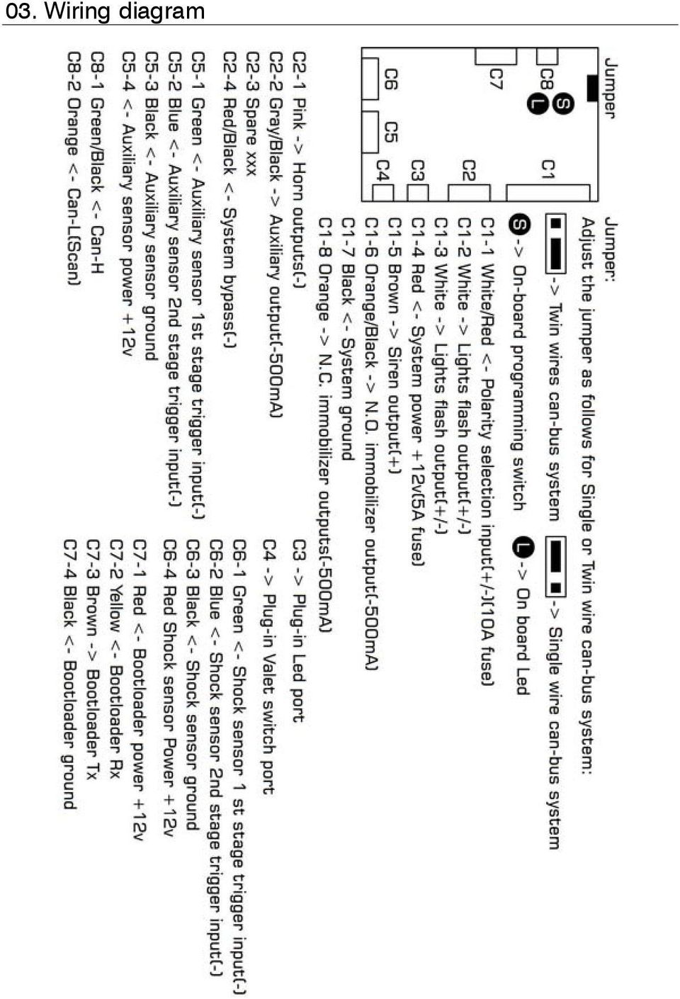
5 C8-1 & 2 Can-H/Can-L(Scan) Connect both wires or Scan wire only depending on the cars can-bus system C1-1 White/Red - Polarity selection for C1-2 & C1-3 Connect C1-1 to [-] or [+] depending on the needs of C1-2 and C1-3 outputs C1-2 & C1-3 White Lights flash output [- or +] Use both of C1-2 and C1-3 only if the car requires separate left and right circuits C1-4 Red - System power source +12V Connect to constant +12v source C1-5 Brown - Additional siren output [+1A] 1. Siren output will be activated when the system is triggered and alarmed. 2. When programming option #1 is set to Siren the siren will chirp once when the system is armed and twice when it is disarmed. C1-6 Orange/Black - N.O. immobiliser output [-500mA] Connect the N.O. immobiliser output as the fig. below. The relay is switched on when the alarm is disarmed (fail secure) C1-7 Black - system ground This wire must be connected to the chassis of the car. Scrape away any paint or dirt from the area to ensure a good connection C1-8 Orange - N.C immobiliser output [-500mA] Connect N.C. immobiliser output as the fig. below. The relay is switched on when the alarm is armed (fail safe)
![Connect to constant +12v source C1-5 Brown - Additional siren output [+1A] 1. Siren output will be activated when the system is triggered and alarmed. 2.](/docs-images/47/20986250/images/page_5.jpg "When programming option #1 is set to Siren the siren will chirp once when the system is armed and twice when it is disarmed. C1-6 Orange/Black - N.O. immobiliser output [-500mA] Connect the N.O. immobiliser output as the fig.")
6 C2-1 Pink - Car horn output [-] 1. Car horn output will be activated when the system is triggered. 2. When programming option #1 is set to Horn the horn will honk once when the system is armed and twice when it is disarmed. 3. When wiring, an additional relay will required as follows: C2-2 Gray/Black - Auxiliary output [-500mA] 1. This arm output will activate after arming the system and could be used for closing the windows or to drive an external device as desired 2. This output will activate for 10/20/30/40 sec. or continuous after arming the system depending on the setting of option #9 3. When setting to continuous, the output will activate until the system is disarmed. C2-3 Spare input [-] Don t connect C2-4 Red/Black - System bypass wire [-] With the system armed, feed this input with negative input to bypass the shock sensor and ignition trigger wire
![When wiring, an additional relay will required as follows: C2-2 Gray/Black - Auxiliary output [-500mA] 1.](/docs-images/47/20986250/images/page_6.jpg "This arm output will activate after arming the system and could be used for closing the windows or to drive an external device as desired 2. This output will activate for 10/20/30/40 sec.")
7 B. System Programming 01. Setting the optional features Follow the steps below to program the optional features: 1. With the system disarmed and ignition off 2. Open the door and turn the ignition on 3. Press the valet switch 3 times within 10 sec. 4. The siren will sound for 2 sec. to confirm the system is in programming mode * Reset all optional features back to the factory default: Within 10 sec. press and hold the valet switch until the siren sounds for 2 sec. Programming example: To set option #4 to 40 sec. 1. Press the valet switch 4 times within 10 sec. and the siren will chip once after each press of the valet switch 2. After 2 sec., the siren will chirp 4 times to confirm that feature #4 is selected for setting 3. Within 10 sec., press the valet switch until the siren chirp 3 times to confirm the feature has changed to 40 sec.(the siren will respond with a different number of chirp for each press of the valet switch) 4. After 2 sec., the siren will sound for 1 sec. to confirm the 40 sec. is programmed 5. Within 10 sec. press the valet switch to select the next feature for programming. If the valet switch is not pressed again within 10 sec. the system will leave the programming mode and the siren will sound for 2 sec. to confirm * The system will leave the programming mode as follows: 1. Turn off the ignition or close the door during the programming mode 2. If the valet switch is not pressed within 10 sec

8 02. Optional feature table Item Features 1 chirp 2 chirp 3 chirp 4 chirp 5 chirp 01 Arm & Disarm Confirmation Disable Flash Horn Siren* Siren+Flash 02 Lights Flashing Output Normal* Pulse Continuous 03 Auto Engine Disable(AED) Disable* Mode-I Mode-II 04 Interior Light Delay Disable 25sec.* 40sec. 60sec. 05 Passive Arming Disable* Mode-I Mode-II 06 Passive Arming Timer 30sec. 180sec.* 07 Auto Rearm Disable* Enable 08 Alarm Duration 30sec.* 60sec. 09 Auxiliary Output 10sec. 20sec.* 30sec. 40sec. Continuous 10 Override Code 1 Flash* 2 ~ 10 Flashes *Factory default = asterisk

9 C. Explanation of Optional Features 01. Arm & disarm confirmation This feature can make the indicator lights flash and/or car horn/siren chirp when pressing the factory remote to arm or disarm the system as follows: 2 chirp = Flash Setting this feature to Flash will make the lights flashing once when arming and twice when disarming 3 chirp = Horn This feature will make the car horn honking once when arming and twice when disarming 4 chirp = Siren This feature will make the siren chirp once when arming and twice when disarming 4 chirp = Siren+Flash This feature will have the siren chirp once and lights flash once when arming and twice when disarming 02. Lights flash output This feature provides different methods to wire the lights flash output as follows: 1 chirp = Normal When wiring the output to Indicators directly as normal then set programming to Normal 2 chirp = Pulse & 3 chirp = Constant If the indicators cannot be wired directly connect the output to the hazard lights as below and then select the appropriate format Pulse or Constant depending on the type of hazard lights

10 After wiring according to the above diagram and setting the format Pulse or Continuous then try to flash the lights by triggering the system. In case the lights won t flash as expected then proceed to the learning mode as follows: 1. Turn on the hazard lights to have the indicators flashing 2. Turn the ignition on and off 3 times (on-off-on-off-on-off) with system disarmed 3. The siren will chirp once to confirm the system is in learning mode 4. With 10 sec. press and hold the valet switch 5. Release the valet switch when the indicators flash 10 times after the LED is on 6. Then the LED turns off and siren chirps once to confirm the learning is done 7. The system will leave the learning mode as follows and the siren confirming with 1 chirp. In this case, the previous setting will remain Turn the ignition on during the learning mode If the valet switch is not pressed within 10 sec. 03. Auto engine disable (AED) This feature offers the car more security by disabling the starter operation is as follows: 2 chirp = Mode-I 1. Turn the ignition off 2. The status LED starts to flash sec. later the AED will be active and the LED turns off to confirm 4. Turning the ignition on or pressing the unlock button of the factory remote within 20 sec. will cancel the countdown and the LED will be off to confirm 5. To start the countdown again, simply turn the ignition on then

11 off and the LED will flash to confirm 6. Press the remote to arm the system during the 20 sec. countdown to activate the AED immediately *To deactivate the AED: When disarming the system, the AED will remain on and the only way to deactivate the AED is to operate the override 3 chirp = Mode-II 1. Turn the ignition off 2. The status LED starts to flash sec. later the AED will be on and LED turns off to confirm 4. Turning the ignition on or pressing the unlock button of factory remote within the 30 sec. will cancel the countdown and the LED will be off to confirm 5. To start the countdown again simply turn the ignition on then off and the LED will flash to confirm 6. Press the remote to arm the system during the 30 sec. countdown to activate the AED immediately *To deactivate the AED: There are 2 way to deactivate the AED in mode-ii as follows: 1. Press the unlock button to disarm the system, the AED will be deactivated at the same time 2. By override * When AED is activated, the system can t enter the following modes: Code learning Programming of the optional features Hazard lights learning Valet mode * The differences between Mode-I and Mode-II: In Mode-I, the system will enter AED mode 20 sec. after turning the ignition off In Mode-II, the system will entry AED mode 30 sec. after turning the ignition off In Mode-I, the AED won t be deactivated after disarming the system by pressing the unlock button of factory remote and

12 can only be deactivated by using the override In Mode-II, the AED will be deactivated when disarming the system by pressing the unlock button of the factory remote. Operating the override will also deactivate the AED 04. Interior light delay 1 chirp = Disable The Siren/Horn and flashing outputs will activate an additional 3 times when arming the system if any of the doors, boot or bonnet is not closed properly and the open area will be bypassed until closed 2, 3, 4 chirp = 25, 40, 60 sec. 1. The Siren/Horn and flashing outputs will activate an additional 3 times when arming the system if the boot or bonnet is not closed properly and then the open area will be bypassed until closed 2. The Siren/Horn and flashing outputs will activate an additional 3 times after 25, 40 or 60 sec. of arming the system if a door is not closed properly. The doors will be bypassed until closed. 05. Passive arming When enabled, the system will arm as follows: 2 chirp = Mode-I The operation is as follows: 1. Turn the ignition off 2. Close the doors, boot and bonnet properly 3. LED starts to flash fast and the system will arm in 30 or 180 sec. 4. The Auxiliary Output will activate as per the setting of feature #9 * Opening the door, boot or bonnet will interrupt the countdown until closed again 3 chirp = Mode-II The operation of Mode-II is exactly same as Mode-I but the Auxiliary Output won t activate

13 06. Passive arming timer 1 chirp = 30 sec. The system will enter arm mode 30 sec. after closing the last opened door, boot or bonnet with ignition off 2 chirp = 180 sec. The system will enter arm mode 180 sec. after closing the last opened door, boot or bonnet with ignition off 07. Auto rearm 2 chirp = Enable When enabled, the system will arm itself again 30 sec. after disarming if none of the doors, boot or bonnet are opened 08. Alarm duration 1 chirp = 30 sec. The siren/horn will sound for 30 sec. each cycle when the system is triggered 2 chirp = 60 sec. The siren/ horn will sound for 60 sec. each cycle when the system is triggered 09. Auxiliary output The output will activate when arming the system as follows: 1, 2, 3, 4 chirp = 10, 20, 30, 40 sec. When set to 10/20/30/40 sec. the output will activate for 10, 20, 30 or 40 sec. after the system is armed 5 chirp = Continuous When set to Continuous the output will activate when the system is armed until the system is disarmed 10. Override code Follow the steps below to program the override code: (For example: Programming 4 as the new override code) 1. Enter the programming mode 2. Within 10 sec. press the valet switch 10 times to select feature #10, the siren will chip once for each press of the valet switch

14 3. After 2 sec., the siren will chirp 10 times to confirm the feature #10 is selected for programming 4. Within 2 sec., press the valet switch once, the siren will chirp 2 times to indicate the current code is 2 (if the default code is 1) 5. Within 2 sec.press the valet switch once, the siren will chirp 3 times to indicate the current code is 3 6. Within 2 sec.press the valet switch once. the siren will chirp 4 times to indicate the current code is 4 7. Then 2 sec. later the siren will sound for 1 sec. to confirm the code has been changed to 4 8. Within 10 sec. press the valet switch to select next feature for programming or the system will leave the programming mode and the siren will sound for 2 sec. to confirm * The system will leave the programming mode as follows: 1. Turn the ignition off or close the door during programming 2. If the valet switch is not pressed within 2 sec or 10 sec.

SNIPER X1 VEHICLE SECURITY SYSTEM
 SNIPER X1 VEHICLE SECURITY SYSTEM Installation Manual Table of Contents 1. FEATURES & SPECIFICATIONS... 2 2. TRANSMITTER BUTTONS:... 2 3. FUNCTION... 2 3.1 Key Function:...2 3.2 Remote Transmitter Code
How To Set Off An Alarm On A Car With A Car Alarm On It
 AUTO SECURITY SYSTEM USER S OPERATION GUIDE FCC ID NOTICE This device complies with Part 15 of the FCC rules. Operation is subject to the following conditions: 1. This device may not cause harmful interference,
1R / 4-BUTTON SERIES
 Button 1 1R / 4-BUTTON SERIES VEHICLE SECURITY SYSTEM Standard Features: Two 4-Button Remote Transmitters Status indicator (LED) Valet / override switch Multi-tone siren Dual stage impact detector Remote
INSTALLATION GUIDE. www.security.soundstream.com FCC ID NOTICE
 AL.1 AUTO SECURITY SYSTEM INSTALLATION GUIDE www.security.soundstream.com FCC ID NOTICE This device complies with Part 15 of the FCC rules. Operation is subject to the following conditions: 1. This device
WIRING HARNESS FOR AS635P4. BLUE PLUG RED, BLUE, BLACK, WHITE - Plug in dual stage sensor harness
 WIRING HARNESS FOR AS635P4 ANTENNA NOT USED 5 PIN WHITE PLUG 2 PIN WHITE PLUG GREEN - PARKING BRAKE INPUT (-) BLUE - NOT USED 3 PIN BLUE PLUG RED, BLUE, BLACK, WHITE - Plug in dual stage sensor harness
VEHICLE SECURITY SYSTEM G25/G20
 VEHICLE SECURITY SYSTEM G25/G20 Limited Lifetime Warranty This vehicle security system is warranted to the original purchaser, to be free from defects in material and workmanship. The manufacturer will
How To Control A Car Alarm On A Car With A Remote Control System
 MODEL CA100 REMOTE CONTROL AUTO ALARM SYSTEM INSTALLATION & OPERATION INSTRUCTIONS WIRING DIAGRAM Black Antenna Wire 6 Pin 6 Pin Mini Connector Valet Switch Blue LED Indicator Blue Wire: (-) 200mA Unlock
PRO PLM Installation Instructions
 PRO PLM Installation Instructions PROFESSIONAL INSTALLATION STRONGLY RECOMMENDED Installation Precautions: Roll down window to avoid locking keys in vehicle during installation Avoid mounting components
Button 1 Button 2. Button 3 Button 4. Programmed Remote Transmitter. Button Function Condition
 WWW.STELLAR.COM ST9000 SECURITY SYSTEM Button Function Condition 1 a. Arm and lock doors b. Car finder with sound c. Temporary stop alarm from sounding d. Remote lock doors 1 for 2 sec. Panic Anytime a.
INSTALLATION MANUAL 3RP / 5RP 4-BUTTON SERIES VEHICLE SECURITY SYSTEMS
 3RP / 5RP 4-BUTTON SERIES VEHICLE SECURITY SYSTEMS INSTALLATION MANUAL Before you begin the installation Read the INSTRUCTIONS! Always use a multi-meter when verifying vehicle wiring. Before mounting the
e-ask electronic Access Security Keyless-entry
 e-ask electronic Access Security Keyless-entry e-fob Keyless-entry entry System Full-Function Function Installation Manual FCC ID: TV2EFOB1 (UM20 ~ 22793-02) Table of Contents Introduction... 1 e-fob Operation
REMOTE TRANSMITTER LAYOUT
 Full Featured Keyless Entry System with Optional Starter Defeat and Passive Immobilize Feature SYSTEM MANUA STANDARD FEATURES Some of the system s standard features include: Two 4-button remote transmitters
SP-100 REMOTE CONTROL ALARM SYSTEM INSTALLATION & OPERATING INSTRUCTIONS INTRODUCTION
 SP-100 REMOTE CONTROL ALARM SYSTEM INSTALLATION & OPERATING INSTRUCTIONS INTRODUCTION CONGRATULATIONS on your choice of a Security Plus Remote Alarm System by Crimestopper Security Products Inc. This booklet
REMOTE START SECURITY SYSTEM OWNERS MANUAL
 REMOTE START SECURITY SYSTEM OWNERS MANUAL Standard Features The System has the following standard features: 5-button remote transmitter Status indicator (LED) Valet/Service mode switch Remote Start capabilities
INSTRUCTION MANUAL FOR. Remote Control Car Alarm with Impact Sensor, Mini-Battery Backup Siren & Engine Immobiliser
 INSTRUCTION MANUAL FOR Remote Control Car Alarm with Impact Sensor, Mini-Battery Backup Siren & Engine Immobiliser A.C.N 001 621 610 SYDNEY / AUSTRALIA Build Date: TO ARM/DISARM ALARM The alarm is activated
Security and Remote Start Installation Guide for models: CA 6150 CA 6550
 PROFESSIONAL SERIES Security and Remote Start Installation Guide for models: CA 6150 CA 6550 2009 Audiovox Electronics Corporation. All rights reserved. 1 Table of Contents Before You Begin... 4 Wire Connection
Car Alarm Series 2 B 2 Buttons
 Car Alarm Series 2 B 2 Buttons G22 SE (External - Shock Sensor) Version 3 Software 67 Plus www.geniuscaralarm.com 21 CAR ALARM GENIUS Series 2B 2 Buttons - G22 Se (External Shock Sensor) Module controlled
UPGRADE ALARM USER INSTRUCTIONS
 UPGRADE ALARM USER INSTRUCTIONS CYCL PS SECURITY SYSTEMS PROUDLY AUSTRALIAN Proudly designed and engineered in Australia by Dynamco Pty Ltd. Your emergency override PIN is Keep this number in a safe place
ODYSSEY. Security System Owner s Manual. Kit No. 08E51-SHJ-100 08E55-SHJ-100. 2004 American Honda Motor Co., Inc. - All Rights Reserved.
 Kit No. 08E5-SHJ-00 08E55-SHJ-00 Security System Owner s Manual ODYSSEY 004 American Honda Motor Co., Inc. - All Rights Reserved. Contents Introduction... 3 Emergency Disarming During the Panic Alarm Activation...
OWNER S OPERATION GUIDE English
 OWNER S OPERATION GUIDE English 76E268-0030-0606S -1- Printed in Japan Important WARNING / CAUTION / NOTE Please read this manual and follow its instructions carefully. To emphasize special information,
OPERATING INSTRUCTIONS SECURITY SYSTEM KIT NO.: 08E51-EP4-101. 2004 American Honda Motor Co., Inc. - All Rights Reserved. 1
 OPERATING INSTRUCTIONS SECURITY SYSTEM KIT NO.: 8E5-EP4-24 American Honda Motor Co., Inc. - All Rights Reserved. Contents Introduction... 3 Emergency Disarming During Alarming... 4 During the Entry Delay
VEHICLE SECURITY SYSTEM Optional Remote Start Module and 2-way Transmitter Instructions Included
 VEHICLE SECURITY SYSTEM Optional Remote Start Module and 2-way Transmitter Instructions Included STANDARD FEATURES Some of the system s standard features include: 4-button remote transmitter LED Status
AVS A4 alarm Owner s manual
 AVS A4 alarm Owner s manual Thank you for choosing an AVS A4 car security system. It has been designed to provide a superior level of security for you and your vehicle. Please read this guide carefully
VEHICLE SECURITY SYSTEM. Car Alarm System With Command Confirmation
 VEHICLE SECURITY SYSTEM Car Alarm System With Command Confirmation About Your System Congratulations on your purchase of this state-of-the-art vehicle security system. With proper installation this system
Model AM2. Installation Guide
 Model AM2 Installation Guide NOTE: This product is intended for installation by a professional installer only! Any attempt to install this product by any person other than a trained professional may result
VEHICLE SECURITY SYSTEM Optional Remote Start Module and 2-way Transmitter Instructions Included
 VEHICLE SECURITY SYSTEM Optional Remote Start Module and 2-way Transmitter Instructions Included STANDARD FEATURES Some of the system s standard features include: 4-button remote transmitter LED Status
MAGICAR M871A. Car alarm with two-way remote User s guide
 MAGICAR M871A Car alarm with two-way remote User s guide EN MAGICAR M871A Car alarm with two-way remote User s guide TABLE OF CONTENTS Table of contents...2 1. Important notice...4 2. Introduction...4
Installation Guide Security and Remote Start
 Installation Guide Security and Remote Start This product is intended for installation by a professional installer only! Attempts to install this product by a person other than a trained professional may
TOMAHAWK CAR ALARMS. TW-9010 Two Way Car Alarm System
 TOMAHAWK TW-9010 TOMAHAWK CAR ALARMS TW-9010 Two Way Car Alarm System USER MANUAL INSTRUCTIONS FOR INSTALLATION TOMAHAWK TW-9010 1 2 3 4 5 6 7 8 9 10 11 12 13 14 15 16 17 18 19 20 21 22 23 24 25 26 27
VEHICLE SECURITY SYSTEM OPERATOR'S INSTRUCTIONS
 :). VEHICLE SECURITY SYSTEM OPERATOR'S INSTRUCTIONS (8 I NS070S Rev. A 12195 ThIs product is protected by U.S. patent number 5,049,867. @ Code Alarm, Inc. 1994 All rights reserved. Printed in the USA.
INSTALLATION MANUAL VEHICLE SECURITY SYSTEM CE-SS200
 INSTALLATION MANUAL VEHICLE SECURITY SYSTEM CE-SS200 FUSION CULTURE TABLE OF CONTENTS There s no point doing something if no one notices. We ve always believed the way to make things happen is by getting
Multi Function, User Configurable Remote Vehicle Security System with 4 Button Replaceable Membrane Remote Transmitter
 MODEL PRO-9744 INSTALLATION MANUAL Multi Function, User Configurable Remote Vehicle Security System with 4 Button Replaceable Membrane Remote Transmitter This System Allows The Transmitter Buttons To Be
2004 Directed Electronics, Inc. Vista, CA N426V 07-04
 350HV Installation Guide NOTE: This product is intended for installation by a professional installer only! Any attempt to install this product by any person other than a trained professional may result
MAGICAR M870AS. Car alarm with two-way remote and remote - start system Installation guide
 MAGICAR M870AS Car alarm with two-way remote and remote - start system Installation guide EN English TABLE OF CONTENTS I. INTRODUCTION...4 II. PLACING...4 III. ADDITIONAL RELAY 12V CONNECTION...1 IV. WIRING
535T Window Automation System
 535T Window Automation System Installation Guide NOTE: This product is intended for installation by a professional installer only! Any attempt to install this product by any person other than a trained
Entering Program Mode for Vehicle Security and Remote Start Systems
 Entering Program Mode for Vehicle Security and Remote Start Systems System 100 Keyless Entry Remote Start System (1 Way and 2-Way Remote Start Systems) Kit Part # s: 7L2Z-19G364-AA AL2Z-19G364-A 9G1Z-19G364-A
ASTRA 4000RS/1000RS-DBP G55 SERIES VEHICLE SECURITY SYSTEM WITH REMOTE START PRODUCT MANUAL
 ASTRA 4000RS/1000RS-DBP G55 SERIES VEHICLE SECURITY SYSTEM WITH REMOTE START PRODUCT MANUAL Limited Lifetime Warranty This vehicle security system is warranted to the original purchaser, to be free from
INSTALLATION GUIDE OWNER S GUIDE
 INSTALLATION GUIDE OWNER S GUIDE SECURITY SYSTEM PRO-SERIES 5002 CONTENTS System Features... 1-2 System Components... 2 Technical Assistance... 2 Before You Begin... 2 Precautions... 2-3 Making Connections...
INSTALLATION GUIDE OWNER S GUIDE
 INSTALLATION GUIDE OWNER S GUIDE TALKING ALARM MODEL 3001 CONTENTS System Features... 1 Technical Assistance... 1 Wiring Instructions... 2 Installation Instructions... 3 Operating Instructions... 4-5 Technical
e-ask electronic Access Security Keyless-entry Consumer Manual FCC ID: TV2EFOB1 (UM12 ~ 22271-02)
") e-ask electronic Access Security Keyless-entry e-fob / e-pade Consumer Manual FCC ID: TV2EFOB1 (UM12 ~ 22271-02) Table of Contents Introduction... 1 e-fob Operation and Features - Standard... 2 e-fob Operation
e-ask electronic Access Security Keyless-entry e-fob / e-pade Consumer Manual FCC ID: TV2EFOB1 (UM12 ~ 22271-02) Table of Contents Introduction... 1 e-fob Operation and Features - Standard... 2 e-fob Operation
About Your System NOTE: What is included: Options and Accessories:
 2-WAY CAR ALARM SYSTEM WITH REMOTE ENGINE START E8 MODEL IMPORTANT: Please read the entire manual for complete details on the features, accessories and operation before attempting to use your security
NO ONE DARES COME CLOSE
 The company behind Viper Auto Security Systems is Directed. Since its inception, Directed has had one purpose, to provide consumers with the finest vehicle security and accessories available. The recipient
Model 5303 Installation Guide
 Model 5303 Installation Guide This product is intended for installation by a professional installer only! Attempts to install this product by a person other than a trained professional may result in severe
Vehicle Security System VSS3 - Alarm system remote. System Setting Guide - English
 Vehicle Security System VSS3 - Alarm system remote System Setting Guide - English Dear Customer, In this guide you will find the information and operations necessary in order to activate and deactivate
CA-125 Owner's Manual
 Remote Vehicle Control System CA-125 Owner's Manual Vehicle Security System With Remote Keyless Entry IMPORTANT NOTE: The operation of the Security and Convenience System as described in this manual is
Vehicle Alarm System With Channel 2 Auxiliary Output Installation Instructions
 Model PRO 9842 Installation Manual Vehicle Alarm System With Channel 2 Auxiliary Output Installation Instructions This Unit Is Intended For Installation In Vehicles With 12 Volt Negative Ground Electrical
RF-350 PROFESSIONAL VEHICLE SECURITY SYSTEM WITH KEYLESS ENTRY. INSTALLATION & USERS MANUAL (For Authorized Dealers Only)
") RF-350 PROFESSIONAL VEHICLE SECURITY SYSTEM WITH KEYLESS ENTRY INSTALLATION & USERS MANUAL (For Authorized Dealers Only) Please register your product at www.autopageusa.com THIS PRODUCT IS DESIGNED FOR
RF-350 PROFESSIONAL VEHICLE SECURITY SYSTEM WITH KEYLESS ENTRY INSTALLATION & USERS MANUAL (For Authorized Dealers Only) Please register your product at www.autopageusa.com THIS PRODUCT IS DESIGNED FOR
What you get Welcome to the best generation of security with remote start. Your system contains everything you need.
 Congratulations Congratulations on the purchase of your state-of-the-art security and remote start system. Reading this Owner s Guide prior to using your system will help maximize the use of your system
PUSH BUTTON START INSTALLATION MANUAL
 PUSH BUTTON START INSTALLATION MANUAL ALTHOUGH THIS PRODUCT HAS BEEN THOROUGHLY TESTED KPIERSON TECHNOLOGIES ASSUMES NO RESPONSIBILITY FOR ANY DAMAGE THAT MAY RESULT BY THE INSTALLATION OF THIS PRODUCT.
Installation Manual, DEFA Auto Security Car Alarm 800 Series
 Installation Manual, DEFA Auto Security Car Alarm 800 Series 8028 (D11) 1 DEFA Auto Security 800 Series Glassbreake Sensor Microwave Sensor Backup Alarm Immobilizer Module 8028 (D10) 2 Wiring diagram 14
PATENTED: www.voxxintl.com/company/patents
 Model APS-997C Installation Manual 2 Way LCD Vehicle Security and Table Of Contents: Remote Start System Before You Begin Page 2 Wire Harnesses Quick View Page 3 and 4 Installation Of The Major Components
AM1 Security System installation guide
 AM1 Security System installation guide 2005 Directed Electronics, Inc. Vista, CA N427A 01-05 NOTE: This product is intended for installation by a professional installer only! Any attempt to install this
RS-1301DP/1303DP/1304DP 1-WAY SYSTEM RS-1300DP ADD-ON MODULE DP SERIES (Data Port)
") RS-1301DP/1303DP/1304DP 1-WAY SYSTEM RS-1300DP ADD-ON MODULE DP SERIES (Data Port) OPERATING INSTRUCTIONS **IMPORTANT NOTES:- FOR RS-1300DP MODEL ONLY** RS-1300DP Model is an add-on/expansion unit, without
RS-1301DP/1303DP/1304DP 1-WAY SYSTEM RS-1300DP ADD-ON MODULE DP SERIES (Data Port) OPERATING INSTRUCTIONS **IMPORTANT NOTES:- FOR RS-1300DP MODEL ONLY** RS-1300DP Model is an add-on/expansion unit, without
CM6000 Install Guide. Table of Contents
 Version 6.07 Table of Contents CM6000 Introduction 4 Kit Contents 4 Installation Basics 5 Remote Programming Routine 6 Placement and Use of Components 6 Common Procedures 11 Wiring Descriptions 15 Option
AL-1650-EDPB AL-1750-EDPB AL-1850-EDPB AL-1950-EDPB AL-2050-EDPB
 AL-1650-EDPB AL-1750-EDPB AL-1850-EDPB AL-1950-EDPB AL-2050-EDPB Deluxe Security & Remote Start System Installation Guide July 11, 2012 Temporary cover. Color cover is in a separate file. Installation
PATENTED: www.voxxintl.com/company/patents
 Model PRO9776C Installation Manual Vehicle Security System Table Of Contents: with Remote Start Before You Begin Page 2 Wire Harnesses Quick View Page 3-4 Installation of the Major Components Page 5 Wiring
Owner s Guide. ca6554
 PROFESSIONAL SERIES Owner s Guide For Models: ca6554 Deluxe Vehicle Security and Remote Start System with 2 Way Confirming LCD Remote Control IMPORTANT NOTE: The operation of the Security and Convenience
CA 1050 Owner s Guide
 PROFESSIONAL SERIES CA 1050 Owner s Guide Vehicle Security and Keyless Entry System IMPORTANT NOTE: The operation of the Security and Convenience System as described in this manual is applicable to most
4600 CAN/PLIP INSTALLATION MANUAL
 4600 CAN/PLIP INSTALLATION MANUAL Summary 1. KIT CONTENTS...3 2. INTRODUCTION & INSTALLATION METHODOLOGY (how to access to the vehicle specific technical documents, Data Linker tool, Antares software,
GALAXY 5000RS/2000RS SERIES-DBP
 GALAXY 5000RS/2000RS SERIES-DBP DATA BUS PORT VEHICLE SECURITY SYSTEM WITH REMOTE START PRODUCT MANUAL Limited Lifetime Warranty This vehicle security system is warranted to the original purchaser, to
RS1-G4 / RS3-G4 / RS4-G4 RS7-G4 (PAGING SYSTEM) RS00-G4 (ADD-ON MODULE)
 RS00-G4 (ADD-ON MODULE)") RS1-G4 / RS3-G4 / RS4-G4 RS7-G4 (PAGING SYSTEM) RS00-G4 (ADD-ON MODULE) REMOTE START SYSTEM INSTALLATION INSTRUCTIONS CONGRATULATIONS on your choice of a Cool Start System with Data Port Technology for
RS1-G4 / RS3-G4 / RS4-G4 RS7-G4 (PAGING SYSTEM) RS00-G4 (ADD-ON MODULE) REMOTE START SYSTEM INSTALLATION INSTRUCTIONS CONGRATULATIONS on your choice of a Cool Start System with Data Port Technology for
SECURITY SYSTEM OWNER S MANUAL MIATA, MAZDASPEED MX-5
 SECURITY SYSTEM OWNER S MANUAL MIATA, MAZDASPEED MX-5 Introduction l l l l l l l l l l l l l l l l Thank you for purchasing the Mazda Security Upgrade package. This system is designed to enhance the security
MotorCycle Alarm by DEF COM 3 INSTALLATION MANUAL 80 C
 DEF COM 3 INSTALLATI MANUAL MotorCycle Alarm by IMMOBILISER (FAIL SAFE SYSTEM) Positive Logic (the relay switches over when the central unit is disarmed and ignition +15 is present.) Fig.2 Fig.3 SUPPLEMTARY
LAND ROVER MANUAL CONTENTS APPLICATIONS GENERAL OPERATION SPECIAL FUNCTIONS REMOTE CONTROL PROGRAMMING
 LAND ROVER LAND ROVER MANUAL CONTENTS APPLICATIONS GENERAL OPERATION SPECIAL FUNCTIONS REMOTE CONTROL PROGRAMMING APPLICATIONS VEHICLE SYSTEM YEAR CABLE CLASSIC RANGE ROVER 10AS 95 ON ADC110-B DEFENDER
EZ-90 / EZ-91 REMOTE ENGINE STARTING SYSTEM OPERATING INSTRUCTIONS INTRODUCTION REV A - 08.2004
 EZ-90 / EZ-91 REMOTE ENGINE STARTING SYSTEM OPERATING INSTRUCTIONS INTRODUCTION **IMPORTANT NOTES:- FOR EZ-91 MODEL ONLY** The EZ-91 model is an add-on (expansion unit), without remotes or antenna. It
i ChatterBox! Motorcycle Security
 i Before you Start the Installation * Please read this manual to become familiar with the requirements necessary to complete the installation. * Use a high quality multi-meter to test all wires before
0 Copyright 1997 Subaru of America, Inc.
 0 Copyright 1997 Subaru of America, Inc. All rights reserved. This book may not be reproduced in whole or in part without the express written permission of Subaru of America, Inc. Subaru of America, Inc.
288-289 29024V COMPACT ALARM SYSTEMS
 288-289 29024V COMPACT ALARM SYSTEMS The system is manufactured from the highest quality components to ensure a long trouble free operating life. These instructions are intended to familiarise you with
DC-8706K Auto Dial Alarm System
 DC-8706K Auto Dial Alarm System User Guide Basic Contents: 1x the host unit; 1x wireless door (window) magnet; 1x wireless infrared detector; 2x remote control; 1x siren; 1x phone core; 1x AC to DC power
FUNCTIONS FUNCTIONS PROGRAMMABLE THROUGH THE TRANSMITTER DESCRIPTION
 DESCRIPTION The systems 7463 and 7462 are modular systems which consists of an alarm unit and one audible external siren. These alarm systems can be installed on vehicles with 12V battery with negative
4600 CAN/PLIP INSTALLATION MANUAL
 4600 CAN/PLIP INSTALLATION MANUAL Summary 1.KIT CONTENTS...3 2. INTRODUCTION & INSTALLATION METHODOLOGY (how to access to the vehicle specifi c technical documents, Data Linker tool, Antares software,
Copyright 2002-2004 Triple S Customs
 CHEVROLET SILVERADO 1988-2005 VEHICLE WIRING Copyright 2002-2004 Triple S Customs WIRING INFORMATION: 1988 Chevy Silverado Full-Size 2- POWER DOOR LOCK (5-wire reverse polarity) POWER DOOR UNLOCK (5-wire
Owner s Guide for the 220 MAX models (Rev D) Recreationnal Vehicle Security System
 Recreationnal Vehicle Security System") Owner s Guide for the 220 MAX models (Rev D) Recreationnal Vehicle Security System [Table of contents] Your Warranty... 1 What s included... 2 System maintenance... 2 Transmitter Functions... 3 Arming
Owner s Guide for the 220 MAX models (Rev D) Recreationnal Vehicle Security System [Table of contents] Your Warranty... 1 What s included... 2 System maintenance... 2 Transmitter Functions... 3 Arming
AM9. Owner's Guide. 2010 Directed Electronics. G5303 2010-07
 AM9 Owner's Guide 2010 Directed Electronics. G5303 2010-07 Congratulations Congratulations on the purchase of your state-of-the-art security/keyless entry and remote start system. Reading this Owner s
www.dsecanada.com istart Security and Remote Start Installation Guide ISO 9001 Fabriqué sous norme
 D S E www.dsecanada.com istart Security and Remote Start Installation Guide Fabriqué sous norme ISO 9001 Certified Manufacturer This product is intended for installation by a professional installer only!
HONDA ACCORD 1985-2005
 HONDA ACCORD 1985-2005 VEHICLE WIRING Copyright 2002-2004 Triple S Customs WIRING INFORMATION: 1985 Honda Accord WIRE WIRE COLOR WIRE LOCATION 12V CONSTANT WHITE or WHITE/BLACK Ignition Harness STARTER
USER MANUAL. For all gas- diesel-powered or hybrid vehicles (FRANÇAIS AU VERSO) CONSULT SAFETY PRECAUTION SECTION SOME FEATURES MAY REQUIRE
 CONSULT SAFETY PRECAUTION SECTION SOME FEATURES MAY REQUIRE") USER MANUAL REMOTE CONTROL ENGINE STARTER Model RS-623 Model RS-721 For all gas- diesel-powered or hybrid vehicles (FRANÇAIS AU VERSO) CONSULT SAFETY PRECAUTION SECTION BEFORE USING THIS PRODUCT. SOME
USER MANUAL REMOTE CONTROL ENGINE STARTER Model RS-623 Model RS-721 For all gas- diesel-powered or hybrid vehicles (FRANÇAIS AU VERSO) CONSULT SAFETY PRECAUTION SECTION BEFORE USING THIS PRODUCT. SOME
Security System. User Guide for the LED Command Center
 Security System User Guide for the LED Command Center MY SECURITY COMPANY IS: CALL BEFORE TEST: THIS SECURITY SYSTEM IS CONNECTED TO TELEPHONE NUMBER: THE SECURITY CONTROL PANEL IS CONNECTED TO THE PHONE
Two-Way Remote User s Guide. Thank you.
 Thank you. Thank you for your purchase of an MAGICAR alarm and/or remote-start system. MAGICAR alarms and remote-start systems are the most advanced systems on the market with amazing features, incomparable
SECURITY SYSTEM ADP-CAN
 INSTALLATION INSTRUCTION SECURITY SYSTEM ADP-CAN Introduction Motorcar security system ADP-CAN is for motorcars provided with CAN net. It is for the work with the motorcar factory security systems or remote
2004 directed electronics, inc.
 Model 564T Owner s Guide Hornet limited lifetime consumer warranty For a period of one calendar year from the date of purchase of this auto-security device, Directed Electronics, Inc. promises to the ORIGINAL
TX GSM SMS Auto-dial Alarm System. Installation and User Manual
 TX GSM SMS Auto-dial Alarm System Installation and User Manual Product Features: 1. 16 wireless zones, 3 wired zones alarm system, suitable for small to medium size offices and homes. 2. The system uses
cod.: ISUT290I2-UK FILENAME:ISUT290I2-UK.P65 290i2/291 INSURANCE APPROVED ALARM/IMMOBILISER USER GUIDE CAR ALARM SYSTEMS
 cod.: ISUT290I2-UK FILENAME:ISUT290I2-UK.P65 GB 290i2/291 INSURANCE APPROVED ALARM/IMMOBILISER USER GUIDE CAR ALARM SYSTEMS These systems are manufactured from the highest quality components to ensure
FanControl U2 Connection of the module in BMW and Mini Cooper vehicles
 FanControl U2 Connection of the module in BMW and Mini Cooper vehicles www.tecel.ru Module application in BMW 5 (F10), BMW 6 (F13), BMW 7 (F01, F02) vehicles Group 4, subgroup 2 CАN L green CAN H orange
Fitting/Installation Guide - UNIVERSAL
 ATTENTION: This wiring information is being provided free of charge and on an as is basis, without any representation or warranty. It is your responsibility to verify any circuit before interfacing with
KEYLESS ENTRY UPGRADE SECURITY SYSTEM for 2004 TOYOTA HIGHLANDER
 KEYLESS ENTRY UPGRADE SECURITY SYSTEM for 2004 TOYOTA HIGHLANDER DEALER SERVICE AND INSTALLATION MANUAL KIT NO. 00016-30915 Contents PARTS LIST... 2 PARTS ILLUSTRATIONS... 2 VEHICLE PREPARATION... 3 INSTALLING
Using your LED Plus keypad
 Using your LED Plus keypad System 238 System 2316 System 238i System 2316i Part Number 5-051-372-00 Rev B Thank you for purchasing this C&K alarm system Your system is one of the most powerful and advanced
User s Information Guide R1A
 HSC505-R Home Security Controller - User Manual Release R1a Pi HSC505 and Pi HSC505R Home Security Controller User s Information Guide R1A Page 1 QD Dynamics (Pty) Ltd reserves the right to make changes
NELSON VOLTAGE MONITOR INSTALLATION & PROGRAMMING MANUAL
 NELSON VOLTAGE MONITOR INSTALLATION & PROGRAMMING MANUAL CONTENTS GENERAL INFORMATION...3 INSTALLATION...3 FIELD WIRING...4 PROGRAMMING...4 Circuit Monitor Options...5 Power Frequency...5 Alarm Silence
RS900ER / RS901 SERIES III OPERATING INSTRUCTIONS
 RS900ER / RS901 SERIES III OPERATING INSTRUCTIONS CONGRATULATIONS on your choice of a CoolStart Remote Engine Starter by Crimestopper Security Products Inc. This booklet contains the information necessary
MODEL RSS-2524 USER MANUAL REMOTE CONTROL ENGINE STARTER. For all hybrid, gasand diesel-powered vehicles. (FRANÇAIS AU VERSO)
") REMOTE CONTROL ENGINE STARTER USER MANUAL MODEL RSS-2524 For all hybrid, gasand diesel-powered vehicles. This model may be equipped with an optional security system. (FRANÇAIS AU VERSO) CONSULT SAFETY
REMOTE CONTROL ENGINE STARTER USER MANUAL MODEL RSS-2524 For all hybrid, gasand diesel-powered vehicles. This model may be equipped with an optional security system. (FRANÇAIS AU VERSO) CONSULT SAFETY
VEHICLE TRACKING SYSTEM SKYTRAK-3000
 VEHICLE TRACKING SYSTEM SKYTRAK-3000 Limited Lifetime Warranty This vehicle tracking system is warranted to the original purchaser, to be free from defects in material and workmanship. The manufacturer
4693-4698 USER MANUAL
 4693-4698 USER MANUAL Summary 1. INTRODUCTION... 4 2. ARMING AND DISARMING THE SYSTEM...4 3. ACTIVE FUNCTIONS (functions description)...5 4. FUNCTIONS PROGRAMMABLE BY A COBRA INSTALLER (functions description)...7
Quick Installation Guide LCD GSM ALARM SYSTEM LH http://www.usmartbuy.com
 A. Manipulation Specification Quick Installation Guide 1. Arming Arming means all-around guarded when there is no person at home. All detectors are working. Once something triggers any of the detectors,
2005 directed electronics all rights reserved
 Model 560XV Owner s Guide limited lifetime consumer warranty Directed Electronics ("Directed") promises to the original purchaser to repair or replace with a comparable reconditioned model any Directed
G-100/200 Operation & Installation
 G-100/200 Operation & Installation 2 Contents 7 Installation 15 Getting Started 16 GPS Mode Setup 18 Wheel Sensor Mode Setup 20 Fuel Calibration 23 Basic Operation 24 Telemetery Screen 27 Entering a Distance
NO ONE DARES COME CLOSE
 The company behind Viper Auto Security Systems is Directed. Since its inception, Directed has had one purpose, to provide consumers with the finest vehicle security and accessories available. The recipient
Model RSS-2514XR USER MANUAL REMOTE CONTROL ENGINE STARTER. For all gas- and diesel-powered vehicles (FRANÇAIS AU VERSO)
") REMOTE CONTROL ENGINE STARTER USER MANUAL Model RSS-2514XR For all gas- and diesel-powered vehicles This model may be equipped with an optional security system.. (FRANÇAIS AU VERSO) CONSULT SAFETY PRECAUTION
REMOTE CONTROL ENGINE STARTER USER MANUAL Model RSS-2514XR For all gas- and diesel-powered vehicles This model may be equipped with an optional security system.. (FRANÇAIS AU VERSO) CONSULT SAFETY PRECAUTION
The Child Reminder System Installation Manual
 The Child Reminder System Installation Manual Revised June, 2006 Detailed installation information can be found at www.childreminder.com. Get through your installation quickly and easily by calling 1-888-330-6786
Keyless Entry System With Two Auxiliary Outputs Installation Instructions
 Model APS-45B Installation Manual Keyless Entry System With Two Auxiliary Outputs Installation Instructions This Unit Is Intended F Installation In Vehicles With 12 Volt Negative Ground Electrical Systems