What is a multimeter?
|
|
|
- Elijah Rogers
- 10 years ago
- Views:
Transcription
1

2 What is a multimeter? A multimeter is a devise used to measure voltage, resistance and current in electronics & electrical equipment It is also used to test continuity between to 2 points to verify if there is any breaks in circuit or line There are two types of multimeter Analog & Digital Analog has a needle style gauge Digital has a LCD display (Referenced during this PPT)

3 There are 2 styles of multimeters Switched Manually switch between ranges to get most accurate reading. Auto Range Switches between ranges automatically for best reading. Both of these styles work the same

4 Meter leads Red meter lead Is connected to Voltage/Resistance or amperage port Is considered the positive connection Probes Are the handles used to hold tip on the tested connection Tips Are at the end of the probe and provides a connection point Black meter lead Is always connected to the common port Is considered the negative connection

5 Display & Dial Settings Digital Display Shows measured value. Meter Dial Turn dial to change functions. Turn dial to OFF position after use. Panel Indicator Shows each function and setting range to turn dial to. Probe Connections Specific for each function.

6 Common DMM Symbols ~ AC Voltage Ground --- DC Voltage ( Capacitor Hz Hertz mf MicroFarad + Positive m Micro Negative m Milli W Ohms M Mega * Diode K Kilo ))) Audible Continuity OL Overload These symbols are often found on multimeter and schematics. They are designed to symbolize components and reference values.

7 Measuring Voltage Voltage (V) is the unit of electrical pressure; one volt is the potential difference needed to cause one amp of current to pass through one ohm of resistance Voltage is broke up into 2 sections AC & DC Alternating Current (AC) is house voltage (110vac) Direct Current (DC) is battery voltage (12vdc) On switched meters use one value higher than your expected value Be very careful to not touch any other electronic components within the equipment and do not touch the tips to each other while connected to anything else To measure voltage connect the leads in parallel between the two points where the measurement is to be made. The multimeter provides a parallel pathway so it needs to be of a high resistance to allow as little current flow through it as possible

8 Measuring Voltage

9 9.3vdc Measuring Voltage

10 Measuring Resistance and Continuity Resistance (W) is the opposition to current Resistance is measured in Ohm's Disconnect power source before testing Remove component or part from system before testing Measure using lowest value, if OL move to next level Testing for continuity is used to test to verify if a circuit, wire or fuse is complete with no open Audible continuity allows an alarm if circuit is complete If there is no audible alarm resistance of 1ohm to.1ohm should be present

11 Measuring Resistance

12 100W Measuring Resistance

13 Measuring or Testing Continuity

14 Measuring or Testing Continuity.5W Fuse 5 amp

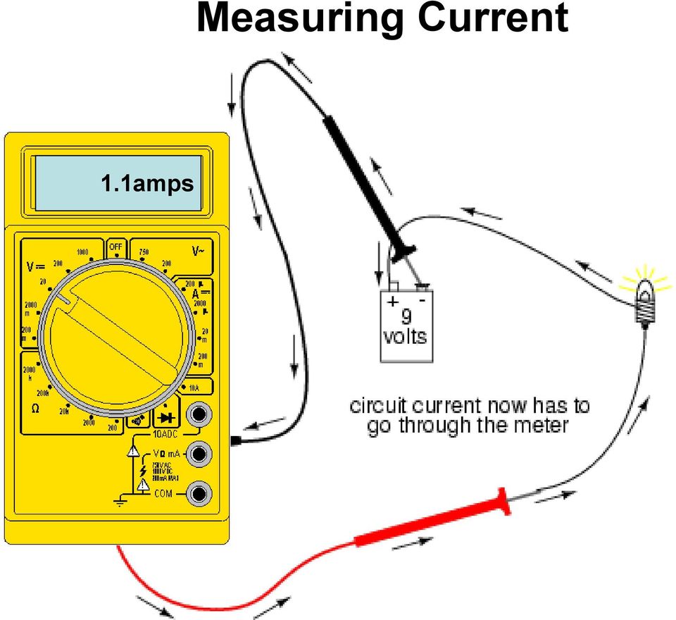
15 Measuring Current Current (amps) is the flow of electrical charge though a component or conductor Current is measured in amps or amperes Disconnect power source before testing Disconnect completed circuit at end of circuit Place multimeter in series with circuit Reconnect power source and turn ON Select highest current setting and work your way down.

16 Measuring Current

17 1.1amps Measuring Current
18 Review A meter capable of checking for voltage, current, and resistance is called a multimeter, When measuring Voltage the multimeter must be connected to two points in a circuit in order to obtain a good reading. Be careful not to touch the bare probe tips together while measuring voltage, as this will create a short-circuit! Never read Resistance or test for Continuity with a multimeter on a circuit that is energized. When measuring Current the multimeter must be connected in a circuit so the electrons have to flow through the meter Multimeters have practically no resistance between their leads. This is intended to allow electrons to flow through the meter with the least possible difficulty. If this were not the case, the meter would add extra resistance in the circuit, thereby affecting the current

Table of Contents. The Basics of Electricity 2. Using a Digital Multimeter 4. Testing Voltage 8. Testing Current 10. Testing Resistance 12
 Table of Contents The Basics of Electricity 2 Using a Digital Multimeter 4 IDEAL Digital Multimeters An Introduction The Basics of Digital Multimeters is designed to give you a fundamental knowledge of
The Basics of Digital Multimeters
 IDEAL INDUSTRIES INC. The Basics of Digital Multimeters A guide to help you understand the basic Features and Functions of a Digital Multimeter. Author: Patrick C Elliott Field Sales Engineer IDEAL Industries,
Instruction Manual. 2in1 LAN Tester & Multimeter. Model: LA-1011
 Instruction Manual 2in1 LAN Tester & Multimeter Model: LA-1011 1 Contents Introduction... Features... Safety Precautions.. Meter Description... Electrical Specification... Operation.. AutoRanging Multimeter.
User's Guide. True RMS Industrial Multimeter
 User's Guide 97650 True RMS Industrial Multimeter Ω C ã F ã 10A V µ 10A V ã ã ma A Introduction This meter measures AC/DC Voltage, AC/DC Current, Resistance, Capacitance, Frequency (electrical & electronic),
Essential Electrical Concepts
 Essential Electrical Concepts Introduction Modern vehicles incorporate many electrical and electronic components and systems: Audio Lights Navigation Engine control Transmission control Braking and traction
ANALOG AND DIGITAL METERS ANALOG VS. DIGITAL METERS VOLTMETERS ANALOG AND DIGITAL
 ANALOG VS. DIGITAL METERS Ultimately, your diagnosis of vehicle electrical system problems will come down to using a voltmeter, ammeter, or ohmmeter to pinpoint the exact location of the problem. There
Manual Ranging MultiMeter
 Owner s Manual Manual Ranging MultiMeter Model 82345 CAUTION: Read, understand and follow Safety Rules and Operating Instructions in this manual before using this product.! Safety! Operation! Maintenance!
AutoRanging Digital MultiMeter
 Owner's Manual AutoRanging Digital MultiMeter Model No. 82139 CAUTION: Read, understand and follow Safety Rules and Operating Instructions in this manual before using this product. Safety Operation Maintenance
Electrical Fundamentals Module 3: Parallel Circuits
 Electrical Fundamentals Module 3: Parallel Circuits PREPARED BY IAT Curriculum Unit August 2008 Institute of Applied Technology, 2008 ATE310- Electrical Fundamentals 2 Module 3 Parallel Circuits Module
Current Electricity Lab Series/Parallel Circuits. Safety and Equipment Precautions!
 Current Electricity Lab Series/Parallel Circuits Name Safety and Equipment Precautions! Plug in your power supply and use ONLY the D.C. terminals of the power source, NOT the A. C. terminals. DO NOT touch
Auto-ranging Digital Multimeter 52-0052-2 INSTRUCTION MANUAL
 Auto-ranging Digital Multimeter 52-0052-2 INSTRUCTION MANUAL WARNING: READ AND UNDERSTAND THIS MANUAL BEFORE USING YOUR MULTIMETER. FAILURE TO UNDERSTAND AND COMPLY WITH WARNINGS AND OPERATING INSTRUCTIONS
Time Propane Pressure Drop Test Sign-Off Sheet
 Time Propane Pressure Drop Test Sign-Off Sheet Printed Technician Name Address Social Security Number Telephone Number City State Zip Code Time Pressure Drop Test Conducted at the Range Did the Candidate:
SUBJECT: How to wire a motor starter Number: AN-MC-004 Date Issued: 2/08/2005 Revision: Original
 SUBJECT: How to wire a motor starter Number: AN-MC-004 Date Issued: 2/08/2005 Revision: Original A motor starter is a combination of devices to allow an induction motor to start, run and stop according
PHYSICS 111 LABORATORY Experiment #3 Current, Voltage and Resistance in Series and Parallel Circuits
 PHYSCS 111 LABORATORY Experiment #3 Current, Voltage and Resistance in Series and Parallel Circuits This experiment is designed to investigate the relationship between current and potential in simple series
User Guide. Model 380260 Insulation Tester / Megohmmeter
 User Guide Model 380260 Insulation Tester / Megohmmeter Introduction Congratulations on your purchase of Extech s Insulation Tester/Megohmmeter. The Model 380260 provides three test ranges plus continuity
Model UT201/202: OPERATING MANUAL. Table of Contents
 Table of Contents Title Overview Unpacking Inspection Safety Information Rules For Safe Operation International Electrical Symbols The Meter Structure Rotary Switch Functional Buttons The Effectiveness
7 FUNCTION DIGITAL MULTIMETER
 7 FUNCTION DIGITAL MULTIMETER 90899 OPERATING INSTRUCTIONS 3491 Mission Oaks Blvd., Camarillo, CA 93011 Visit our Web site at http://www.harborfreight.com Copyright 2004 by Harbor Freight Tools. All rights
Power Supplies. Overview. Measuring Electricity. Understanding Electricity. Two Types of Current. Powering the PC
 Overview Power Supplies Chapter 7 In this chapter, you will learn to Explain the basics of electricity Provide proper power and cooling to the PC Troubleshoot electrical problems Measuring Electricity
Experiment 8 Series-Parallel Circuits
 Experiment 8 Series-Parallel Circuits EL 111 - DC Fundamentals By: Walter Banzhaf, E.K. Smith, and Winfield Young University of Hartford Ward College of Technology Objectives: 1. For the student to measure
Troubleshooting Guide, Freedom and Fleet Power Inverter/Chargers
 Technical Note Freedom/Fleet Power 512-0084-01-01 Rev 1 Troubleshooting Guide, Freedom and Fleet Power Inverter/Chargers Overview This document is a guide for troubleshooting inverters, battery chargers,
Seven function digital multimeter
 Seven function digital multimeter 98025 Set up And Operating Instructions Distributed exclusively by Harbor Freight Tools. 3491 Mission Oaks Blvd., Camarillo, CA 93011 Visit our website at: http://www.harborfreight.com
TECHNICAL SERVICE DEPARTMENT Technical Service Bulletin 1-800-432-8373. Tankless Electric (RTE) Troubleshooting
 Troubleshooting") Sequence of Operations 1 Power supply and field wiring block 2 Energy Cut Off (ECO) 3 Water flow plunger and cold inlet 4 Magnetic flow switch 5 Water temperature thermistor 6 Control panel and circuit
Sequence of Operations 1 Power supply and field wiring block 2 Energy Cut Off (ECO) 3 Water flow plunger and cold inlet 4 Magnetic flow switch 5 Water temperature thermistor 6 Control panel and circuit
Basic voltmeter use. Resources and methods for learning about these subjects (list a few here, in preparation for your research):
:") Basic voltmeter use This worksheet and all related files are licensed under the Creative Commons ttribution License, version 1.0. To view a copy of this license, visit http://creativecommons.org/licenses/by/1.0/,
Basic voltmeter use This worksheet and all related files are licensed under the Creative Commons ttribution License, version 1.0. To view a copy of this license, visit http://creativecommons.org/licenses/by/1.0/,
LAB2 Resistors, Simple Resistive Circuits in Series and Parallel Objective:
 LAB2 Resistors, Simple Resistive Circuits in Series and Parallel Objective: In this lab, you will become familiar with resistors and potentiometers and will learn how to measure resistance. You will also
HOW TO USE MULTIMETER. COMPILE BY: Dzulautotech
 HOW TO USE MULTIMETER COMPILE BY: Dzulautotech 1. GENERAL Electricity is absolutely necessary for an automobile. It is indispensable when the engine is started, the air fuel mixture is ignited and exploded,
Model UT33A: OPERATING MANUAL Table of Contents (1)
") Table of Contents (1) Title Overview Unpacking Inspection Safety Information Rules For Safe Operation International Electrical Symbols The Meter structure Functional Buttons LCD Display Measurement Operation
Table of Contents (1) Title Overview Unpacking Inspection Safety Information Rules For Safe Operation International Electrical Symbols The Meter structure Functional Buttons LCD Display Measurement Operation
ABCs of DMMs Multimeter features and functions explained Application Note
 ABCs of DMMs Multimeter features and functions explained Application Note Digital multimeters offer a wide selection of features. Choosing the right meter for the job can be challenging unless you know
UT202A Operating Manual. Contents
 Title Contents Page Overview Unpacking Inspection Safety Information Rules for Safe Operation International Electrical Symbols The Meter Structure Functional Buttons and auto power off Display Symbols
rpsa FIRE PROTECTION ENGINEERS
 R.P. SCHIFILITI ASSOCIATES, INC. P.O. Box 297 Reading, Massachusetts 01867-0497 USA 781.944.9300 Fax / Data 781.942.7500 Telephone Sample Fire Alarm System Calculations 1. A fire alarm manufacturer specifies
Experiment NO.3 Series and parallel connection
 Experiment NO.3 Series and parallel connection Object To study the properties of series and parallel connection. Apparatus 1. DC circuit training system 2. Set of wires. 3. DC Power supply 4. Digital A.V.O.
Owner s Manual & Safety Instructions
 Owner s Manual & Safety Instructions Save This Manual Keep this manual for the safety warnings and precautions, assembly, operating, inspection, maintenance and cleaning procedures. Write the product s
3 Slot Payphone Controller
 5A2 3 Slot Payphone Controller The 3 Slot Payphone -- Part of American History Building a Coin Relay Controller Version S1BX Instruction Manual and Safety Precautions It is very important that for your
TECHNICAL SPECIFICATIONS FOR 1.5 KVA ONLINE UPS
 Capacity Technology Inverter Technology Noise Level Operating Temperature Humidity Harmonic Distortion Total DC bus voltage Battery recharge time (After Complete discharge) to 100% charge Crest Factor
TROUBLESHOOTING, REPAIR, AND REPLACEMENT GUIDE FOR MODEL #19300 BATTERY CHARGER PLEASE SAVE THESE IMPORTANT SAFETY INSTRUCTIONS
 *35827* TROUBLESHOOTING, REPAIR, AND REPLACEMENT GUIDE FOR MODEL #19300 BATTERY CHARGER PLEASE SAVE THESE IMPORTANT SAFETY INSTRUCTIONS For correct operation of the equipment, it is important to read and
IDEAL INDUSTRIES, INC. TECHNICAL MANUAL MODELS: 61-763 61-765
 IDEAL INDUSTRIES, INC. TECHNICAL MANUAL MODELS: 61-763 61-765 The Service Information provides the following information: Precautions and safety information Specifications Performance test procedure Calibration
Battery Power Inverters
 Battery Power Inverters Renogy 500W 1000W 2000W Pure Sine Wave Inverter Manual 2775 E. Philadelphia St., Ontario, CA 91761 1-800-330-8678 1 Version 1.1 Important Safety Instructions Please save these instructions.
ELECTRONIC BOARDS - SUPRA
 ELECTRONIC BOARDS - SUPRA INDEX TROUBLESHOOTING BOARD SOURCE INTERCONNECTION C.E. INTERFACE PH INTERFACE HARD SWITCH RELAYS 32-OUTPUT CARD BOARD # 7520 # TROUBLESHOOTING BOARD 12V CONNECTIONS: CONNECTOR
DIGITAL MULTIMETER OPERATION MANUAL ITEM 98674 DIGITAL MULTIMETER CONTENTS
 CONTENTS ITEM 98674 OPERATION MANUAL CONTENTS 1. SAFETY INFORMATION 1 1.1 PRELIMINARY 1 1.2 DOS AND DON TS 2 1.3 SYMBOLS 3 1.4 MAINTENANCE 4 2. DESCRIPTION 6 2.1 NAMES OF PARTS 7 2.2 SWITCH, BUTTONS AND
Checking Capacitor Banks for Failed Capacitors
 Checking Capacitor Banks for Failed Capacitors Introduction This technical note provides background information on capacitance testing of medium voltage double bushing capacitors commonly used in capacitor
Test Before Touch Easier Said Than Done. Ken Crawford, DuPont Kent Haggerty, Dupont
 Test Before Touch Easier Said Than Done Ken Crawford, DuPont Kent Haggerty, Dupont Overview Test Before Touch (TBT) Principles Key Learnings by One Company One Method for Performing a TBT Induced Voltages
1993 ACCESSORIES & EQUIPMENT Volkswagen Instrument Panels. Volkswagen; EuroVan, Passat
 Article Text Saturday, March 18, 2000 10:33PM ARTICLE BEGINNING 1993 ACCESSORIES & EQUIPMENT Volkswagen Instrument Panels Volkswagen; EuroVan, Passat DESCRIPTION & OPERATION Instrument cluster for most
GROUND DETECTION CIRCUITS FOR STATIONARY APPLICATIONS (IN PLAIN DOWN TO EARTH LANGUAGE)
") GROUND DETECTION CIRCUITS FOR STATIONARY APPLICATIONS (IN PLAIN DOWN TO EARTH LANGUAGE) Matthew Theriault Designer Hindle Power Inc. Easton, PA SCOPE AND PURPOSE OF THE PAPER Why do we bother to monitor
GROUND DETECTION CIRCUITS FOR STATIONARY APPLICATIONS (IN PLAIN DOWN TO EARTH LANGUAGE) Matthew Theriault Designer Hindle Power Inc. Easton, PA SCOPE AND PURPOSE OF THE PAPER Why do we bother to monitor
HM-W536 Install Guide
 HM-W536 Install Guide 9/13/2013 IMPORTANT SAFETY INSTRUCTIONS Warning - When using electrical devices, basic safety precautions should be followed to reduce the risk of fire, electrical shock or injury.
72-7730 72-7732 Intelligent Digital Multimeters
 72-7730 72-7732 Intelligent Digital Multimeters Model 72-7730/72-7732 OPERATING MANUAL TABLE OF CONTENTS CHAPTER TITLE PAGE 1. Before You Start Overview Inspection Safety Information Rules For Safe Operation
Lab 3 - DC Circuits and Ohm s Law
 Lab 3 DC Circuits and Ohm s Law L3-1 Name Date Partners Lab 3 - DC Circuits and Ohm s Law OBJECTIES To learn to apply the concept of potential difference (voltage) to explain the action of a battery in
Tips for connecting 24-volt power
 Digital Designer s Guide Application NoteAN0604D Revision B Tips for connecting 24-volt power This application note covers choosing a transformer and connecting 24 volt AC power to a KMC Controls DDC controller.
10 Multimeter. Users Manual
 10 Multimeter Users Manual 1991-2001 Fluke Corporation, All rights reserved. Printed in USA All product names are trademarks of their respective companies. 10 MULTIMETER m m Mk SELECT RANGE OFF VDC VAC
Lab E1: Introduction to Circuits
 E1.1 Lab E1: Introduction to Circuits The purpose of the this lab is to introduce you to some basic instrumentation used in electrical circuits. You will learn to use a DC power supply, a digital multimeter
PS4-24 OWNERS MANUAL 24 VAC 90 WATT WALL MOUNTED CCTV POWER SUPPLY
 PS4-24 OWNERS MANUAL 24 VAC 90 WATT WALL MOUNTED CCTV POWER SUPPLY 7320 Ashcroft, Suite 104 Houston, Texas 77081 p: 713-772-1404 f: 713-772-7360 e: [email protected] www.juicegoose.com 06-06 CONGRATULATIONS
Electrical Diagnostic Tools
 Electrical Diagnostic Tools Learning Objectives: 1. Explain what to look for when making a visual inspection. 2. Show the proper techniques for using a jumper wire. 3. Explain the advantages and features
SERVICE & OPERATING MANUAL ELECTRONIC LEAK DETECTOR 032-044-000 032-045-000 WARNING 12-32 VDC
 SERVICE & OPERATING MANUAL ELECTRONIC LEAK DETECTOR 032-044-000 032-045-000 } 12-32 VDC Specifications 032-044-000 and 032-045-000 WARNING Hazardous voltage. This Leak Detector is an electrical device.
Electrical Circuit Theory
 Electrical Circuit Theory Learning Objectives: 1. Review the basic electrical concepts of voltage, amperage, and resistance. 2. Review the components of a basic automotive electrical circuit. 3. Introduce
SERIES-PARALLEL DC CIRCUITS
 Name: Date: Course and Section: Instructor: EXPERIMENT 1 SERIES-PARALLEL DC CIRCUITS OBJECTIVES 1. Test the theoretical analysis of series-parallel networks through direct measurements. 2. Improve skills
AP Physics Electricity and Magnetism #4 Electrical Circuits, Kirchoff s Rules
 Name Period AP Physics Electricity and Magnetism #4 Electrical Circuits, Kirchoff s Rules Dr. Campbell 1. Four 240 Ω light bulbs are connected in series. What is the total resistance of the circuit? What
How To Use A Cdm250 Digital Multimeter
 User Manual CDM250 Digital Multimeter 070-6736-03 Copyright Tektronix, Inc. 1987. All rights reserved. Tektronix products are covered by U.S. and foreign patents, issued and pending. Information in this
W03 Analysis of DC Circuits. Yrd. Doç. Dr. Aytaç Gören
 W03 Analysis of DC Circuits Yrd. Doç. Dr. Aytaç Gören ELK 2018 - Contents W01 Basic Concepts in Electronics W02 AC to DC Conversion W03 Analysis of DC Circuits (self and condenser) W04 Transistors and
Experiment #5, Series and Parallel Circuits, Kirchhoff s Laws
 Physics 182 Summer 2013 Experiment #5 1 Experiment #5, Series and Parallel Circuits, Kirchhoff s Laws 1 Purpose Our purpose is to explore and validate Kirchhoff s laws as a way to better understanding
Measuring Electric Phenomena: the Ammeter and Voltmeter
 Measuring Electric Phenomena: the Ammeter and Voltmeter 1 Objectives 1. To understand the use and operation of the Ammeter and Voltmeter in a simple direct current circuit, and 2. To verify Ohm s Law for
POWER SUPPLY MODEL XP-15. Instruction Manual ELENCO
 POWER SUPPLY MODEL XP-15 Instruction Manual ELENCO Copyright 2013 by Elenco Electronics, Inc. REV-A 753020 All rights reserved. No part of this book shall be reproduced by any means; electronic, photocopying,
AVO410. Digital multimeter Digitale Multimeter Multimèter numérique Multímetro digitales Digitale multimeter
 mm AVO410 Digital multimeter Digitale Multimeter Multimèter numérique Multímetro digitales Digitale multimeter User manual Bedienungsanleitung Manuel utilisateur Guía del usuario Gebruikershandleiding
Companion Service Guide
 Companion Service Guide This Service Guide contains: Troubleshooting Replacement Instructions Contact Information Golden Technologies 401 Bridge Street Old Forge, PA 18518 Toll-free: 800-624-6374 Fax:
Field-Tested and Fixed in Five!
 Technical Newsletter Special Issue Published by Rain Bird Sales, Inc. Turf Products Late Spring 2000 IN THIS ISSUE: Controller Troubleshooting ESP Controller Improvements RASTER Testing Field-Tested and
Fig. 1 Analogue Multimeter Fig.2 Digital Multimeter
 ELECTRICAL INSTRUMENT AND MEASUREMENT Electrical measuring instruments are devices used to measure electrical quantities such as electric current, voltage, resistance, electrical power and energy. MULTIMETERS
OHM S LAW AND RESISTANCE
 OHM S LAW AND RESISTANCE Resistance is one of the basic principles of Ohm s law, and can be found in virtually any device used to conduct electricity. Georg Simon Ohm was a German physicist who conducted
The table below lists the symbols used on the Clamp and/or in this manual. Important Information. See manual.
 i800 AC Current Clamp Instruction Sheet Introduction The i800 AC Current Clamp, the Clamp, has been designed for use with multimeters, recorders, power analyzers, safety testers, etc., for accurate non-intrusive
LocoNet, the Digitrax Difference
 LocoNet, the Digitrax Difference LocoNet is Digitrax's method of communication between LocoNet compatible devices on a model railroad layout. LocoNet Compatible devices are designed to work together on
The Charging System. Section 5. Charging System. Charging System. The charging system has two essential functions:
 The Charging System Charging System The charging system has two essential functions: Generate electrical power to run the vehicle s electrical systems Generate current to recharge the vehicle s battery
victron energie USER MANUAL GEBRUIKSAANWIJZING GEBRAUCHSANWEISUNG Victron Atlas 12/850
 victron energie USER MANUAL GEBRUIKSAANWIJZING GEBRAUCHSANWEISUNG Victron Atlas 12/850 SECTIONS ENGLISH 1 NEDERLANDS 27 DEUTSCH 55 This page intentionally left blank. ENGLISH USER MANUAL Victron Atlas
Configuring the 930A for Common PBX Metallic Signaling Interfaces
 Product: 930A Communications Test Set APPLICATION NOTE # Configuring the 930A for Common PBX Metallic Signaling Interfaces TABLE OF CONTENTS Introduction...1 Primer...1 LOOP START...2 General...2 Trunk
Troubleshooting accelerometer installations
 Troubleshooting accelerometer installations Accelerometer based monitoring systems can be tested to verify proper installation and operation. Testing ensures data integrity and can identify most problems.
Model UT61A/61B/61C/61D/61E: OPERATING MANUAL. Table of Contents
 P/N:110401103671 Table of Contents Title Overview Unpacking Inspection Safety Information Rules For Safe Operation International Electrical Symbols The Meter Structure Rotary Switch Functional Buttons
First Year (Electrical & Electronics Engineering)
") Z PRACTICAL WORK BOOK For The Course EE-113 Basic Electrical Engineering For First Year (Electrical & Electronics Engineering) Name of Student: Class: Batch : Discipline: Class Roll No.: Examination Seat
Z PRACTICAL WORK BOOK For The Course EE-113 Basic Electrical Engineering For First Year (Electrical & Electronics Engineering) Name of Student: Class: Batch : Discipline: Class Roll No.: Examination Seat
DC Circuits (Combination of resistances)
") Name: Partner: Partner: Partner: DC Circuits (Combination of resistances) EQUIPMENT NEEDED: Circuits Experiment Board One Dcell Battery Wire leads Multimeter 100, 330, 1k resistors Purpose The purpose
Name: Partner: Partner: Partner: DC Circuits (Combination of resistances) EQUIPMENT NEEDED: Circuits Experiment Board One Dcell Battery Wire leads Multimeter 100, 330, 1k resistors Purpose The purpose
User Manual for CH-PFC76810
 AA Portable Power Corp www.batteryspace.com, Email: [email protected] User Manual for CH-PFC76810 1. Overview The CH-PFC76810 charger is suitable for charging lithium ion battery packs such as those
Fire Alarm Control Panel. Family. Operating Manual
 Fire Alarm Control Panel Family Operating Manual CONTENTS System Description AH-03312 System Characteristics... Fire Signal Receiving Board Description-4L... Fire Signal Receiving Board Description-8L...
Electronics. Basic Concepts. Yrd. Doç. Dr. Aytaç GÖREN Yrd. Doç. Dr. Levent ÇETİN
 Electronics Basic Concepts Electric charge Ordinary matter is made up of atoms which have positively charged nuclei and negatively charged electrons surrounding them. Charge is quantized as the subtraction
Battery Chargers. Revised 8/00 Form Number 56041170 FORM NO. 56041170 / BATTERY CHARGER SERVICE MANUAL / PARTS LIST - 45
 Battery Chargers SERVICE MANUAL / PARTS LIST AUTOMATIC Advance MODELS 0980, 098, 797, 8809, 90, 880, 880, 099, 08,, 09788, 098, 7, 097, 70, 790, 889 Lester MODELS 007,, 8, 8, 89, 80, 9, 00, 00, 008 MANUAL
Maximum value. resistance. 1. Connect the Current Probe to Channel 1 and the Differential Voltage Probe to Channel 2 of the interface.
 Series and Parallel Circuits Computer 23 Components in an electrical circuit are in series when they are connected one after the other, so that the same current flows through both of them. Components are
HVAC Clamp Meter. Users Manual
 902 HVAC Clamp Meter Users Manual PN 2547887 May 2006 Rev. 1, 3/07 2006-2007 Fluke Corporation. All rights reserved. Printed in China. All product names are trademarks of their respective companies. LIMITED
STUDY GUIDE: ELECTRICITY AND MAGNETISM
 319 S. Naperville Road Wheaton, IL 60187 www.questionsgalore.net Phone: (630) 580-5735 E-Mail: [email protected] Fax: (630) 580-5765 STUDY GUIDE: ELECTRICITY AND MAGNETISM An atom is made of three
CONSTRUCTING A VARIABLE POWER SUPPLY UNIT
 CONSTRUCTING A VARIABLE POWER SUPPLY UNIT Building a power supply is a good way to put into practice many of the ideas we have been studying about electrical power so far. Most often, power supplies are
DORMA MODEL PS-406BB POWER SUPPLY INSTALLATION INSTRUCTIONS
 Features: INSTALLATION Install in accordance with NFPA 70. DORMA MODEL PS-406BB POWER SUPPLY INSTALLATION INSTRUCTIONS Up to 1.95 Amps Load Capacity Class 2 Rated Outputs Overload, Over Voltage, and Short
UPS Applications and VRLA Battery Sizing
 TECHNICAL BULLETIN 41-7334 UPS Applications and VRLA Battery Sizing 41-7334/0213/CD www.cdtechno.com The uninterruptable power system (UPS) is used to protect critical equipment and processes from the
INTRODUCTION. The data provided is for The Standard Products and any variation will be dealt with at the end of this manual.
 INTRODUCTION The information provided herein covers the range of products known as the 'Sensor 901' series. The range of equipment is designed to meet the requirements of BS 5839 parts 1 & 4 1988. The
Ground Resistance Clamp On Tester
 USER MANUAL Ground Resistance Clamp On Tester MODEL 382357 Introduction Congratulations on your purchase of Extech s 382357 Ground Resistance Tester. This Clamp on device allows the user to measure ground
Model UT71A/B OPERATING MANUAL
 Model UT71A/B OPERATING MANUAL CHAPTER TITLE PAGE 1. 2. Before You Start Overview Unpacking Inspection Safety Information Rules For Safe Operation International Electrical Symbols Getting Acquainted Turning
3.- What atom s particle moves through a conductor material? 4.- Which are the electric components of an elemental electric circuit?
 1.- What is electricity? 2.- Write down the name of the atom s particles. 3.- What atom s particle moves through a conductor material? 4.- Which are the electric components of an elemental electric circuit?
A4 Air Conditioning Control Circuit Troubleshooting Rev 7, 6/18/2009
 A4 Air Conditioning Control Circuit Troubleshooting Rev 7, 6/18/2009 ** This guide is for Manual Air Conditioning (as opposed to Climatronic A/C or Climatic A/C), with two 2-speed fans on Volkswagen A4's
Lab 3 Rectifier Circuits
 ECET 242 Electronic Circuits Lab 3 Rectifier Circuits Page 1 of 5 Name: Objective: Students successfully completing this lab exercise will accomplish the following objectives: 1. Learn how to construct
BATTERY BOX INSTALLATION WARNING WARNING CAUTION ATTENTION AVERTISSEMENT ADVERTENCIA PRECAUCIÓN SOLBBOX12V CARTON INVENTORY COMPLETED OVERVIEW
 WARNING CARTON INVENTORY CAUTION with: Charger, Cable 15', Fuses (2), Battery Strap and Strain Relief (2) Model SOLBBOX 12V Battery Not Included AVERTISSEMENT ATTENTION DC Power Adapter 12Vdc to 32Vdc
Multimeter measurements on variable frequency drives using the new Fluke 289 DMM
 Multimeter measurements on variable frequency drives using the new Fluke 289 DMM Application Note Editor s note: For similar instructions using the Fluke 87V DMM, reference Fluke article 12345. In the
HOW TO CORRECTLY CONNECT DEEP CYCLE BATTERIES AND CHOOSE THE RIGHT CABLE SIZING
 HOW TO CORRECTLY CONNECT DEEP CYCLE BATTERIES AND CHOOSE THE RIGHT CABLE SIZING There are several ways to wire multiple batteries to achieve the correct battery voltage or capacity for a particular DC
Georgia Performance Standards Framework for Physical Science 8 th Grade. Powering Satellites
 The following instructional plan is part of a GaDOE collection of Unit Frameworks, Performance Tasks, examples of Student Work, and Teacher Commentary. Many more GaDOE approved instructional plans are
Cooling Fan Replacement September 2008 975-0455-01-01 Rev A1 Page 1 of 6
 975-0455-01-01 Rev A1 Page 1 of 6 0 I WARNING RI SK OF ELE CTRI CA L S HOCK DO NO T REM OVE COVER, NO USER SERVICEABLE PARTS INSIDE. STORED ENERG Y IN CAPACITOR. ALLOW AT LEAST 5 MINUTES AFTER DISCONNECTI
R448 & R448 V50 A.V.R.
 Armature + 6- This manual is to be given to the end user F1 ST5 Field Slow fuse 250V 10 A with LAM without LAM 10 Yellow 11 Red 12 Black 9 Green X2 Z1 X1 Z2 E+ E- 0V 110 22 ST3 requency ST10 50Hz 60Hz
Total solder points: 18 Difficulty level: beginner 1 2 3 4 5 advanced UNIVERSAL POWER SUPPLY 5-14DC / 1A K2570 ILLUSTRATED ASSEMBLY MANUAL
 Total solder points: 18 Difficulty level: beginner 1 2 3 4 5 advanced UNIVERSAL POWER SUPPLY 5-14DC / 1A K2570 The easy way to power your projects. ILLUSTRATED ASSEMBLY MANUAL H2570IP-1 Features & Specifications
Table of Contents. Page No.
 Table of Contents Title Page No. INTRODUCTION... 2 SAFETY PRECAUTIONS/S... 2 SPECIFICATIONS... 3 CONTROLS AND INDICATORS... 8 TESTING PROCEDURES... 10 AUXILIARY FUNCTIONS... 17 BATTERY AND FUSE REPLACEMENT...
THE BREADBOARD; DC POWER SUPPLY; RESISTANCE OF METERS; NODE VOLTAGES AND EQUIVALENT RESISTANCE; THÉVENIN EQUIVALENT CIRCUIT
 THE BREADBOARD; DC POWER SUPPLY; RESISTANCE OF METERS; NODE VOLTAGES AND EQUIVALENT RESISTANCE; THÉVENIN EQUIVALENT CIRCUIT YOUR NAME LAB MEETING TIME Reference: C.W. Alexander and M.N.O Sadiku, Fundamentals