KBPC-240D (Part Nos and 9342) Installation and Operation Manual Supplement
|
|
|
- Garey Parrish
- 9 years ago
- Views:
Transcription
1 The Right Control for Your Application NW 39 Street, Coral Springs, FL Telephone: ; Fax: KB Electronics, Inc. KBPC-240D (Part Nos and 9342) Installation and Operation Manual Supplement This supplement is for Model KBPC-240D Installation and Operation Manual (Part No. A40400) until the new manual is available. The manual must be read and understood before operating this drive. For further assistance, contact our Sales Department at or Toll Free at (outside Florida). PRODUCT UPDATES Run Relay Added SMT Construction This drive has been converted to Surface Mount Technology (SMT). All trimpots have been moved and aligned at the top of the PC board. A Run Relay has been added, which can be used to turn equipment "on" or "off" as a function of drive status (Off, Stop, Run). The General Performance Specifications, Electrical Ratings, Mechanical Specifications, and Connection Diagrams have not changed. The Parts List (Table 11, on pages 17 and 18) and Schematic (Figure 16, on page 19) in the manual no longer apply to this drive and should not be used. See Figure 1 for the location of the Run Relay Output Contacts, Trimpots, and Jumpers (replaces Figure 1, on page 3, in the manual). See Figure 1 for the Run Relay Output Contacts ratings. See Table 1 for the drive operating conditions and Run Relay Output Contacts status. FIGURE 1 DRIVE LAYOUT TABLE 1 DRIVE OPERATING CONDITION AND RUN RELAY OUTPUT CONTACTS STATUS Drive Operating Condition Description Normally Open Contact Normally Closed Contact Power Off Main Power Disconnected Open Closed Run Mode Normal Drive Operation Closed Open Stop Mode Selected by Operator Open Closed Trip Drive Tripped Open Closed (A42144) Rev. D00 1/6/2010 Page 1 of 1
. All trimpots have been moved and aligned at the top of the PC board.")
2 T INSTALLATION AND OPERATING INSTRUCTIONS MODEL KBPC-240D KB Part No (Black Case) Part No (White Case) NEMA 4X, IP-65 SCR Speed and Torque Control Designed For DC Motors Rated 1/ VDC, 1/ VDC This control will not operate without installing the correct armature fuse supplied separately. Note: Product illustration is shown with optional Forward- Brake-Reverse and Run-Jog options. See Page 2 See Safety Warning on Page 2 The information contained in this manual is intended to be accurate. However, the manufacturer retains the right to make changes in design which may not be included herein. A COMPLETE LINE OF MOTOR DRIVES 1998 KB Electronics, Inc.

3 TABLE OF CONTENTS Section Page i. KBPC-240D Simplified Operating Instructions...1 ii. Safety Warning...2 I. General Information...2 II. Setting Selectable Jumpers...5 III. Mounting...9 IV. Wiring...10 V. Fusing...13 VI. Operation...13 VII. Trimpot Adjustments...14 VIII. Function Indicator Lamps...15 IX. Optional Accessories...15 X. Limited Warranty...22 TABLES 1. Electrical Ratings General Performance Specifications Setting AC Line Voltage with Jumper J2A and J2B Setting Armature Voltage with Jumper J Jumper J4 vs Motor Horsepower Current Limit Settings with.05 Ohm Plug-In-Horsepower Resistor Installed Terminal Block Wiring Information Relationship of AC Line Input and Motor Voltage with J2 and J3 Jumper Position Field Connections (Shunt Wound Motors Only) Armature Fuse Chart Parts List...17, 18 FIGURES 1. Control Layout Mechanical Specifications Motor Speed vs Potentiometer Rotation Preset Motor Speed vs Motor Load Motor Output Torque vs Potentiometer Rotation Motor Speed vs Applied Motor Load...7 7A. Captive Screw Tightened in Case B. Captive Screw Engaged in Front Cover Connection Diagram A. Full Voltage Field B. Half Voltage Field Tach-generator Connection Diagram Remote Potentiometer Analog Voltage Remote Start/Stop Switch Inhibit Circuit Enable Circuit Schematic Connection Diagram for KBPC-240D with KBSI-240D Signal Isolator Internal Connection Diagram Connection Diagrams for Available Options...21 ii

4 i. KBPC-240D SIMPLIFIED OPERATING INSTRUCTIONS IMPORTANT You must read these simplified operating instructions before you proceed. These instructions are to be used as a reference only and are not intended to replace the detailed instructions provided herein. You must read the Safety Warning on page 2 before proceeding. 1. CONNECTIONS. A. AC Line Wire AC line voltage to terminals L1 and L2. Be sure jumpers J2A and J2B are both set to the correct input line voltage 115 or 230 VAC. Connect ground wire (earth) to green ground screw on case. B. Motor. 1. Permanent Magnet (PM) Type. Connect motor armature leads to A1(+) and A2( ). Be sure jumper J3 is set to the proper position 90V" for 90 volt DC motors and 180V" for 180 volt DC motors. Note: 180 volt DC motors must be used with 230 VAC line, 90 volt motors can be used with a 230 VAC or 115 VAC line. See sec. II, C, on page Shunt Wound Motors. Connect motor armature as above. Connect full voltage shunt field wires (90 volt motors with 100 volt fields and 180 volt motors with 200 volt fields) to F1 and F2. Connect half voltage field wires (90 volt motors with 50 volt fields and 180 volt motors with 100 volt fields) to F1 and L1. See sec. IV, C, on page SPEED OR TORQUE MODE. Jumper J1 is factory set for speed control operation (SPD). For torque control, set J1 to TRQ position. See sec. II, A, on page MOTOR CURRENT. Jumper J4 is factory set for 10 amp motors (10A). For lower amperage motors, place J4 in the proper position. See section II, D, on page 8 for details. Note: The factory setting for Current Limit is 150% of the nominal current setting, e.g., if J4 is selected for 10 amps, the actual CL setting will be 15 amps. 4. TRIMPOT SETTINGS. All trimpots have been factory set in accordance with figure 1, page 3 and table 1, page DIAGNOSTIC LED s. After power is turned on, observe LED s to verify proper control function. See sec. VIII on page ARMATURE FUSE. The correct size armature fuse must be installed, depending on the rating of the motor. Control will not operate if fuse is not installed. See section V, B on page 13 and table 6 on page START/STOP SWITCH. The KBPC contains a built-in manual start/stop switch. This switch must be used to start the control each time AC power is lost. To override this function see sec IV, G, p
 to green ground screw on case. B. Motor. 1. Permanent Magnet (PM) Type. Connect motor armature leads to A1(+) and A2( ).")
5 ii. SAFETY WARNING! PLEASE READ CAREFULLY This product should be installed and serviced by a qualified technician, electrician or electrical maintenance person familiar with its operation and the hazards involved. Proper installation, which includes wiring, mounting in proper enclosure, fusing or other overcurrent protection and grounding, can reduce the chance of electric shocks, fires or explosion in this product or products used with this product, such as electric motors, switches, coils, solenoids and/or relays. Eye protection must be worn and insulated adjustment tools must be used when working with control under power. This product is constructed of materials (plastics, metals, carbon, silicon, etc.) which may be a potential hazard. Proper shielding, grounding and filtering of this product can reduce the emission of radio frequency interference (RFI) which may adversely affect sensitive electronic equipment. If information is required on this product, contact our factory. It is the responsibility of the equipment manufacturer and individual installer to supply this safety warning to the ultimate user of this product. (SW effective 11/92) This control contains electronic Start/Stop and inhibit circuits that can be used to start and stop the control. However, these circuits are never to be used as safety disconnects since they are not fail-safe. Use only the AC line for this purpose. The input circuits of this control (potentiometer, start/stop, Inhibit) are not isolated from AC line. Be sure to follow all instructions carefully. Fire and/or electrocution can result due to improper use of this product. This product complies with all CE directives pertinent at the time of manufacture. Contact factory for detailed installation instructions and Declaration of Conformity. Installation of a CE approved RFI filter (KBRF-200A, KB P/N 9945A or equivalent) is required. Additional shielded motor cable and/or AC line cables may be required along with a signal isolator (KBSI-240D, KB P/N 9431 or equivalent). I. GENERAL INFORMATION. The KBPC Series Nema 4 X (IP-65) is a unidirectional SCR DC Motor Speed and Torque Control designed for applications requiring watertight integrity, including washdown. Its housing is ruggedly constructed of die cast aluminum, protected with an acrylic coating that provides excellent corrosion resistance. All switches are sealed with rubber boots and the main speed potentiometer contains a shaft seal. The electronics for the KBPC is state-of-the-art and includes short circuit and transient protection which provides the ultimate in reliability. Electronic overload protection prevents motor burnout and demagnetization of PM motors. The control can be operated in either the Speed or Torque mode via jumper selection. The current range, which is also jumper selectable, eliminates the necessity for calibration of IR Compensation and Current Limit for most applications. The KBPC also contains jumper selections for AC line voltage (230/115), DC armature voltage (180/90) and feedback type (armature/tach-generator). Standard features include armature fusing*, electronic start/stop and an LED indicator array for Power On, Stop and Overload (*fuse supplied separately). Although the KBPC is factory set for most applications, a variety of trimpots allow adjustment of the following parameters: Minimum and Maximum Speed, Acceleration, Deceleration, Current Limit, IR Comp, and Timed Current Limit. Optional features offered are: On/Off AC Line Switch, Forward-Brake-Reverse, Run-Stop-Jog, Input Signal Isolation, RFI Filtering, and Electronic Run- Brake Module. WARNING! Be sure to follow all instructions carefully. Fire or electrocution can result due to improper use of this product. Read Safety Warning. 2

6 FIG. 1 CONTROL LAYOUT (Illustrates Factory Setting of Jumpers and Approximate Trimpot Settings) 3

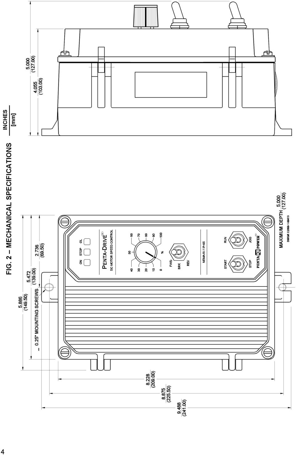
7 FIG. 2 MECHANICAL SPECIFICATIONS TM INCHES [mm] TM 4
8 TABLE 1 ELECTRICAL RATINGS Model Input Voltage (VAC) Max. AC Current (ARMS) Output Voltage (VDC) Max. DC Output Current (ADC) Max. HP, (KW) , (.75) KBPC-240D , (1.5) , (.75) TABLE 2 GENERAL PERFORMANCE SPECIFICATIONS Parameter AC Line Input Voltage (VAC ±10%,50/60 Hz) AC Line Frequency (Hz), # of Phases Arm Voltage Range at 115VAC Line (VDC) Arm Voltage Range at 230VAC Line (VDC) Field Voltage at 115VAC Line (VDC) Field Voltage at 230VAC Line (VDC) Horsepower Range at 115 VAC HP, (KW) Horsepower Range at 230 VAC HP, (KW) Ambient Temperature Range (ºC) Speed Range (Ratio) Arm Feedback Load Regulation (% Base Speed) Tach Feedback Load Regulation (% Set Speed) Line Regulation (% Base Speed) Current Ranges (ADC) ACCEL and DECEL Ranges (Sec.) MIN Speed Range (% Base Speed) MAX Speed Range (% Base Speed) IR Comp Range at 115VAC Line (VDC) IR Comp Range at 230VAC Line (VDC) CL Range (% Range Setting) Timed CL Range (Sec.) Voltage Following Linearity (% Base Speed) Specification 115 or /60, , /50 200/100 1/50 1, ( ) 1/25 2, ( ) :1 ±1 ±1 ± , 5.0, 7.5, ± Factory Setting II. SETTING SELECTABLE JUMPERS. The KBPC-240D has customer selectable jumpers which must be set before the control can be used. Bold indicates factory setting. See fig. 1, page 3 for location of jumpers. A. Control Mode Speed (SPD) or Torque (TRQ). Note: Factory setting for J1 is Speed mode. When Jumper J1 is placed in the TRQ SPD "SPD" position the drive will control motor speed as a linear function of the main potentiometer rotation, or analog voltage input. The range of output speed can be adjusted with the MIN and MAX trimpots. The motor will maintain the preset speed as long as the maximum load does not exceed the current limit set point. If the motor load exceeds the current limit setting, the Overload LED will turn on and the motor will stall. 5
 Field Voltage at 115VAC Line (VDC) Field Voltage at 230VAC Line (VDC) Horsepower Range at 115 VAC HP, (KW) Horsepower Range at 230 VAC HP, (KW) Ambient Temperature Range (ºC) Speed")
9 FIG. 3 MOTOR SPEED vs POTENTIOMETER ROTATION [SPEED MODE] FIG. 4 PRESET MOTOR SPEED vs MOTOR LOAD [SPEED MODE] When Jumper J1 is placed in the "TRQ" position, the drive will control motor torque as a linear function of main potentiometer rotation. If the motor load exceeds the torque setting, the motor will stall, the Overload LED will light, and the drive will apply a constant preset torque based on the potentiometer setting. The Overload LED will light when the load torque approaches the current limit set point. The torque limits are set via jumper J4 and the CL trimpot. (Note: When operating in the Torque Mode, Jumper J5 must be in the "NTCL" position or drive will shut down when CL Timer times out.) 6

10 FIG. 5 MOTOR OUTPUT TORQUE vs POTENTIOMETER ROTATION [TORQUE MODE] FIG. 6 MOTOR SPEED vs APPLIED MOTOR LOAD [TORQUE MODE] B. J2A, J2B Input AC Line Voltage Select proper input line voltage 115VAC or 230VAC by placing both J2A and J2B in the correct corresponding positions, "115V" or 230V. TABLE 3 SETTING AC LINE VOLTAGE WITH JUMPER J2A and J2B Control Set for 230 VAC (Factory Setting) C. J3 Armature Voltage Output and Tach-generator Feedback Select the desired armature voltage by placing J3 in the proper position 90V for VDC motors and 180V" for VDC motors. For 115VAC line input the armature voltage must be set to 90V. Control Set for 115 VAC 7

11 For 230VAC line input, the armature voltage is normally set to"180v". However, it is also possible to operate in a Step- Down Mode (90 130VDC motor with a 230VAC line) by setting J3 to "90". However, reduced performance may result. TABLE 4 SETTING ARMATURE VOLTAGE WITH JUMPER J3 Control Set for 180 VDC (Factory Setting) 180V 90V Control Set for 90 VDC 180V 90V If tach-generator feedback is to be used, J3 must be placed in the "T" position and an external DC tachgenerator must be connected. See section II, F, p. 9, and section IV, E on page 11 for additional information. D. J4 Armature Current Select the J4 position (2.5A, 5A, 7.5A, 10A) closest to the rated motor current. Note that the output is factory set to 150% of the J4 position (e.g. 15 amps in the 10A position and 11 amps in the 7.5 position, etc.). This setting can be readjusted using the CL trimpot (see section VII, E on page 14). TABLE 5 JUMPER J4 SETTING vs MOTOR HORSEPOWER JUMPER J4* Motor Horsepower Range 90 VDC 180 VDC 10.0 Amps Amps 3/ Amps 1/3 1/2 3/ Amps 1/6 1/4 1/3 1/2 Note: Jumper J4 is shown in the factory setting. Application Note Subfractional Horsepower Motors. For subfractional motors with current ratings below 2.5 amps, the KBPC can be modified as follows. Note: Before making this modification you must have a.05 ohm Plug-in Horsepower Resistor (KB P/N 9839). Carefully clip out the large power resistor R69 on the printed circuit board. The resistor location is indicated in fig. 1, p. 3.) Insert the.05 ohm Plug-in Horsepower Resistor into the two (2) pins located under the resistor R69. Each of the current selection values are now divided by 10. See table 6 below. TABLE 6 CURRENT LIMIT SETTINGS with.05 OHM PLUG-IN HORSEPOWER RESISTOR INSTALLED Original J4 Current Jumper Selection New J4 Current Jumper Selection New Current Limit Trimpot Range New Current Limit Trimpot Factory Setting 10.0 Amps 1.0 Amps Amps 1.50 Amps 7.5 Amps 0.75 Amps Amps 1.13 Amps 5.0 Amps 0.5 Amps Amps 0.75 Amps 2.5 Amps 0.25 Amps Amps 0.38 Amps E. J5 Current Limit Mode (Factory set for "TCL") This control contains electronic current limiting which limits the maximum DC current to the motor (the current limit set point is established with the selection of the J4 position and the setting of the CL trimpot). Two modes of current limit operation are provided: 8

12 1. Timed current limit "TCL": In this mode the drive will turn off after being in current limit for a preset time. The time period is adjustable with the TCL trimpot from seconds and is factory set for approximately seven (7) seconds. TCL provides electronic motor overload protection. Application Note: After the control times out in TCL, it can be reset using the Start Switch by setting the switch to the "STOP" position and then to "START," or by disconnecting and reconnecting the AC line. If the Start Switch is jumpered out, the control can be restarted after timing out in TCL, by disconnecting and reconnecting the AC line. Note, the Overload lamp will remain lighted until the control is reset. 2. Non-Timed Current Limit "NTCL": In this mode the drive will reach the preset current limit during overload and stay at that level until a fuse blows or the drive is manually turned off. If non-timed CL operation is desired, move jumper J5 from the factory set "TCL" position to the "NTCL" position. The NTCL position must be used when operating in the Torque Mode. See section II, A on page 5. F. J6 Tach-generator voltage (Note: Selection of this jumper position is not required if tach-generator feedback is not used.) If tach-generator feedback is used, select the J6 position (7V, 20/30V, 50V) which corresponds to the tach-generator voltage in Volts/1000 RPM. The selection of J6 position is based on a maximum motor speed of 1800 RPM. If other than standard tach-generator voltages and motor speeds are used, an external resistor (RT) may be used (1/2 watt rating). 1. Install resistor (RT) in series with either tach-generator lead. 2. Place J6 in "7V" position. 3. Calculate the value of (RT) as follows: J6 50V 20/30V 7V RT = [(1.64 x VT x S) - 20,000] ohms VT = Tach Voltage in Volts/1000 RPM { S = Base speed of motor in RPM Note: For tach-generator feedback, Jumper J3 must be in the "T" position. G. J7 Signal Input Voltage The output of this control is normally controlled with the main potentiometer. However, an Isolated analog voltage may also be used in place of a potentiometer. The control can be scaled for either a 0-5VDC or 0-10VDC by placing J7 in the appropriate position "5V" or "10V". The 10V scaling can be further adjusted with the "Max" trimpot. See section IV, F 2, on page 12 for wiring information. Note: If an Isolated input signal is not available an accessory Signal Isolator Model KBSI- 240D (KB P/N-9431) can be installed. The KBSI-240D accepts a wide range of signal voltage and current. An Installation Kit containing Auto/Man Switch and required wiring is also available (P/N 9377). III. MOUNTING Mount the control in a vertical position on a flat surface. Be sure to leave enough room below the bottom of the control to allow for the AC line and motor connections. Although the control is designed for outdoor and washdown use, care should be taken to avoid extremely hazardous locations where physical damage can occur. Note: Do not use this control in an explosion proof application. If the control is mounted in a closed, unventilated cabinet, remember to allow for proper heat dissipation. If full rating is required, a minimum enclosure size of 12" W x 24" H x 12" D should be used. Front Cover - The KBPC case is designed with a hinge so that when the front cover is open, all wiring stays intact. To open the cover, the four cover screws must be loosened, so they no longer are engaged in the case bottom. Note that these screws are captive and the front cover holes are threaded. After mounting and wiring, close the front cover, making sure all wires are contained within the enclosure and the gasket is in place around the cover lip. Tighten all four cover screws so that the gasket is slightly compressed. Do not overtighten. 9

13 FIG. 7A CAPTIVE SCREW TIGHTENED IN CASE FIG. 7B CAPTIVE SCREW ENGAGED IN FRONT COVER CAPTVE SCREW COVER GASKET CASE CAPTVE SCREW COVER GASKET CASE IV. WIRING. Warning! Read Safety Warning before attempting to use this control. Warning! To avoid erratic operation do not bundle AC Line and motor wires with potentiometer, voltage following, enable, inhibit or other signal wiring. Use shielded cables on all signal wiring over 12" (30 cm) Do not ground shield. Wire control in accordance with the National Electric Code requirements, and other codes that apply. Be sure to fuse each conductor which is not at ground potential. Do not fuse neutral or grounded conductors. Note: See section V, Fusing, on page 13. A separate AC line switch, or contactor, must be wired as a disconnect switch, so that the contacts open each ungrounded conductor. An accessory ON/OFF AC Line Switch (KB P/N 9341) may be installed in this control in lieu of, or in addition to, the Start/Stop Switch normally provided. The switch can be wired for double pole or single pole operation. (See fig. 8, for AC Line and Armature connection.) To maintain the watertight integrity of the control, be sure to use suitable watertight connectors and wiring, which are appropriate for the application. Two.875" (22.2 mm) knockout holes are provided for a standard 1/2" knockout connector (not supplied) for wiring. A watertight plug is provided if only one knockout is required. A. AC Line Connect AC Line to terminals L1 and L2. (Be sure jumpers J2A and J2B are set to the correct position to match the AC line input voltage. See table 8 on page 11. TABLE 7 TERMINAL BLOCK WIRING INFORMATION Terminal Block Designation Connection Designation Supply Wire Gauge* Minimum Maximum Maximum Tightening Torque (lbs inch) TB1 A1, A2, L1, L TB2 F1, F TB3 T+, T *Use Cu wire only (AWG) B. Motor Armature Connect motor armature to terminals A1 (+) and A2 ( ). (Be sure jumper J3 is set to closely match motor voltage. See table 8, p. 11.) WARNING! Do not wire switches or relays in series with the armature. Armature switching can cause catastrophic failure of motor and/or control. Do not bundle AC and motor wires with other wires (e.g., potentiometer, analog input, Forward- Brake-Reverse, etc.). FIG. 8 CONNECTION DIAGRAM 10

14 TABLE 8 RELATIONSHIP of AC LINE INPUT AND MOTOR VOLTAGE with J2 and J3 JUMPER POSITION AC INPUT VOLTAGE J2A, J2B POSITION J4 POSITION MOTOR VOLTAGE * 90* *A 90VDC motor can be used with a 230VAC line. However, speed range may be reduced and motor derating may be required. C. Field For Shunt Wound Motors Only. Do not use terminals F1 and F2 for any other purpose than to power the field on a shunt wound motor. Connect motor shunt field to terminals F1 and F2 for 90VDC motors with 100VDC fields and 180VDC motors with 200VDC fields. For motors with half voltage fields, 90VDC motors with 50VDC fields and 180VDC motors with 100VDC fields, connect field to terminals F1 and L1. See table 9 for summary of Field Connections. See figures 9A and 9B for field wiring diagrams. CAUTION Shunt-Wound motors may be damaged if field remains powered without motor rotating for an extended period of time. TABLE 9 FIELD CONNECTIONS (Shunt Wound Motors Only) AC Line Voltage (VAC) Motor Voltage Field Voltage (VDC) Field Connection F+, F F+, L F+, F F+, L * 100 F+, L1 *Step Down operation (see section II C, p. 7). FIG. 9A FULL VOLTAGE FIELD FIG. 9B HALF VOLTAGE FIELD D. Ground Be sure to ground (earth) the control by connecting a ground wire to the Green Ground Screw located to the right of the terminal block. (See fig. 1, p. 3) FIG. 10 TACH-GENERATOR CONNECTION DIAGRAM E. DC Tach-generator Input If tachgenerator feedback is required, an analog tach signal must be connected to the terminal block TB3. (Note: For tachgenerator feedback Jumper J3 must be set TACHOMETER WIRES MUST BE CONNECTED SO THAT CORRECT POLARITY IS ACHIEVED WHEN TACH ROTATES to the "T" position, jumper J6 must be set for the proper tach voltage, and the IR COMP must be set to minimum (ccw) position.) (See section II F, p. 9.) Connect the tachgenerator so that when the motor rotates the positive tach voltage lead is connected to T+ and the negative tach lead is connected to T (See figure 10). 11

15 Note: If the tach voltage is connected backwards, the control will drive the motor at full speed only. Note: If the Forward-Brake-Reverse switch is used, provision must be made to reverse the polarity of the tach-generator leads when the control is switched to "Reverse." Warning! To avoid erratic operation do not bundle AC Line and motor wires with potentiometer, voltage following, enable, inhibit or other signal wiring. Use shielded cables on all signal wiring over 12" (30 cm) Do not ground shield. F. Main Potentiometer The control is supplied with the main potentiometer prewired. However, the control can also be operated from a remote potentiometer, or from an Isolated analog voltage for voltage following. To operate from an external source remove white, orange and violet potentiometer leads from terminals P1, P2 and P3. The leads may be taped and left in the control. The FIG. 11 REMOTE POTENTIOMETER potentiometer itself may be removed, if a watertight seal is used to cover the hole in the front cover. 1. Remote Potentiometer Connect remote potentiometer wires to terminals P1, P2 and P3, so that the "high" side of the potentiometer connects to P3, the "wiper" to P2 and the "low" side to P1. (See figure 11.) 2. Analog Input An isolated 0-5 or 0-10VDC FIG. 12 ANALOG VOLTAGE analog voltage can also be used to drive the control. Note: If an isolated signal voltage is not available, an optional signal isolator can be installed (Model KBSI-240D, P/N 9431, see figure 17, p. 20 for signal isolator wiring diagrams). Connect the isolated input voltage to terminal P2 (+) and P1 ( ). (See fig. 12) Note: Be sure jumper J7 corresponds to proper range of input voltage 0-10 or 0-5VDC. When the potentiometer is disconnected from P1, P2 and P3 to connect an analog input signal, the MIN trimpot will have to be adjusted clockwise to achieve a 0 + output voltage. G. Remote Start/Stop Switch A remote FIG. 13 REMOTE START/STOP SWITCH Start/Stop Switch can be installed by removing the wires from the "Start," "Com" and "Stop" terminals, and reconnecting them to a remote switch. (See fig. 13.) Note: To eliminate Start/Stop function, join the "Start" & "Com" Quick Connect terminals with a jumper. H. Inhibit The control can be FIG. 14 INHIBIT CIRCUIT electronically stopped and started with the Inhibit circuit. To "Stop" the control, Terminals I1 & I2 must be joined via a contact. The control can be restarted by opening the contact. Note: The Inhibit should not be used as a safety disconnect. Use only the AC Line for that purpose. (See fig. 14.) Note: The Inhibit Circuit is not isolated. Do not common or ground inhibit leads. 12 I. Enable The control can also be started and stopped with an Enable circuit (the Enable circuit functions opposite to that of the inhibit circuit; INHIBIT: open to start-close to stop, ENABLE: open to stop-close to start). The Enable function is established by wiring a contact in series with the violet potentiometer lead connected to terminal P3. (See fig. 15 on page 13.) The Enable circuit is not isolated. Do not common or ground wiring. Note: The MIN speed trimpot must not be set higher then 70% CW rotation (approx. 2:00 o'clock position) or Enable will not function.
 Do not ground shield. F. Main Potentiometer The control is supplied with the main potentiometer prewired.")
16 FIG. 15 ENABLE CIRCUIT MAIN POTENTIOMETER P3 SWITCH, RELAY OR FET OPEN TO "STOP" CLOSE TO "START MAIN POTENTIOMETER P3 A SOLID STATE RELAY CAN ALSO BE USED WITH OPEN COLLECTOR V. FUSING. A. AC Line Fusing Most electrical codes require that each ungrounded conductor contain fusing. Separate branch circuit fusing, or circuit breaker may be required. Check all electrical codes that may apply to the installation. This control does not contain AC line fuses. A 20 amp rated fuse or circuit breaker can be used. B. Armature Fusing The correct size armature fuse must be installed, depending on the rating of the motor. Control will not operate if fuse is not installed. Fuse type should be Littelfuse 326 ceramic, Buss ABC, or equivalent. A fuse chart is presented below which suggests appropriate armature fuse ratings. However, the specific application may require larger fuse ratings based on ambient temperature, CL set point and duty cycle of operation. (See table 10 below.) (Fuse rating is based upon 1.7 times the motor current rating.) TABLE 10 ARMATURE FUSE CHART 90VDC Motor Horsepower 180VDC Approx. DC Motor Current Amps Fuse Rating (AC Amps) 1/8 1/ /6 1/ /4 1/ /3 3/ / / Note: Armature fuse is not supplied and must be installed for control to operate. VI. OPERATION WARNING! Read Safety Warning on page 2 before attempting to operate the control or severe injury or death can result. Failure to follow the Safety Warning Instructions may result in electric shock, fire or explosion. After the control has been set up properly (the jumpers set to the desired positions, and the wiring completed), the start-up procedure can begin. If AC power has been properly brought to the control, the "ON" LED and the "STOP" LED indicators will be lighted. Before initially starting, be sure the main potentiometer is in the minimum position. To start the control move the Start/Stop toggle to the "Start" position and release. The "Stop" LED should extinguish and the motor should rotate as the potentiometer knob is rotated clockwise. Note: If the motor rotates in the incorrect direction, it will be necessary to disconnect the main AC power and reverse the armature wires. To stop the motor, move the Start/Stop toggle to the Stop position. If power is lost, the control will not restart, unless the Start/Stop toggle is moved to the Start position. 13

17 VII. TRIMPOT ADJUSTMENTS. The control contains trimpots, which have been factory adjusted for most applications. Figure 1 page 3 illustrates the location of the trimpots and their approximate adjustment positions. Some applications may require readjustment of the trimpots in order to tailor the control to exact requirements. (See table 2, p. 5 for range and factory setting of all trimpots.) Readjust trimpots as follows: WARNING. Do not adjust trimpots with main power on if possible. If adjustments are made with power on, insulated adjustment tools must be used and safety glasses must be worn. High voltage exists in this control. Electrocution and/or fire can result if caution is not exercised. Safety warning must be read and understood before proceeding. A. Minimum Speed (MIN) The MIN trimpot is used to set the minimum voltage of the drive. This sets the minimum speed of the motor. Adjust the MIN trimpot as follows: 1. Rotate Main Potentiometer to minimum speed position (full counterclockwise). 2. Increase setting of MIN trimpot so that motor runs at desired minimum speed. B. Maximum Speed (MAX) The MAX trimpot is used to set the maximum voltage of the drive. Adjust the MAX trimpot as follows: 1. Rotate Main Potentiometer to maximum speed position (full clockwise). 2. Adjust MAX trimpot setting to desired setting of motor speed. C. Acceleration (ACCEL) The ACCEL trimpot sets the amount of time it takes the control to reach full output. The trimpot is factory set to one (1) second. If more rapid acceleration is desired, rotate the trimpot counterclockwise. Note: Rapid ACCEL setting may cause the current limit circuit to activate which will extend the acceleration time. For a longer acceleration time, rotate ACCEL trimpot clockwise. 50% rotation represents approximately seven (7) seconds and full rotation is approximately fifteen (15) seconds. D. Deceleration (DECEL) The DECEL trimpot sets the amount of time it takes the control to go from full speed to minimum speed when rotating the main potentiometer CCW. The trimpot is factory set to one (1) second, and can be readjusted to full counterclockwise position for more rapid DECEL. Note: On high inertial loads, a rapid DECEL setting may cause the motor to coast to a stop slower than the DECEL setting. To increase deceleration time, rotate DECEL trimpot clockwise. 50% rotation represents approximately seven (7) seconds and full rotation is approximately fifteen (15) seconds. Note: The Decel circuit works when rotating the main speed pot in the CCW direction or when opening the P3 lead of the main pot or when placing the Start/Stop Switch Toggle to the Stop position. It does not operate when power is removed. E. Current Limit (CL) This trimpot is used to set the maximum amount of DC current that the motor can draw. The amount of DC current determines the amount of maximum motor torque in both the Speed Control Mode and Torque Mode. The CL trimpot is factory set at 150% of the current established by the jumper J4 selection. Also see section VIII C, on page 15). Readjust the CL trimpot as follows: 1. Turn CL trimpot to minimum (CCW) position. Be sure jumper J4 is in proper position approximately equal to the motor DC ampere rating. 2. When jumper J1 is set to the Speed Control Mode the main potentiometer should be set at 50% rotation. When jumper J1 is set to the Torque Mode the main potentiometer should be set at 100% of full rotation. 3. Wire in a DC ammeter in series with armature lead. Lock shaft of motor. 4. Apply power. Rotate CL trimpot CW until desired CL setting is reached (factory setting is 1.5 times rated motor current). CAUTION: 1. Adjusting the CL above 150% of motor rating can cause overheating and demagnetization of some PM motors. Consult motor manufacturer. 14
 Readjust trimpots as follows: WARNING. Do not adjust trimpots with main power on if possible.")
18 2. Do not leave the motor in a locked condition for more than a few seconds since armature damage may occur. F. IR Compensation (IR) The IR comp circuit is used to stabilize motor speed under varying loads. (Note: If control is in Tach Feedback mode, the IR trimpot should be set to minimum - ccw.) Readjust the IR trimpot as follows: 1. Run the motor at approximately 30-50% of rated speed under no load and measure actual speed; 2. Load the motor to rated current. Rotate IR trimpot so that the loaded speed is the same as the unloaded speed measured in 1. Control is now compensated so that minimal speed change will occur over a wide range of motor load. (Note: Too much IR Comp will cause unstable [oscillatory] operation.) G. Timed Current Limit (TCL) Jumper J5 must be in the "TCL" position, in order for Timed Current Limit to be operational. This trimpot determines the approximate amount of time the drive will stay in Current Limit before trip out. The trimpot has an adjustment range of.5-15 seconds and is factory set for seven (7) seconds. The trimpot can be reset according to the desired trip time. Rotating the trimpot clockwise increases the trip time. This function provides motor overload protection. (See page 9, section II, E 1, "Application Note," for TCL operation.) H. Jog Speed (JOG) This trimpot is operational only when the optional RUN-STOP-JOG Switch is installed (KB P/N 9340). In the JOG position the JOG trimpot can be used to set the JOG speed. VIII. FUNCTION INDICATOR LAMPS. The control contains three function LED Indicator Lamps that reflect its operational status. A. Power On Indicator (ON) This lamp will glow GREEN when the AC line is connected to the control. B. Stop Indicator (STOP) This lamp will glow YELLOW when the control is placed in the STOP mode with the Start/Stop Switch. C. Overload Indicator (CL) When the motor is loaded to the current limit setpoint (CL setpoint is established by the setting of jumper J4 and the CL trimpot), this lamp will glow RED. If the control is allowed to stay in CL and then trips out in Timed Current Limit, the OL LED will remain lighted, until the control is restarted with the Start/Stop Switch. If the OL LED remains lighted during control operation, a fault condition may exist. Possible causes for this condition are as follows: 1. Motor is overloaded Check motor amps with DC ammeter in series with armature. (If motor is shunt type, field may be open or not receiving proper voltage.) 2. Motor may be defective Check motor for shorts or grounds. 3. The CL may be set too low Check position of jumper J4 and CL trimpot. NOTE: In some applications, especially those requiring the motor to cycle on and off or from one speed to another, the OL indicator may blink indicating a transient overload. This may be a normal condition for the application. IX. OPTIONAL ACCESSORIES. A. RUN-STOP-JOG Switch (P/N 9340) This switch provides a momentary jog speed that can be used to "inch" a machine into position. It assembles easily to the control via quick connect terminals. A rubber switch seal is included in order to maintain watertight integrity. B. Forward-Brake-Reverse Switch (P/N 9339) This module provides a reversing function along with dynamic braking. A special hesitation switch is used along with an Inhibit function which minimizes arcing and plug-reversing. The installation is made simple with the use of quick-connect terminals. Note: Signal Isolator (P/N 9431) cannot be installed with Foward-Brake-Reverse Switch. 15

19 C. Signal Isolator (Model KBSI-240D, P/N 9431) Signal isolation is required when a remote nonisolated analog signal is to be used. Provision is made to install Model KBSI- 240D on 4 bosses inside the front cover. The unit accepts a variety of voltage and current signals. Note: Foward-Brake-Reverse Switch (P/N 9339) cannot be installed with Signal Isolator. D. Auto/Manual Installation Kit (P/N 9377) This kit facilitates mounting of KBSI-240D Signal Isolator into KBPC-240D. Contains Auto/Man Switch and necessary wiring and hardware. (KBSI-240D, P/N 9431 purchased seperately). E. ON/OFF AC Line Switch (P/N 9341) This option is desirable if a positive AC Line disconnect is required. The switch can be installed in lieu of the Start/Stop Switch (which can be easily removed) or in place of the Run-Stop-Jog or the Forward-Brake Reverse Switch. Installation is made via quick-connect terminals. F. RFI Filter (Model KBRF-200A, P/N 9945A) The KBRF-200A meets the requirements of CE directives pertaining to RFI filtering. G. Electronic Forward-Brake-Reverse (APRM-PC P/N 9378) The APRM-PC provides electronic reversing with solid state dynamic braking. Plug reversing is eliminated with KB s patented APRM. The Unit is supplied with a FWD-BRK-REV toggle switch; however, it can also be switched with an external switch or relay. 16
 This kit facilitates mounting of KBSI-240D Signal Isolator into KBPC-240D. Contains Auto/Man Switch and necessary wiring and hardware.")
20 20 FIG. 17 CONNECTION DIAGRAMS FOR KBPC-240D WITH KBSI-240D SIGNAL ISOLATOR

21 FIG. 18 INTERNAL CONNECTION DIAGRAM FIG. 19 CONNECTION DIAGRAMS FOR AVAILABLE OPTIONS APRM -PC (Electronic FWD-BRK-REV) 21
22 X LIMITED WARRANTY For a period of 18 months from date of original purchase, KB will repair or replace without charge devices which our examination proves to be defective in material or workmanship. This warranty is valid if the unit has not been tampered with by unauthorized persons, misused, abused, or improperly installed and has been used in accordance with the instructions and/or ratings supplied. The foregoing is in lieu of any other warranty or guarantee, expressed or implied, and we are not responsible for any expense, including installation and removal, inconvenience, or consequential damage, including injury to any person, caused by items of our manufacture or sale. Some states do not allow certain exclusions or limitations found in this warranty so that they may not apply to you. In any event, KB's total liability, under all circumstances, shall not exceed the full purchase price of this unit. (rev 4/88) KB ELECTRONICS, INC NW 39th Street, Coral Springs, FL (954) Fax (954) Outside Florida Call TOLL FREE (800) [email protected] (A40400) Rev. B 3/98
VARI-DRIVE NEMA1 / IP20 SCR Variable Speed DC Motor Controls
 TM TM INSTALLATION AND OPERATING INSTRUCTIONS VARI-DRIVE NEMA1 / IP20 SCR Variable Speed DC Motor Controls Model KBWM-120 rated 1/100-1/3 HP (90 Volts DC) @ 115 Volts AC, 50/60 Hz Model KBWM-240 rated
Installation and Operating Manual
 PWM DRIVE BC354 PWM DC MOTOR SPEED CONTROL Installation and Operating Manual 10/2000 MN731 TABLE OF CONTENTS Section Page i. Safety Warning....................................................... 1 I. Introduction..........................................................
Installation and Operating Manual
 DC DRIVE BC138 BC139 DC CONTROL Installation and Operating Manual 7/2001 MN708 TABLE OF CONTENTS Section Page i. Simplified Operating Instructions.......................................... 1 ii. Safety
KBIC Solid State SCR DC Motor Speed Controls See table 2 page 4 for KBIC models covered by this manual
 KBIC Solid State SCR DC Motor Speed Controls See table 2 page 4 for KBIC models covered by this manual Patented Ultra Fast CL Circuit Prevents Demagnetization in PM Motors Installation and Operating Instructions
Installation and Operating Manual
 REGEN DRIVE BC254 REGEN DC MOTOR SPEED CONTROL Installation and Operating Manual 3/2001 MN730 TABLE OF CONTENTS Section Page i. Simplified Operating Instructions..........................................
Installation & Operation Manual Dial-A-Flow Adjustable Frequency Drives
 GM 04-13 Installation & Operation Manual Dial-A-Flow Adjustable Frequency Drives for 1/8 HP thru 1HP 3-Phase AC Motors rated 208 230 VAC, 50 & 60 Hz NEMA-1 / IP-40 Operates from 115 and 208/230 Volt 50/60
LEESON ELECTRIC CORPORATION GRAFTON, WI 53024-0241 U.S.A. TELEPHONE (262)377-8810 FAX (262)377-9025
377-8810 FAX (262)377-9025") TM SPEEDMASTER Variable Speed D.C. Control INSTRUCTION MANUAL TM This Book Covers Speedmaster Control Numbers 174902 & 174903 LEESON ELECTRIC CORPORATION GRAFTON, WI 53024-0241 U.S.A. TELEPHONE (262)377-8810
TM SPEEDMASTER Variable Speed D.C. Control INSTRUCTION MANUAL TM This Book Covers Speedmaster Control Numbers 174902 & 174903 LEESON ELECTRIC CORPORATION GRAFTON, WI 53024-0241 U.S.A. TELEPHONE (262)377-8810
Fractional to 2 HP DC Drives for Both Non-Regenerative and Regenerative Applications
 DC3 DC Drives Fractional to 2 HP DC Drives for Both Non-Regenerative and Regenerative Applications The Reliance Electric DC3 family of drives provides cost-effective variable speed control and operates
Advantium 2 Plus Alarm
 ADI 9510-B Advantium 2 Plus Alarm INSTALLATION AND OPERATING INSTRUCTIONS Carefully Read These Instructions Before Operating Carefully Read These Controls Corporation of America 1501 Harpers Road Virginia
August 2004. www.danahermotion.com SECO DC DRIVES. Table of Contents
 SECO DC DRIVES SECO AC/DC DC Drives DRIVES Table of Contents August 2004 www.danahermotion.com Tel : 800 554 8466 Web site : www.danahermotion.com Mechanical and Electro-Mechanical Product Solutions by
Single Phase Soft Starter
 Single Phase Soft Starter Installation & Operating Manual 6/02 Table of Contents Section 1 General Information................................................... 1 1 General Description................................................
Service Information CALIBRATION PROCEDURE AND TROUBLESHOOTING FOR LINEAR GOVERNOR CONTROLLERS NOTE
 Service Information Calibration & Adjustments CALIBRATION PROCEDURE AND TROUBLESHOOTING FOR LINEAR GOVERNOR CONTROLLERS Part Number DYN1-10752-000-0-12/24 DYN1-10752-001-0-12/24* DYN1-10753-000-0-12/24
I nstallation. M100Q Series Proportional Actuator with R81Q Controller Board for Thermistor Sensor Applications. Tools Needed.
 FANs 268.1, 1628.3 Installation Bulletin M100Q Issue Date 1099 M100Q Series Proportional Actuator with R81Q Controller Board for Thermistor Sensor Applications I nstallation Parts Included M110QGA-1 and
CONNECTOR AMPLIFIER FOR PROPORTIONAL VALVES (4-20 ma Input Version)
") TECHNICAL DATASHEET #TD1102AX CONNECTOR AMPLIFIER FOR PROPORTIONAL VALVES (4-20 ma Input Version) Part Number: Connector Amplifier CAPV-H-4-20MA-x complete with cable CAPV-4C-yM Where: x = current output
TECHNICAL DATASHEET #TD1102AX CONNECTOR AMPLIFIER FOR PROPORTIONAL VALVES (4-20 ma Input Version) Part Number: Connector Amplifier CAPV-H-4-20MA-x complete with cable CAPV-4C-yM Where: x = current output
SX460. Generator Automatic Voltage Regulator Operation Manual
 SX460 Generator Automatic Voltage Regulator Operation Manual Self Excited Automatic Voltage Regulator Compatible with Newage SX460* * Use for reference purpose only and not a genuine Newage product. 1.
TECHNICAL DATASHEET #TD1404AX PWM CONTROLLED SOLENOID DRIVER
 TECHNICAL DATASHEET #TD1404AX PWM CONTROLLED SOLENOID DRIVER (PWM Input, 1.2A or 2A Output, Metal Box or PCB) PCB Board - P/N: PWMC-PCB-2A, PWMC-PCB-1.2A Packaged Driver (metal box with 1.5 m (5 ft.) cable)
INSTALLATION & SERVICE MANUAL. Display Panel
 INSTALLATION & SERVICE MANUAL Display Panel The PowerLine EMS TM is a specialized power distribution and energy management system intended to be used in recreational vehicles. The Control Module is housed
Installation and Operation Guide for PD4000 Series Power Control Center
 Extended warranties are available for purchase at www.progressivedyn.com Installation and Operation Guide for PD4000 Series Power Control Center Member Thank you for selecting Progressive Dynamics as your
LESTRONIC DV AUTOMATIC 12 OR 24 VOLT DUAL OUTPUT DUAL MODE BATTERY CHARGER MODEL 16350 TYPE 12/24EL40-10ET
 LESTRONIC DV AUTOMATIC 12 OR 2 VOLT DUAL OUTPUT DUAL MODE BATTERY CHARGER MODEL 16350 TYPE 12/2EL0-10ET PLEASE SAVE THESE IMPORTANT SAFETY AND OPERATING INSTRUCTIONS For correct operation of the equipment,
Fan Coil EC Motor Control
 Fan Coil EC Motor Control G3 PWM BARD The Enviro-Tec Generation 3 PWM (G3 PWM) board provides a pulse-width modulated (PWM) signal to the EC motor to control fan speed. The board is factory programmed
A1000 Cheat Sheet (Open Loop Vector)
") A1000 Cheat Sheet (Open Loop Vector) The following procedure is a supplement to supplied with this equipment and will guide the user in properly wiring the A1000 and. It will also show the user how to
A1000 Cheat Sheet (Open Loop Vector) The following procedure is a supplement to supplied with this equipment and will guide the user in properly wiring the A1000 and. It will also show the user how to
ABB Drives. User s Manual. Pulse Encoder Interface Module RTAC-01
 ABB Drives User s Manual Pulse Encoder Interface Module RTAC-0 Pulse Encoder Interface Module RTAC-0 User s Manual 3AFE 64486853 REV A EN EFFECTIVE:.5.00 00 ABB Oy. All Rights Reserved. Safety instructions
Installation Instructions
 H5HK Series Installation Instructions 3 Phase Electric Heater Kits 7.5 and 0 TON Package A/C Systems Description Installation of 08/40V and 480V H5HK 3 Phase Heater Kits in 7.5 and 0 TON Packaged Air Conditioners.
Digi-Motor Installation Guide
 Digi-Motor Installation Guide Installation Video...located at marsdelivers.com Digi-Motor Installation Guide Digi-Motor For technical assistance with your Azure Digi-Motor, call the MARS technical support
OPL BASIC. Dosing System for Professional Laundry machines. Contents
 OPL BASIC Dosing System for Professional Laundry machines Contents 1 Getting Started. Page 2 2 Installation. Page 4 3 Set Up & Operation. Page 8 4 Maintenance & Accessories. Page 10 5 Troubleshooting Page
12-Volt 10-Amp Regulated Power Supply
 22-506.fm Page 1 Friday, August 6, 1999 12:55 PM Cat. No. 22-506 OWNER S MANUAL Please read before using this equipment. 12-Volt 10-Amp Regulated Power Supply 22-506.fm Page 2 Friday, August 6, 1999 12:55
MCR1900 Media Converter 19-Slot Chassis
 MCR1900 Media Converter 19-Slot Chassis Installation Guide Part #5500304-11 Copyright Statement This document must not be reproduced in any way whatsoever, either printed or electronically, without the
MDC151-024031 Series
 MDC151-024031 Series 24V, 3A Brushless DC Controller User s Guide A N A H E I M A U T O M A T I O N 910 East Orangefair Lane, Anaheim, CA 92801 e-mail: [email protected] (714) 992-6990 fax: (714)
GPD 506/P5 Start-up Procedure and Checklist
 GPD 506/P5 Start-up Procedure and Checklist Preparation for GPD506/P5 Drive Start-Up...2 HVAC Start-Up Procedure for GPD 506/P5 WITH Bypass Option:...4 HVAC Start-Up Procedure for GPD 506/P5 WITHOUT Bypass
Owner s Manual. For Automatic Transfer Switch. 100-200 Amp, Service Entrance/Non-Service Entrance
 Owner s Manual For Automatic Transfer Switch 100-200 Amp, Service Entrance/Non-Service Entrance Model Numbers RTST100A3 RTSP100A3 RTST150A3 RTST200A3 RTSP200A3 MODEL NUMBER: SERIAL NUMBER: DATE PURCHASED:
33.6W Power over Ethernet Waterproof Adapter PoE Plus Single Port Injector for Outdoor Application
 33.6W Power over Ethernet Waterproof Adapter PoE Plus Single Port Injector for Outdoor Application Features Compliant with the IEEE802.3at Standard -40 to +60 C Temperature Range Diagnostic LEDs Full Protection
CAT AVR V2.3. Instruction Manual. Voltage regulator for generators. March 2008
 CAT AVR V2.3 Voltage regulator for generators March 2008 Instruction Manual Warnings WARNING The system should not be installed, operated, serviced or modified except by qualified personnel who understand
Outdoor 33.6W Dual Port Passive Power-over-Ethernet Midspan For External Security Cameras and Wireless Access Points
 Outdoor 33.6W Dual Port Passive Power-over-Ethernet Midspan For External Security Cameras and Wireless Access Points Features SELV Compliant No Detection Passive Injector Gigabit Compatible Full Protection
Ω POWEROHM RESISTORS, INC. Braking Resistors for Variable Frequency Drives APPLICATION SELECTING A STANDARD DESIGN CUSTOM RATINGS
 Braking Resistors for Variable Frequency Drives APPLICATION AC variable frequency drives are commonly used with a general purpose AC induction motor to form a reliable variable speed drive system. For
MTE SERIES RLW. World REACTORS USER MANUAL PART NO. INSTR 030 REL. 090930. 2009 MTE Corporation
 MTE SERIES RLW World REACTORS USER MANUAL PART NO. INSTR 030 REL. 090930 2009 MTE Corporation IMPORTANT USER INFORMATION NOTICE MTE Series RLW reactors are components designed to improve the reliability
REB 1 REB 3 REB 5 REB 6 REB 8 REB 10 REB 12 REB 16
 REB 1 REB 3 REB 5 REB 6 REB 8 REB 10 REB 12 REB 16 Manually Operated Electronic Speed Controller Single Phase For all applications using suitably specified single-phase induction motor fans 1 GENERAL The
Oil and Coolant Circulating Heating System. Model - OCSM
 Oil and Coolant Circulating Heating System Model - OCSM Installation & Operation Manual 216280-000 REV 2 Identifying Your System The HOTSTART heating system is designed to heat fluids for use in marine
Variable Speed AC Motor Drives SM-Basic Installation and Operation Manual
 ELECTRIC MOTORS, GEARMOTORS AND DRIVES Variable Speed AC Motor Drives SM-Basic Installation and Operation Manual We, EC Declaration of Conformity In accordance with EN45014:1998 Leeson Electric Corporation
Mobile Data Power Model: MDP-25
 Mobile Data Power Model: MDP-25 Topic Section Features... 2 Operational Features Summary... 2 Back-up Battery Power Internal Charger Voltage Spike Protection RF Noise Filtering Warning of Imminent Loss
INSTALLATION GUIDE. Card Reader & Controller with KIM Swipe Reader for Solitaire 850 / 950 / 850L Learnlok PK2930
 INSTALLATION GUIDE Card Reader & Controller with KIM Swipe Reader for Solitaire 850 / 950 / 850L Learnlok PK2930 Card Reader and Controller Model 3.5 with KIM Swipe Reader Table of Contents 1. Features..................................
Sierra Dual 24 Volt Brushless DC Motor Controller Product Specification
 Sierra Dual 24 Volt Brushless DC Motor Controller Product Specification Assembly 025A0215 600A0942 Rev. A May 14, 2012 025A0215 Brushless DC Motor Controller Page 1 Revision History ECN # Date Rev Description
AEROMOTIVE Part # 16302 INSTALLATION INSTRUCTIONS
 AEROMOTIVE Part # 16302 INSTALLATION INSTRUCTIONS CAUTION: Installation of this product requires detailed knowledge of automotive systems and repair procedures. We recommend that this installation be carried
Filtered SCR Brushless DC Motor Speed Controls
 Instructions for Installation and Operation Filtered SCR Brushless DC Motor Speed Controls Model 3911 0-2500 rpm Model 3921, 0-10,000 rpm SPECIFICATIONS Product Type...ABL-3911C/ABL-3921C Input Voltage...115
PUSH BUTTON START INSTALLATION MANUAL
 PUSH BUTTON START INSTALLATION MANUAL ALTHOUGH THIS PRODUCT HAS BEEN THOROUGHLY TESTED KPIERSON TECHNOLOGIES ASSUMES NO RESPONSIBILITY FOR ANY DAMAGE THAT MAY RESULT BY THE INSTALLATION OF THIS PRODUCT.
Automatic Voltage Regulator User s Manual
 Resp. dept. R&D We reserve all rights in this document and in the information contained therein. Reproduction, use or disclosure to third parties without express authority is strictly forbidden. Copyright
Solid Core and Split Core Adjustable Current Status Switches CSS-O, CSS-C; CSP-O, CSP-C
 Solid Core and Split Core Adjustable Current Status Switches CSS-O, CSS-C; CSP-O, CSP-C DESCRIPTION FEATURES PRODUCT DATA Very low operating trip points LED status indication Integral DIN rail mounting
VLT Series 300 Watt True Sine Wave Inverter
 VLT Series 300 Watt True Sine Wave Inverter PURE SINE WAVE INVERTER I ON 0 OFF REMOTE CONTROL AC OUTPUT POWER STATUS Vout Vin Models VLT12-300 VLT24-300 300 Watt VLT Series Inverter - 1 - TABLE OF CONTENTS
Installation/Operator Manual For use with WFCO ULTRA III Power Center Model WF-8712P and WF-8725P
 Installation/Operator Manual For use with WFCO ULTRA III Power Center Model WF-8712P and WF-8725P Distributed in the U.S.A. and Canada by CHENG USA, INC. Sales (574) 294-8997 Warranty Service (877) 294-8997
DORMA MODEL PS-406BB POWER SUPPLY INSTALLATION INSTRUCTIONS
 Features: INSTALLATION Install in accordance with NFPA 70. DORMA MODEL PS-406BB POWER SUPPLY INSTALLATION INSTRUCTIONS Up to 1.95 Amps Load Capacity Class 2 Rated Outputs Overload, Over Voltage, and Short
Analog Servo Drive 25A8
 Description Power Range NOTE: This product has been replaced by the AxCent family of servo drives. Please visit our website at www.a-m-c.com or contact us for replacement model information and retrofit
User s Manual Before using the inverter, you need to read and save the safety instructions.
 User s Manual Before using the inverter, you need to read and save the safety instructions. STI SERIES (STI200, STI300, STI500, STI700, STI1000) Power Frequency Pure Sine Wave Inverter The information
Bulletin 150 Smart Motor Controllers SMC-3 Smart Motor Controller
 Overview/Modes of Operation Bulletin 150 Smart Motor Controller The SMC-3 is a compact, simple to use, solid-state motor controller designed to operate 3-phase motors. It features a built-in overload relay
12-Volt Negative Ground Installation Instructions
 12-Volt Negative Ground Installation Instructions For Part Number: 1141, 1164, 1165, 1181 CAUTION!!! Before installing, please read the following important information... 1. The Ignitor is designed for
OEM Manual MODEL 2350 ELECTRONIC DUAL CYLINDER SCALE
 OEM Manual MODEL 2350 ELECTRONIC DUAL CYLINDER SCALE Scaletron Industries, Ltd. Bedminster Industrial Park 53 Apple Tree Lane P.O. Box 365 Plumsteadville, PA 18949 USA Toll Free: 1-800-257-5911 (USA &
TIG INVERTER INSTRUCTION MANUAL
 TIG INVERTER INSTRUCTION MANUAL Contents Warning General Description Block Diagram Main Parameters Circuit Diagram Installation and Operation Caution Maintenance Spare Parts List Troubleshooting 3 4 4
Series 427. 1/16 DIN Multi-Mode Bar Graph Display Timer TIMERS PRODUCT HIGHLIGHTS
 Series 427 1/16 DIN Multi-Mode Bar Graph Display Timer PRODUCT HIGHLIGHTS Digital Setting with 0.1% Accuracy Unique LED Bargraph Indicates Time Cycle in 20% Increments 8 Field Selectable Modes of Operation
SECTION 26 09 26 LOW VOLTAGE LIGHTING CONTROLS
 SECTION 26 09 26 LOW VOLTAGE LIGHTING CONTROLS PART 1 - GENERAL 1.01 RELATED DOCUMENTS: A. The Conditions of the Contract and applicable requirements of Division 1, "General Requirements", and Section
Load Cell Amplifier Module. Instruction Manual LCA210-000
 Load Cell Amplifier Module Instruction Manual LCA210-000 Table of Contents 1. General Description...3 2. Specifications...3 2.1 Electrical...3 2.2 Physical...4 3. Installation...4 3.1 Wiring Guidelines...4
Addendum to the Operating Instructions
 Drive Technology \ Drive Automation \ System Integration \ Services Addendum to the Operating Instructions MOVIMOT with AS-Interface and AC Motor DT/DV Unit Replacement MOVIMOT MM..C -> MM..D with MLK3A
Water Leak Detection System
 Water Leak Detection System Installation and Operating Manual 505-334-5865 ph 505-334-5867 fax www.rodisystems.com email:[email protected] 936 Highway 516 Aztec, NM 87410-2828 Manual Revisions and Copyright
ETC TWO STAGE ELECTRONIC TEMPERATURE CONTROL
 RANCO INSTALLATION INSTRUCTIONS ETC TWO STAGE ELECTRONIC TEMPERATURE CONTROL Relay Electrical Ratings PRODUCT DESCRIPTION The Ranco ETC is a microprocessor-based family of electronic temperature controls,
Master Time Clock MTC-200 MTC-400 MTC-600. Users Manual
 Master Time Clock MTC-200 MTC-400 MTC-600 Users Manual Toll Free (888)713-0373 Phone (972)987-4408 FAX (877)720-9291 www.midwest-time.com [email protected] TABLE OF CONTENTS TOPIC PAGE GENERAL DESCRIPTION
! WARNING. Before using product, read and understand instructions.
 McDonnell & Miller Installation & Maintenance Instructions MM-600G) Series FS8-W General Purpose Liquid Flow Switch OPERATION This control is an independently mounted water flow sensing device that makes
Whale 3. User Manual and Installation Guide. DC Servo drive. Contents. 1. Safety, policy and warranty. 1.1. Safety notes. 1.2. Policy. 1.3. Warranty.
 Whale 3 DC Servo drive User Manual and Installation Guide Contents 1. Safety, policy and warranty. 1.1. Safety notes. 1.2. Policy. 1.3. Warranty. 2. Electric specifications. 2.1.Operation ranges. 3. Connections
Comfort Control Relay Panel (CCRP)
") CCRP9 "Commitment to Innovation" OPERATION & INSTALLATION GUIDE FOR Comfort Control Panel (CCRP) Off-Peak System Control 9 Pole CCRP 4 Pole CCRP (Applicable to Software Version 14.0-14.9) "Manufactured
CCRP9 "Commitment to Innovation" OPERATION & INSTALLATION GUIDE FOR Comfort Control Panel (CCRP) Off-Peak System Control 9 Pole CCRP 4 Pole CCRP (Applicable to Software Version 14.0-14.9) "Manufactured
Installation and Operation Guide for PD4100 Series Power Control Centers
 Installation and Operation Guide for PD4100 Series Power Control Centers Extended warranties are available for purchase at www.progressivedyn.com Member Thank you for selecting Progressive Dynamics as
543-0032-00, 943-0032-00. User s Manual
 543-0032-00, 943-0032-00 User s Manual 1 Comfort Alert Diagnostics Faster Service And Improved Accuracy The Comfort Alert diagnostics module is a breakthrough innovation for troubleshooting heat pump and
12VDC MAGNETIC LED DIMMABLE POWER SUPPLIES SPEC SHEET DIGEST
 12VDC MAGNETIC ED DIMMABE POER SUPPIES SPEC SEET DIGEST TM-30-DIM TM-50-DIM T-60-DIM TM100-DIM TM200-DIM TM300-DIM iring Diagram for TM-50-DIM and TM-100-DIM ED 12VDC MAGNETIC DIMMABE 30 POER SUPPY Smallest
LED...A70..4-..Q Series Sealed High-Intensity
 LED...A70..4-..Q Series Sealed High-Intensity Area Lights High-Power Lighting for use with PresencePLUS and Other Vision Systems Features Rugged, waterproof housing, rated IEC IP68 Compact area light for
Talon and Talon SR User Manual
 Talon and Talon SR User Manual Brushed DC motor controller Version 1.3 Cross the Road Electronics, LLC www.crosstheroadelectronics.com Cross The Road Electronics, LLC Page 1 4/2/2013 Device Overview Clear,
Modular I/O System Analog and Digital Interface Modules
 OPERATING INSTRUCTIONS Modular I/O System Analog and Digital Interface Modules Installation Operation Maintenance Document Information Document ID Title: Operating Instructions Modular I/O System Part
For Models #6-5001, #6-7501, #10-7501 & #10-12K1
 EmerGen Switch Manual Transfer Switch Manufactured by CONNECTICUT ELECTRIC SWITCH MFG. CO. 1-800-730-2557 OWNER S MANUAL & INSTALLATION INSTRUCTIONS For Models #6-5001, #6-7501, #10-7501 & #10-12K1 PLEASE
VX 2400 Dimmer User's Manual
 TM VX 2400 Dimmer User's Manual 21-2119C Manual Revision 1.01 Software Version 1.0 10 March 1994 Table of Contents 1. General Description...3 1.1. Standard Features:...3 2. Installing Options...4 2.1.
Brushless DC Motor Controller Product Specification Assembly 025F0129
 Brushless DC Motor Controller Product Specification Assembly 025F0129 September 16, 2009 025F0129 ST B Brushless DC Motor Controller Data Sheet Page 1 Revision History ECN # Date Rev Description By 07058
Troubleshooting Guide, Freedom and Fleet Power Inverter/Chargers
 Technical Note Freedom/Fleet Power 512-0084-01-01 Rev 1 Troubleshooting Guide, Freedom and Fleet Power Inverter/Chargers Overview This document is a guide for troubleshooting inverters, battery chargers,
ARCO Electric Products Installation and Maintenance Manual Low Voltage Automatic Power Factor Correction Capacitor Systems 2013
 ARCO Electric Products Installation and Maintenance Manual Low Voltage Automatic Power Factor Correction Capacitor Systems 2013 READ CAREFULLY These instructions are intended to cover good practices in
Type ABL-3905, ABL-3907
 Instructions for Installation and Operation 24-Volt Brushless DC Motor Controls Type ABL-3905, ABL-3907 Model 3905 1/6 HP Model 3907 1/4 HP www.bodine-electric.com Part No. 07400185F IMPORTANT Read this
DLP-PU/E Instruction Manual
 Instruction Manual BEFORE USING THE POWER SUPPLY UNIT Pay attention to all warnings and cautions before using the unit. Incorrect usage could lead to an electrical shock, damage to the unit or a fire hazard.
BLWR23MDA Series. 24V, 15A Brushless Controller / Motor. User s Guide. 910 East Orangefair Lane, Anaheim, CA 92801 e-mail: info@anaheimautomation.
 BLWR23MDA Series 24V, 15A Brushless Controller / Motor User s Guide A N A H E I M A U T O M A T I O N 910 East Orangefair Lane, Anaheim, CA 92801 e-mail: [email protected] (714) 992-6990 fax:
PowerFlex Dynamic Braking Resistor Calculator
 Application Technique PowerFlex Dynamic Braking Resistor Calculator Catalog Numbers 20A, 20B, 20F, 20G, 22A, 22B Important User Information Solid-state equipment has operational characteristics differing
70-Series CAN Power Management System
 Owner s Manual VANNBus 70Series Power Management System With CAN Capable Smart Monitor TM Table of Contents Introduction. 3 Specifications.. 4 Theory of Operation... 5 Typical Applications...... 8 Installation
Part I - Installation
 400 Series Pressure and Differential Pressure Switches Types: H400, H402, H403, H400K, H402K, J400, J402, J403, J400K, J402K UNITED ELECTRIC CONTROLS Installation and Maintenance Instructions Please read
NEXUS FX04 and FX04-1 Servo Motor Installation. Fireye DESCRIPTION SAFETY INFORMATION. FX04-1 Shown
 NEX-3004 AUGUST 4, 2015 Fireye NEXUS FX04 and FX04-1 Servo Motor Installation FX04-1 Shown DESCRIPTION This bulletin describes the installation and operating instructions for the FX04 and FX04-1, 3 lb.-ft./
REGAL-BELOIT. Installation and Operation Manual. Variable Speed AC Motor Drives. Micro and PowerWash Series
 REGAL-BELOIT Variable Speed AC Motor Drives Micro and PowerWash Series Installation and Operation Manual Manual Number: SB184 TABLE OF CONTENTS 1.0 GENERAL................................................1
Installation and Operation Guide PD4600 Series Converter Replacement
 Installation and Operation Guide PD4600 Series Converter Replacement Extended warranties are available for purchase at www.progressivedyn.com Member Thank you for selecting Progressive Dynamics as your
Model 2300DR Installation Guide
 Model 2300DR Installation Guide POWER ACCESS CORPORATION P.O. BOX 1050 170 MAIN STREET NEW HARTFORD, CT 06057 800-344-0088 WEBSITE: www.power-access.com EMAIL: [email protected] 1 STANDARD PARTS
Duct Humidity Transmitter
 SDC-H Duct Humidity Transmitter Features Replaceable sensor element Humidity measurement for air ducts Minimum and maximum value memory 0 0V, 0 0mA or 0V, 4 0mA measuring signals selectable with jumpers
OWNER'S MANUAL. Model 20-1050CUL AC Power Inverter/Charger System OM/A96283 REV. A
 OWNER'S MANUAL Model 20-1050CUL AC Power Inverter/Charger System OM/A96283 REV. A Table of Contents Section 1 Introduction... 1 Section 2 Installing the 20-1050CUL... 4 Section 3 Installing the IFM1 Interface
TROUBLESHOOTING GUIDE
 TROUBLESHOOTING GUIDE LESTRONIC II BATTERY CHARGER FOR MOTIVE POWER BATTERIES PLEASE SAVE THESE IMPORTANT SAFETY AND OPERATING INSTRUCTIONS For correct operation of the equipment, it is important to read
Clear Glass Sensor. Ordering Information E3S-CR67/62. Optimum Sensor for Detecting Transparent Glass and Plastic Bottles
 Clear Glass Sensor Optimum Sensor for Detecting Transparent Glass and Plastic Bottles E3S-CR67/62 Retroreflective Sensor smoothly detects 5-mm gaps. Detects transparent bottles that have a lens effect.
E2 Series Electric Furnaces
 E2 Series Electric Furnaces Service Manual Table of Contents Electrical Requirements... 10 Codes, Specifications Requirements... 10 Connection Supply Service Wires... 10 Furnace Sequence of Operation...
LED Security Spotlight User Manual
 MOT ION-TR ACKING LED Security Spotlight User Manual www.jascoproducts.com 1-800-654-8483 2 TABLE OF CONTENTS Parts List 3 Questions? Missing Parts? 4 Installation (Wall mount) 6-9 Installation (Eave mount)
GLOLAB Two Wire Stepper Motor Positioner
 Introduction A simple and inexpensive way to remotely rotate a display or object is with a positioner that uses a stepper motor to rotate it. The motor is driven by a circuit mounted near the motor and
INSTALLATION/PROGRAMMING INSTRUCTIONS 928 ENTRYCHECK
 3580 Willow Lane, Westlake Village, CA 91361-4921 (805) 494-0622 Fax: (805) 494-8861 www.sdcsecurity.com E-mail: [email protected] INSTALLATION/PROGRAMMING INSTRUCTIONS 928 ENTRYCHECK INTRODUCTION
GL-235 Solar Pool Controller
 GL-235 Solar Pool Controller Installation & Operation Manual G LDLINE CON TROLS www.goldlinecontrols.com Description The GL-235 is a differential temperature control for solar heating of pools, spas, and
MC1000 Series Installation and Operation Manual
 MC1000 Series Installation and Operation Manual NOTE! The manual covers software version M108314 and above. Refer to parameter 63 for the software version of the drive you are working with. If you are
*.ppt 11/2/2009 12:48 PM 1
 Digital Compressor Controller *.ppt 11/2/2009 12:48 PM 1 Copeland Scroll Digital Controller Simple Controller That Enables OEM s To Use Digital Scrolls Relieves OEM From Developing Special Controllers
Installation, Operation and Maintenance Manual
 Document 473681 Vari-Green Motor and Controls Installation, Operation and Maintenance Manual Please read and save these instructions for future reference. Read carefully before attempting to assemble,
SUBJECT: How to wire a motor starter Number: AN-MC-004 Date Issued: 2/08/2005 Revision: Original
 SUBJECT: How to wire a motor starter Number: AN-MC-004 Date Issued: 2/08/2005 Revision: Original A motor starter is a combination of devices to allow an induction motor to start, run and stop according