ON HARDTAIL KITS FOR ALL # & # ( HARLEY DAVIDSON SPORTSTER MODELS
|
|
|
- Juniper Gibbs
- 7 years ago
- Views:
Transcription
1 INSTALLATION INSTRUCTIONS TC BROS CHOPPERS PART # (stock tire width) & # (200 series tire width) WELD ON HARDTAIL KITS FOR ALL HARLEY DAVIDSON SPORTSTER MODELS If downloading & printing these instructions online, be sure to set your printer to print Full Scale Note: Please be aware that this procedure may exceed your technical abilities. Please read instructions completely and carefully before attempting installation. This product requires welding and use of power tools to install. All welding should only be performed by an experienced, competent welding professional. This is NOT a project for the first time novice welder. All welding should be done using equipment powered by a 230V power source or larger to allow for sufficient weld penetration. If your welder plugs into a standard U.S. household 115V outlet, it is NOT powerful enough to use for installation. If you are unsure of your abilities, please consult an experienced fabricator. WARNING: INSTALL & USE AT YOUR OWN RISK! Always wear and use all proper safety gear at all times when installing this product. This includes, but is not limited to, proper eye protection, ear protection, proper ventilation, and proper welding safety equipment. We have made every attempt to ensure that these instructions are concise and easy to follow, but if any mistakes are found, or you require additional information, we can be reached M-F from 8:00am- 5:00pm EST by calling or via at sales@tcbroschoppers.com. TC Bros Choppers LLC assumes no liability for any personal injury or property damage caused by the installation and/or use or misuse of this or any other product. Tools required for installation: 1.) Motorcycle disassembly tools. Some helpful tools include Hex Key wrenches (aka Allen Wrenches ), Combination Wrenches, Ratcheting Wrench and Socket set, and Screwdriver set. 2.) Measuring & Marking Tools including Tape Measure, Square (Machinist or Combination Style), Scribe or fine tipped paint marker, Straight Edge or Level, and Masking tape. 3.) Steel Frame Cutting Tool. Possible tool includes Hacksaw, Reciprocating saw, Portable Band saw, Air powered grinder or Electric Angle Grinder with proper wheel. Cutting torch is not recommended. 4.) Grinding tool to finish cuts to square if they are not perfect on the first try. Electric or Air Powered Angle grinder is most commonly used. 5.) Paint removal tool. Possibilities include a simple strip of 80 grit sandpaper or emery cloth, an angle grinder with wire brush installed, or abrasive blaster. Coarse grinding wheels or sanding discs are not recommended. Remember that you only want to remove the paint around the joint to be welded in order to prevent weld contamination. You do NOT want to be removing steel and reducing the wall thickness of the stock frame tubing as you can severely weaken the structural integrity of your finished connection. 6.) Hole drilling tool. Best choice of tools is a hammer and center punch, 5/16-3/8 (8mm-9.5mm) Drill Bit (or step drill), and a drill (air or electric). 7.) Tube de-burring tool. A round file, rat tail file, cylindrical flap wheel, or deburring knife are all good choices for gently removing burrs from the inside of your frame tubes after cutting. 8.) Motorcycle lift or heavy duty table/workbench. Not required, but makes install much easier. Page 1 of 16

2 HARDTAIL INSTALLATION INSTRUCTIONS: 1.) Disassemble motorcycle to the bare frame (includes removing engine from frame). A service manual can be very helpful if you are unsure how to remove a specific component. TC Bros Choppers sells service manuals for Sportsters. Part # is for 1985 and older models. Part # is for models. These can be purchased on our website or by calling ) Measure for cut on upper backbone tube of frame. Mark cut location 13 ¾ (349mm) from the steering neck tube using scribe or fine tip paint marker. Wrap straight around tube with masking tape to give a visual identifier to aid in making a straight cut. (See Figure 1) 3.) Measure for cut on lower frame rails of frame using tape measure and square. Mark cut location 4 (102mm) from the face of tube of rear lower transmission mount towards the front of the motorcycle using scribe or paint marker (See Figure 2). Apply masking tape as described in step 2. 4.) A square is very helpful for transferring the measurement from one tube to the next (See Figure3). Apply masking tape as described in step 2. 5.) Double check measurements of all 3 locations to ensure masking tape is in proper locations. Complete upper backbone cut first, being careful to make cut as straight as possible (See Figure 4). Repeat procedure for both lower frame rail cuts. Hacksaw, Reciprocating Saw, Portable Bandsaw, or Angle Grinder with proper cutting wheel are all effective tools to make the necessary cuts. Page 2 of 16
 from the steering neck tube using scribe or fine tip paint marker.")
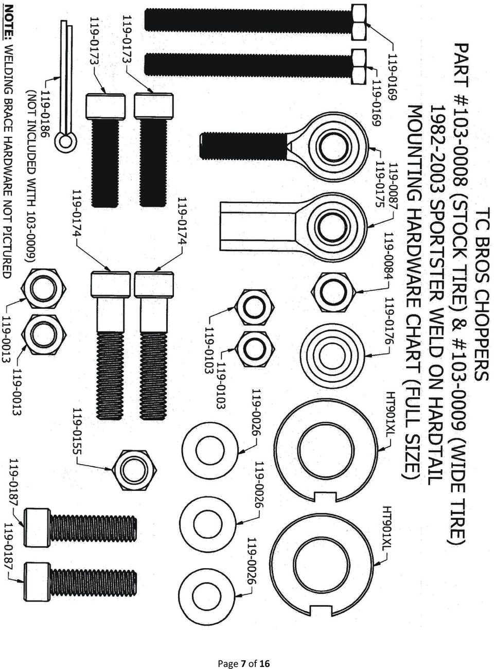
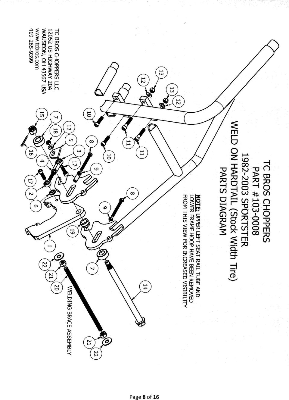
3 6.) Check squareness of cuts using square (See Figure 5) and correct as necessary using grinder, being careful not to make tube any shorter than it is supposed to be, or else you will be left with a much larger gap to fill with weld (may require multiple passes to fill). 7.) Remove paint around all tubes (minimum ½ or 13mm from cut end of tube) to prevent weld contamination (See Figure 6). Sandpaper, wire brush, or abrasive blaster are all effective tools for removing paint. Do not use coarse grinding wheels or sanding disks that may remove significant amounts of steel from tubing, thereby weakening the final welded joint. You only want to remove paint. 8.) Mark center point of hole locations for plug (rosette) welds on bottom sides of stock frame tubing ½ (13mm) from the cut end of the tubes using a center punch and hammer (See Figure 7). Carefully drill 3 holes using a drill bit between 5/16 and 3/8 in diameter (8mm-9.5mm diameter)( See Figure 8). 9.) Gently remove burrs from the inside of the tubes using a file, sanding drum/flap-wheel, or deburring knife. Be sure that paint is removed around the holes to prevent weld contamination (See Figure 9). Page 3 of 16

4 10.) Re-Install Engine into cut, stock front frame half using original engine mounts and hardware. Tighten, but do not fully tighten hardware so that engine can still slide up and down in the stock, slotted engine mounts. 11.) Slide hardtail (backbone slug first, then lower rails) into stock frame until it fully seats against rear portion on engine (transmission) mount. At most, a slight wiggle of the hardtail should be all it takes for the mounts on the hardtail to slide over the dowels on the lower 2 bolts of the rear transmission mount. Place the 4 supplied 3/8 diameter socket head bolts into their respective holes. The 3/8-24 x 1 ¼ long (fine thread, part # ) socket head bolts pass through the holes in the lower welded engine mount of the hardtail and thread into the 2 lower mounting holes of the rear engine mount. The 3/8-16 x 1 ¾ long (coarse thread, part # ) socket head bolts pass through the holes in the upper welded engine mount of the hardtail, then the upper holes of the engine itself, then the 3/8 Flat Washers (part # ), before finally threading into the supplied 3/8-16 Nylock Nuts (part # ). Fully torque all 4 of the supplied socket head bolts to 30ft-lbs (40.7 N m) each. Note: when completing final assembly of the engine after painting frame, apply medium strength threadlocker (Blue Loctite #242 works great) to all fasteners before tightening to manufacturer s recommend torque specification as listed in your service manual. 12.) If you made your cuts correctly, you will most likely notice that the gap at the top backbone tube joint is rather large (See Figure 10). This is totally normal at this point because your engine is most likely fully slid downwards in the slotted mounting holes of the engine mounts, thus leaving your lower engine cases resting on the lower frame tube. You will need to raise the engine by either having a friend lift on the rear of the hardtail or by inserting your stock axle through the slots in the rear axle plates and lifting the frame/engine by placing a small jack underneath the axle (See Figure 11). If your cuts were made correctly, you should be able to lift upward and end up with approximately a 1/8 gap between the ends of all 3 stock frame tubes and all 3 of the hardtail tubes (See Figure 12). This gap is perfectly normal and allows for proper weld penetration into the slug tube in the middle of the joint for the highest final joint strength possible. When it has been determined that the proper joint gap is achieved, and you have visually verified that the lower engine cases are not contacting the lower frame rails, it is time to fully torque all of the fasteners of the original engine mounts to their manufacturer s recommended torque specification (while still lifting the rear of the frame). Page 4 of 16

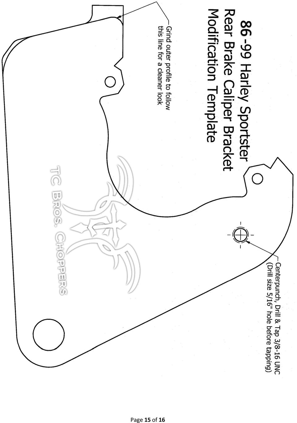
5 13.) Once all of the engine mount fasteners have been tightened, you should be able to discontinue lifting the rear of the frame, and the gaps of the joints will remain the same. After doing a final check to ensure that you have proper gaps, and that the engine cases are not contacting the lower frame rails, it is time to weld the hardtail to your stock frame. You will most likely want to place a piece of protective fire retardant fabric or leather welding blanket between the engine and the frame in order to prevent heat damage and/or weld spatter from sticking to the engine (especially true when MIG welding, see Tools Required for Installation above for proper sized welder). Start by first tack welding the backbone tube, then both lower rails to the hardtail. Then continue welding as much of each joint as possible with engine installed. Remember that the engine is essentially acting as a jig in this instance, so the more welding you can do with the engine installed, the better. Tack welds alone are not sufficient before removing your engine. 14.) After completing as much of the welding as can be done with the engine installed, allow your welds to fully cool, and then remove your engine from the frame. You can now finish all welds 100% around each joint. Do not forget to plug (rosette) weld the 3 holes shut that you drilled earlier. 15.) You may have noticed that the upper seat cross-member tube of our hardtail is only tack welded into place. This was intentionally done like this to allow you to move it if needed for your final seat placement. There are so many size variations of seats, that we really cannot weld it in one place and have it fit everything. This tube MUST BE FULLY WELDED into place before use. To prevent the frame rails of the hardtail from warping inward when welding the seat cross member tube into place, you need to place something in between the axle plates of the hardtail to apply a spreading force against the insides of the axleplates. We include a piece of ½ threaded rod as well as two ½ nuts and two ½ flat washers just for that reason. First you need to assemble them as shown in Figure below, then you will actually need to spread the hardtail approximately ½ wider than it is at finished width so that it will spring back to proper finished width after welding. Proper finished width after welding is 8 ½ (216mm) in between axle plates for part # , and 11 3/16 (284mm) in between axle plates for part # That means that you need to spread the hardtail to 9 (229mm) in between axle plates for part # , and 11-11/16 (297mm) in between axle plates for part # before welding the seat cross member tube to allow the material to spring back to proper finished width previously mentioned. If for some reason your hardtail ends up being narrower than proper finished width after you fully weld your seat cross member tube into place, there is no need to worry because you can use the supplied threaded rod and hardware to spread your hardtail far enough to effectively straighten it so that it returns to proper finished width once the spreader has been removed. Once you have fully welded the seat cross member tube into place, and you have confirmed that your hardtail is at proper finished width between axle plates, installation of the hardtail is complete! NOTES REGARDING REASSEMBLY OF YOUR SPORTSTER AFTER HARDTAIL IS INSTALLED Weld-on Hardtail (Stock Width Wheel/Tire): 1.) The Hardtail is designed to use your stock axle, wheel, wheel spacers, brake components (86-99 are easiest to use), etc. See supplied parts diagram for all that is included with the kit, as well as the sequence that the hardware is designed to be installed. 2.) Your stock belt or chain is too short to fit. This hardtail is stretched 2 longer than the stock wheelbase, so you must use a longer (1-1/8 x 137 tooth HD Part # or # B) belt, or simply convert to chain drive. Chains can be purchased from our web site 3.) The Hardtail is most commonly used in conjunction with a style brake caliper. There are brake anchor hardware components included in the kit to allow easy installation of these model year calipers. There is also a full sized template included to assist with installation of the caliper. The most common method to install the caliper is to drill and tap a 3/8-16 hole in the stock caliper bracket to attach the supplied brake anchor hardware. This requires a 5/16 diameter drill bit and a 3/8-16 UNC Tap (not included). Refer to supplied full sized template to determine hole location. 4.) The style calipers have a large cast portion that wrapped around the stock swingarm. Most customers prefer to remove this for the cleanest look. See figure 13 for the steps of how to remove this if you so desire. Also refer to supplied full sized template for suggested contour. 5.) style calipers can also be installed using TC Bros Part # Anchor Rod Kit (Instructions Included in Kit). Page 5 of 16
.")
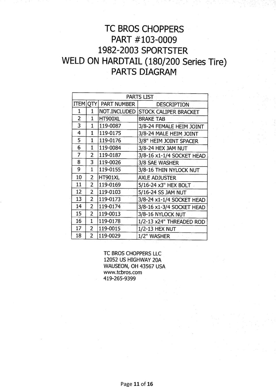
6 6.) style calipers can also be installed, but TC Bros Choppers does not offer an anchor kit at this time. We recommend using style calipers for easiest install as they fit your Stock Sportster wheel and rotor easily. They are readily available on ebay. 7.) It is very important to check for proper chain or belt alignment with a straight edge before use! Weld-on Hardtail (180/200 series Tire/Wheel): 1.) The Hardtail is designed to be used with an aftermarket 180mm or 200mm series tire and a 5.5 Wide Rear Rim with a Big Twin Style hub. The big twin style rear hub has the same 5 bolt pattern as your stock sportster rotor and pulley. 2.) The 5.5 rear wheel and 180mm or 200mm tire is much wider than stock. This requires use of a 1 offset Front Sprocket or Pulley in order to be able to install. We recommend converting to chain drive as the offset pulley components are much more costly than sprockets, and the chain is much narrower than a belt, allowing for greater clearance from the frame rails. 3.) Your stock belt is too short to fit. This hardtail is stretched 2 longer than the stock wheelbase, so you must use a longer (1-1/8 x 137 tooth HD Part # or # B) belt, or simply convert to chain drive. We highly recommend converting belt drive Sportsters to chain drive on the Hardtail for best performance, and most cost savings. 4.) Your stock Axle is too short to fit the hardtail. Your stock spacers also are most likely not the correct length for your aftermarket 5.5 wide wheel. TC Bros Choppers Part # has the correct length stainless steel axle and hardware necessary to install the 5.5 wheel into the hardtail. It is available for purchase on our website 5.) The brake tab (TC Bros #HT900XL) is included, but not welded onto your weld on hardtail like it is on the (stock width) hardtails. This is because of the variety of wheels and brakes that our customers like to use on wide tire builds as opposed to our stock wheel/tire width customers who typically re-use their stock brake components. The tab must be securely welded to the frame before riding in order for the rear brakes to function properly. Please refer to supplied parts diagram for reference as to what is included in the kit. 6.) It is very important to check for proper chain or belt alignment with a straight edge before use! Page 6 of 16
 The 103-0009 Hardtail is designed to be used with an aftermarket 180mm or 200mm series tire and a 5.5 Wide Rear Rim with a 1986-99 Big Twin Style hub.")
7 Page 7 of 16
8 Page 8 of 16
9 Page 9 of 16

10 Page 10 of 16

11 Page 11 of 16
12 Complete Your Sportster With More Parts From TC Bros. Order online 24/7 at: Or Call # TC Bros Holey Battery Box for YTX14AH or 12N14 Series Batteries (Use on # stock width sportster hardtail) # TC Bros Battery Box Mounting Kit for Stock Tire Sportster Hardtail (Use to mount # ) # TC Bros Holey Battery Box for Sportster YTX20 or YB16 Series Batteries (Use ONLY on # /200 series tire sportster hardtail, will not work with stock width.) # TC Bros Battery Box Mounting Kit for 180/200 Series Tire Sportster Hardtail (Use to mount # ) # TC Bros 5 inch Round Pill Style Oil Tank (Use with # heavy duty oil tank mounting kit) # Heavy duty oil tank mounting kit. # TC Bros Spun Fender (works great with stock 130mm tires) # High Strength Stainless Axle Kit for Stock Tire ( ) Sportster Hardtail # High Strength Stainless Axle Kit for 180/200 Series Tire Sportster Hardtail # TC Bros Harley Sportster Hardtail Brake Anchor Rod Kit Page 12 of 16

13 Page 13 of 16

14 See Next Page For Brake Caliper Template. All TC Bros. Hardtails are Proudly Made In USA! See our wide selection of products at Page 14 of 16

15 Page 15 of 16
16 TC BROS. HAS EVERYTHING TO COMPLETE YOUR BIKE! Order online at: Or Call: HUGE SELECTION! IN STOCK! READY TO SHIP! Free Shipping on USA Orders Over $100 *Excludes oversized items and Ebay orders. Page 16 of 16

S&W Race Cars and Components, Inc.
 S&W Race Cars and Components, Inc. 11 Mennonite Church Road Spring City, PA 19475 TECH & INFORMATION: 610-948-7303 ORDERS: 1-800-523-3353 OFFICE FAX: 610-948-7342 E-Z INFO FAX 610-792-1234 CAUTION!!! -
MGB Chrome Bumper Conversion
 MGB Chrome Bumper Conversion Installation Instructions For 1974 1/2-1980 MGB This kit requires cutting, welding, and painting. Professional installation recommended. Note: Every MGB body is slightly different
LG G5 Chassis Brace Gen 5 Camaro THE MOST POWERFUL HEADERS ON THE PLANET Brought to you by LG Motorsports 972-429-1963
 LG G5 Chassis Brace Gen 5 Camaro THE MOST POWERFUL HEADERS ON THE PLANET Brought to you by LG Motorsports 972-429-1963 Thank you for purchasing LG Motorsports products for your Gen 5 Camaro. Parts Inventory:
Thank You For Choosing. INSTALLATION INSTRUCTIONS Portal Gear Hubs Polaris RZR 800. (installation performed on 60 Model) (Right) (Left)
 (Right) (Left)") 740B Clifty Drive Madison, Indiana 47250 812-574-7777 INSTALLATION INSTRUCTIONS Portal Gear Hubs Polaris RZR 800 A (installation performed on 60 Model) Item Description Qty A Rotor 4 B Gear Box, L 2 C
740B Clifty Drive Madison, Indiana 47250 812-574-7777 INSTALLATION INSTRUCTIONS Portal Gear Hubs Polaris RZR 800 A (installation performed on 60 Model) Item Description Qty A Rotor 4 B Gear Box, L 2 C
1. Lay out 2 pieces of 7/8" tubing and mark for bending as shown. Remember that the bend is in the shaded area as shown below in Figure 1.
 MINI BIKE PLANS Page 1 INTRODUCTION Before starting to build your Mini-Bike, be sure that you have all the parts shown on the material list. You will note that tubing has been used in the construction.
STEADYfast Stabilizer Installation Notes Fifth Wheel and Travel Trailers 11/23/13
 STEADYfast Stabilizer Installation Notes Fifth Wheel and Travel Trailers 11/23/13 (See Supplemental Instructions for trailers with heavy duty round footplates and/or Power Leveling Systems) PHONE SUPPORT
Installation Guide for the TJ LCG PRO Suspension System (Low Center of Gravity) Available 4 or 5
 Available 4 or 5") INSTALLATION GUIDE Installation Guide for the TJ LCG PRO Suspension System (Low Center of Gravity) Available 4 or 5 Take every precaution to make this installation a safe procedure. Make safety the number
INSTALLATION GUIDE Installation Guide for the TJ LCG PRO Suspension System (Low Center of Gravity) Available 4 or 5 Take every precaution to make this installation a safe procedure. Make safety the number
FRONT BUMPER INSTALLATION INSTRUCTIONS 2007-2011 DODGE / MERCEDES SPRINTER
 Aluminess Products Inc 9402 Wheatlands Ct. #A Santee, CA 92071 619-449-9930 FRONT BUMPER INSTALLATION INSTRUCTIONS 2007-2011 DODGE / MERCEDES SPRINTER Please read before beginning Stainless steel hardware
Thank You For Choosing. INSTALLATION INSTRUCTIONS Portal Gear Hubs Polaris RZR XP 900 Crew. (Right) (Left)
 (Left)") 740B Clifty Drive Madison, Indiana 47250 812-574-7777 INSTALLATION INSTRUCTIONS Portal Gear Hubs Polaris RZR XP 900 Crew A Item Description Qty A Rotor 4 B Gear Box, L 2 C Gear Box, R 2 D Gasket 4 E Cap
740B Clifty Drive Madison, Indiana 47250 812-574-7777 INSTALLATION INSTRUCTIONS Portal Gear Hubs Polaris RZR XP 900 Crew A Item Description Qty A Rotor 4 B Gear Box, L 2 C Gear Box, R 2 D Gasket 4 E Cap
BUILDINGA 1/10 SCALE FLATBED TRAILER
 VOLUME 1, ISSUE 1 BUILDINGA 1/10 SCALE FLATBED TRAILER BUILT, DESIGNED & WRITTEN BY NATHAN MYERS MATERIALS: FEATURES: While the design was kept simple to allow anyone to be able to build their own trailer,
LIFT-505. BMF Lift Kit. Yamaha Drive Gas or Electric. Installation Instructions
 LIFT-505 BMF Lift Kit Yamaha Drive Gas or Electric Installation Instructions Contents of LIFT-505 Yamaha Drive BMF Lift Kit: a (1 ea.) BMF A-Arm Assembly b (1 ea.) Driver Side Shock Tower c (1 ea.) Passenger
ReadyLift (Part# 66-5075) Strut Extension, Installation Instructions Toyota Tundra New Body Style 2WD & 4WD
 Strut Extension, Installation Instructions Toyota Tundra New Body Style 2WD & 4WD") SAFETY WARNING: recommends this system be installed by a professional technician. In addition to these instructions, professional knowledge of disassembly/ reassembly procedures and post installation checks
SAFETY WARNING: recommends this system be installed by a professional technician. In addition to these instructions, professional knowledge of disassembly/ reassembly procedures and post installation checks
Slide the new steering column shaft through the steering column from the driver compartment.
 Slide the new steering column shaft through the steering column from the driver compartment. Push the column shaft through the steering column until the machined end is out past the column lower bushing.
Installation Instructions GOOSENECK MOUNTING KIT Chevrolet/GMC 1500/2500/3500 All except 4-door Crew-Cab
 GOOSENECK MOUNTING KIT Equipment Required: Fastener Kit: F Wrenches: 3/4, 7/8, 15/16 Drill Bits: 1/4 Other Tools: Drill WARNING: Under no circumstances do we recommend exceeding the towing vehicle manufacturers
INSTALLATION INSTRUCTIONS for Bifold Doors (JII103)
") Thank you for selecting JELD-WEN products. Attached are JELD-WEN s recommended installation instructions for premium composite, hollow and solid core molded Bifold Doors. Bifolds are designed for fast
Thank you for selecting JELD-WEN products. Attached are JELD-WEN s recommended installation instructions for premium composite, hollow and solid core molded Bifold Doors. Bifolds are designed for fast
R O A D M A S T E R, I N C.
 R O A D M A S T E R, I N C. ROADMASTER, Inc. 6110 NE 127th Ave. Vancouver, WA 98682 6 13 11 MOUNTING BRACKET KIT Cable Tab 14 12 7 15 9 Cable Tab 360-896-0407 fax 360-735-9300 www.roadmasterinc.com ITEM
ASSEMBLY DIAGRAM AND ASSEMBLY REFERENCE ULTIMA OLD SCHOOL 2 EVO & TC BELT DRIVE UNITS
 ASSEMBLY DIAGRAM AND ASSEMBLY REFERENCE ULTIMA OLD SCHOOL 2 EVO & TC BELT DRIVE UNITS BELT DRIVE ASSEMBLIES Part# 58-850 2 Old School Belt Drive Assembly - Polished Part# 58-851 2 Old School Belt Drive
SLACK PERFORMANCE KARTS
 SLACK PERFORMANCE KARTS SET UP GUIDE Thank you for purchasing a 2013 Slack Axiom Chassis. Performance Mfg. strives to provide you with the very best chassis and components on the market today. Your satisfaction
TRANS-05, Torque Tube Removal, Rebuilding, and Installation
 TRANS-05, Torque Tube Removal, Rebuilding, and Installation Tools Metric Wrench Set Metric Socket Set Jack Stands (6 minimum) Floor Jack 8mm Cheesehead socket (also referred to as 12 point internal socket
16 April 2012 1032011-F 1994-2002 Dodge Adjustable Track bar with Relocation Bracket 1
 16 April 2012 1032011-F 1994-2002 Dodge Adjustable Track bar with Relocation Bracket 1 BD Adjustable Track Bar w/bracket Dodge 2500-3500 4WD Models 1994-2002 Dodge 1500 4WD Model 1994-2001 P/N# 1032011-F
DiscPlus DX195 and DX225 Air Disc Brakes
 Revised 11-04 Technical Bulletin Revised 1 Technical 11-04 Bulletin DiscPlus DX195 and DX225 Air Disc Brakes Inspection, Installation and Diagnostics Air Disc Brake Inspection Intervals and Procedures
Tooling List 17mm Socket 17mm Wrench 24mm Wrench 26mm Wrench 3/8 Drive Ratchet Torque Wrench
 Thank you for purchasing the CorkSport Rear Adjustable Camber Arms. By replacing your OEM camber arms with the CorkSport Adjustable Camber Arms, you will be able to dial in your suspension with +/- 5 degrees
INSTALLATION INSTRUCTIONS COMPETITION SERIES COILOVER SUSPENSION SYSTEM 03+ Scion xb
 INSTALLATION INSTRUCTIONS COMPETITION SERIES COILOVER SUSPENSION SYSTEM 03+ Scion xb NOTE: Progress Technology products should only be installed by a qualified licensed mechanic experienced in the installation
CorkSport Mazdaspeed 6 Rear Sway Bar 2006-2007 Mazdaspeed 6
 CorkSport Mazdaspeed 6 Rear Sway Bar 2006-2007 Mazdaspeed 6 Pre-Installation Notes: The CorkSport Rear Sway Bar is a great addition to improving the handling performance to the Mazdaspeed 6. It will minimize
INSTALLATION INSTRUCTIONS. 6111 Air Spring Kit 2011+ Ford F250/F-350 Single Wheel 2WD 2011+ Ford F350 Dually 2WD IMPORTANT NOTES
 INSTALLATION INSTRUCTIONS 6111 Air Spring Kit 2011+ Ford F250/F-350 Single Wheel 2WD 2011+ Ford F350 Dually 2WD Thank you for purchasing a quality Hellwig Product. PLEASE READ THIS INSTRUCTION SHEET COMPLETELY
READ AND UNDERSTAND ALL INSTRUCTIONS AND WARNINGS PRIOR TO INSTALLATION OF SYSTEM AND OPERATION OF VEHICLE.
 491 W. Garfield Ave., Coldwater, MI 49036 Phone: 517-279-2135 Web/live chat: www.bds-suspension.com E-mail: tech-bds@sporttruckusainc.com Product: GM Leaf Spring READ AND UNDERSTAND ALL INSTRUCTIONS AND
»Product» Safety Warning
 C1200 Installation Instructions 2007-2016 Chevy/GM 1500 2/4wd 2" Strut Spacer Lift Read and understand all instructions and warnings prior to installation of product and operation of vehicle. Zone Offroad
R O A D M A S T E R, I N C.
 R O A D M A S T E R, I N C. MOUNTING BRACKET KIT 12 3 6 9 5 11 ITEM QTY NAME MATERIAL 1...4...1/2" x 1 1/2" BOLT... 350095-00 2...4...1/2" x 1 1/2" CARRIAGE BOLT... 350362-00 3...8...1/2" NUT... 350258-00
Auto-belay Cable Replacement Process
 Auto-belay Cable Replacement Process Version 2.00 WARNING: The air pressure in the auto-belay system is what causes the cable to be retracted when releasing the cable or climbing the wall with the cable
INSTALLATION INSTRUCTIONS. 6108 Air Spring Kit 2011+ Ford F250 Single Wheel 4WD 2011+ Ford F350 Dually 4WD (2011 F350 Single Wheel 4WD use p/n 6113)
") INSTALLATION INSTRUCTIONS 6108 Air Spring Kit 2011+ Ford F250 Single Wheel 4WD 2011+ Ford F350 Dually 4WD (2011 F350 Single Wheel 4WD use p/n 6113) Thank you for purchasing a quality Hellwig Product. PLEASE
INSTALLATION INSTRUCTIONS 6108 Air Spring Kit 2011+ Ford F250 Single Wheel 4WD 2011+ Ford F350 Dually 4WD (2011 F350 Single Wheel 4WD use p/n 6113) Thank you for purchasing a quality Hellwig Product. PLEASE
Owner s Manual Read and keep this manual. Patents World Wide
 Owner s Manual Read and keep this manual. Patents World Wide S & S Industries, Inc., Sarasota, FL, USA www.trail-gator.com Copyright 2008 All Rights Reserved The following manual is provided to assist
2011-14 F250 6 RADIUS ARM KIT
 92154000 Thank you for choosing Rough Country for your suspension needs. 2011-14 F250 6 RADIUS ARM KIT Rough Country recommends a certified technician installs this system. In addition to these instructions,
88-98 Chevy / GMC Fullsize 4WD 6-Lug 2"- 2 1/2" Suspension Lift Installation Instructions
 88-98 Chevy / GMC Fullsize 4WD 6-Lug 2"- 2 1/2" Suspension Lift Installation Instructions Safety Glasses Metric / Standard Wrenches & Sockets Floor Jack Jack Stands Hack Saw Ball Joint Seperator Measuring
Verify caster, camber and toe-in are correct before proceeding.
 If rotating the tie rod end 360 degrees changes the toe-in too much, use the rack tie rod to make smaller adjustments. Put the tie rod end in the steering arm and snug the castle nut before adjusting.
INSTRUCTIONS THOROUGHLY BEFORE BEGINNING***************
 Bill of Materials: RAC0012 Green Wing Aerodynamic Skirt Kit Item Part Number Description Quantity 1 RMC0218 Gen 2 Trailer Skirt Roadside 1 2 RMC0219 Gen 2 Trailer Skirt Curbside 1 3 RMC0041 Trailer Skirt
Little British Car Co.
 Little British Car Co. 29311 Aranel, Farmington Hills, MI 48334-2815, USA Tel: 248 489 0022 or 800 637 9640 Fax: 248 489 9665 On the web at: www.lbcarco.com E-mail: LBCarco@LBCarCo.com MGB Tube Rear Shock
92-00 Civic/ 94-01 Integra/ 93-97 Del Sol/ 92-95 CRX Rear Kit Part No. 75540
 92-00 Civic/ 94-01 Integra/ 93-97 Del Sol/ 92-95 CRX Rear Kit Part No. 75540 www.airliftperformance.com MN-514 (06409) NPR 4762 Please read these instructions completely before proceeding with installation
MKV Golf GTI Rear Brake Service - Replace Pads and Rotors
 Page 1 Installation Procedures MKV Golf GTI Rear Brake Service - This tutorial is provided as a courtesy by ECS Tuning. Proper service and repair procedures are vital to the safe, reliable operation of
It's large enough to handle most welding job shop projects, yet small enough to make it a worth while home-workshop tool
 It's large enough to handle most welding job shop projects, yet small enough to make it a worth while home-workshop tool H Craft Print Project No. 272 ERE'S a metal bender that will enable you to bend
FOR ANY QUESTIONS, PLEASE CALL US @ 727.347.9915 M-F 8:00a.m.-8:00p.m. EST. REAR BRAKES 1 AEROSPACE COMPONENTS 727.347.9915
 REAR BRAKES 1 AEROSPACE COMPONENTS 727.347.9915 REAR BRAKES Before getting started, remove all stock braking components. Pre-assembly of parts: Clean the bolts and the threads in the hat with acetone.
6 inch A-Arm Lift Kit WARNING: 16-018/16-019. installation instructions. will fit CLUB CAR DS. included:
 Revised May 205 6-08/6-09 6 inch A-Arm Lift Kit will fit CLUB CAR DS installation instructions included: Rear Lift Blocks Main Suspension Assembly Spindles A-Arms Rear Shock Mounting Plates U-Bolts WARNING:
Installation Guide 2010 BMW S1000RR Full Exhaust System
 Installation Guide 2010 BMW S1000RR Full Exhaust System!! THIS PRODUCT IS DESIGNED FOR USE IN CLOSED COURSE RACING AND IS NOT INTENDED FOR HIGHWAY USE!! Congratulations on the purchase of your new TaylorMade
Street-Lynx. Reilly MotorSports, Inc. Installation Manual
 Street-Lynx By Reilly MotorSports, Inc. Installation Manual 1 1- Begin by removing your original rear suspension disconnect your brake lines, E-brake cables, and remove the driveshaft. To prevent fire
Ford F-250 / 350 2-1/2 Coil Kit. Ford F-250, F350 2011-2015. Part#: 013255
 Part#: 013255 Ford F-250 / 350 2-1/2 Coil Kit Ford F-250, F350 2011-2015 Rev.040815 491 W. Garfield Ave., Coldwater, MI 49036. Phone: 517-279-2135 Web/live chat: www.bds-suspension.com. E-mail: tech@bds-suspension.com
R O A D M A S T E R, I N C.
 R O A D M A S T E R, I N C. ROADMASTER, Inc. 6110 NE 127th Ave. Vancouver, WA 98682 12 10 3 11 4 5 13 7 8 360-896-0407 fax 360-735-9300 www.roadmasterinc.com ITEM QTY NAME MATERIAL 1... 4...1/2 x 1 1/2
2. This is a close up of a typical area where the rocker is rusted out leaving holes under where the rocker moulding would be..
 ROCKER PANELS 55,56,57 CHEVY REPLACEMENT Do not throw away any pieces when you first remove them. There are many supports that are not reproduced and will need to be used again. When disassembling try
Wheel Stud Conversion Kit Installation Instructions
 Wheel Stud Conversion Kit Installation Instructions Proper service and repair procedures are vital to the safe, reliable operation of all motor vehicles as well as the personal safety of those performing
Build Your Own Solar Car Teach build learn renewable Energy! Page 1 of 1
 Solar Car Teach build learn renewable Energy! Page 1 of 1 Background Not only is the sun a source of heat and light, it s a source of electricity too! Solar cells, also called photovoltaic cells, are used
TABLE OF CONTENTS. Section 1 - Assembling your new pit bike.
 Orion Pit Bike Sales Owners Manual (All information and content is the property of Orion Pit Bike Sales. Any attempt to copy or resell is a direct violation of our copyright. All violators will be prosecuted)
R O A D M A S T E R, I N C.
 R O A D M A S T E R, I N C. MOUNTING BRACKET KIT 14 8 7 4 13 5 6 ITEM QTY NAME MATERIAL 1...6...1/2" x 2 1/2" BOLT... 350099-00 2...2...1/2" x 1 1/2" BOLT... 350095-00 3...8...1/2" LOCK WASHER... 350309-00
Rebuild Instructions for 70001 and 70010 Transmission
 Rebuild Instructions for 70001 and 70010 Transmission Brinn, Incorporated 1615 Tech Drive Bay City, MI 48706 Telephone 989.686.8920 Fax 989.686.6520 www.brinninc.com Notice Read all instructions before
Fabricating a chassis from clad PCB board material
 Fabricating a chassis from clad PCB board material How many times have you started a project and the finished appearance is based on what box you had laying around, rather than what you would like to have?
WARNING TO END USER, INSTALLER AND SELLER OF THIS PART!
 WARNING TO END USER, INSTALLER AND SELLER OF THIS PART! By installing this part you are accepting full responsibility and liability for proper wheel and tire fitment after installation. It is the installer
INTENSE Street/Strip Shift Pak for 4T65E and 4T65E-HD Transaxles SAC 9.6.05 Visit us at www.intense-racing.com!
 INTENSE Street/Strip Shift Pak for 4T65E and 4T65E-HD Transaxles SAC 9.6.05 Visit us at www.intense-racing.com! Applications: 1998-current Grand Prix GT 1998-current Monte Carlo 1998-current other applications
Tools Required: Sawzall, hack saw, or small body saw, drill, ¼ drill bit, ¾ hole saw, tape measure, silicone or epoxy, & 7/16 socket.
 When installing a one-piece window kit, it is best to do it as early as possible in the restoration process. This will allow for minimal repairs if need be. Kit Contents: Glass - 2 pcs Felt channels 2
www.cornholesupplies.com
 www.cornholesupplies.com How To Build Regulation Cornhole Boards Home of the Original Cornhole Bags and Boards Supply List: 1-4' X 8' Piece of Plywood (pre sanded) 4-2" X 4" X 8' Studs (2 by 4s make sure
SUSP-06, Torsion Bars - Removing, Replacing, and Indexing
 Introduction SUSP-06, Torsion Bars - Removing, Replacing, and Indexing Replacing the torsion bar on a 944 is not all that difficult. However, reindexing the torsion after completion is a pain and can be
DIY CABINET REFACING INSTALLATION GUIDE
 DIY CABINET REFACING INSTALLATION GUIDE CABINET REFACING INSTALLATION Are you ready to reface your outdated cabinets? This guide will show you how to install your new Facelifters Cabinet Refacing Products
R O A D M A S T E R, I N C.
 R O A D M A S T E R, I N C. 11 10 20 12 4 18 19 1 2 13 16 ITEM QTY NAME MATERIAL 1...2... 1/2" x 3 1/2" BOLT... 350103-00 2...2... 1/2" x 2" BOLT... 350097-00 3...6... 1/2" x 1 1/2" BOLT... 350095-00 4...2...
MUSTANG II IFS COMPLETE PARTS PACKAGE
 MUSTANG II IFS COMPLETE PARTS PACKAGE Your Southern Rods & Parts Mustang II IFS Parts Package contains the following items: 1 pr) Upper Control Arms (2023) 1) Upper Arm Bolt Kit (MP-001-A) 1 pr) Lower
OWNER S MANUAL Table Tennis Table Patent Pending
 OWNER S MANUAL Table Tennis Table Patent Pending Be sure to write your model number and serial number here for future reference. You can find these numbers printed on the bottom of the table. MODEL # T8179
INSTRUCTIONS: LocknCharge Laptop Carts
 INSTRUCTIONS: LocknCharge Laptop Carts www.lockncharge.com Extra Tools required: Hammer, Philips head screwdriver, medium adjustable spanner. (Allen key supplied) (Panel colours for illustration purposes
2014-2015 GM 1500 Pick-Up 4WD 4" Suspension Lift Installation Instructions
 2014-2015 GM 1500 Pick-Up 4WD 4" Suspension Lift Installation Instructions www.skyjacker.com Required Tool List: * Safety Glasses * Metric / Standard Wrenches & Sockets * Allen Wrenches * Floor Jack *
SELF-STEERING AXLE TABLE OF CONTENTS
 SELF-STEERING AXLE TABLE OF CONTENTS Section 1 - Introduction Section 2 - Pre-Installation Check List Section 3 - Ride Height Adjustments Section 4 - Suspension Mount Section 5 - Axle Mount Section 6 -
Understanding Wheel Offset and Backspacing
 Understanding Offset and Backspacing Proper service and repair procedures are vital to the safe, reliable operation of all motor vehicles as well as the personal safety of those performing the repairs.
Check for deteriorated, shifting or missing tie-down pads. Replace if needed.
 C C 0 5 C H A S S I S F R A M E Chassis Frame Overview The Blue Bird Vision s chassis frame consists of two main C-channel rails which run the entire length of the bus, and several different kinds of cross
Front axle components, overview
 just a test. Front axle components, overview 40-1 General Information Load bearing components and parts of the suspension must not be welded or straightened. Vehicles without drive axle must not be moved,
R O A D M A S T E R, I N C.
 R O A D M A S T E R, I N C. ROADMASTER, Inc. 6110 NE 127th Ave. Vancouver, WA 98682 8 7 1 6 15 28 1 2 "± 1 2 " MOUNTING BRACKET KIT 3 2 10 14 4 5 9 360-896-0407 fax 360-735-9300 www.roadmasterinc.com Item
READ THE INSTRUCTIONS SEVERAL TIMES BEFORE STARTING ASSEMBLY
 1954-87 CHEV BED INSTRUCTIONS (Revised Nov 2002) Thank you and congratulations on your purchase of the finest Street Rod Pickup Bed on the market today. The following instructions should help you assemble
Make sure all tubes are installed to your satisfaction BEFORE finish welding!!
 INTRODUCTION: This S&W Roll Bar or Roll Cage performs both a safety and performance function. As a safety device, the main hoop of the cage protects the driver from impact. The rear braces and side bars
Competition 4 & 6 suspension Lift Toyota Landcruiser & nissan patrol
 Competition 4 & 6 suspension Lift Toyota Landcruiser & nissan patrol Competition suspension Product Guidelines Guidelines for sale and recommendation of 4 (100mm) and 6 (150mm) Lifts for Toyota Landcruiser
AM/FM ANTENNA RELOCATION KIT
 -J0 REV. 008-09-0 AM/FM ANTENNA RELOCATION KIT GENERAL Kit Number 766-09 Models This kit is used to relocate a fender-mounted AM/FM antenna to a Detachable Tour-Pak on specific model motorcycles. For model
R O A D M A S T E R, I N C.
 R O A D M A S T E R, I N C. ROADMASTER, Inc. 6110 NE 127th Ave. Vancouver, WA 98682 4 MOUNTING BRACKET KIT 1 2 3 360-896-0407 fax 360-735-9300 www.roadmasterinc.com ITEM QTY NAME PART # 1...2... #10 x
COOPER S PULLEY UPGRADE KIT INSTALLATION INSTRUCTIONS PART NUMBER NME5011
 COOPER S PULLEY UPGRADE KIT INSTALLATION INSTRUCTIONS PART NUMBER NME5011 Below are instructions for the Mini Mania Pulley Upgrade Kit, Part Number NME5011. Please take all necessary precautions for working
R O A D M A S T E R, I N C.
 R O A D M A S T E R, I N C. 11 7 6 1 2 10 13 8 ITEM QTY NAME PART # 1...2...1/2 x 5 1/2 BOLT...350108-00 2...4...1/2 x 1 3/4 BOLT...350096-00 3...6...1/2 LOCK WASHER...350309-00 4...6...1/2 HEX NUT...350258-00
R O A D M A S T E R, I N C.
 R O A D M A S T E R, I N C. ROADMASTER, Inc. 6110 NE 127th Ave. Vancouver, WA 98682 16 6 18 Cable Tab 13 15 8 10 2 Cable Tab 1 11 9 17 14 360-896-0407 fax 360-735-9300 www.roadmasterinc.com ITEM QTY NAME
4BT A/C Bracket Directions
 4BT A/C Bracket Directions This kit will be broken into smaller kits for ease of installation and recognition of hardware. Tools needed for install; 3/8 Ratchet 1/2 wrench 1/2 socket 9/16 wrench 9/16 socket
SPRITE and BIGFOOT DESKTOP CNC MACHINE KIT ASSEMBLY INSTRUCTIONS
 SPRITE and BIGFOOT DESKTOP CNC MACHINE KIT ASSEMBLY INSTRUCTIONS README FIRST: Thank you for purchasing your MyDIYCNC Desktop CNC Machine Kit. We hope this versatile and innovative machine brings you many
R O A D M A S T E R, I N C.
 R O A D M A S T E R, I N C. 6 28 1 2 "ā 1 2 " 4 8 ITEM QTY NAME PART # 1...4...1/2 x 1 1/4 BOLTS... 350094-00 2...4...1/2 LOCK WASHER... 350309-00 3...4...1/2 HEX NUT... 350258-00 4...2...SPACER PLATE...
Installation manual. 1.75 front leveling kit. 2011 Dodge Durango 2011-2014 Jeep Grand Cherokee. Part # 42006. Part # 42006
 Installation manual 1.75 front leveling kit 2011 Dodge Durango 2011-2014 Jeep Grand Cherokee Part # 42006 sj02282011rev.01 Part # 42006 2011-2014 Dodge Durango 2011 Jeep Grand Cherokee 1.75 front leveling
1958-64 WINDOW CHANNEL, WEATHERSTRIP & WHISKER STRIP REPLACEMENT FOR 2-DOOR SEDANS
 By Denny Williams Photos by Denny Williams 1958-64 WINDOW CHANNEL, WEATHERSTRIP & WHISKER STRIP REPLACEMENT FOR 2-DOOR SEDANS Denny Williams - Technical Writer Denny is first and foremost a dyed-in-thewool
SCION tc 2005-2008 COIL OVER SUSPENSION Preparation
 SCION tc 2005-2008 COIL OVER SUSPENSION Preparation Part Number: PTR11-21070 NOTE: Part number of this accessory may not be the same as the part number shown. Kit Contents: Item # Quantity Reqd. Description
BUGGY SETUP GUIDE. Volume GOKARTSUSA GY6 150, CN250. Buggy Setup Guide
 BUGGY SETUP GUIDE Volume 1 GOKARTSUSA GY6 150, CN250 Buggy Setup Guide GY6 150, CN250 DUNE BUGGY Buggy Setup Guide GOKARTSUSA.COM 2000 Highway 50 S. Lake Tahoe, CA 96150 Phone 800.603.1437 2 Table of Contents
Installation Manual. Toilet Partitions, Dressing Compartments & Shower Stalls
 Installation Manual Toilet Partitions, Dressing Compartments & Shower Stalls Metpar Corp 95 State Street, Westbury, New York, USA, 11590 Tel: 516-333-2600 Fax: 516-333-2618 Internet: http://www.metpar.com
JK 2.5 Spring Lift Part # 1251000-1251002 # 1351000-1351002 # 1352000-1352002
 TeraFlex, Inc. 5241 South Commerce Dr. Murray, Utah 84107 Phone/801.288.2585 Fax/801.713.2313 www.teraflex.biz Rev. 2 December 2010 TT PRODUCT INSTALLATION GUIDE JK 2.5 Spring Lift Part # 1251000-1251002
ADVANCE ADAPTERS INC. Fixed Yoke kit (S.Y.E. Kit)
") ADVANCE ADAPTERS INC. Fixed Yoke kit (S.Y.E. Kit) Instruction Sheet P/N: 50-7905 & 50-7906 KIT CONSISTS OF: No. Qty Part No. Description 1. 1 51-7906 TAILHOUSING, DIECAST 2. 1 52-7905 SHAFT, MAIN OUTPUT
ADVANCE ADAPTERS INC. Fixed Yoke kit (S.Y.E. Kit) Instruction Sheet P/N: 50-7905 & 50-7906 KIT CONSISTS OF: No. Qty Part No. Description 1. 1 51-7906 TAILHOUSING, DIECAST 2. 1 52-7905 SHAFT, MAIN OUTPUT
1.8 CRANKSHAFT OIL SEALS
 SERIES 60 SERVICE MANUAL 1.8 CRANKSHAFT OIL SEALS An oil seal is fitted between each end of the crankshaft and the bores of the flywheel housing and gear case cover to retain the lubricating oil in the
Customer Service 800.780.8889 or visit us online at smithnoble.com. Wood Shutters. Step by Step Installation. Troubleshooting Tips
 reflect your style TM Customer Service 800.780.8889 or visit us online at smithnoble.com Wood Shutters Step by Step Installation Troubleshooting Tips Easy Care Instructions STEP 1 Your New Shutter Thank
BUILD A TABLETOP LOOM
 BUILD A TABLETOP LOOM From 1" x 2" stock (actual 3/4" x 1"1/2) cut: 4 pieces 15" long 4 pieces 5"1/2 long Use the above to make 2 frames for the front and back of the loom. From 1" x 4" stock (actual 3/4"
Go-kart for little race-drivers
 Go-kart for little race-drivers Drill and drive. Go-kart What it lacks in speed, it more than makes up for in fun: the go-kart will excite little race-drivers. 1 Introduction It s only a go-kart, but it
STEERING HANDLEBAR/FRONT WHEEL/ FRONT SHOCK ABSORBER
 14 14 STEERING HANDLEBAR/FRONT WHEEL/ SCHEMATIC DRAWING ------------------------------------------------- 14-1 SERVICE INFORMATION------------------------------------------------ 14-2 TROUBLESHOOTING-----------------------------------------------------
Corvette Hub/Bearing Adapter Installation Manual 4th-Gen F-body
 Corvette Hub/Bearing Adapter Installation Manual 4th-Gen F-body This manual covers the installation of our Corvette hub adapter, used with 98+ (LS1 style) Camaro and Firebird spindles. The adapter will
Gripper Kit for the Boe-Bot Robot (#28202)
") 599 Menlo Drive, Suite 100 Rocklin, California 95765, USA Office: (916) 624-8333 Fax: (916) 624-8003 General: info@parallax.com Technical: support@parallax.com Web Site: www.parallax.com Educational: www.stampsinclass.com
599 Menlo Drive, Suite 100 Rocklin, California 95765, USA Office: (916) 624-8333 Fax: (916) 624-8003 General: info@parallax.com Technical: support@parallax.com Web Site: www.parallax.com Educational: www.stampsinclass.com
Lathe Milling Attachment
 Lathe Milling Attachment By L C. MASON BY CLEVERLY stacking cold-rolled flat stock together, T-slots and slide for this lathe milling attachment are made without costly machinery. In fact, only two tools,
CAM-03, Camshaft Assembly Oil Seal Replacement
 CAM-03, Camshaft Assembly Oil Seal Replacement Tools Jack stands Floor Jack Metric Socket set Metric Wrench set Porsche Timing Belt Tension tool (P9201) Flywheel Lock (P9206) Balance Shaft Pin Spanner
How to Build Your Own CornHole Game
 How to Build Your Own CornHole Game DIMENSIONS Here is a diagram with the basic measurements for the Cornhole board game. SUPPLIES 1/2 thick sheet of plywood one 4 x4 or two 2 x4 s 8 long 2 4 s (4) 4 1/2
ZAPPY 3 OWNER S MANUAL. Read this manual completely before riding your Electric ZAPPY 3.
 ZAPPY 3 OWNER S MANUAL Read this manual completely before riding your Electric ZAPPY 3. TECHNICAL INFORMATION Model No. : ZAPPY 3 Product size Type of motor Motor power Battery type Battery Charger Charging
Step 1. Item 6. Item 1
 Voltage Regulators QD3/T350 Motor Replacement Kit Kit Number 57A63675100B Service Information S225-50-35 Contents General..................................... 1 Parts Supplied...............................
2002 2005 Mini Cooper S Grille Install Instructions
 2002 2005 Mini Cooper S Grille Install Instructions Lower Front Grille BEFORE AFTER Package Contents 1 perforated grille (Stiletto, RAZR, or Monster) 6 Zip Tie Mounting Pads 1 is for the temp. sensor 5
Important: Please read these instructions carefully and completely before starting the installation. TITAN Fuel Tanks
 TITAN pt. no.: 03 0000 0120 Important: Please read these instructions carefully and completely before starting the installation. TITAN Fuel Tanks INSTALLATION INSTRUCTIONS G e n e r a t i o n V Extended