Chapter 8. Flexural Analysis of T-Beams
|
|
|
- Rosalyn Holt
- 9 years ago
- Views:
Transcription
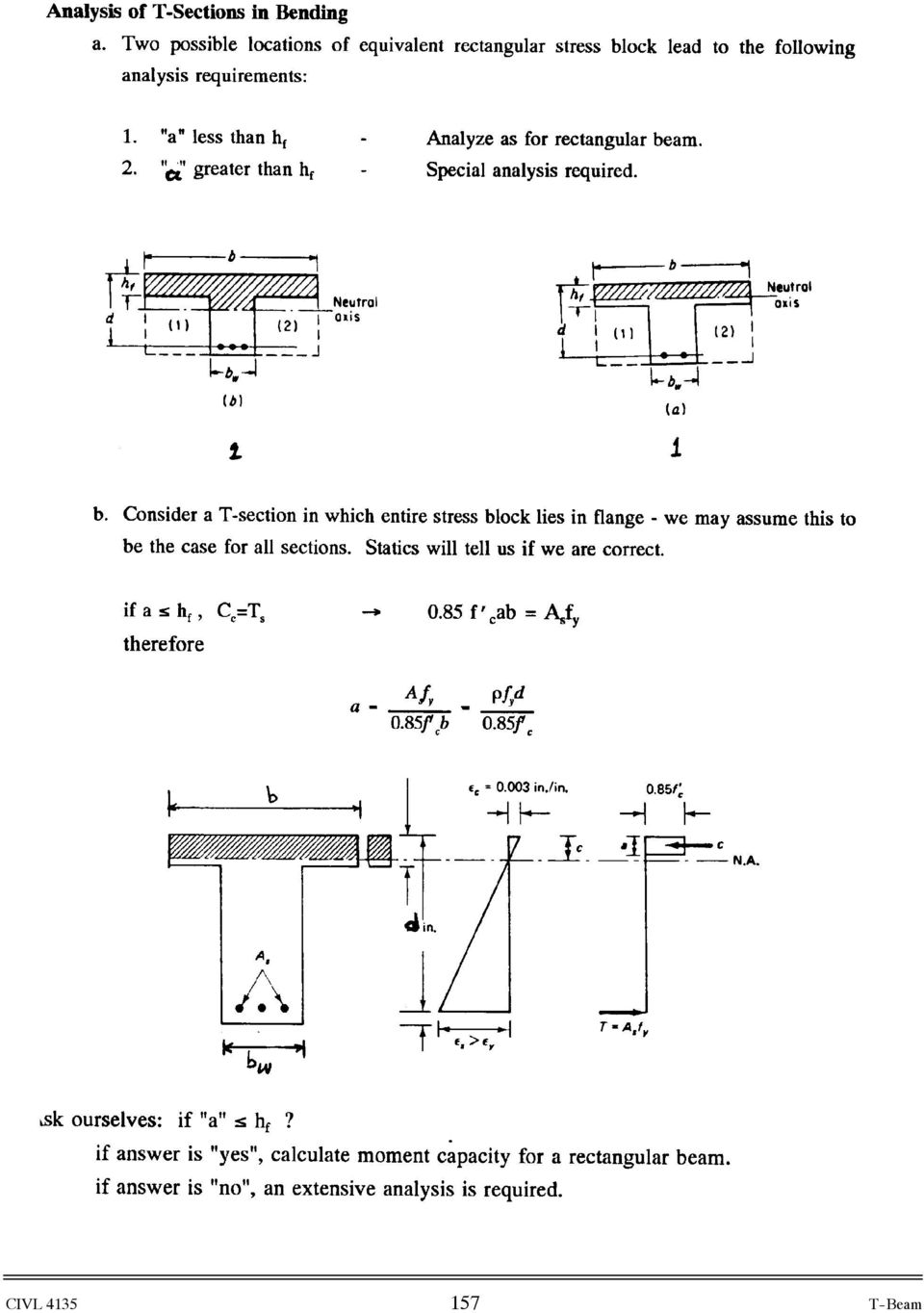
1 Chapter 8. Flexural Analysis of T-s 8.1. Reading Assignments Text Chapter 3.7; ACI 318, Section Occurrence and Configuration of T-s Common construction type.- used in conjunction with either on-way or two-way slabs. Sections consists of the flange and web or stem; the slab forms the beam flange, while the part of the beam projecting below the slab forms is what is called web or stem. (a) one-way slab (b) two-way slab 8.3. Concepts of the effective width, Code allowable values In reality the maximum compression stress in T-section varies with distance from section Web. Real max, Longitudinal compression sress Simplified equivalent width, stress 156
 one-way slab (b) two-way slab 8.3.")
2 157
3 Code allows the following maximum effective widths: Symmetrical ACI318, Section b 1) b span 4 2) b Flange on one side only (Spandrel ) ACI318, Section ) b clear distance between beams b 1) b span 12 2) b 6 3) b 1 2 clear distance to next web Isolated T- ACI318, Section b 1) b 4 2) 2 158
 b 2 1 2 clear distance between beams b 1) b span 12 2) b 6 3) b 1 2 clear")
4 8.4. Analysis of T-s - ( a > ) Consider the total section in two parts: 1) Flange overhangs and corresponding steel; 2) Stem and corresponding steel; b 0.85f c C c a T s =A s f y = + A sf Case I A s- A sf Case II For equilibrium we have: Case I: A sf f y = 0.85f c (b ) (8.1) or A sf = 0.85f c (b ) f y (8.2) Case II: Solve for a : (A s A sf ) f y = 0.85f c a (8.3) a = (A s A sf ) f y 0.85f c (8.4) and nominal moment capacity will be: M n = A sf f y (d 2 ) + (A s A sf ) f y (d a 2 ) (8.5) 159
 a = (A s A sf ) f y 0.85f c (8.")
5 8.5. Balanced Condition for T-s See Commentary page 48 of ACI (old code). b Áu = c b a b 0.85f c C c h d A b s Á y d-c T s =A s b f y From geometry: c b = Á u Á u + Á y d = 87, , f y d (8.6) 160

6 8.6. Example.- Analysis of T-s in Bending: 40 =4 Á u = f c c C c 20.5 A s = 6.88 in 2 Á y d-c T s =A s f y 10 Find the nominal moment capacity of the beam given above: f c = 2, 400 psi f y = 50, 000 psi Solution: Check to see if a T-beam analysis is required: Assume a< a = A s f y 0.85f c b = = 4.22 in Since 4.22 in > 4.00 in, a T-beam analysis is required. First find the reinforcement area to balance flanges (A sf =?) A sf = 0.85 f c (b b f w ) = (40 10) 4 = 4.90 in2 y 50 A s A sf = = 1.98 in 2 Solve for a 0.85f c a = (A s A sf )f y a = (A s A sf )f y = f c = 4.86 in > 4in o.k. Assumption is o.k. 161
 A sf = 0.85 f c (b b f w ) = 0.85 2.4 (40 10) 4 = 4.90 in2 y 50 A s A sf = 6.88 4.90 = 1.")
7 c = a β 1 = = 5.72 c d = =.279 < Tension-controlled Find the nominal moment capacity of the beam: M n = A sf f y (d 2 ) + f y(a s A sf )(d a 2 ) M n = 4.9(in 2 ) 50(ksi) ( ) + 50(ksi) 1.98(in2) ( ) M n = = 6, 320 in k Note: This could have been done by statics with T s = A s f y C c = (b )( ) 0.85f c + a (0.85)f c 162
 + 50(ksi) 1.98(in2) (20.5 4.")
8 8.7. Example.- Design of T-s in Bending- Determination of Steel Area for a given Moment: A floor system consists of a 3 in. concrete slab supported by continuous T beams of 24 ft span, 47 in. on centers. Web dimensions, as determined by negative-moment requirements at the supports, are = 11 in. and d = 20 in. What tensile steel area is required at midspan to resist a moment of 6,400 in-kips if f y = 60,000 psi and f c = 3,000 psi. b + A sf Case I A s- A sf Case II Solution First determining the effective flange widtrom Section (8.3.1.) or ACI ) b span 4 = = 72 in 2) b 16 + = (16 3) + 11 = 59 in 3) b clear spacing between beams + = center to center spacing between beams = 47 in The centerline T beam spacing controls in this case, and b = 47 inches. Assumption: Assuming that stress-block depth equals to the flange thickness of 3 inches (beam behaves like a rectangular shape). A s = M u φf y (d a 2) = (20 3 2) = 6.40 in2 (8.7) 163
 or ACI 8.10.")
9 Solve for a : a = A sf y = f c b = 3.2 in > = 3.0 Assumption incorrect Therefore, the beam will act as a T-beam and must be designed as a T-beam. From Case I given above and Section (8.4.1.) we have A sf = 0.85f c (b ) f y = 0.85 (3ksi) (3in) (47 11) 60(ksi) = 4.58 in 2 (8.8) φm n1 = φa sf f y d ) = (60ksi) (20 3 2) = 4570 in -kips 2 (8.9) φm n2 = M u φm n1 = = 1830 in -kips (8.10) Find a value by iteration. Assume initial a = 3.5 inches A s A sf = Find an improve a value φm n2 φf y (d a 2) = ( ) = 1.86 in2 (8.11) a = (A s A sf ) f y = f c = 3.97 in (8.12) Iterate with the new a = 3.97 in. A s A sf = Find an improve a value φm n2 φf y (d a 2) = ( ) = 1.88 in2 (8.13) a = (A s A sf ) f y = f c = 4.02 in (8.14) A s A sf = φm n2 φf y (d a 2) = ( ) = 1.88 in2 (8.15) 164
 = 1830 0.9 60 (20 3.5 2) = 1.86 in2 (8.11) a = (A s A sf ) f y = 1.86 60 0.85f c 0.85 3 11 = 3.97 in (8.12) Iterate with the new a = 3.")
10 Since there is no change between equations (8.13) and (8.15) we have arrived at the answer. Therefore, A s = A sf + (A s A sf ) = = 6.46 in 2 (8.16) Check with ACI requirements for maximum amount of steel (Tension-Controlled) c = a β 1 = = 4.73 (8.17) c d = =.237 < Tension-controlled Therefore, the T-beam satisfies the ACI provisions for tension failure. Next steps will be to select the reinforcement and check all the spacing requirements and detail the beam. 165

Chapter - 3 Design of Rectangular Beams and One-way Slabs
 Rectangular Beams and One-way Slabs Page 1 of 9 Chapter - 3 Design of Rectangular Beams and One-way Slabs 12 h A 12 strip in a simply supported one-way slab h b=12 L Rectangular Beams and One-way Slabs
Design of reinforced concrete columns. Type of columns. Failure of reinforced concrete columns. Short column. Long column
 Design of reinforced concrete columns Type of columns Failure of reinforced concrete columns Short column Column fails in concrete crushed and bursting. Outward pressure break horizontal ties and bend
Reinforced Concrete Design Project Five Story Office Building
 Reinforced Concrete Design Project Five Story Office Building Andrew Bartolini December 7, 2012 Designer 1 Partner: Shannon Warchol CE 40270: Reinforced Concrete Design Bartolini 2 Table of Contents Abstract...3
SLAB DESIGN. Introduction ACI318 Code provides two design procedures for slab systems:
 Reading Assignment SLAB DESIGN Chapter 9 of Text and, Chapter 13 of ACI318-02 Introduction ACI318 Code provides two design procedures for slab systems: 13.6.1 Direct Design Method (DDM) For slab systems
SECTION 5 ANALYSIS OF CONTINUOUS SPANS DEVELOPED BY THE PTI EDC-130 EDUCATION COMMITTEE LEAD AUTHOR: BRYAN ALLRED
 SECTION 5 ANALYSIS OF CONTINUOUS SPANS DEVELOPED BY THE PTI EDC-130 EDUCATION COMMITTEE LEAD AUTHOR: BRYAN ALLRED NOTE: MOMENT DIAGRAM CONVENTION In PT design, it is preferable to draw moment diagrams
16. Beam-and-Slab Design
 ENDP311 Structural Concrete Design 16. Beam-and-Slab Design Beam-and-Slab System How does the slab work? L- beams and T- beams Holding beam and slab together University of Western Australia School of Civil
Two-Way Post-Tensioned Design
 Page 1 of 9 The following example illustrates the design methods presented in ACI 318-05 and IBC 2003. Unless otherwise noted, all referenced table, figure, and equation numbers are from these books. The
A transverse strip of the deck is assumed to support the truck axle loads. Shear and fatigue of the reinforcement need not be investigated.
 Design Step 4 Design Step 4.1 DECK SLAB DESIGN In addition to designing the deck for dead and live loads at the strength limit state, the AASHTO-LRFD specifications require checking the deck for vehicular
DESIGN OF SLABS. 3) Based on support or boundary condition: Simply supported, Cantilever slab,
 Based on support or boundary condition: Simply supported, Cantilever slab,") DESIGN OF SLABS Dr. G. P. Chandradhara Professor of Civil Engineering S. J. College of Engineering Mysore 1. GENERAL A slab is a flat two dimensional planar structural element having thickness small compared
DESIGN OF SLABS Dr. G. P. Chandradhara Professor of Civil Engineering S. J. College of Engineering Mysore 1. GENERAL A slab is a flat two dimensional planar structural element having thickness small compared
Technical Notes 3B - Brick Masonry Section Properties May 1993
 Technical Notes 3B - Brick Masonry Section Properties May 1993 Abstract: This Technical Notes is a design aid for the Building Code Requirements for Masonry Structures (ACI 530/ASCE 5/TMS 402-92) and Specifications
DESIGN OF SLABS. Department of Structures and Materials Engineering Faculty of Civil and Environmental Engineering University Tun Hussein Onn Malaysia
 DESIGN OF SLABS Department of Structures and Materials Engineering Faculty of Civil and Environmental Engineering University Tun Hussein Onn Malaysia Introduction Types of Slab Slabs are plate elements
SECTION 3 DESIGN OF POST TENSIONED COMPONENTS FOR FLEXURE
 SECTION 3 DESIGN OF POST TENSIONED COMPONENTS FOR FLEXURE DEVELOPED BY THE PTI EDC-130 EDUCATION COMMITTEE LEAD AUTHOR: TREY HAMILTON, UNIVERSITY OF FLORIDA NOTE: MOMENT DIAGRAM CONVENTION In PT design,
Design Of Reinforced Concrete Structures ii Two-Way Slabs
 1. Inroduction When the ratio (L/S) is less than 2.0, slab is called two-way slab, as shown in the fig. below. Bending will take place in the two directions in a dish-like form. Accordingly, main reinforcement
Flexural Strength of Reinforced and Prestressed Concrete T-Beams
 Flexural Strength of Reinforced and Prestressed Concrete T-Beams Richard Brice, P.E. Bridge Software Engineer Bridge & Structures Office Washington State Department of Transportation Olympia, Washington
The following sketches show the plans of the two cases of one-way slabs. The spanning direction in each case is shown by the double headed arrow.
 9.2 One-way Slabs This section covers the following topics. Introduction Analysis and Design 9.2.1 Introduction Slabs are an important structural component where prestressing is applied. With increase
REINFORCED CONCRETE BEAMS: T-BEAMS AND DOUBLY REINFORCED BEAMS
 CHAPTER Reinored Conrete Design Fith Edition REINFORCED CONCRETE BEAMS: T-BEAMS AND DOUBLY REINFORCED BEAMS A. J. Clark Shool o Engineering Department o Civil and Environmental Engineering Part I Conrete
SECTION 3 DESIGN OF POST- TENSIONED COMPONENTS FOR FLEXURE
 SECTION 3 DESIGN OF POST- TENSIONED COMPONENTS FOR FLEXURE DEVELOPED BY THE PTI EDC-130 EDUCATION COMMITTEE LEAD AUTHOR: TREY HAMILTON, UNIVERSITY OF FLORIDA NOTE: MOMENT DIAGRAM CONVENTION In PT design,
SEISMIC DESIGN. Various building codes consider the following categories for the analysis and design for earthquake loading:
 SEISMIC DESIGN Various building codes consider the following categories for the analysis and design for earthquake loading: 1. Seismic Performance Category (SPC), varies from A to E, depending on how the
Reinforced Concrete Design
 FALL 2013 C C Reinforced Concrete Design CIVL 4135 ii 1 Chapter 1. Introduction 1.1. Reading Assignment Chapter 1 Sections 1.1 through 1.8 of text. 1.2. Introduction In the design and analysis of reinforced
Page 1 of 18 28.4.2008 Sven Alexander Last revised 1.3.2010. SB-Produksjon STATICAL CALCULATIONS FOR BCC 250
 Page 1 of 18 CONTENT PART 1 BASIC ASSUMPTIONS PAGE 1.1 General 1. Standards 1.3 Loads 1. Qualities PART ANCHORAGE OF THE UNITS.1 Beam unit equilibrium 3. Beam unit anchorage in front..1 Check of capacity..
ETABS. Integrated Building Design Software. Concrete Shear Wall Design Manual. Computers and Structures, Inc. Berkeley, California, USA
 ETABS Integrated Building Design Software Concrete Shear Wall Design Manual Computers and Structures, Inc. Berkeley, California, USA Version 8 January 2002 Copyright The computer program ETABS and all
Section 5A: Guide to Designing with AAC
 Section 5A: Guide to Designing with AAC 5A.1 Introduction... 3 5A.3 Hebel Reinforced AAC Panels... 4 5A.4 Hebel AAC Panel Design Properties... 6 5A.5 Hebel AAC Floor and Roof Panel Spans... 6 5A.6 Deflection...
FOUNDATION DESIGN. Instructional Materials Complementing FEMA 451, Design Examples
 FOUNDATION DESIGN Proportioning elements for: Transfer of seismic forces Strength and stiffness Shallow and deep foundations Elastic and plastic analysis Foundation Design 14-1 Load Path and Transfer to
SLAB DESIGN EXAMPLE. Deck Design (AASHTO LRFD 9.7.1) TYPICAL SECTION. County: Any Hwy: Any Design: BRG Date: 7/2010
 TYPICAL SECTION. County: Any Hwy: Any Design: BRG Date: 7/2010") County: Any Hwy: Any Design: BRG Date: 7/2010 SLAB DESIGN EXAMPLE Design example is in accordance with the AASHTO LRFD Bridge Design Specifications, 5th Ed. (2010) as prescribed by TxDOT Bridge Design
County: Any Hwy: Any Design: BRG Date: 7/2010 SLAB DESIGN EXAMPLE Design example is in accordance with the AASHTO LRFD Bridge Design Specifications, 5th Ed. (2010) as prescribed by TxDOT Bridge Design
Statics of Structural Supports
 Statics of Structural Supports TYPES OF FORCES External Forces actions of other bodies on the structure under consideration. Internal Forces forces and couples exerted on a member or portion of the structure
ETABS. Integrated Building Design Software. Concrete Frame Design Manual. Computers and Structures, Inc. Berkeley, California, USA
 ETABS Integrated Building Design Software Concrete Frame Design Manual Computers and Structures, Inc. Berkeley, California, USA Version 8 January 2002 Copyright The computer program ETABS and all associated
INTRODUCTION TO BEAMS
 CHAPTER Structural Steel Design LRFD Method INTRODUCTION TO BEAMS Third Edition A. J. Clark School of Engineering Department of Civil and Environmental Engineering Part II Structural Steel Design and Analysis
1997 Uniform Administrative Code Amendment for Earthen Material and Straw Bale Structures Tucson/Pima County, Arizona
 for Earthen Material and Straw Bale Structures SECTION 70 - GENERAL "APPENDIX CHAPTER 7 - EARTHEN MATERIAL STRUCTURES 70. Purpose. The purpose of this chapter is to establish minimum standards of safety
Type of Force 1 Axial (tension / compression) Shear. 3 Bending 4 Torsion 5 Images 6 Symbol (+ -)
 Shear. 3 Bending 4 Torsion 5 Images 6 Symbol (+ -)") Cause: external force P Force vs. Stress Effect: internal stress f 05 Force vs. Stress Copyright G G Schierle, 2001-05 press Esc to end, for next, for previous slide 1 Type of Force 1 Axial (tension /
Cause: external force P Force vs. Stress Effect: internal stress f 05 Force vs. Stress Copyright G G Schierle, 2001-05 press Esc to end, for next, for previous slide 1 Type of Force 1 Axial (tension /
Concrete Frame Design Manual
 Concrete Frame Design Manual Turkish TS 500-2000 with Turkish Seismic Code 2007 For SAP2000 ISO SAP093011M26 Rev. 0 Version 15 Berkeley, California, USA October 2011 COPYRIGHT Copyright Computers and Structures,
REINFORCED CONCRETE STRUCTURE DESIGN ASSISTANT TOOL FOR BEGINNERS. Kang-Kyu Choi
 REINFORCED CONCRETE STRUCTURE DESIGN ASSISTANT TOOL FOR BEGINNERS by Kang-Kyu Choi A Thesis Presented to the FACULTY OF THE SCHOOL OF ARCHITECTURE UNIVERSITY OF SOUTHERN CALIFORNIA In Partial Fulfillment
Thank you for joining our live webinar today. We will begin shortly. Please standby. Thank you. Need Help? Call ReadyTalk Support: 800.843.
 Thank you for joining our live webinar today. We will begin shortly. Please standby. Thank you. Need Help? Call ReadyTalk Support: 800.843.9166 Today s audio will be broadcast through the internet. Alternatively,
Introduction to Beam. Area Moments of Inertia, Deflection, and Volumes of Beams
 Introduction to Beam Theory Area Moments of Inertia, Deflection, and Volumes of Beams Horizontal structural member used to support horizontal loads such as floors, roofs, and decks. Types of beam loads
Guidelines for the Design of Post-Tensioned Floors
 Guidelines for the Design of Post-Tensioned Floors BY BIJAN O. AALAMI AND JENNIFER D. JURGENS his article presents a set of guidelines intended to T assist designers in routine post-tensioning design,
Numerical modelling of shear connection between concrete slab and sheeting deck
 7th fib International PhD Symposium in Civil Engineering 2008 September 10-13, Universität Stuttgart, Germany Numerical modelling of shear connection between concrete slab and sheeting deck Noémi Seres
The pretopped double tee is a very common precast,
 President (7.5 Engineering Manager the interest of designers and precast concrete manufacturers The Shockey Precast Group Winchester, Virginia alike. Furthermore, the design live load of 80 psf (3.83 kpa)
Section 16: Neutral Axis and Parallel Axis Theorem 16-1
 Section 16: Neutral Axis and Parallel Axis Theorem 16-1 Geometry of deformation We will consider the deformation of an ideal, isotropic prismatic beam the cross section is symmetric about y-axis All parts
PRESTRESSED CONCRETE. Introduction REINFORCED CONCRETE CHAPTER SPRING 2004. Reinforced Concrete Design. Fifth Edition. By Dr. Ibrahim.
 CHAPTER REINFORCED CONCRETE Reinforced Concrete Design A Fundamental Approach - Fifth Edition Fifth Edition PRESTRESSED CONCRETE A. J. Clark School of Engineering Department of Civil and Environmental
Guide to the Concrete Capacity Design (CCD) Method Embedment Design Examples
 Method Embedment Design Examples") ACI 349.2R-07 Guide to the Concrete Capacity Design (CCD) Method Embedment Design Examples Reported by ACI Committee 349 Ronald J. Janowiak Chair Omesh B. Abhat Werner Fuchs Christopher Heinz * Richard
ACI 349.2R-07 Guide to the Concrete Capacity Design (CCD) Method Embedment Design Examples Reported by ACI Committee 349 Ronald J. Janowiak Chair Omesh B. Abhat Werner Fuchs Christopher Heinz * Richard
Basics of Reinforced Concrete Design
 Basics of Reinforced Concrete Design Presented by: Ronald Thornton, P.E. Define several terms related to reinforced concrete design Learn the basic theory behind structural analysis and reinforced concrete
Reinforced Concrete Slab Design Using the Empirical Method
 Reinforced Concrete Slab Design Using the Empirical Method BridgeSight Solutions for the AASHTO LRFD Bridge Design Specifications BridgeSight Software TM Creators of effective and reliable solutions for
LOAD TESTING FOR BRIDGE RATING: DEAN S MILL OVER HANNACROIS CREEK
 REPORT FHWA/NY/SR-06/147 LOAD TESTING FOR BRIDGE RATING: DEAN S MILL OVER HANNACROIS CREEK OSMAN HAG-ELSAFI JONATHAN KUNIN SPECIAL REPORT 147 TRANSPORTATION RESEARCH AND DEVELOPMENT BUREAU New York State
APE T CFRP Aslan 500
 Carbon Fiber Reinforced Polymer (CFRP) Tape is used for structural strengthening of concrete, masonry or timber elements using the technique known as Near Surface Mount or NSM strengthening. Use of CFRP
MATERIALS AND MECHANICS OF BENDING
 HAPTER Reinforced oncrete Design Fifth Edition MATERIALS AND MEHANIS OF BENDING A. J. lark School of Engineering Department of ivil and Environmental Engineering Part I oncrete Design and Analysis b FALL
Lecture 8 Bending & Shear Stresses on Beams
 Lecture 8 Bending & hear tresses on Beams Beams are almost always designed on the asis of ending stress and, to a lesser degree, shear stress. Each of these stresses will e discussed in detail as follows.
Draft Table of Contents. Building Code Requirements for Structural Concrete and Commentary ACI 318-14
 Draft Table of Contents Building Code Requirements for Structural Concrete and Commentary ACI 318-14 BUILDING CODE REQUIREMENTS FOR STRUCTURAL CONCRETE (ACI 318 14) Chapter 1 General 1.1 Scope of ACI 318
Figure A. Maximum load testing of new precast concrete floor plank system
 Load Testing of Precast Concrete Plank By Peter Gorgas, E.I.T. Figure A. Maximum load testing of new precast concrete floor plank system Overview Testing was performed in July 2012 at Northeast Precast
Design of Steel Structures Prof. S.R.Satish Kumar and Prof. A.R.Santha Kumar. Fig. 7.21 some of the trusses that are used in steel bridges
 7.7 Truss bridges Fig. 7.21 some of the trusses that are used in steel bridges Truss Girders, lattice girders or open web girders are efficient and economical structural systems, since the members experience
5 G R A TINGS ENGINEERING DESIGN MANUAL. MBG Metal Bar Grating METAL BAR GRATING MANUAL MBG 534-12 METAL BAR GRATING NAAMM
 METAL BAR NAAMM GRATNG MANUAL MBG 534-12 5 G R A TNG NAAMM MBG 534-12 November 4, 2012 METAL BAR GRATNG ENGNEERNG DEGN MANUAL NAAMM MBG 534-12 November 4, 2012 5 G R A TNG MBG Metal Bar Grating A Division
9.3 Two-way Slabs (Part I)
") 9.3 Two-way Slabs (Part I) This section covers the following topics. Introduction Analysis and Design Features in Modeling and Analysis Distribution of Moments to Strips 9.3.1 Introduction The slabs are
9.3 Two-way Slabs (Part I) This section covers the following topics. Introduction Analysis and Design Features in Modeling and Analysis Distribution of Moments to Strips 9.3.1 Introduction The slabs are
BRIDGE DESIGN SPECIFICATIONS APRIL 2000 SECTION 9 - PRESTRESSED CONCRETE
 SECTION 9 - PRESTRESSED CONCRETE Part A General Requirements and Materials 9.1 APPLICATION 9.1.1 General The specifications of this section are intended for design of prestressed concrete bridge members.
TZ WEDGE ANCHOR FOR CRACKED AND UNCRACKED CONCRETE
 SECTION 2.2 PAGE 1 / 9 l DESCRIPTION UCAN TZ torque controlled mechanical expansion wedge anchors have a Category 1 classification. They are used to resist static, wind and seismic tension and shear loads
A Case Study Comparing Two Approaches for Applying Area Loads: Tributary Area Loads vs Shell Pressure Loads
 1 A Case Study Comparing Two Approaches for Applying Area Loads: Tributary Area Loads vs Shell Pressure Loads By Dr. Siriwut Sasibut (Application Engineer) S-FRAME Software Inc. #1158 13351 Commerce Parkway
Tension Development and Lap Splice Lengths of Reinforcing Bars under ACI 318-02
 ENGINEERING DATA REPORT NUMBER 51 Tension Development and Lap Splice Lengths of Reinforcing Bars under ACI 318-02 A SERVICE OF THE CONCRETE REINFORCING STEEL INSTITUTE Introduction Section 1.2.1 in the
Steel Design Guide Series. Column Base Plates
 Steel Design Guide Series Column Base Plates Steel Design Guide Series Column Base Plates Design of Column Base Plates John T. DeWolf Professor of Civil Engineering University of Connecticut Storrs, Connecticut
Deflection Calculation of RC Beams: Finite Element Software Versus Design Code Methods
 Deflection Calculation of RC Beams: Finite Element Software Versus Design Code Methods G. Kaklauskas, Vilnius Gediminas Technical University, 1223 Vilnius, Lithuania ([email protected]) V.
FOOTING DESIGN EXAMPLE
 County: Any Design: BRG Date: 10/007 Hwy: Any Ck Dsn: BRG Date: 10/007 FOOTING DESIGN EXAMPLE Design: Based on AASHTO LRFD 007 Specifications, TxDOT LRFD Bridge Design Manual, and TxDOT Project 0-4371
International Nursing and Rehab Center Addition 4815 S. Western Blvd. Chicago, IL
 PROJECT International Nursing and Rehab Center Addition 4815 S. Western Blvd. Chicago, IL EXP. 11/30/2014 STRUCTURAL CALCULATIONS July 24, 2014 BOWMAN, BARRETT & ASSOCIATES INC. CONSULTING ENGINEERS 312.228.0100
SPECIFICATIONS, LOADS, AND METHODS OF DESIGN
 CHAPTER Structural Steel Design LRFD Method Third Edition SPECIFICATIONS, LOADS, AND METHODS OF DESIGN A. J. Clark School of Engineering Department of Civil and Environmental Engineering Part II Structural
Formwork for Concrete
 UNIVERSITY OF WASHINGTON DEPARTMENT OF CONSTRUCTION MANAGEMENT CM 420 TEMPORARY STRUCTURES Winter Quarter 2007 Professor Kamran M. Nemati Formwork for Concrete Horizontal Formwork Design and Formwork Design
REINFORCED CONCRETE. Reinforced Concrete Design. A Fundamental Approach - Fifth Edition. Walls are generally used to provide lateral support for:
 HANDOUT REINFORCED CONCRETE Reinforced Concrete Design A Fundamental Approach - Fifth Edition RETAINING WALLS Fifth Edition A. J. Clark School of Engineering Department of Civil and Environmental Engineering
Spon Press PRESTRESSED CONCRETE DESIGN EUROCODES. University of Glasgow. Department of Civil Engineering. Prabhakara Bhatt LONDON AND NEW YORK
 PRESTRESSED CONCRETE DESIGN TO EUROCODES Prabhakara Bhatt Department of Civil Engineering University of Glasgow Spon Press an imprint of Taytor & Francfe LONDON AND NEW YORK CONTENTS Preface xix Basic
Structural welding is a process by which the parts that are to be connected are heated and
 CHAPTER 6. WELDED CONNECTIONS 6.1 INTRODUCTORY CONCEPTS Structural welding is a process by which the parts that are to be connected are heated and fused, with supplementary molten metal at the joint. A
GUARDRAIL POST STEEL
 GUARDRAIL POST STEEL Guardrail posts meeting materials certification are evaluated and checked for: 1. Dimensional acceptance 2. Physical test results a. Chemical b. Physical 3. Galvanized or painted coating
bi directional loading). Prototype ten story
. Prototype ten story") NEESR SG: Behavior, Analysis and Design of Complex Wall Systems The laboratory testing presented here was conducted as part of a larger effort that employed laboratory testing and numerical simulation
NEESR SG: Behavior, Analysis and Design of Complex Wall Systems The laboratory testing presented here was conducted as part of a larger effort that employed laboratory testing and numerical simulation
ABSTRACT 1. INTRODUCTION 2. DESCRIPTION OF THE SEGMENTAL BEAM
 Ninth LACCEI Latin American and Caribbean Conference (LACCEI 11), Engineering for a Smart Planet, Innovation, Information Technology and Computational Tools for Sustainable Development, August 3-, 11,
Design Parameters for Steel Special Moment Frame Connections
 SEAOC 2011 CONVENTION PROCEEDINGS Design Parameters for Steel Special Moment Frame Connections Scott M. Adan, Ph.D., S.E., SECB, Chair SEAONC Structural Steel Subcommittee Principal Adan Engineering Oakland,
Session 5D: Benefits of Live Load Testing and Finite Element Modeling in Rating Bridges
 Session 5D: Benefits of Live Load Testing and Finite Element Modeling in Rating Bridges Douglas R. Heath P.E., Structural Engineer Corey Richard P.E., Project Manager AECOM Overview Bridge Testing/Rating
MECHANICS OF SOLIDS - BEAMS TUTORIAL 1 STRESSES IN BEAMS DUE TO BENDING. On completion of this tutorial you should be able to do the following.
 MECHANICS OF SOLIDS - BEAMS TUTOIAL 1 STESSES IN BEAMS DUE TO BENDING This is the first tutorial on bending of beams designed for anyone wishing to study it at a fairly advanced level. You should judge
Hilti, Inc. 5400 South 122 nd East Avenue Tulsa, OK 74146. 1-800-879-8000 www.hilti.com
 Attached are page(s) from the 2014 Hilti North American Product Tech Guide. For complete details on this product, including data development, product specifications, general suitability, installation,
Optimising plate girder design
 Optimising plate girder design NSCC29 R. Abspoel 1 1 Division of structural engineering, Delft University of Technology, Delft, The Netherlands ABSTRACT: In the design of steel plate girders a high degree
Module 5 (Lectures 17 to 19) MAT FOUNDATIONS
 MAT FOUNDATIONS") Module 5 (Lectures 17 to 19) MAT FOUNDATIONS Topics 17.1 INTRODUCTION Rectangular Combined Footing: Trapezoidal Combined Footings: Cantilever Footing: Mat foundation: 17.2 COMMON TYPES OF MAT FOUNDATIONS
Module 5 (Lectures 17 to 19) MAT FOUNDATIONS Topics 17.1 INTRODUCTION Rectangular Combined Footing: Trapezoidal Combined Footings: Cantilever Footing: Mat foundation: 17.2 COMMON TYPES OF MAT FOUNDATIONS
Index 20010 Series Prestressed Florida-I Beams (Rev. 07/12)
") Index 20010 Series Prestressed Florida-I Beams (Rev. 07/12) Design Criteria AASHTO LRFD Bridge Design Specifications, 6th Edition; Structures Detailing Manual (SDM); Structures Design Guidelines (SDG)
Index 20010 Series Prestressed Florida-I Beams (Rev. 07/12) Design Criteria AASHTO LRFD Bridge Design Specifications, 6th Edition; Structures Detailing Manual (SDM); Structures Design Guidelines (SDG)
Seismic design of beam-column joints in RC moment resisting frames Review of codes
 Structural Engineering and Mechanics, Vol. 23, No. 5 (2006) 579-597 579 Technical Report Seismic design of beam-column joints in RC moment resisting frames Review of codes S. R. Uma Department of Civil
Fig. 1.1 Rectangular foundation plan.
 Footings Example 1 Design of a square spread footing of a seven-story uilding Design and detail a typial square spread footing of a six ay y five ay seven-story uilding, founded on stiff soil, supporting
SEISMIC UPGRADE OF OAK STREET BRIDGE WITH GFRP
 13 th World Conference on Earthquake Engineering Vancouver, B.C., Canada August 1-6, 2004 Paper No. 3279 SEISMIC UPGRADE OF OAK STREET BRIDGE WITH GFRP Yuming DING 1, Bruce HAMERSLEY 2 SUMMARY Vancouver
Aluminium systems profile selection
 Aluminium systems profile selection The purpose of this document is to summarise the way that aluminium profile selection should be made, based on the strength requirements for each application. Curtain
EFFECTS ON NUMBER OF CABLES FOR MODAL ANALYSIS OF CABLE-STAYED BRIDGES
 EFFECTS ON NUMBER OF CABLES FOR MODAL ANALYSIS OF CABLE-STAYED BRIDGES Yang-Cheng Wang Associate Professor & Chairman Department of Civil Engineering Chinese Military Academy Feng-Shan 83000,Taiwan Republic
Long-term serviceability of the structure Minimal maintenance requirements Economical construction Improved aesthetics and safety considerations
 Design Step 7.1 INTEGRAL ABUTMENT DESIGN General considerations and common practices Integral abutments are used to eliminate expansion joints at the end of a bridge. They often result in Jointless Bridges
Detailing of Reinforcment in Concrete Structures
 Chapter 8 Detailing of Reinforcment in Concrete Structures 8.1 Scope Provisions of Sec. 8.1 and 8.2 of Chapter 8 shall apply for detailing of reinforcement in reinforced concrete members, in general. For
Strengthening of a Bridge Using Two FRP Technologies. Paolo Casadei, Nestore Galati, Renato Parretti and Antonio Nanni
 Strengthening of a Bridge Using Two FRP Technologies Paolo Casadei, Nestore Galati, Renato Parretti and Antonio Nanni Synopsis This paper reports on the use of externally bonded fiber reinforced polymers
FINAL REPORT STRUCTURAL LOAD TESTING AND FLEXURE ANALYSIS OF THE ROUTE 701 BRIDGE IN LOUISA COUNTY, VIRGINIA
 FINAL REPORT STRUCTURAL LOAD TESTING AND FLEXURE ANALYSIS OF THE ROUTE 701 BRIDGE IN LOUISA COUNTY, VIRGINIA Jeremy Lucas Graduate Research Assistant Charles E. Via, Jr. Department of Civil and Environmental
HUS-A 6 / HUS-H 6 / HUS-I 6 / HUS-P 6 Screw anchor in precast prestressed hollow core slabs
 HUS-A 6 / HUS-H 6 / HUS-I 6 / HUS-P 6 Screw anchor in precast Anchor version HUS-A 6 Screw with hex head HUS-H 6 Screw with hex head HUS-I 6 Screw with hex head Benefits - Quick and easy setting - Low
[TECHNICAL REPORT I:]
![[TECHNICAL REPORT I:]](/thumbs/26/8259375.jpg "[TECHNICAL REPORT I:]") [Helios Plaza] Houston, Texas Structural Option Adviser: Dr. Linda Hanagan [TECHNICAL REPORT I:] Structural Concepts & Existing Conditions Table of Contents Executive Summary... 2 Introduction... 3 Structural
[Helios Plaza] Houston, Texas Structural Option Adviser: Dr. Linda Hanagan [TECHNICAL REPORT I:] Structural Concepts & Existing Conditions Table of Contents Executive Summary... 2 Introduction... 3 Structural
Design of Steel Structures Prof. S.R.Satish Kumar and Prof. A.R.Santha Kumar
 Problem 1 Design a hand operated overhead crane, which is provided in a shed, whose details are: Capacity of crane = 50 kn Longitudinal spacing of column = 6m Center to center distance of gantry girder
PCI BIG BEAM COMPETITION
 PCI BIG BEAM COMPETITION Official Rules for the PCI Engineering Design Competition Academic Year 2015-16 PROGRAM The PCI Student Education Committee is inviting entries from students to participate in
Evaluation of Bridge Performance and Rating through Nondestructive
 Evaluation of Bridge Performance and Rating through Nondestructive Load Testing Final Report Prepared by: Andrew Jeffrey, Sergio F. Breña, and Scott A.Civjan University of Massachusetts Amherst Department
ENGINEERING SCIENCE H1 OUTCOME 1 - TUTORIAL 3 BENDING MOMENTS EDEXCEL HNC/D ENGINEERING SCIENCE LEVEL 4 H1 FORMERLY UNIT 21718P
 ENGINEERING SCIENCE H1 OUTCOME 1 - TUTORIAL 3 BENDING MOMENTS EDEXCEL HNC/D ENGINEERING SCIENCE LEVEL 4 H1 FORMERLY UNIT 21718P This material is duplicated in the Mechanical Principles module H2 and those
In-situ Load Testing to Evaluate New Repair Techniques
 In-situ Load Testing to Evaluate New Repair Techniques W.J. Gold 1 and A. Nanni 2 1 Assistant Research Engineer, Univ. of Missouri Rolla, Dept. of Civil Engineering 2 V&M Jones Professor, Univ. of Missouri
research report Residential Hip Roof Framing Using Cold-Formed Steel Members RESEARCH REPORT RP06-2 American Iron and Steel Institute
 research report Residential Hip Roof Framing Using Cold-Formed Steel Members RESEARCH REPORT RP06-2 2006 American Iron and Steel Institute Residential Hip Roof Framing Using Cold-Formed Steel Members i
PCI Design Handbook: Appendix A: Blast-resistant design of precast, prestressed concrete components
 PCI Committee Report This report comprises Appendix A of the forthcoming 8 th edition of the PCI Design Handbook. The report has been approved by the PCI Blast Resistance and Structural Integrity Committee
Performance of Existing Reinforced Concrete Columns under Bidirectional Shear & Axial Loading
 Performance of Existing Reinforced Concrete Columns under Bidirectional Shear & Axial Loading Laura M. Flores University of California, San Diego REU Institution: University of California, Berkeley REU
Detailing of Reinforcement in Concrete Structures
 THE CIVIL & STRUCTURAL ENGINEERING PANEL ENGINEERS AUSTRALIA SYDNEY DIVISION 28 August 2012 Detailing of Reinforcement in Concrete Structures R.I. Gilbert Introduction: Detailing is often considered to
S03: Tier 1 Assessment of Shear in Concrete Short Span Bridges to AS 5100 and AS 3600
 Annexure S03: Tier 1 Assessment of Shear in Concrete Short Span Bridges to AS 5100 and AS 3600 April 2014 Copyright http://creativecommons.org/licenses/by/3.0/au/ State of Queensland (Department of Transport
Prestressed Concrete I-Beam and TxGirder Haunch Design Guide
 Prestressed Concrete I-Beam and TxGirder Haunch Design Guide Components of the Haunch Camber: Camber is the upward deflection in the beam after release of the prestressing strands due to the eccentricity
The Impact of Market Demands on Residential Post-Tensioned Foundation Design: An Ethical Dilemma
 The Impact of Market Demands on Residential Post-Tensioned Foundation Design: An Ethical Dilemma Bart B. Barrett, B.S., P.E.1 Kerry S. Lee, M.B.A., P.E., M. ASCE2 Erik L. Nelson, Ph.D., P.E., M. ASCE3
HUS-H Screw Anchor. Technical data. Seismic design data. HUS-H Carbon steel screw anchor. HUS-H diameter 8, 10, 14. Seismic design data
 Technical data HUS-H Carbon steel screw anchor HUS-H diameter 8, 10, 14 10 / 011 Version 011-10 1 HUS-H screw anchor seismic design data Anchor version Carbon steel screw Benefits - Quick and easy setting
Optimum proportions for the design of suspension bridge
 Journal of Civil Engineering (IEB), 34 (1) (26) 1-14 Optimum proportions for the design of suspension bridge Tanvir Manzur and Alamgir Habib Department of Civil Engineering Bangladesh University of Engineering