FI Frame-Mounted End Suction Pumps
|
|
|
- Martina Stokes
- 9 years ago
- Views:
Transcription
1 Water Circulation Pumps & Circulators FI Frame-Mounted End Suction Pumps FI Series Pumps provide the ultimate in reliability and ease of installation for heating, air conditioning, pressure boosting, cooling water transfer, and water supply applications. Quiet, dependable and proven performance: that s the FI Series. Taco Catalog #: Supersedes: 06/02/10 Effective Date: 05/03/12 Printed in USA

2 Features & Benefits Quiet, dependable power and proven performance. FI Series Pumps meet the latest standards for hydraulic performance and dimensional characteristics. Each is backed by Taco, Inc., a Worldwide leader in heating and cooling equipment for more than eight decades. Improved bearing frame design features sealed for life bearings meeting all industry requirements for a minimum L 10 life of 60,000 hours. Optional regreaseable bearings are also available. Improved design also incorporates a unique sealing system which prevents the migration of water into the bearing frame. An easyto-replace, slip-on shaft sleeve facilitates seal maintenance in the field and lowers maintenance costs. The exclusive dry shaft design protects the pump shaft by eliminating contact between the shaft and the circulating fluid. Corrosion-resistant shaft materials are generally not required. FI Pumps also feature flush seal line taps, allowing the installation of a filter to protect the seal from non-condensible particles present in systems. In addition, pressure tappings on suction and discharge connections are provided as a standard feature. Coupler guard designed for easy access.* Heavy duty coupling that is easy to install and align. This coupling is not only a superior coupling for typical across the line starting situations, but it is also ideally suited for the more diverse variable torque applications associated with variable frequency drives. Rear pullout design allows pump to be serviced without disturbing the system piping. All FI Pumps are provided with a fully welded, rigid structural steel base, with enclosed ends and open grouting area. This combination reduces vibration and improves alignment. Taco FI Pumps are ideally suited for a variety of applications, including heating, air conditioning, pressure boosting, cooling water transfer, and water supply. RIGID BASE Steel construction provides for rigid base installation. Built in drain pan (with 3/4 drain connection), Collects all condensate and seal leakage. Ample open space for easy grouting. The heavy-duty compact design provides a more stable platform, which meets or exceeds hydraulic institute and industry standards for rigidity and vibration dampening, the base design is an ideal solution for those tight mechanical room installations. Facilitates improved alignment and ease of grouting. * Optional Coupler Guard available which conforms to ANSI Section 8 and OSHA

3 2. 1/4 NPT pressure tapping on suction and discharge connections. Flush seal line tap allows installation of filter to protect seal from particles present in system. Top center line discharge design simplifies piping layouts, reduces piping strain, and makes the pump self-venting. Easy-to-replace slip-on shaft sleeve facilitates seal maintenance in the field and lowers long-term maintenance costs. 1/4 NPT Casing drain plug. Low-cost, replaceable wear ring (optional) protect casing during normal operation. Cast iron casing with integrally cast feet enables pump to be bolted to base for sturdier installation and still allow back pull out without disturbing the piping. Standard ceramic seals promote product flexibility: enables basic product offering to meet a wide range of application requirements. DRY SHAFT DESIGN Ensures shaft is not exposed to the system fluid. Eliminates need for expensive corrosion-resistant shaft. Simplifies sleeve and seal removal/reinstallation.
 protect casing during normal operation.")
4 JSA/MS PC-2066 RevA ECN10627 Commercial Hydronic Application Information 3. Part I Fundamentals A centrifugal pump operated at constant speed delivers any capacity from zero to maximum depending on the head, design and suction conditions. Pump performance is most commonly shown by means of plotted curves which are graphical representations of a pump s performance characteristics. Pump curves present the average results obtained from testing several pumps of the same design under standardized test conditions. For a single family residential application, considerations other than flow and head are of relatively little economic or functional importance, since the total load is small and the equipment used is relatively standardized. For many smaller circulators, only the flow and pressure produced are represented on the performance curve (Fig. 1-1). Pump performance curves show this interrelation of pump head, flow and efficiency for a specific impeller diameter and casing size. Since impellers of more than one diameter can usually be fitted in a given pump casing, pump curves show the performance of a given pump with impellers of various diameters. Often, a complete line of pumps of one design is available and a plot called a composite or quick selection curve can be used, to give a complete picture of the available head and flow for a given pump line (Fig. 1-3). Fig. 1-1 For larger and more complex buildings and systems, economic and functional considerations are more critical, and performance curves must relate the hydraulic efficiency, the power required, the shaft speed, and the net positive suction head required in addition to the flow and pressure produced (Fig. 1-2). HEAD IN FEET L/SEC 7.50"(191mm) 7.00"(178mm) 6.50"(165mm) 6.00"(152mm) 5.50"(140mm) REQUIRED NPSH CURVES BASED ON CLEAR WATER WITH SPECIFIC GRAVITY OF FLOW IN GALLONS PER MINUTE Fig % Model RPM FI & CI Series AUGUST 27, % 60% 65% 70% 75% 77% 2HP (1.5KW) 3HP (2.2KW) Curve no Min. Imp. Dia. 5.50" Size 4 X 3 X % 77% 75% 70% 65% 5HP (3.7KW) 60% 55% 50% 7.5HP (5.6KW) FEET NPSH HEAD IN METERS KPa HEAD IN KILOPASCALS Fig. 1-3 Such charts normally give flow, head and pump size only, and the specific performance curve must then be referred to for impeller diameter, efficiency, and other details. For most applications in our industry, pump curves are based on clear water with a specific gravity of 1.0. Part II The System Curve Understanding a system curve, sometimes called a system head curve, is important because conditions in larger, more complex piping systems vary as a result of either controllable or uncontrollable changes. A pump can operate at any point of rating on its performance curve, depending on the actual total head of a particular system. Partially closing a valve in the pump discharge or changing the size or length of pipes are changes in system conditions that will alter the shape of a system curve and, in turn, affect pump flow. Each pump model has a definite capacity curve for a given impeller diameter and speed. Developing a system curve provides the means to determine at what point on that curve a pump will operate when used in a particular piping system.

5 4. Pipes, valves and fittings create resistance to flow or friction head. Developing the data to plot a system curve for a closed Hydronic system under pressure requires calculation of the total of these friction head losses. Friction tables are readily available that provide friction loss data for pipe, valves and fittings. These tables usually express the losses in terms of the equivalent length of straight pipe of the same size as the valve or fitting. Once the total system friction is determined, a plot can be made because this friction varies roughly as the square of the liquid flow in the system. This plot represents the SYSTEM CURVE. By laying the system curve over the pump performance curve, the pump flow can be determined (Fig. 2 1). flow capacity. Opening the valve has the opposite effect. Working the system curve against the pump performance curve for different total resistance possibilities provides the system designer important information with which to make pump and motor selection decisions for each system. A system curve is also an effective tool in analyzing system performance problems and choosing appropriate corrective action. In an open Hydronic system, it may be necessary to add head to raise the liquid from a lower level to a higher level. Called static or elevation head, this amount is added to the friction head to determine the total system head curve. Fig. 2 3 illustrates a system curve developed by adding static head to the friction head resistance. Fig Care must be taken that both pump head and friction are expressed in feet and that both are plotted on the same graph. The system curve will intersect the pump performance curve at the flow rate of the pump because this is the point at which the pump head is equal to the required system head for the same flow. Fig. 2 2 illustrates the use of a discharge valve to change the system head to vary pump flow. Partially closing the valve shifts the operating point to a higher head or lower Fig. 2-3 Part III Stable Curves, Unstable Curves And Parallel Pumping One of the ways in which the multitude of possible performance curve shapes of centrifugal pumps can be subdivided is as stable and unstable. The head of a stable curve is highest at zero flow (shutoff) and decreases as the flow increases. This is illustrated by the curve of Pump 2 in Fig Fig Fig. 3-1

6 Commercial Hydronic Application Information 5. So-called unstable curves are those with maximum head not at zero, but at 5 to 25 percent of maximum flow, as shown by the curve for Pump 1 in Fig The term unstable, though commonly used, is rather unfortunate terminology in that it suggests unstable pump performance. Neither term refers to operating characteristic, however. Each is strictly a designation for a particular shape of curve. Both stable and unstable curves have advantages and disadvantages in design and application. It is left to the discretion of the designer to determine the shape of his curve. Single Pump In Open System With Static Head In an open system with static head, the resistance curve originates at zero flow and at the static head to be overcome. The flow is again given by the intersection of system resistance and pump curves as illustrated for a stable curve in Fig In a vast majority of installations, whether the pump curve is stable or unstable is relatively unimportant, as the following examples of typical applications show. Single Pump In Closed System In a closed system, such as a Hydronic heating or cooling system, the function of the pump is to circulate the same quantity of fluid over and over again. Primary interest is in providing flow rate. No static head or lifting of fluid from one level to another takes place. All system resistance curves originate at zero flow any head. Any pump, no matter how large or small, will produce some flow in a closed system. For a given system resistance curve, the flow produced by any pump is determined by the intersection of the pump curve with the system resistance curve since only at this point is operating equilibrium possible. For each combination of system and pump, one and only one such intersection exists. Consequently, whether a pump curve is stable or unstable is of no consequence. This is illustrated in Fig Fig It has been said that in an open system with static head a condition could exist where an unstable curve could cause the flow to hunt back and forth between two points since the system resistance curve intersects the pump curve twice, as shown in Fig The fallacy of this reasoning lies, in the fact that the pump used for the system in Fig. 3 3 already represents an improper selection in that it can never deliver any fluid at all. The shutoff head is lower than the static head. The explanation for this can be found in the manner in which a centrifugal pump develops its full pressure when the motor is started. The very important fact to remember here is that the shutoff head of the pump must theoretically always be at least equal to the static head. 3 Fig. 3-1 Fig

7 6. From a practical point of view, the shutoff head should be 5 to 10 percent higher than the static head because the slightest reduction in pump head (such as that caused by possible impeller erosion or lower than anticipated motor speed or voltage) would again cause shutoff head to be lower than static head. If the pump is properly selected, there will be only one resistance curve intersection with the pump curve and definite, unchanging flow will be established, as shown in Fig as modulating valves) is designed so that its head, with all pumps operating (maximum flow) is less than the shutoff head of any individual pump, the different pumps may be operated singly or in any combination, and any starting sequence will work. Fig. 3 5 shows and example consisting of two dissimilar unstable pumps operating on an open system with static head. It is also important to realize that stable curves do not 5 Fig Pumps Operating In Parallel In more complex piping systems, two or more pumps may be arranged for parallel or series operation to meet a wide range of demand in the most economical manner. When demand drops, one or more pumps can be shut down, allowing the remaining pumps to operate at peak efficiency. Pumps operating in Parallel give multiple flow capacity against a common head. When pumps operate in series, performance is determined by adding heads at the same flow capacity. Pumps to be arranged in series or parallel require the use of a system curve in conjunction with the composite pump performance curves to evaluate their performance under various conditions. It is sometimes heard that for multiple pumping the individual pumps used must be stable performance curves. Correctly designed installations will give trouble-free service with either type of curve, however. Fig guarantee successful parallel pumping by the mere fact that they are stable. Fig. 3 6 illustrates such a case. Two dissimilar pumps with stable curves are installed in a closed system with variable resistance (throttling may be affected by manually operated valves, for example). With both pumps running, no benefit would be obtained from Pump 1 with the system resistance set to go through A, or any point between 0 and 100 GPM, for that matter. In fact, within that range, fluid from Pump 2 would flow backward through Pump 1 in spite of its running, because pressure available from Pump 2 would flow backward through Pump 1 in spite of its running, because pressure available from Pump 2 is greater than that developed by Pump 1. 6 The important thing to remember is that additional pumps can be started up only when their shutoff heads are higher than the head developed by the pumps already running. If a system with fixed resistance (no throttling devices such Fig
 is designed so that its head, with all pumps operating (maximum flow) is less than the shutoff head of any individual pump, the different pumps may be operated singly or in")
8 Commercial Hydronic Application Information 7. In other words, Pump 2 overpowers Pump 1. For this reason, with Pump 2 running alone, Pump 1 should not be started unless Pump 2 operates to the right of the point where the curve of Pump 2 and the curve of Pumps 1 and 2 diverge (100 GPM) in Fig.3 6. Parallel pumping is often an excellent way to obtain optimum operating conditions and to save energy. To be successful, however, systems and operating conditions must be understood. This applies to both stable and unstable pump curves. Part IV NPSH And Pump Cavitation The net positive suction head (NPSH) is an expression of the minimum suction conditions required to prevent cavitation in a pump. NPSH can be thought of as the head corresponding to the difference between the actual absolute pressure at the inlet to the pump impeller and the fluid vapor pressure. An incorrect determination of NPSH can lead to reduced pump capacity and efficiency, severe operating problems and cavitation damage. It is helpful to define separately two basic NPSH considerations; required NPSH (NPSHR) and available (NPSHA). The required or minimum NPSH is dependent on the design of a particular pump and is determined by the manufacturer s testing of each pump model. The pump manufacturer can plot this required NPSH for a given pump model on performance curve and this value, expressed as feet of the liquid handled, is the pressure required to force a given flow through the suction piping into the impeller eye of the pump. Required NPSH can also be defined as the amount of pressure in excess of the vapor pressure required by a particular pump model to prevent the formation of vapor pockets or cavitation. Required NPSH, then, varies from one pump manufacturer to the next and from one manufacturer s model to another. The required NPSH for a particular pump model varies with capacity and rapidly increases in high capacities. The available NPSH, on the other hand, is dependent on the piping system design as well as the actual location of the pump in that system. The NPSH available as a function of system piping design must always be greater than the NPSH required by the pump in that system. The NPSH available as a function of system piping design must always be greater than the NPSH required by the pump in that system or noise and cavitation will result. The available NPSH can be altered to satisfy the NPSH required by the pump, if changes in the piping liquid supply level, etc., can be made. Increasing the available NPSH provides a safety margin against the potential for cavitation. The available NPSH is calculated by using the formula: NPSHA = ha +/- hs - hvpa hf where: ha = atmospheric pressure in feet absolute hs + = suction head or positive pressure in a closed system, expressed in feet gauge hs - = suction lift or negative pressure in a closed system, expressed in feet gauge hvpa = vapor pressure of the fluid in feet absolute hf = pipe friction in feet between pump suction and suction reference point. Cavitation can be defined as the formation and subsequent collapse of vapor pockets in a liquid. Cavitation in a centrifugal pump begins to occur when the suction head is insufficient to maintain pressures above the vapor pressure. As the inlet pressure approaches the flash point, vapor pockets form bubbles on the underside of the impeller vane which collapse as they move into the high-pressure area along the outer edge of the impeller. Severe cavitation can cause pitting of the impeller surface and noise levels audible outside the pump. The Taco pump performance curve below (Fig. 4 1) includes a plot of the required NPSH for a Taco Model If a pump capacity of 105 GPM is used as an example capacity requirement, reading vertically from that GPM rate shows a required NPSH of 4 feet. An available system NPSH greater than 4 feet would, therefore, be necessary to ensure satisfactory pump performance and operation. HEAD IN FEET L/SEC 6.25" (159mm) 5.75" (146mm) 5.25" (133mm) 4.75" (121mm) 4.25" (108mm) Model RPM Curve no Min. Imp. Dia. 4.25" CI & FI Series August 9, 2001 Size 2 x 1.5 x HP(.25KW) REQUIRED NPSH CURVES BASED ON CLEAR WATER 2 20 WITH SPECIFIC GRAVITY OF FLOW IN GALLONS PER MINUTE MS PC-2015 RevB ECN10627 Fig % 46% 54% 57% 60% 63% 64.5% 63% 60%.5HP (.37KW) 57% 54%.75HP (.56KW) 46% 42% 1HP(.75KW) 1.5HP(1.1KW) FEET KPa HEAD IN METERS NPSH HEAD IN KILOPASCALS

9 8. FI Pump Materials of Construction Description Bronze Fitted All Iron Standard* Optional Standard Optional Casing Cast Iron ASTM A48 CLASS 30 Cast Iron ASTM A48 CLASS 30A Impeller Bronze ASTM B Cast Iron ASTM A48 CLASS 30A Silicon Bronze ASTM B Wear Ring None Bronze ASTM B SAE660 None N/A Shaft Carbon Steel AISI 1045 Stainless Steel AISI 416 Carbon Steel AISI 1045 Stainless Steel AISI 416 Shaft Sleeve Bronze SAE 660 Stainless Steel AISI 303 Stainless Steel AISI 303 N/A Mechanical Seal: Ni-Resist Ni-Resist Stationary Seat Ceramic Tungsten Carbide Ceramic Tungsten Carbide Rotating Face Carbon Carbon Elastomer Ethylene Propylene Viton Ethylene Propylene Viton Spring Stainless Steel Stainless Steel Seal Flush Line N/A Copper N/A Stainless Steel * Standard Pump Construction Typical Specification Furnish and install centrifugal end suction single stage pump(s) with capacities and characteristics as shown on the plans. Pumps shall be Taco model FI or approved equal. Pump volute or casing shall be center-line discharge for positive air venting constructed of class 30 cast iron with integrally cast mounting feet to allow servicing without disturbing piping connections. The pump may be fitted with an optional replaceable bronze wear ring, drilled and tapped for gauge ports at both the suction and discharge connections and for drain port at the bottom of the casing. The impeller shall be bronze and hydraulically balanced by either back vanes or balancing holes. The impeller shall be dynamically balanced to ANSI Grade G6.3 and shall be fitted to the shaft with a key. The pump shall incorporate a dry shaft design to prevent the circulating fluid from contacting the shaft. The pump shaft shall be high tensile alloy steel with replaceable bronze (stainless steel) shaft sleeve. The cast iron pump bearing housing shall have heavy duty permanently lubricated sealed for life ball bearings, replaceable without disturbing the piping connections, and shall have a foot support at the driver end. The pump shall have a self flushing seal design or a positive external seal flushing line. Pump may be furnished with a seal flush line and a Purocell #900 replaceable cartridge filter with shut-off isolation valve installed in the seal flushing line. The filter shall have the ability to remove particles down to five microns in size. The pump seal shall be EPT Ceramic rated to 250º F. The base shall be made of structural steel. The base shall also include an integral drain pan. A flexible coupler suitable for both across the line starting applications as well as variable torque loads associated with variable frequency drives, shall connect the pump to the motor and shall be covered by a coupler guard. Contractor shall level and grout each pump according to the manufacturers recommendations to insure proper alignment prior to operation.

10 Commercial Hydronic Application Information 9. Pressure Temperature Ratings Operating Specifications Standard Optional Flange Class 125* Class 250* Pressure 175 PSIG* 1210 KPA 300 PSIG* 2070 KPA Temperature 250 F 120 C** 250 F 120 C** * Per Pressure Temperature Ratings chart above. Additional Options Filters Separators Cuno 5 Micron Kynar Cyclone Separator ** For operating temperatures above 250 F, a cooled flush is required and is recommended for temperatures above 225 F for optimum seal life. On closed systems, cooling is accomplished by inserting a small heat exchanger in the flush line to cool the seal flushing fluid.

11 10. FI Series Performance Field 1160 RPM Curves also available on TacoNet. FI Series Performance Field 1760 RPM Curves also available on TacoNet.

12 Commercial Hydronic Application Information 11. FI Series Performance Field 3500 RPM Curves also available on TacoNet.

13 12. FI Series 6 Pump Dimensions Data (Individual submittal data sheets available on

14 13. FI Series 7 Pump Dimensions Data

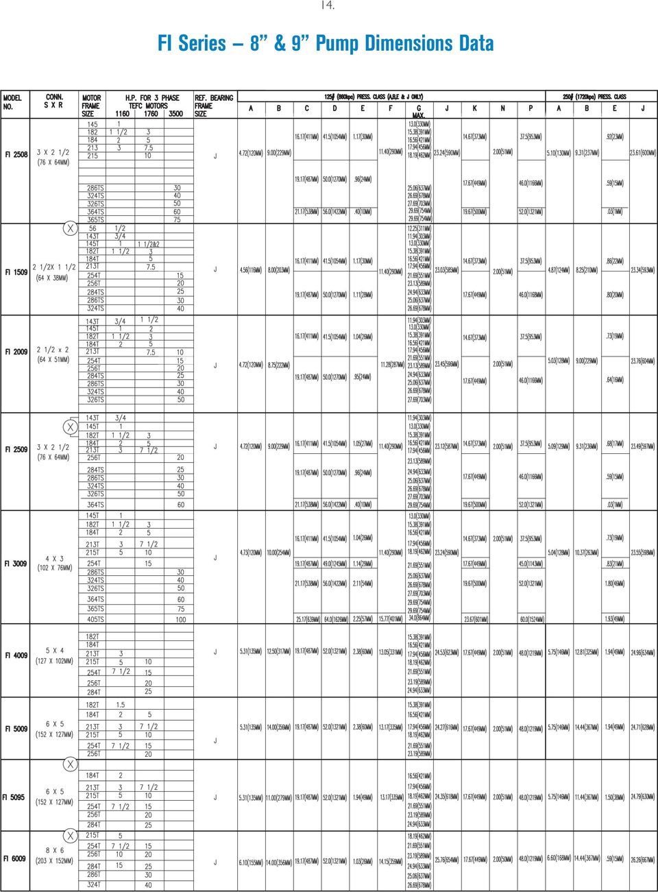
15 14. FI Series 8 & 9 Pump Dimensions Data
16 15. FI Series 10 & 11 Pump Dimensions Data FI 2510C 3 X 2-1/2 (76 X 64MM) 182T 184T 213T 215T 254T 1-1/ H 4.72 (120MM) 9.75 (248MM) (436MM) (1016MM) (1092MM) 1.14 (29MM) 15.38(391MM) 16.56(421MM) (456MM) (306MM) 18.19(462MM) (465MM) 21.69(551MM) (398MM) 2.00 (51MM) (914MM) (991MM) 5.09 (129MM) (256MM) 0.77 (20MM) (474MM)
 15.68 (398MM) 2.00 (51MM) 36.00 (914MM) 39.00 (991MM) 5.09 (129MM) 10.06 (256MM) 0.")
17 16. FI Series 13 Pump Dimensions Data

18 Notes

19 Notes

20 Taco Inc., 1160 Cranston Street. Cranston, RI / (401) / Fax (401) Taco (Canada) Ltd., 8450 Lawson Road, Unit #3, Milton, Ontario L9T 0J8 / (905) / Fax (905)

Model 362A AURORA. 340A/360A Series SINGLE STAGE END SUCTION PUMPS. www.aurorapump.com
 Model 62A MODEL 41A MODEL 44A AURORA 40A/60A Series SINGLE STAGE END PUMPS www.aurorapump.com SINGLE STAGE END PUMPS AURORA 40A/60A Series Single Stage End Suction Pumps Capacities to 4500 G.P.M. (1022
CENTRIFUGAL PUMP OVERVIEW Presented by Matt Prosoli Of Pumps Plus Inc.
 CENTRIFUGAL PUMP OVERVIEW Presented by Matt Prosoli Of Pumps Plus Inc. 1 Centrifugal Pump- Definition Centrifugal Pump can be defined as a mechanical device used to transfer liquid of various types. As
BSM MOTOR DRIVEN CENTRIFUGAL PUMPS
 PRINCIPLE OF OPERATION A hydraulically and dynamically balanced impeller with raised vane sections discharges liquid as a result of the centrifugal force developed in rotation. The head developed is entirely
Centrifugal Fans and Pumps are sized to meet the maximum
 Fans and Pumps are sized to meet the maximum flow rate required by the system. System conditions frequently require reducing the flow rate. Throttling and bypass devices dampers and valves are installed
In-Line Air Separators
 Air Elimination & Control In-Line Air Separators The AC models of air separators deliver all the quality and performance you expect from Taco products. They are built to last with shell, heads and ANSI
TECHNICAL BROCHURE B5-33GB 5GB, 7GB, 10GB, 18GB, 25GB, 33GB HIGH PRESSURE MULTI-STAGE BOOSTER PUMP
 TECHNICAL BROCHURE B-33GB GB, 7GB, 1GB, 18GB, 2GB, 33GB HIGH PRESSURE MULTI-STAGE BOOSTER PUMP FEATURES Multi-stage Design: Provides steady, quiet, vibration free, operation. Optional Stainless Steel Construction:
Pumps: Convert mechanical energy (often developed from electrical source) into hydraulic energy (position, pressure and kinetic energy).
 into hydraulic energy (position, pressure and kinetic energy).") HYDRAULIC MACHINES Used to convert between hydraulic and mechanical energies. Pumps: Convert mechanical energy (often developed from electrical source) into hydraulic energy (position, pressure and kinetic
HYDRAULIC MACHINES Used to convert between hydraulic and mechanical energies. Pumps: Convert mechanical energy (often developed from electrical source) into hydraulic energy (position, pressure and kinetic
CRN5-5 A-FGJ-G-E-HQQE 3x230/400 50HZ
 GRUNDFOS DATA BOOKLET CRN5-5 A-FGJ-G-E-HQQE 3x23/4 5HZ Grundfos Pump 96517184 Thank you for your interest in our products Please contact us for more information, or visit our website http://www.lenntech.com/grundfos/crn5/96517184/crn-5-5-a-fgj-g-e-hqqe.html
Multistage high-pressure multistage centrifugal pumps
 Series description Wilo-Helix V 2 4 6 8 Wilo-Helix V 19-27 7 6 6 Hz - North America 22 2 18 5 16 14 4 12 3 1 V 1 V 19 V 27 8 2 6 1 5 1 15 2 25 3 4 2 35Q[US gpm] H[ft] H[m] Design Vertical multi-stage,
IMPORTANT SAFETY NOTICE
 IMPORTANT SAFETY NOTICE To: Our Valued Customers User safety is a major focus in the design of our products. Following the precautions outlined in this manual will minimize your risk of injury. ITT Goulds
Series 1510 Centrifugal Pumps Technical Bulletin. Bulletin B-207G Bell & Gossett
 Bulletin B-7G Bell & Gossett Series 1 Centrifugal Pumps Technical Bulletin For hydronic heating and cooling systems, industrial, pressure boosting and general pumping applications High efficiency, low
BOWIE PUMPS OPERATION - MAINTENANCE
 BOWIE PUMPS OPERATION - MAINTENANCE PUMPING PRINCIPLE: The meshing owieeof the gears cause a slight depression, with the resulting enmeshing of the gears causing a vacuum drawing the fluid being pumped
FIXED DISPLACEMENT HYDRAULIC VANE PUMPS BQ SERIES
 BQ FIXED DISPLACEMENT HYDRAULIC VANE PUMPS BQ SERIES Versatility, power, compactness and low running costs are the main characteristics of B&C vane pumps. All the components subject to wear are contained
Industrial Process Pump Safety Manual IMPORTANT SAFETY NOTICE
 Industrial Process Pump Safety Manual IMPORTANT SAFETY NOTICE To: Our Valued Customers User safety is a major focus in the design of our products. Following the precautions outlined in this manual will
Practice Problems on Pumps. Answer(s): Q 2 = 1850 gpm H 2 = 41.7 ft W = 24.1 hp. C. Wassgren, Purdue University Page 1 of 16 Last Updated: 2010 Oct 29
: Q 2 = 1850 gpm H 2 = 41.7 ft W = 24.1 hp. C. Wassgren, Purdue University Page 1 of 16 Last Updated: 2010 Oct 29") _02 A centrifugal with a 12 in. diameter impeller requires a power input of 60 hp when the flowrate is 3200 gpm against a 60 ft head. The impeller is changed to one with a 10 in. diameter. Determine the
_02 A centrifugal with a 12 in. diameter impeller requires a power input of 60 hp when the flowrate is 3200 gpm against a 60 ft head. The impeller is changed to one with a 10 in. diameter. Determine the
Pump Selection and Sizing (ENGINEERING DESIGN GUIDELINE)
") Guidelines for Processing Plant Page : 1 of 51 Rev 01 Feb 2007 Rev 02 Feb 2009 Rev 03 KLM Technology #03-12 Block Aronia, Jalan Sri Perkasa 2 Taman Tampoi Utama 81200 Johor Bahru. (ENGINEERING DESIGN GUIDELINE)
Guidelines for Processing Plant Page : 1 of 51 Rev 01 Feb 2007 Rev 02 Feb 2009 Rev 03 KLM Technology #03-12 Block Aronia, Jalan Sri Perkasa 2 Taman Tampoi Utama 81200 Johor Bahru. (ENGINEERING DESIGN GUIDELINE)
Model 413 AURORA. 410 Series SINGLE STAGE SPLIT CASE PUMPS WWW.AURORAPUMP.COM
 Model Model AURORA Series SINGLE SAGE SPLI CASE PUMPS WWW.AURORAPUMP.COM SINGLE SAGE SPLI CASE PUMPS AURORA Series Single Stage Split Case Pumps Capacities to 00 GPM (0 m /hr) Heads to Ft. (0 m) emperatures
Pump and Valve Components and Maintenance
 Pump and Valve Components and Maintenance Outline: 1. Split case and End Suction pumps, industry in the 21 st century, cost of ownership, and performance tips 2. Split case Pumps features, maintenance,
4" SUBMERSIBLE PUMPS
 4" SUBMERSIBLE PUMPS 4" SUBMERSIBLE PUMPS 50/60 HZ Multi-stage centrifugal submersible pumps for clean water in 4" wells. The 4" VSP pump series is carefully designed and manufactured for maximum resistant
VERTICAL TURBINE AND PROPELLER PUMPS
 VERTICAL TURBINE AND PROPELLER PUMPS INTRODUCTION Vertical Turbine and Propeller Pumps Model 7000 Series Turbine Pump Model 800 Series Axial Flow Propeller Pump Model 800 Series Mixed Flow Propeller Pump
CRN32-2-2 A-F-G-E-HQQE 3x400D 50 HZ
 GRUNDFOS DATA BOOKLET CRN32-2-2 A-F-G-E-HQQE 3x4D 5 HZ Grundfos Pump 96122352 Thank you for your interest in our products Please contact us for more information, or visit our website http://www.lenntech.com/grundfos/crn32/96122352/crn-32-2-2-a-f-g-e-hqqe.html
TOPIC: 191004 KNOWLEDGE: K1.01 [3.3/3.5] Which one of the following contains indications of cavitation in an operating centrifugal pump?
![TOPIC: 191004 KNOWLEDGE: K1.01 [3.3/3.5] Which one of the following contains indications of cavitation in an operating centrifugal pump?](/thumbs/17/105210.jpg "TOPIC: 191004 KNOWLEDGE: K1.01 [3.3/3.5] Which one of the following contains indications of cavitation in an operating centrifugal pump?") KNOWLEDGE: K1.01 [3.3/3.5] P21 Which one of the following contains indications of cavitation in an operating centrifugal pump? A. Low flow rate with low discharge pressure. B. Low flow rate with high discharge
KNOWLEDGE: K1.01 [3.3/3.5] P21 Which one of the following contains indications of cavitation in an operating centrifugal pump? A. Low flow rate with low discharge pressure. B. Low flow rate with high discharge
- CONSTRUCTIONS 300 SECTIONAL VIEW 300 MECHANICAL SEAL 301 - DIMENSIONS AND WEIGHT 400 PUMP 400 PACKING 401
 CONTENTS Page - SPECIFICATIONS 200 SELECTION CHART 201 TYPE KEY AND CURVE SPECIFICATIONS 202 PERFORMANCE CURVE 70 204 PERFORMANCE CURVE 90 205 PERFORMANCE CURVE 120 206 PERFORMANCE CURVE 200 207 - CONSTRUCTIONS
CDX. EBARA PUMPS EUROPE S.p.A. CENTRIFUGAL PUMPS. Page - CONTENTS 100
 CONTENTS Page - CONTENTS 100 - SPECIFICATIONS 200 SELECTION CHARTS 201 PERFORMANCE CHART 70 202 PERFORMANCE CHART 90 203 PERFORMANCE CHART 120 204 PERFORMANCE CHART 200 205 - CONSTRUCTIONS 300 SECTIONAL
FIXED DISPLACEMENT HYDRAULIC VANE PUMPS BQ SERIES
 BQ FIXED DISPLACEMENT HYDRAULIC VANE PUMPS BQ SERIES Versatility, power, compactness and low running costs are the main characteristics of B&C vane pumps. All the components subject to wear are contained
Installation and Operating Instructions Installation Instructions for SS EPE-316L Series
 INSTR3010 0406 Installation and Operating Instructions Installation Instructions for SS EPE-316L Series Congratulations on your purchase of this Aqua-Pure high flow, single housing filtration system. This
Vertical Pumps for the Oil & Gas Industry
 Vertical Pumps for the Oil & Gas Industry ITT API Expert ITT Commitment ITT is committed to the Oil and Gas market, which is the largest segment of our business. We have been investing in technology to
FIXED DISPLACEMENT HYDRAULIC VANE PUMPS BQ SERIES
 BQ FIXED DISPLACEMENT HYDRAULIC VANE PUMPS BQ SERIES Versatility, power, compactness and low running costs are the main characteristics of B&C vane pumps. All the components subject to wear are contained
V47 Series Temperature Actuated Modulating Water Valves
 V47 Series Temperature Actuated Modulating Water Valves Master Catalog 125 Valves, Miscellaneous (Other Than Gas) Section V Product Bulletin V47 Issue Date 0286 Application The V47 modulating valves regulate
FAIRBANKS NIJHUIS FIRE PUMPS. www.fairbanksnijhuis.com
 FAIRBANKS NIJHUIS FIRE PUMPS www.fairbanksnijhuis.com FAIRBANKS NIJHUIS Long established as a leading fire pump manufacturer, Fairbanks Nijhuis offers a broad range of horizontal and vertical split case,
APCO SLOW CLOSING AIR/VACUUM VALVES
 BULLETIN 1 JULY 01 APCO SLOW CLOSING AIR/VACUUM VALVES Series 1900 APCO Slow Closing Air/Vacuum s Maximum Air Flow Velocity in Good Pipeline Design The Air/Vacuum operates in the normal fashion allowing
CENTRIFUGAL PUMP SELECTION, SIZING, AND INTERPRETATION OF PERFORMANCE CURVES
 CENTRIFUGAL PUMP SELECTION, SIZING, AND INTERPRETATION OF PERFORMANCE CURVES 4.0 PUMP CLASSES Pumps may be classified in two general types, dynamic and positive displacement. Positive displacement pumps
Horizontal Jet Pumps 1/3-1-1/2 HP
 Horizontal Jet s 1/3-1-1/2 FW01 0909 Supersedes 0409 The CPJ, CPH and EK models feature the famous Flint and Walling Service Plus motor, available in either NEMA J or Uni-frame flange construction. The
2CP. Twin-impeller pumps PERFORMANCE RANGE INSTALLATION AND USE APPLICATION LIMITS OPTIONALS AVAILABLE ON REQUEST CONSTRUCTION AND SAFETY STANDARDS
 2CP Twin-impeller pumps PERFORMANCE RANGE Flow rate up to 40 l/min (27 m³/h) Head up to 112 m APPLICATION LIMITS Manometric suction lift up to 7 m Liquid temperature between -10 C and +90 C Ambient temperature
Overview. Introduction Cooling Tower Basics Principles of Operation Types of Cooling Towers Common Applications Design Considerations
 Stephen Lowe ASHRAE Hampton Roads Chapter Past President AECOM Design Mechanical Engineering Discipline Manager, Virginia Beach Division Professional Engineer Commonwealth of Virginia, NCEES BSME University
Max. Head (m) LVR3-7-220V 3 32 5 44 0,55 10 50Hz ~ 220 V Oval Flange G1. LVR3-7-380V 3 32 5 44 0,55 10 50Hz ~ 380 V Oval Flange G1
 LVR3-7-220V 3 32 5 44 0,55 10 50Hz ~ 220 V Oval Flange G1. LVR3-7-380V 3 32 5 44 0,55 10 50Hz ~ 380 V Oval Flange G1") Description NordicFlow s keep the system pressurized during normal conditions and prevent unnecessary activation of the main pump. They have compact design, high efficiency, low noise, reliable sealing
Description NordicFlow s keep the system pressurized during normal conditions and prevent unnecessary activation of the main pump. They have compact design, high efficiency, low noise, reliable sealing
OUR PRODUCTS TRH-TRS-TRM-TRV. LIQUID RING VACUUM PUMPS AND COMPRESSORS Capacity up to 2100 ACFM Vacuum to 29 Hg. Our Other Products.
 Our Other Products OUR PRODUCTS Liquid Ring & Rotary Vane Vacuum Pumps and Systems Liquid Ring Vacuum Pumps: 3 CFM to,000 CFM Liquid Ring Compressors up to 1 psig Heat Transfer Pumps for hot thermal oils
NORMAN FILTER COMPANY PRODUCT OVERVIEW
 NORMAN FILTER COMPANY PRODUCT OVERVIEW LEADING THE WAY IN QUALITY FILTRATION WWW.NORMANFILTERS.COM FILTER ELEMENT INTERCHANGE Tee-Type Filter 4500, 14500, 34500, and 54500 Series Mini Tee-Type Filter 4100
SJT / SJM / SJP Large Vertical Pumps
 SJT / SJM / SJP Large Vertical Pumps The Heart of Your Process SJT, SJM, SJP Large Vertical Pumps Product Overview SJT Turbine Ns 1800 < 5000 nq 35 < 110 SJM Mixed Flow Ns 5800 < 8300 nq 113 < 161 SJP
James M. Pleasants Company
 James M. Pleasants Company SUBMITTAL DATA GAINESVILLE MECHANICAL DECEMBER 20, 2013 PROJECT: GSU: J-183 HUMANITIES LAW BLDG. QUOTE NO:12116 ENGINEER: STEVENS & WILKINSON GASKETED PLATE HEAT EXCHANGER Tag:
Air Eliminators and Combination Air Eliminators Strainers
 Description Air Eliminators and Combination Air Eliminator Strainers are designed to provide separation, elimination and prevention of air in piping systems for a variety of installations and conditions.
Float and Thermostatic Traps Series H, C and X
 Hoffman Specialty Installation & Maintenance Instructions HS-(E) and Thermostatic Traps Series H, C and X Series C & NPT Series C NPT Series X NPT Series C NPT Series H Ratings Maximum Max. Operating NPT
DARTMOUTH COLLEGE DESIGN January 3, 2012 & CONSTRUCTION GUIDELINES
 SECTION 15062 STEAM AND CONDENSATE PIPING PART 1 DESIGN DIRECTIVES 1.1 QUALITY ASSURANCE A. Comply with the provisions of the following: 1.2 DESIGN CRITERIA 1. ASME B 31.9 Building Services Piping : for
Equivalents & Conversion Factors 406 Capacity Formulas for Steam Loads 407 Formulas for Control Valve Sizing 408-409
 Engineering Data Table of Contents Page No. I II Formulas, Conversions & Guidelines Equivalents & Conversion Factors 406 Capacity Formulas for Steam Loads 407 Formulas for Control Sizing 408-409 Steam
SUPER-TITAN. Split-case pumps with power, performance and reliability for a world of applications
 SUPER-TITAN Split-case pumps with power, performance and reliability for a world of applications The Prestige. The Performance. SUPER-TITAN PUMPS Features The TKL Super-Titan pump makes a significant contribution
= water horsepower WHP brake horsepower QH WHP = (222) ( 33,000 ft-lbs/min-hp)( 7.481 gal/ft ) 1 HP=0.746 kw
 ( 33,000 ft-lbs/min-hp)( 7.481 gal/ft ) 1 HP=0.746 kw") Lecture 11 Pumps & System Curves I. Pump Efficiency and Power Pump efficiency, E pump E pump = water horsepower WHP brake horsepower = BHP (221) where brake horsepower refers to the input power needed
Lecture 11 Pumps & System Curves I. Pump Efficiency and Power Pump efficiency, E pump E pump = water horsepower WHP brake horsepower = BHP (221) where brake horsepower refers to the input power needed
AURORA. 1030 AND 1040 Series SUCTION DIFFUSERS, COMBINATION AND TRIPLE DUTY VALVES WWW.AURORAPUMP.COM
 UROR 1030 ND 1040 Series SUCTION DIFFUSERS, COMINTION ND TRIPLE DUTY VLVES WWW.URORPUMP.COM UROR 1030 ND 1040 Series Suction Diffusers, Combination and Triple Duty Valves Designed for Direct Mounting on
OHV / OHVL Type OH3 Vertical Inline Pumps ISO 13709 (API 610)
") OHV / OHVL Type OH3 Vertical Inline Pumps ISO 13709 (API 610) The Heart of Your Process OHV / OHVL Type OH3 Vertical Inline Pumps ISO 13709 (API 610) OHV OHVL OHV/OHVL Sales Presentation slide
OHV / OHVL Type OH3 Vertical Inline Pumps ISO 13709 (API 610) The Heart of Your Process OHV / OHVL Type OH3 Vertical Inline Pumps ISO 13709 (API 610) OHV OHVL OHV/OHVL Sales Presentation slide
VM, VMC, VMN. Vertical Multistage Centrifugal Pump, 60Hz
 VM, VMC, VMN Vertical Multistage Centrifugal Pump, 60Hz Approvals CERTIFICATE IQNet and SQS hereby certify that the organisation Swiss Pump Company AG 3645 Thun-Gwatt Switzerland Whole Company Design,
Rexroth Hydraulic Pump A10VO Series User Manual
 Rexroth Hydraulic Pump A10VO Series User Manual Rexroth Hydraulic pump A10VO Series User Manual Revised 5/1/2009 Page 1 of 12 Functional Purpose This pump is preferred over a fixed displacement (gear)
Flygt Ball Check Valves
 4/13 Supersedes: 6/96 The basic purpose of a check valve is to permit flow in one direction, prevent flow in the opposite direction and perform this function automatically and with minimum maintenance.
KS Vertical In-Line Pump
 KS Vertical In-Line Pump 302-032 Installation, Operation & Maintenance Manual SUPERSEDES: July 1, 2010 EFFECTIVE: August 1, 2012 Plant ID No. 001-1014 SAFETY REQUIREMENTS 1. IMPORTANT! These instructions
Mechanical shaft seal types and sealing systems
 Chapter 2 Mechanical shaft seal types and sealing systems 1. Mechanical shaft seal types 2. Sealing systems 3. Selecting a mechanical shaft seal Mechanical shaft seal types and sealing systems 1. Mechanical
T U R B I N E G A S M E T E R
 TURBINE GAS METER TURBINE GAS METER CGT 1 2 3 4 5 6 7 Design and function page 2 General technical data page 3 Measurement outputs page 4 Dimensions and weights page 5 Performance page 7 Pressure loss
MOBILE FIRE - RESCUE DEPARTMENT FIRE CODE ADMINISTRATION
 MOBILE FIRE - RESCUE DEPARTMENT FIRE CODE ADMINISTRATION Fire Pump Plan Review 2009 International Fire Code and NFPA 20 Date of Review / / BLD201 - Project Address: Project Name: Contractor s Business
Flows to 18 GPM. Pressure to 100 PSI
 Markets Agriculture-fertilizers, pesticides Automotive-coolants, lubricants Book Mfg-adhesives, glue Construction & Mining-lubricants, fuels, coolants Filtration System Pumps-portable, stationary Food
AC Electric Motors best practice
 If you want to learn more about best practice machinery maintenance, or world class mechanical equipment maintenance and installation practices, follow the link to our Online Store and see the Training
300 SERIES 331, 332, 333, 344, 356 AND 367 MODELS
 Section: MOYNO 500 PUMPS Page: 1 of 8 Date: March 1, 1998 SERVICE MANUAL MOYNO 500 PUMPS 300 SERIES 331, 332, 333, 344, 356 AND 367 MODELS Mechanical Seal Models Packing Gland Models MODELS DESIGN FEATURES
Model 1210C Battery Powered Pump Shown. Description
 12 Volt DC Rotary Vane Pump Series 1200C Model 1210C Battery Powered Pump Shown Description of Included Models Model Number FR1205C FR1210C FR1211C FR2410C FR2411C Description Basic 12 volt DC pump with
DeZURIK 3" (75MM) & LARGER ECCENTRIC PLUG VALVES
 & LARGER ECCENTRIC PLUG VALVES") BULLETIN 12.00-1C SUPERSEDES 12.00-1C & 12.60-1A JUNE 2014 DeZURIK 3" (75MM) & LARGER ECCENTRIC PLUG VALVES www.dezurik.com The DeZURIK Eccentric Plug Valve In thousands of installations worldwide, DeZURIK
BULLETIN 12.00-1C SUPERSEDES 12.00-1C & 12.60-1A JUNE 2014 DeZURIK 3" (75MM) & LARGER ECCENTRIC PLUG VALVES www.dezurik.com The DeZURIK Eccentric Plug Valve In thousands of installations worldwide, DeZURIK
GS-General Service Control Valves
 GS-General Service Control Valves GS-General Service Valves The GS-General Service Valves continue Copes-Vulcan s tradition of designing and manufacturing control valves that provide both exceptional service
Pump Maintenance - Repair
 Pump Maintenance - Repair Brian Trombly Mo Droppers Cummins Bridgeway, Gaylord, Mi The basic centrifugal pump consists of two main elements: 1. The rotating element which includes an impeller and a shaft.
Fire Pump Plan Review March 2010
 Fire Pump Plan Review March 2010 Date of Review: / / Permit Number: Business/Building Name: Address of Project: Designer Name: Designer s Phone: Contractor: Contractor s Phone: Occupancy Classification:
JOB or CUSTOMER: ENGINEER: CONTRACTOR: SUBMITTED BY: SPECIFICATION REF: QUANTITY TAG NO. MODEL NO. GPM FEET LEAD LENGTH COMMENTS.
 Redi-Flo2, 2 Environmental Submersible Pumps MP1 Submittal Data QUANTITY TAG NO. MODEL NO. GPM FEET LEAD LENGTH COMMENTS Technical Data Motor Type: Water-Filled, variable speed submersible Maximum Fluid
The conditions below apply to the curves shown on the following pages.
 GENERAL INFORMATION STAINLESS STEEL, SILVERLINE, EVERGREEN & GOLDLINE SERIES PERFORMANCE CURVE CONDITIONS The conditions below apply to the curves shown on the following pages. a. The Performance curves
PUMPS TYPE OF PUMP PRESSURE/FLOW RATING CHARACTERISTICS. Centrifugal Low Pressure/High Flow Flow changes when
 PUMPS Pumps provide the means for moving water through the system at usable working pressures. The operation and maintenance of these pumps are some of the most important duties for many water utility
Unit 24: Applications of Pneumatics and Hydraulics
 Unit 24: Applications of Pneumatics and Hydraulics Unit code: J/601/1496 QCF level: 4 Credit value: 15 OUTCOME 2 TUTORIAL 1 HYDRAULIC PUMPS The material needed for outcome 2 is very extensive so there
C. starting positive displacement pumps with the discharge valve closed.
 KNOWLEDGE: K1.04 [3.4/3.6] P78 The possibility of water hammer in a liquid system is minimized by... A. maintaining temperature above the saturation temperature. B. starting centrifugal pumps with the
PRESSURE REDUCING CONTROL VALVE
 Schematics Throttles to reduce high upstream pressure to constant lower downstream pressure Low Flow By-Pass controls at low flows 4 PRESSURE REDUCING CONTROL VALVE with LOW FLOW BY-PASS FEATURE Main Line
Pump ED 101. Positive Displacement Pumps. Part I Reciprocating Pumps
 Pump ED 101 Positive Displacement Pumps Part I Reciprocating Pumps Joe Evans, Ph.D http://www.pumped101.com There are many pump designs that fall into the positive displacement category but, for the most
VAL-MATIC VALVE AND MANUFACTURING CORP. 905 RIVERSIDE DRIVE, ELMHURST, IL 60126 TEL. (630) 941-7600 FAX.
 941-7600 FAX.") Cavitation in Valves VAL-MATIC VALVE AND MANUFACTURING CORP. 905 RIVERSIDE DRIVE, ELMHURST, IL 60126 TEL. (630) 941-7600 FAX. (630) 941-8042 www.valmatic.com CAVITATION IN VALVES INTRODUCTION Cavitation
Cavitation in Valves VAL-MATIC VALVE AND MANUFACTURING CORP. 905 RIVERSIDE DRIVE, ELMHURST, IL 60126 TEL. (630) 941-7600 FAX. (630) 941-8042 www.valmatic.com CAVITATION IN VALVES INTRODUCTION Cavitation
Motors. Bearing Assemblies & Bearing Cartridge Kit
 Motors High quality Pro-Fit motors are designed to replace all Bell & Gossett* and Armstrong** motors up to 3 HP. Permanently lubricated, sleeve bearing or ball bearing construction make Pro- Fit replacement
Domestic Hot Water Recirculation Systems Application, Selection & Installation Guide
 Water Circulation Pumps & Circulators Domestic Hot Water Recirculation Systems Application, Selection & Installation Guide Taco Catalog # 100-41 Supersedes: 08/07/15 Effective Date: 09/01/15 Printed in
ELECTRIC/DIESEL FIRE PUMP CHECK LIST
 BUILDING NAME: DESIGNER: SCO REPRESENTATIVE: PUMP MANUF.: LOCATION: INSTALLER: DATE: OWNER NAME: INSTALLATION Certificate for flushing and hydrostatic test furnished Piping been hydrostatically tested
ZOP, ZOT SIGMA PUMPY HRANICE GEAR PUMPS 426 1.99 21.04
 SIGMA UMY HRANICE GEAR UMS SIGMA UMY HRANICE, s.r.o. Tovární 605, 753 01 Hranice, Czech Republic tel.: +420 581 661 111, fax: +420 581 602 587 Email: [email protected], 426 1.99 21.04 Application In
08.08 Vic-Check Valves
 The check valves are a product of computer-assisted innovative engineering with quality features including a new hydrodynamically efficient profile. The Vic-Check valve utilizes a spring-assisted, single-disc
Selection Of Centrifugal Pumping Equipment 1
 Circular 1048 Selection Of Centrifugal Pumping Equipment 1 Dorota Z. Haman, Fedro S. Zazueta, Forrest T. Izuno 2 INTRODUCTION The pump is an essential component of an irrigation system. Proper selection
Steam System Best Practices Condensate System Piping
 Steam System Best Practices Condensate System Piping Summary The best method for improving steam system energy efficiency, reducing chemical costs, and reducing make-up water costs is to return the maximum
Pumps SELECTION OF A PUMP
 Pumps SELECTION OF A PUMP A water system needs to move the water produced from the source to its customers. In almost all cases in Minnesota, the source is at a lower elevation than the user so the water
VXT. Open Cooling Towers. Open Cooling Towers. Product Detail VXT - B 1. Engineering Data... B2. Structural Support... B6
 - B 1 Product Detail Engineering Data... B2 Structural Support... B6 Engineering Specifications... B9 - B 2 Engineering Data REMARK: Do not use for construction. Refer to factory certified dimensions &
Hydraulic Pump/Motor Division Hydraulic Pump/Motor Division
 Parker Piston Pumps Otsego Core Competency... Piston Pumps PAVC Series : 4 displacements from 33-100 cc/r, 207 Bar, 3000 RPM PVP Series : 9 displacements from 16-140 cc/r, 250 Bar, 3000 RPM PV Plus : 12
Owner s Manual. Models: 2S5P & 3S5P OPERATION AND MAINTENANCE OF SELF-PRIMING CENTRIFUGAL TRASH PUMPS PEDESTAL DRIVE
 Owner s Manual Models: 2S5P & 3S5P OPERATION AND MAINTENANCE OF SELF-PRIMING CENTRIFUGAL TRASH PUMPS PEDESTAL DRIVE WARNING!! Installation & Operating Instructions Self-Priming Centrifugal Pump DO NOT
Goulds AF. Axial Flow Pump
 Goulds AF Axial Flow Pump Goulds AF The Industry Leader in Circulating Pump Technologies Fabricated design 42-66 (1050-1600 mm) (shown with optional spring mounted base) Cast design 6-36 (150-900 mm) Goulds
Pump Specifications 250 Series Submersible Sump / Effluent Pump 2 Solids handling
 Pump Specifications 250 Series Submersible Sump / Effluent Pump 2 Solids handling 250_P1 R10/7/2015 Copyright 2015 Liberty Pumps Inc. All rights reserved. Specifications subject to change without notice.
Standard offering (pumps)
") MDM PUMPS LTD Spring Lane Malvern, Worcs. England. WR14 1BP This outlines what we typically supply. Tel: +44 (0)1684 892678 Fax: +44 (0)1684 892841 E-mail: Website: Standard offering (pumps) [email protected]
MDM PUMPS LTD Spring Lane Malvern, Worcs. England. WR14 1BP This outlines what we typically supply. Tel: +44 (0)1684 892678 Fax: +44 (0)1684 892841 E-mail: Website: Standard offering (pumps) [email protected]
SIRIUX. SINGLE AND DOUBLE HIGH EFFICIENCY CIRCULATORS Heating Air-conditioning OPERATING LIMITS APPLICATIONS. 28 m 3 /h* Heads up to: Flows up to:
 OPERATING LIMITS Flows up to: m /h* Heads up to: m C Max operating pressure: bars Temperature range: - à + C Max ambient temperature: + C ND of orifices: à * m /h: parallel operation SIRIUX SINGLE AND
GT Horizontal Split Casing Pumps
 GT Horizontal Split Casing Pumps 302-054 Operations and Maintenance Manual SUPERSEDES: New EFFECTIVE: March 1, 2009 Plant ID No. 001-3930 SAFETY REQUIREMENTS These operating instructions must be complied
Index 11.1. Page. Pumping Systems...11.2-11.4 Intensifiers...11.5 Gas Boosters...11.6-11.7 High Pressure Generators...11.8-11.9
 Pumping Systems, Intensifiers, Gas Boosters and High Pressure Generators High Pressure Equipment Company produces a number of components and systems for general industrial, elevated pressure applications.
TD10. Selecting Circulators. Technical Documents. Taco Radiant Made Easy Application Guide STEP 1: ESTABLISH THE TARGET FLOW RATE FOR THE SYSTEM
 EFFECTIVE:August, Taco Radiant Made Easy Application Guide Selecting Circulators Technical Documents TD SUPERSEDES: New This article shows you how to select a Taco circulator that lets the hydronic system
An SPX Process Equipment Operation. Universal II Industrial Series Rotary Positive Displacement ECP Pumps
 An SPX Process Equipment Operation Universal II Industrial Series Rotary Positive Displacement ECP Pumps New levels of performance. Reduced operational and maintenance costs. For more than half a century,
PBX Series Quick Fit Connector Bimetallic Steam Traps
 6262100/6 IM-P626-01 ST Issue 6 PBX Series Quick Fit Connector Bimetallic Steam Traps Installation and Maintenance Instructions 1. Safety information 2. General product information 3. Installation 4. Commissioning
5.23.22 STEAM AND CONDENSATE PIPING AND PUMPS DESIGN AND CONSTRUCTION STANDARD PART 1: GENERAL. 1.01 Purpose:
 PART 1: GENERAL 1.01 Purpose: A. This standard is intended to provide useful information to the Professional Service Provider (PSP) to establish a basis of design. The responsibility of the engineer is
OPERATION & MAINTENANCE MANUAL. for VERTICAL INLINE PUMPS
 OPERATION & MAINTENANCE MANUAL for VERTICAL INLINE PUMPS PATTERSON PUMP COMPANY A SUBSIDIARY OF THE GORMAN-RUPP COMPANY PO Box 790 9201 Ayersville Road Toccoa, Georgia 30577 Telephone: 706-886-2101 SAFETY
Troubleshooting for: Premier Supplier of Pumps & Parts
 Premier Supplier of Pumps & Parts Troubleshooting for: 115 Hilton Street West Easton, PA 18042 USA (800)854-0539 fax: (800)926-9508 http://www.processflo.com 4 Operation Pay attention to possible faults.
Morrison Bros. Co. General Product Specifications
 Morrison Bros. Co. General Product Specifications Tank Mounted Spillbox The spill containment device is manufactured to contain spills and drips that may occur at the fill point on aboveground storage
POLARIS AIR COMPRESSOR SERIES. engineering. excellence. stellar. performance. A World Leader for Centrifugal Compressors
 POLARIS AIR COMPRESSOR SERIES engineering excellence stellar performance P - 3 0 0 RELIABLE 100% OIL-FREE ENGINEERED AIR A World Leader for Centrifugal Compressors It s simple: The Polaris Air Compressor
A BRIEF INTRODUCTION TO CENTRIFUGAL PUMPS
 A BRIEF INTRODUCTION TO CENTRIFUGAL PUMPS figure below is a cross section of a centrifugal pump and shows the two basic parts. Joe Evans, Ph.D IMPELLER This publication is based upon an introductory, half
TECHNICAL INFORMATION Bulletin
 Peerless Pump Company 2005 Dr. M.L. King Jr. Street, P.O. Box 7026, Indianapolis, IN 46207-7026, USA Telephone: (317) 925-9661 Fax: (317) 924-7338 www.peerlesspump.com www.epumpdoctor.com TECHNICAL INFORMATION
Vertical selfpriming Side-Channel Pumps Type WPV
 Vertical selfpriming Side-Channel Pumps Type WPV FIELD OF APPLICATION The side-channel pumps are selfpriming and operate more economically (better efficiency) than normal centrifugal pumps when handling