Colour codes. Diagrams index
|
|
|
- Annabelle Manning
- 9 years ago
- Views:
Transcription
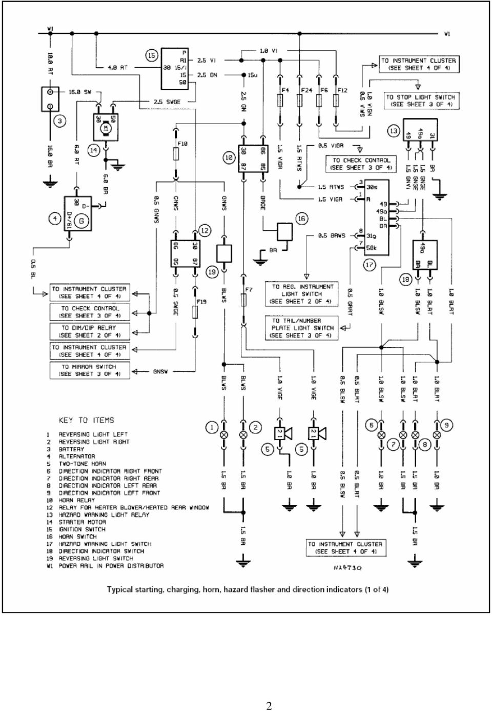
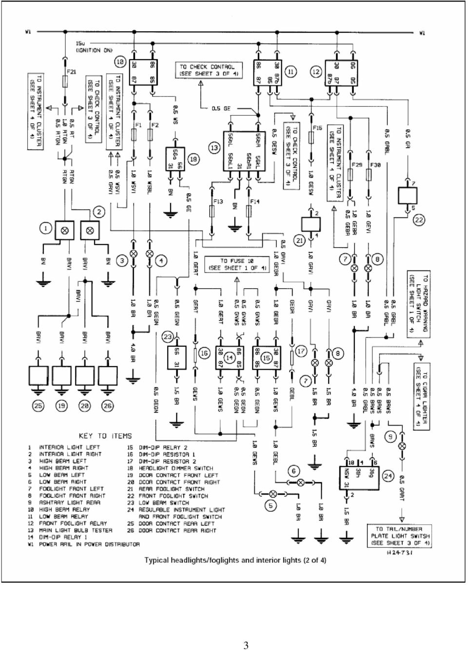
1 BMW - electrical systems - WIRING DIAGRAM Models covered : 3-Series (E30) 316 (83 to 88), 316i (88 to 91), 318i (83 to 91), 320i (87 to 91), 325i (87 to 91). Also Touring and Convertible versions of these models 5-Series (E28) 518 (81 to 85), 518i (85 to 88), 525i (81 to 88), 528i (81 to 88), 535i (85 to 88), M535i (85 to 88) 5-Series (E34) 518i (90 to 91), 520i (88 to 91), 525i (88 to 91), 530i (88 to 91), 535i (88 to 91) Engines covered 1596 cc, 1766 cc, 1795 cc, 1990 cc, 2494 cc, 2788 cc, 2986 cc & 3430 cc Since it isn t possible to include all wiring diagrams for every model year covered, the following diagrams are those that are typical and most commonly needed. BK BL BR GE GN GR GY OR PK R RS RT SW TN V VI W WS Y Colour codes Black Blue Brown Yellow Green Green or Grey Grey Orange Pink Red Pink Red Black Tan Violet Violet White White Yellow Diagrams index Typical - starting, charging,horn, hazard flasher end direction indicator 2 Typical - headlights/foglights and interior lights 3 Typical - check control, elettric mirrors, stop and parking light 4 Typical - Motronic engine control system wiring diagram 5 Typical - cruise control system wiring diagram 8 Typical - wiring diagram for the central locking, burglar alarm, on-board computer, additional heater end digital clock 10 Typical - headlighl washer syslem wiring diagram 13 Typical - electric window system wiring diagram 15 Typical - air conditioning system wiring diagram 17 Typical - wiring diagram for heated seats 19 Typical - wiring diagram for memory power seats 21 Typical - wiring diagram for power seats without memory 24 Typical - radio wiring diagram 26 Typical - Jetronic system wiring diagram 28

2 2
3 3
4 4

5 5
6 6
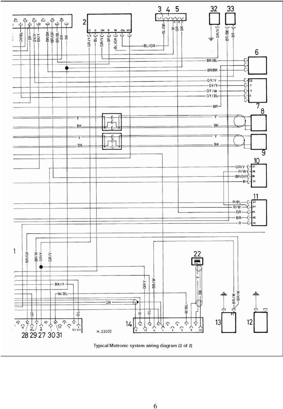
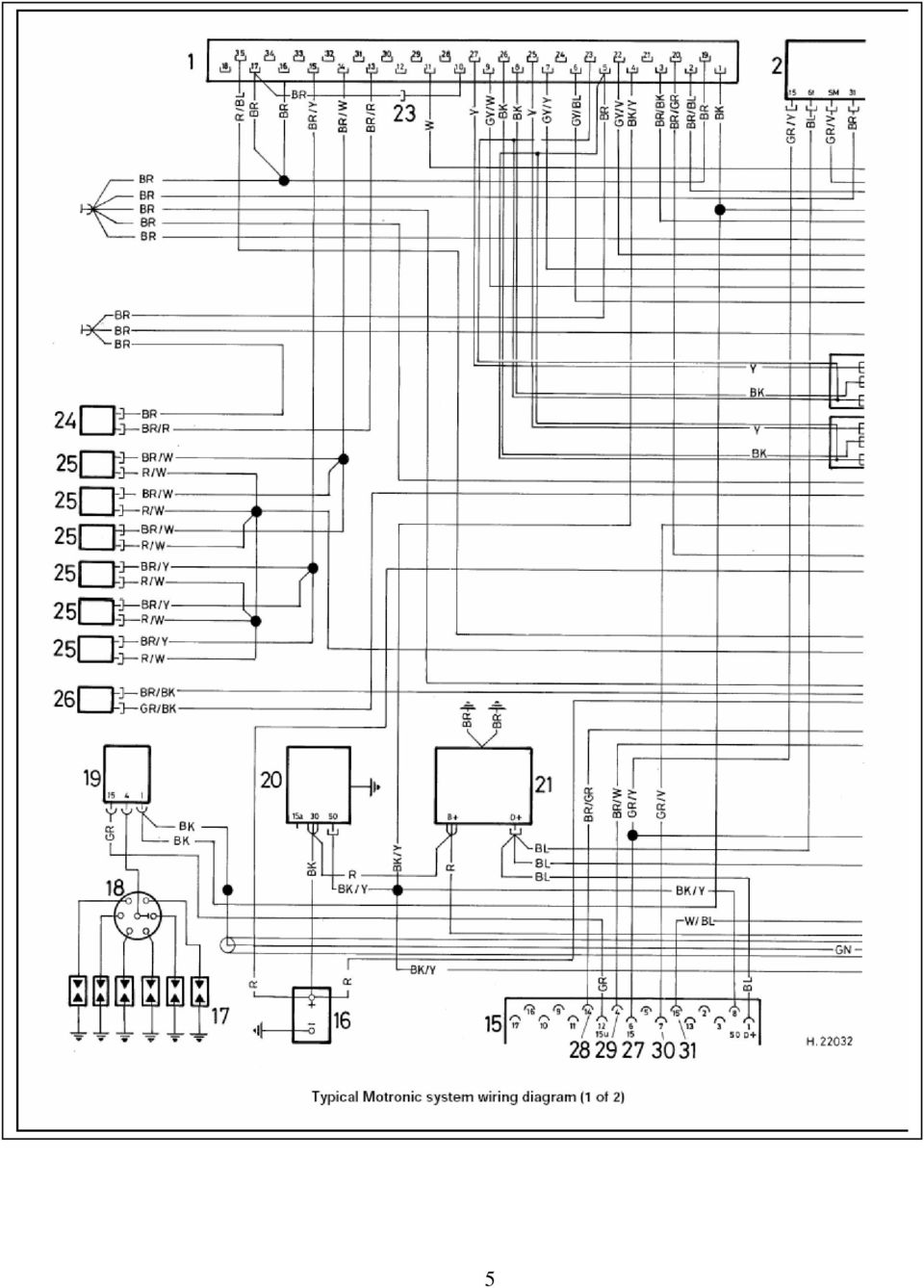
7 Key to Motronic engine control system wiring diagram (picture 1/1 1/2) 1. Electronic Control Unit (ECU) 18. Distributor 2. Speed control relay 19. Ignition coil 3. Temperature switch 20. Starter 4. Air conditioner 21. Altenator 5. Car wire harness connection 22. Position transmitter 6. Throttle switch 23. Plug dìsconnected for automatic 7. Airflow sensor transmission 8. Speed sensor 24. Coolant temperature sensor 9. Reference mark sensor 25. Fuel injector 10. Relay Relay Oil pressure switch 13. Temperature transmitter 14. Diagnosis conneclion 15. Engine plug 16. Battery 17. Spark plugs 26. Solenoid 27. Electric power distributor 28. Oil pressure 29. Temperature gauge 30. Electric fuel pump 31. Service indicator 32. Drive motor 33. Temperature switch 7

8 8 Picture 2

9 Key to cruise control system wiring diagram (picture 2) 1. Plug connection - centre section to instrument cluster (26-pin) 2. Steering column switch 3. Instrument cluster 4. Plug connection range indicator 5. Range indicator D 6. Range indicator N 7. Range indicator R 8. Plug connoction - speedometer outlet 9. Connection - instrument cluster (2-pin) 10. Plug connection - steering column switch 11. Plug connection - special equipment 12. Steering column switch 13. Plug connection rear section to centre section (29-pin) 14. Stoplight switch 15. Plug connection-drive motor 16. Connection - clutch swltch to bridge 17. Stoplight left 18. Stoplight right 19. Electronic control - cruise control 20. Drive motor- cruise control 21. Bridge (only for automalic transmission) 22. Clutch switch 9

10 10 Picture 3/1

11 11 Picture 3/2

12 Key to wiring diagram for the central locking, burglar alarm, on-board computer, additional heater end digital clock (picture 3/1 3/2) 1. Plug - rear section to centre section 2. Connection for special equipmenl plug 3. Connaction for central loçk control unit 4. Central lock electronic control unit (A pillar end plate) 5. Plug - driver's door wire to rear section 6. Plug - central lock connecting wire to driver's door wire 50(13-pin) 7. Plug central lock connecting wire to passenger's door wire 8. Plug driver's door cenlral lock wire to swilch 9. Central lock switch/unblocking arrest (driver's door,on lock) 10. Connection for centralloçk motor to driver's door (6-pin) 11. Central lock motor - driver's door 12. Plug-passenger's door wire to microswitch 13. Microswitch (passenger's door,on lock) 14. Central lock motor-passenger's door 15. Central lock motor-pàssenger's door 16. Connection for central lock motor to boot lid(6-pin) 17. Central lock motor - bool lid 18. Connection for cenlral lock motor to fuel filler flap (6-pin) 19. Central lock motor-fuel filler flap 20. Connection for central lock motor to left rear door(6-pin) 21. Central lock molor - left rear door 22. Connection for central lock motor to right door(6-pin) 23. Plug central lock connecting wire to right rear door (7-pin) 24. Plug cantral lock connecting wire lo left rear door 17-pin) 25. Central lock motor- right rear door 26. Rear window heater switch 27. Burglar alarm electronic control unit (left of steering column) 28. Connection for burglar alarm electronic control unit I (26-pin) 29. Connection for relay box (4-pin) 30. Connection for burglar alarm electronic conlroi unii II (4-pin) 31. Plug 150 (in main wire harness) 32. Light diode for burglar alarm 33. Plug for boot light 34. Boot lighl 35. Door contact switch front left 36. Door contact switch tront right 37. Door contact switch rear left 38. Door contact switch rear right 39. Boot lid contact 40. Bonnet contact 41. Rear window heater 42. Plug - centre section to wire for on board computer/burgiar alarm 43. Horn Plug for light diode 45. Diode 46. Plug - burglar alarm wire to central lock connecting wire 47. Chime (left of steering column) 48. Connection for chime 49. Plug - centre section to LE-Jetronic wire harness 50. Ignition switch 51. Remote control switch for on-board computer 52. Plug on-board computer to outside temperature sensor wire 53. Plug - outside temperature sensor wire to outside temperature sensor 54. Outside temperature sensor (lower front panel) 55. Plug - extra heater wire to automatic aerial 56. Parked car heating electronic control unit (on parked car heater underneath righit seat) 57. Connection for electronic control unit 58. Relay for parked car heater (on heater) 59. Plug - on-board computer wire to extra heater wire 60. Plug - centre section to instrument cluster 61. Connection for instrument cluster 62. On-board computer electronic contol unit (right of instrument cluster) 63. Connection for on-board computer 64. Connection for instrument cluster II 65. Instrument cluster 66. Plug- rear section to instrument cluster 67. Plug - digital clock wire to instrument cluster 68. Plug-extra wire to heater wire 69. Plug-heater wire to fuel pump wire 70. Connection for heater 71. Ballast resistor in heater 72. Thermoswitch (parked car heater) 73. Heater motor 74. Overheating switch (parked car heater) 75. Heater plug for parked car heater 76. Heater 77. Fuel pump 78. Plug - on-board computer to remote control 79. Plug - speed dependent loudness control 80. Plug-wire for cruise control 81. Fuel level trensmitter 82. Speed transmitter 83. Plug - digital clock wire to digital clock (4-pin) 84. Plug digital clock wire to digital clock (2-pin) 85. Digitai clock
 10. Connection for centralloçk motor to driver's door (6-pin) 11. Central lock motor - driver's door 12.")
13 13 Picture 4

14 Key to headlighl washer syslem wiring diagram (picture 4) 1. Control unit for headlight cleaners (on fluid reservoir) 2. Fuse- overnight, tail and parking lights 3. Fuse - horns, wash/wipe control unit and headlight cleaners 4. Motor - windscreen wipers 5. Wiper switch 6. Pump - headlight cleaning svstem 7. Pump- intensive cleaning fluid 8. Pump - windscreen washing system 9. Plug - headlight cleaner wire to front section I (washer fluid pump) 10. Plug - Headlight cleaner wire to front section II {plug for headlighl cleaners) 11. Plug - centre section to front section (7-pin) 12. Plug for wiper motor 13. Plug-centre section to wiper switch 14. Motor-windscreen wipers 15. Motor - left headlight wiper 16. Wash/wipe interval control unit 14
 11. Plug - centre section to front section (7-pin) 12. Plug for wiper motor 13.")
15 15 Picture 5
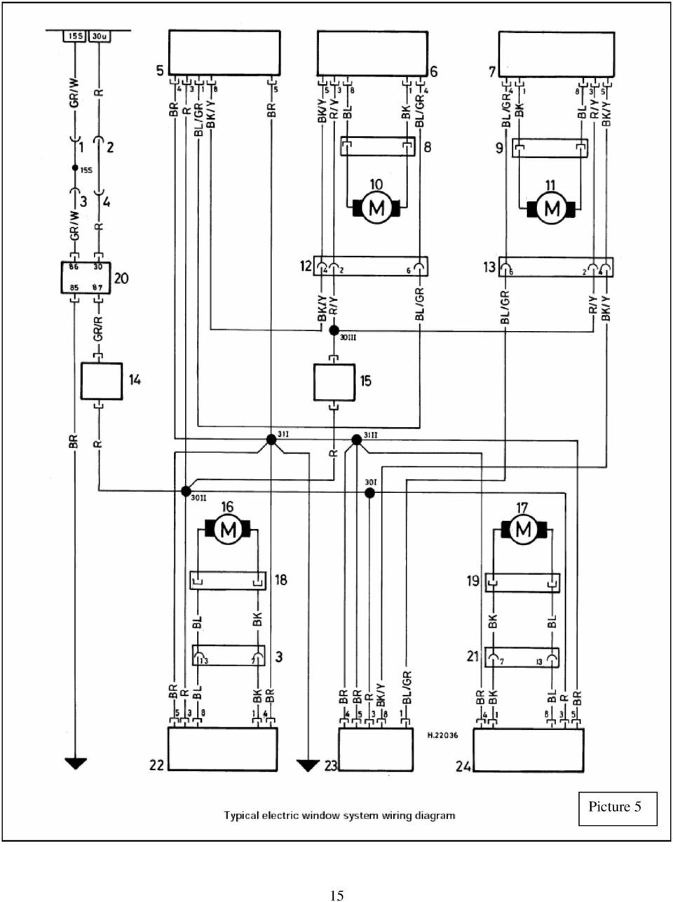
16 Key to electric window system wiring diagram (picture 5) 1. Plug for rear section to driver's door (5-pin) 2. Plug for rear section to center section (27 pin) 3. Plug for window control and central lock wire to driver's door(13- pin) 4. Plug for window control and central lock wire to special equipment plug 5. Window switch rear left 6. Window switch rear left 7. Window switch rear right 8. Plug for left rear door wire to window motor rear left 9. Plug for right door wire to window motor rear right 10. Wlndow motor rear left 11. Window motor rear right 12. Plug for window control and central lock wire to left rear door 13. Plug lor window control and central lock wire to right rear door(7- pin) 14. Power safety switch 15. Child safety switch 16. Window motor front left 17. Window motor front right 18. Plug for driver's door wire to window motor front left 19. Plug for passenger's door wire to window motor of passenger's door 20. Relay 21. Plug for window control and central lock wire to passenger's door (13-pin) 22. Wlndow switch front left 23. Window switch rear right 24. Window switch front right 16
 14. Power safety switch 15.")
17 17 Picture 6
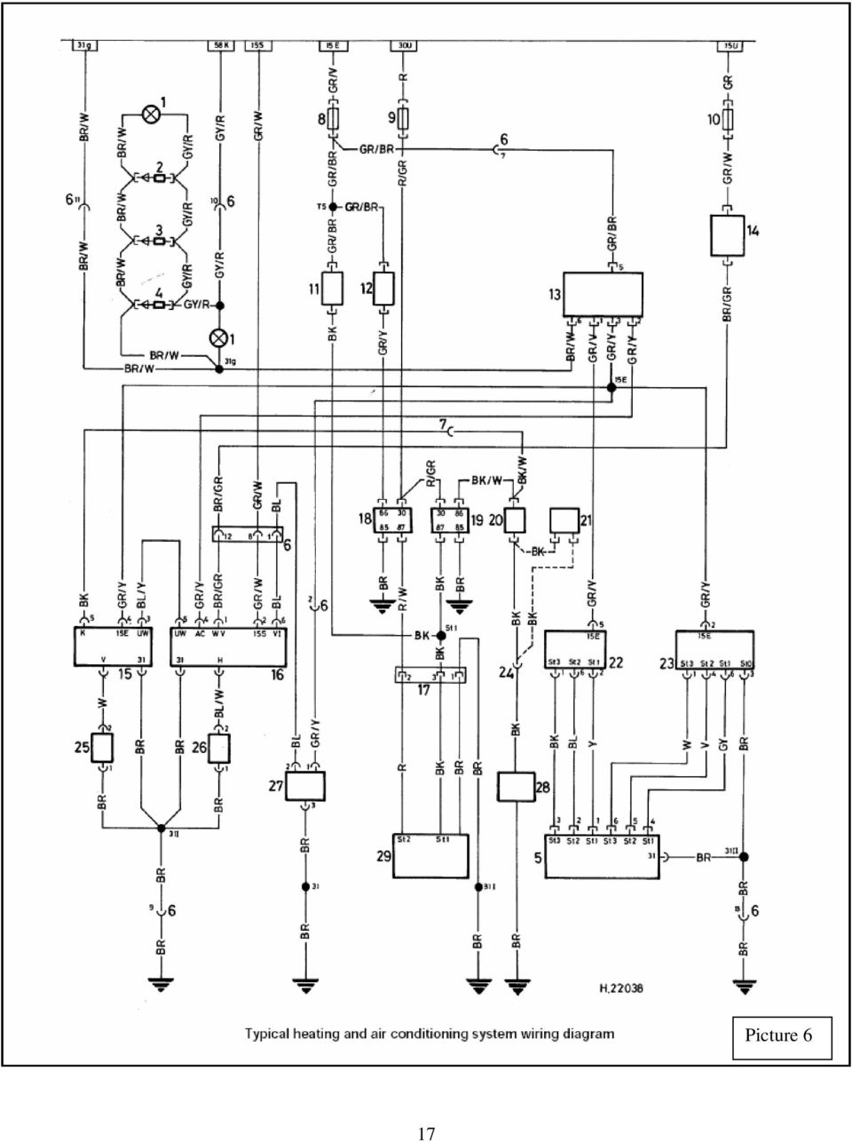
18 Key to air conditioning system wiring diagram (picture 6) 1. Light for heater controls 2. Light diode III 3. Light diode II 4. Light diode I 5. Switch - heater/evaporator blower 6. Plug heater control wire harness to centre wire harness (13-pin) 7. Plug - front wire harness section to heater controls 8. Fuse - heater blower 9. Fuse - extra fan stage II 10. Fuse - ind.lamp, reversing lights, tachometer and mirrors (power distributor) 11. Temperature switch 91 C - stage I 12. Temperature switch 99 C - stage II 13. Switch-airconditioner 14. Water valve 15. Evaporator temperature regulator 16. Air conditioner control unit (heater controls) 17. Plug - extra fan motor (on extra fan motor I) 18. Relay - extra fan stage II (on power distributori 19. Relay - extra fan stage I (on power distributori 20. Switch - high pressure pressostat (drier) 21. Switch temperature 110 C(only for 524td) 22. Motor-heater blower 23. Motor - evaporator blower 24. Plug - high pressure pressostat to electromagnetic coupling 25. Evaporator temperature sensor (in evaporator) 26. Heater temperature sensor (in heater) 27. Inside temperature sensor(lower trim panel left) 28. Eiectromagnetic coupling far compressor 29. Motor - extra fan 18
 17. Plug - extra fan motor (on extra fan motor I) 18. Relay - extra fan stage II (on power distributori 19.")
19 19 Picture 7
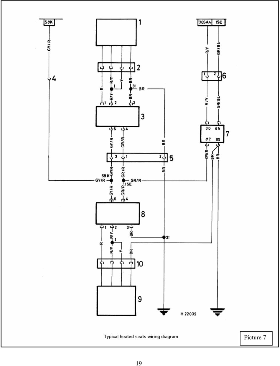
20 Key to wiring diagram for heated seats (picture 7) 1. Heating - passenger's seat 2. Seat heating connection pessenge s side 3. Seat heating switch - passenger's side 4. Plug far heated seat wire (driver's side) to special equipment plug (58K) 5. Plug for heated seat wire (driver s side) to passenger s side 6. Plug for heated seat wire (driver s side) to special equipment plug (15E and 30SA4) 7. Seat heating relay 8. Seat heating switch driver s side 9. Heating- driver s side 10. Seat heating connection driver s side 20
 to special equipment plug (15E and 30SA4) 7. Seat heating relay 8.")
21 21 Picture 8/1
22 22 Picture 8/2
23 Key to wiring diagram for memory power seats (picture 8/1 8/2) 1. Plug connection far special equipment plug 2. Plug connection of wire for passenger's seat 3. Plug connection of wire for seat control with memory 4. Connection of wire for seat control with memory 5. Seat control switch 6. Backrest 7. Slide 8. Headrest 9. Height front 10. Height rear 11. Plug connection for seat backrast/slide control 12. Plug connection for seat headrest control 13. Plug connection for seat height control 14. Electronic control unit (undermeath seat) 15. Plug connection of wire for seat control with memory 16. Plug connection of wire for seat with memory 17. Plug connection for seat control drive 18. Plug connection for memory switch 19. Plug connection for slide potentiometer 20. Plug connection for front height potentiometer 21. Plug connection for rear height potentiameter 22. Plug cannection for headrest motor 23. Plug connection for backrest potentiometer 24. Plug connection for backrest motor 25. Memory switch 26. Motor-seat backrest control 27. Motor headrest control 28. Motor-height control rear 29. Motor-height control front 30. Motor-slide 23
24 24 Picture 9
25 Key to wiring diagram for power seats without memory (picture 9) 1. Plug connection far special equipment plug 2. Backrest 3. Seat foward/backward 4. Headrest 5. Seat up/down front 6. Seat up/down read 7. Plug switch for backrast/seat control 8. Plug switch for headrest control 9. Plug switch for front/rear seat up/down control 10. Switch for power seats 11. Plug - power seal wire to power seat electronic control unit 12. Electronic control unit for power seats (below seats) 13. Plug - power seat drive to power seat electronic control unit 14. Plug - power backrest and headrest wire to power seat electronic control unit 15. Plug - power backrest and headrest wire to backrest motor 16. Plug - power backrest and headrest wire to the headrest motor 17. Plug - power seat wire on driver's side to wire on passenger's side 18. Motor-seat up/down front 19. Motor-seat up/down rear 20. Motor - seat forward/backward 21. Motor - backrest 22. Motor - headrest 25
26 26 Picture 10
27 1 Speaker door right 2 Speaker front right 3 Speaker rear right 4 Special equipment plug RA12 5 Connection for power windows 6 Amplifier 7 Speaker front left 8 Speaker door left 9 Connection for power supply lead IO Connection for power aerial 11 Radio 12 Speaker balance control 13 Speaker rear left Key to radio wiring diagram (picture 10) 27
28 28
Wiring diagrams 14 1. Component key for wiring diagrams 1 to 29 Note: Not all the items listed will be fitted to all models
 Wiring diagrams 14 1 Component key for wiring diagrams 1 to 29 Note: Not all the items listed will be fitted to all models No Description 00200 Alternator with built-in regulator 00500 Battery 01001 Starter
ELECTRICAL WIRING (R.H. DRIVE VEHICLES)
") C-1 ELECTRICAL WIRING (R.H. DRIVE VEHICLES) CONTENTS GENERAL.......................... 3 WIRING HARNESS CONFIGURATION DIAGRAMS......................... 4 ENGINE COMPARTMENT................ 4 DASH PANEL...........................
C-1 ELECTRICAL WIRING (R.H. DRIVE VEHICLES) CONTENTS GENERAL.......................... 3 WIRING HARNESS CONFIGURATION DIAGRAMS......................... 4 ENGINE COMPARTMENT................ 4 DASH PANEL...........................
Transporter Fitting Locations No. 804 / 1
 Page 1 of 10 Transporter Fitting Locations No. 804 / 1 Pin connector assigment of selected connections Overview: 1 - Ignition/starter switch -D- On steering column Connector assigment chapter 2 - Onboard
Subaru Reference. This reference contains the following information: connector pinouts. connector pinouts
 Subject: Source: 1993 2010 Impreza, WRX, and Sti and 2002 07 Outback Sport ABS wiring diagrams, harness routing, and connector locations and pinouts Subaru service manuals This reference contains the following
1993 WIRING DIAGRAMS Volkswagen Wiring Diagrams. Volkswagen; EuroVan
 Article Text ARTICLE BEGINNING 1993 WIRING DIAGRAMS Volkswagen Wiring Diagrams Volkswagen; EuroVan COMPONENT LOCATION MENU COMPONENT LOCATIONS TABLE ÄÄÄÄÄÄÄÄÄÄÄÄÄÄÄÄÄÄÄÄÄÄÄÄÄÄÄÄÄÄÄÄÄÄÄÄÄÄÄÄÄÄÄÄÄÄÄÄÄÄÄÄÄÄÄÄÄÄÄÄÄÄÄÄÄ
Transporter Current Flow Diagram No. 80 / 1
 Transporter Current Flow Diagram No. 80 / 1 2.5 l/65 kw direct injection turbo diesel, engine code AJT From May 1999 2.5 l/75 kw direct injection turbo diesel, engine codes ACV, AUF 2.5 l/111 kw direct
FZ400 1997-1998 WIRING DIAGRAM (JAPANESE MARKET FAZER 400) 5
 5") FZ400 1997-1998 WIRING DIAGRAM (JAPANESE MARKET FAZER 400) 5 1 2 4 7 6 11 12 13 13 12 13 3 13 8 9 56 14 59 52 54 15 48 55 34 22 16 51 50 60 47 46 36 35 23 17 49 24 25 18 44 37 38 39 40 58 33 26 27 28 29
FZ400 1997-1998 WIRING DIAGRAM (JAPANESE MARKET FAZER 400) 5 1 2 4 7 6 11 12 13 13 12 13 3 13 8 9 56 14 59 52 54 15 48 55 34 22 16 51 50 60 47 46 36 35 23 17 49 24 25 18 44 37 38 39 40 58 33 26 27 28 29
This file is available for free download at http://www.iluvmyrx7.com
 This file is available for free download at http://www.iluvmyrx7.com This file is fully text-searchable select Edit and Find and type in what you re looking for. This file is intended more for online viewing
G PART NUMBER OF CONNECTORS
 A 1 A/C Ambient Temp. Sensor 90980 11070 Buckle SW RH (w/ Power Seat) A/C Condenser Fan Motor (1G FE) 90980 10928 B 9 Buckle SW RH (w/o Power Seat) 90980 11212 A 2 A/C Condenser Fan Motor (2JZ GE) 90980
Jaguar XJ6 series 3 Schematic Drawings
 Jaguar XJ6 series 3 Schematic Drawings http://www.skjagtech.co.uk 1979-1986 Document date 15-May-2006 Contents Head, Side and Fog light Schematic 3 Headlamp wash wipe 4 Cruise Control 4 Wash wipe Reverse
Audi A4 No. 2/1. Standard Equipment. Wiring diagram. from 2002 m. y. Edition 08/01 W42.USA.5504.01.21. Main fuse
 Audi A4 No. / Standard Equipment fm 00 m. y. Main fuse A97--00 Connector station E-box, plenum chamber 4 5 6 7 A97--048 4-Pin Relay Carrier w ith threaded connection A B C D E F 4 G H A97--045 Edition
CIRCUIT DIAGRAMS GROUP 90 90-1 CONTENTS TAILLIGHT, POSITION LIGHT, REAR SIDE MAKER LIGHT, LICENSE PLATE LIGHT AND LIGHTING MONITOR TONE ALARM...
 90-1 GROUP 90 DIAGRAMS CONTENTS HOW TO READ DIAGRAMS.................... 90-4 ETACS-ECU.................... 90-10............. 90-14 CENTRALIZED JUNCTION........ 90-19 POWER DISTRIBUTION SYSTEM.. 90-26
Wiring diagram layout
 Wiring diagram layout 3 30 Relay panel Indicated by grey area. 500 0,0 WIRING COLOR CODE 00 D/50,5 / T0a/ ws = white = black = red br = bwn gn = green bl = blue gr = grey li = lilac ge = yellow bl T 4e/
Copyright 2002-2004 Triple S Customs
 CHEVROLET SILVERADO 1988-2005 VEHICLE WIRING Copyright 2002-2004 Triple S Customs WIRING INFORMATION: 1988 Chevy Silverado Full-Size 2- POWER DOOR LOCK (5-wire reverse polarity) POWER DOOR UNLOCK (5-wire
Wynn s Extended Care
 Wynn s Extended Care Every car deserves to receive the very best care... especially yours. How Do You Keep Your Reliable Transportation Reliable? Count on Wynn s Because Wynn s has been caring for cars
6-years/75,000 miles Comprehensive coverage Subsequent Owner Warranty $100 Deductible
 LINCOLN PREMIER LIMITED WARRANTY 6-years/75,000 miles Comprehensive coverage Subsequent Owner Warranty $100 Deductible Comprehensive Coverage Because Lincoln has always been a brand you can trust and respect,
Touareg Component Locations No. 802 / 1
 Touareg Component Locations No. 802 / 1 1 Fuses 1.1 Fuses 1.1.1 Overview of Fuses 1 - Fuses (SB) on fuse panel B on left instrument panel Location page 3 Fuse Arrangements, from November 2006 page 4 2
Power Door Locks Cruise Control System. Cigarette Lighter. Blower. Fan. Windshield Wiper System. See Note. High Wiper. Med. Low.
 + + Power Door Locks Cruise Control System Cigarette Lighter Power Windows Blower Fan Windshield Wiper System Clock Radio Rev. Light Switch See Note HVAC Side Marker Light Park/Turn Signal Low/High Beam
BODY ELECTRICAL TOYOTA ELECTRICAL WIRING DIAGRAM WORKBOOK. ASSIGNMENT Version 1.8 WORKSHEETS. http://www.autoshop101.com
 BODY ELECTRICAL ASSIGNMENT Version 1.8 WORKSHEETS TOYOTA ELECTRICAL WIRING DIAGRAM WORKBOOK http://www.autoshop101.com Developed by Kevin R. Sullivan All Rights Reserved TOYOTA Table of Contents Wiring
Vehicle electrics in Polo Model Year 2002
 Service. Self-Study Programme 265 Vehicle electrics in Polo Model Year 2002 265_061 The range of electrical systems in new vehicles is expanding increasingly as a result of the ever more effective safety
HONDA ACCORD 1985-2005
 HONDA ACCORD 1985-2005 VEHICLE WIRING Copyright 2002-2004 Triple S Customs WIRING INFORMATION: 1985 Honda Accord WIRE WIRE COLOR WIRE LOCATION 12V CONSTANT WHITE or WHITE/BLACK Ignition Harness STARTER
2009 QUICK REFERENCE GUIDE GET INFORMED. ROLL.
 xb 2009 QUICK REFERENCE GUIDE GET INFORMED. ROLL. 2009 Scion xb This Quick Reference Guide is a summary of basic vehicle operations. It contains brief descriptions of fundamental operations so you can
INTRODUCTION CONTENTS
 1 INTRODUCTION This booklet contains Wiring Diagrams for 1979 vehicles listed in the contents below. All diagrams contained in this booklet are based on the latest product information available at the
HOW TO READ THE WIRING DIAGRAMS
 A-1 HOW TO READ THE WIRING DIAGRAMS CONTENTS COMPOSITION AND CONTENTS OF WIRING DIAGRAMS... 2 HOW TO READ CONFIGURATION DIAGRAMS... 3 MARKING FOR CONNECTOR EARTHING... 6 WIRE COLOUR CODES... 9 ABBREVIATION
Parts and Accessories. Installation Instructions.
 Parts and Accessories. Installation Instructions. Rear-view camera retrofit MINI ONE (R 50) MINI COOPER (R 50) MINI COOPER S (R 53) These installation instructions are only valid for cars with SA 609 (navigation
A/C-HEATER SYSTEM - AUTOMATIC
 A/C-HEATER SYSTEM - AUTOMATIC 1995 Volvo 850 1995-96 Auto. A/C-Heater Systems Volvo 850 * PLEASE READ THIS FIRST * WARNING: To avoid injury from accidental air bag deployment, read and carefully follow
BODY ELECTRICAL MAZDA
 BODY ELECTRICAL ASSIGNMENT WORKSHEETS Version 1.3 MAZDA ELECTRICAL WIRING DIAGRAM WORKBOOK http://www.autoshop101.com Developed by Kevin R. Sullivan All rights reserved. MAZDA Table of Contents Wiring
2007 W-SERIES (CHEVROLET & GMC) N-SERIES (ISUZU) 250 NPR/W3500, NPR HD/W4500, NQR/W5500, NRR/W5500-HD Diesel Electrical Symbols
 N-SERIES (ISUZU) 250 NPR/W3500, NPR HD/W4500, NQR/W5500, NRR/W5500-HD Diesel Electrical Symbols") 2007 W-SERIES (CHEVROLET & GMC) N-SERIES (ISUZU) 250 NPR/W3500, NPR HD/W4500, NQR/W5500, NRR/W5500-HD Diesel Electrical Symbols Symbol Meaning Symbol Meaning Symbol Meaning Fuse Electronic Parts Coil (Inductor),
2007 W-SERIES (CHEVROLET & GMC) N-SERIES (ISUZU) 250 NPR/W3500, NPR HD/W4500, NQR/W5500, NRR/W5500-HD Diesel Electrical Symbols Symbol Meaning Symbol Meaning Symbol Meaning Fuse Electronic Parts Coil (Inductor),
510351 92970196 instruction rev 0.0 11/13/2012
 INSTRUMENT LUSTER ISNET AESSORY NETOR INITION Sheet 2 FLOOR IMMER WIPER PA AS ROUN LEFT AN RIT AN ELETRI SPEEO ROUN ORN RELAY TURN SINAL PARIN BRAE NEUTRAL SAFETY EALIT BRAE RAIO IARETTE LITER BA UP INSTALLIN
Air conditioning, electrical testing
 just a test. Air conditioning, electrical testing 01-253 Wire and component test using VAG1598 A test box Special tools and equipment VAG 1598 A test box and VAG 1598/11 adapter cable and VAG 1598/12 VAG1526
MULTIPLEXED BSI OPERATING PRINCIPLE FOR THE XSARA PICASSO AND XSARA CITROËN UK LTD 221 BATH ROAD SLOUGH SL1 4BA
 CITROËN TECHNICAL TRAINING MULTIPLEXED BSI OPERATING PRINCIPLE FOR THE XSARA PICASSO AND XSARA CITROËN UK LTD 221 BATH ROAD SLOUGH SL1 4BA DEALER PERSONNEL DEVELOPMENT AND TRAINING CITROËN UK LTD. Reproduction
WIRING HARNESS FOR AS635P4. BLUE PLUG RED, BLUE, BLACK, WHITE - Plug in dual stage sensor harness
 WIRING HARNESS FOR AS635P4 ANTENNA NOT USED 5 PIN WHITE PLUG 2 PIN WHITE PLUG GREEN - PARKING BRAKE INPUT (-) BLUE - NOT USED 3 PIN BLUE PLUG RED, BLUE, BLACK, WHITE - Plug in dual stage sensor harness
1R / 4-BUTTON SERIES
 Button 1 1R / 4-BUTTON SERIES VEHICLE SECURITY SYSTEM Standard Features: Two 4-Button Remote Transmitters Status indicator (LED) Valet / override switch Multi-tone siren Dual stage impact detector Remote
INSTRUMENT PANEL. 1995 Volvo 850 DESCRIPTION & OPERATION. 1995-96 ACCESSORIES & EQUIPMENT Volvo Instrument Panels
 INSTRUMENT PANEL 1995 Volvo 850 1995-96 ACCESSORIES & EQUIPMENT Volvo Instrument Panels 850 WARNING: When working around steering column and before performing repairs, disconnect and shield battery ground
Table of Contents. Introducing AYGO. Accessing your vehicle 2 3. Lights 9. Wipers 10. Electric windows 4. Gear change 11
 AYGO Brief Guide Table of Contents Accessing your vehicle 2 3 Electric windows 4 Steering wheel (Vehicles with an adjustable type) 4 Seat and seat belt adjustment 5 Instrument Panel overview 6 Instrument
E T K A 14:36 18.02.20100 970-00. Year. Illustration. Model. Seite: 001. et_bt1.frm. Pos Part Number Name Remarks Qty Model.
 0 7 70-00 4:36 8.02.2000 connector housing pin 05 05 37 diode connector 2 3 4 5 6 2 05 05 37 D diode connector 7 8 0 2 3 4 5 6 7 8 20 2 22 23 24 25 26 27 28 2 30 3 32 33 34 3 357 07 7 B terminal pin housing
1970-72 Chevelle. 1970-72 Chevelle. (500645) Gauge Cluster Kit Installation Instructions. (500645) Gauge Cluster Kit Installation Instructions
 Gauge Cluster Kit Installation Instructions. (500645) Gauge Cluster Kit Installation Instructions") 1970-72 Chevelle (500645) Gauge Cluster Kit Installation Instructions 1970-72 Chevelle (500645) Gauge Cluster Kit Installation Instructions STEP 1: There are 4 small gauges. This is a photo of the bare
1970-72 Chevelle (500645) Gauge Cluster Kit Installation Instructions 1970-72 Chevelle (500645) Gauge Cluster Kit Installation Instructions STEP 1: There are 4 small gauges. This is a photo of the bare
1978-83 Malibu 1978-87 Monte Carlo 1978-87 El Camino
 Important facts about this kit. 1. The dash panel used in this picture is used by permission of Covan's Classic. 2. This kit requires some modification to your original under dash wiring harness. It is
Porsche Approved Certified Pre-Owned. Limited Warranty
 Porsche Approved Certified Pre-Owned Limited Warranty Porsche Approved. A guaranteed mark of quality. At Porsche, we re committed to exceptional performance. The inherent reliability and longevity of
INSTALLATION MANUAL 3RP / 5RP 4-BUTTON SERIES VEHICLE SECURITY SYSTEMS
 3RP / 5RP 4-BUTTON SERIES VEHICLE SECURITY SYSTEMS INSTALLATION MANUAL Before you begin the installation Read the INSTRUCTIONS! Always use a multi-meter when verifying vehicle wiring. Before mounting the
KEYLESS ENTRY UPGRADE SECURITY SYSTEM for 2004 TOYOTA HIGHLANDER
 KEYLESS ENTRY UPGRADE SECURITY SYSTEM for 2004 TOYOTA HIGHLANDER DEALER SERVICE AND INSTALLATION MANUAL KIT NO. 00016-30915 Contents PARTS LIST... 2 PARTS ILLUSTRATIONS... 2 VEHICLE PREPARATION... 3 INSTALLING
Scion xb. Pocket Reference Guide. <http://www.scion.com/>, Contact
 EMAIL US , Contact 2006 CHAT On weekdays you can chat with a Scion Customer Advocate. , Have a Question? or Contact CALL US For the Scion Customer Experience
CONTINUED COVERAGE FOR YOUR NEW, USED, OR CERTIFIED PRE-OWNED BMW.
 BMW EXTENDED SERVICE CONTRACTS FEEL THE RUSH OF ASSURANCE. CONTINUED COVERAGE FOR YOUR NEW, USED, OR CERTIFIED PRE-OWNED BMW. Whether your original 4-year/50,000-mile BMW Warranty is coming to an end,
The Touareg Electrical System
 Service. Self-Study Programme 298 The Touareg Electrical System Design and Function Vehicles with off-road capability are no longer just utility vehicles for a limited group of people. At all levels in
specializing in AIR CONDITIONING, PARTS AND SYSTEMS for your classic vehicle PERFECT FIT IN-DASH HEAT/ COOL/ DEFROST 1967-72 CHEVROLET PICKUP
 specializing in AIR CONDITIONING, PARTS AND SYSTEMS for your classic vehicle PERFECT FIT IN-DASH HEAT/ COOL/ DEFROST 1967-72 CHEVROLET PICKUP CONTROL & OPERATING INSTRUCTIONS The controls on your new Perfect
356 CHECKLIST ELECTRICAL: CHASSIS:
 356 CHECKLIST ELECTRICAL: Headlights hi/lo beam Taillights Running lights Turn signals Brake lights License light(s) Fog lights Reverse light Horn Dome lights Dash lights Temp guage Tank level guage Tachometer
Headlight switch. The daytime running. lights) turn on.
 turn on.") Headlight switch The headlights can be operated manually or automatically. U.S.A. Canada The daytime running lights turn on The side marker, parking (vehicles with halogen headlights), daytime running
Headlight switch The headlights can be operated manually or automatically. U.S.A. Canada The daytime running lights turn on The side marker, parking (vehicles with halogen headlights), daytime running
AUTOMOBILE MECHANIC STUDENT INTERNSHIP SKILLS LIST Provo School District
 AUTOMOBILE MECHANIC STUDENT INTERNSHIP SKILLS LIST Provo School District Repairs and overhauls automobiles, buses, trucks, and other automotive vehicles: Examines vehicle and discusses with customer or
ISUZU RODEO 1992-2003
 ISUZU RODEO 1992-2003 VEHICLE WIRING Copyright 2002-2004 Triple S Customs WIRING INFORMATION: 1992 Isuzu Rodeo 12V CONSTANT WIRE BLACK Ignition Harness STARTER WIRE WHITE/BLUE OR BLACK/WHITE Ignition Harness
MINI EXTENDED SERVICE CONTRACTS
 MINI EXTENDED SERVICE CONTRACTS LESS WORRY, MORE WEEEE! CONTINUING COVERAGE FOR YOUR NEW, USED, OR CERTIFIED PRE-OWNED MINI. Whether your odometer is ticking toward the end of your original 4-year/50,000-mile
Multi Function, User Configurable Remote Vehicle Security System with 4 Button Replaceable Membrane Remote Transmitter
 MODEL PRO-9744 INSTALLATION MANUAL Multi Function, User Configurable Remote Vehicle Security System with 4 Button Replaceable Membrane Remote Transmitter This System Allows The Transmitter Buttons To Be
FUSE BOARD IN DRIVER S FOOTWELL
 FUSE BOARD IN DRIVER S FOOTWELL COLOUR VALUE PORSCHE NUMBER LIGHT BROWN 5.0 A 999.607.004.00 BROWN 7.5 A 999.607.005.00 BLUE 15 A 999.607.007.00 WHITE 25 A 999.607.009.00 GREEN 30 A 999.607.010.00 ORANGE
Audi A3 Audi A3 Sportback Quick reference guide
 Audi A Audi A Sportback Quick reference guide Dear Audi Driver, This quick reference guide gives you a brief introduction to the main features and controls of your vehicle. However, it cannot replace the
SECTION 1-5 OPERATION OF INSTRUMENTS AND CONTROLS 06.0.711. Lights, Wipers and Defogger
 OPERATION OF INSTRUMENTS AND CONTROLS Lights, Wipers and Defogger SECTION 1-5 Headlights and turn signals................................... 76 Emergency flashers..........................................
Standard Equipment. 2002 m. y. Fuse Panel. Micro Central Electric Panel A B C. 13 - Fold Relay Panel. Edition 05/01 W42.USA.5702.07.
 Audi TT No. 5/ Standard Equipment 00 m. y. Fuse Panel 8 6 0 5 9 3 7 3 6 0 4 8 4 7 9 3 4 38 Res 5 3 39 Res 6 33 40 Res 7 34 4 Res 8 35 4 Res 9 36 43 37 44 A97--09 Fuse Colors: A - Green 5 A - White 0 A
Extended Protection Plans for New and Pre-Owned Vehicles
 Extended Protection Plans for New and Pre-Owned Vehicles Protection from the Unexpected. Your vehicle is not only an investment; it s your transportation lifeline. Driver s Choice from Old Republic Insured
Toyota Extra Care Platinum
 Toyota Extra Care Platinum Vehicle Service Agreement Backed by the Strength and Stability of Toyota What is a Vehicle Service Agreement? VSAs cover the cost of mechanical breakdowns beyond your vehicle
Extended Protection Plans for New and Pre-Owned Vehicles
 Extended Protection Plans for New and Pre-Owned Vehicles Extended Protection you can count on from Old Republic Insured Automotive Services, Inc. (ORIAS) Your vehicle is a major investment. Next to your
MOTOR VEHICLE MECHANIC REPAIR CATEGORIES
 Chapter 8: Motor Vehicle Mechanic Repair Categories Page 1 CHAPTER 8 MOTOR VEHICLE MECHANIC REPAIR CATEGORIES Section 8-1 REQUIREMENT Section 10 of the Motor Vehicle Service and Repair Act (MCL 257.1310)
PUSH BUTTON START INSTALLATION MANUAL
 PUSH BUTTON START INSTALLATION MANUAL ALTHOUGH THIS PRODUCT HAS BEEN THOROUGHLY TESTED KPIERSON TECHNOLOGIES ASSUMES NO RESPONSIBILITY FOR ANY DAMAGE THAT MAY RESULT BY THE INSTALLATION OF THIS PRODUCT.
4 Star 4 Star Plus. Vehicle
 4 Star 4 Star Plus Vehicle Service Contracts WARRANTY SOLUTIONS Experience you can rely on Throughout our history, Warranty Solutions has demonstrated strength and versatility while evolving through ever-changing
HEATER, AIR CONDITIONING AND VENTILATION
 55-1 GROUP 55 HEATER, AIR CONDITIONING AND VENTILATION CONTENTS GENERAL DESCRIPTION 55-2 HEATER AND AIR CONDITIONING SYSTEM 55-4 HEATER CONTROL 55-6 A/C-ECU 55-7 A/C COMPRESSOR 55-9 CONDENSER 55-9 DUCT
Copyright 2002-2004 Triple S Customs
 JEEP GRAND CHEROKEE 1992-2006 VEHICLE WIRING Copyright 2002-2004 Triple S Customs WIRING INFORMATION: 1992 Jeep Grand Cherokee 12V CONSTANT WIRE PINK/BLACK or RED/WHITE Steering Column STARTER WIRE YELLOW/BLUE
Parts and Accessories. Installation Instructions.
 Parts and Accessories. Installation Instructions. High on-board computer retrofit BMW 5 Series (E39) BMW X5 (E53) Retrofit kit No. 65 90 0 308 455 Installation time The installation time is approx,0 -,5
01-3 0000-00 6810-20 AIR CONDITIONING SYSTEM 1. FFH SPECIFICATION AIR CONDITIONING SYSTEM RODIUS 2004.09
 0000-00 01-3 6810-20 1. FFH SPECIFICATION 01-4 0000-00 2. SYSTEM LAYOUT AND COMPONENTS 0000-00 01-5 01-6 0000-00 3. FFH GENERAL INFORMATION The system is to increase the coolant temperature quickly by
The Crafter Electrical system
 Service Training Self-study Programme 370 Commercial Vehicles The Crafter Electrical system Design and function Innovations in automotive engineering are also taking place in the commercial vehicle segment.
BMW Parts and Accessories Installation Instructions
 BMW Parts and Accessories Installation Instructions Retrofit Anti-theft Alarm System (DWA) series-identical retrofit for BMW 5 Series saloon and touring (E 9, E 9/) left-hand drive F 9 005 W Installation
Operating manual L / XL / XXL 212 Facelift
 Operating manual L / XL / XXL 212 Facelift +49 (0)2058 89 80-0 www.rappold-karosserie.de [email protected] 0 +49 (0)2058 89 80-0 www.rappold-karosserie.de [email protected] 1 Table of
SECTION 2 3 OPERATION OF INSTRUMENTS AND CONTROLS. Lights, Wipers and Defogger
 OPERATION OF INSTRUMENTS AND CONTROLS Lights, Wipers and Defogger SECTION 2 3 Headlights and turn signals................................... 92 Emergency flashers..........................................
COVERING MILLIONS Preferred Protection Plan, a Service Group Company www.sgifs.com PO Box 26830, Austin, TX 78755-0800.
 COVERING MILLIONS Preferred Protection Plan, a Service Group Company www.sgifs.com PO Box 26830, Austin, TX 78755-0800. 1-877-565-0816 PPP-308 0903 rev 0408 BENEFITS New and Pre-Owned Vehicles Preferred
Diagnosing and Understanding Starting Problems on the ZR-1 Marc Haibeck 28-Sep-13
 Diagnosing and Understanding Starting Problems on the ZR-1 Marc Haibeck 28-Sep-13 There are three basic failure conditions: - A VATS security system lockout - A click from the starter solenoid but no engine
Section 7. Evaporator thermistor. Under-and-over pressure safety switches. Connections to the ECU
 Automatic Temperature Control Diagnosis and Repair Diagnosis of Automatic A/C Systems The most common automatic A/C system malfunctions tend to be the result of basic air conditioning problems. These problems
SECURITY SYSTEM ADP-CAN
 INSTALLATION INSTRUCTION SECURITY SYSTEM ADP-CAN Introduction Motorcar security system ADP-CAN is for motorcars provided with CAN net. It is for the work with the motorcar factory security systems or remote
The Child Reminder System Installation Manual
 The Child Reminder System Installation Manual Revised June, 2006 Detailed installation information can be found at www.childreminder.com. Get through your installation quickly and easily by calling 1-888-330-6786
2017 Audi Maintenance Schedule - All Models
 2017 Audi Maintenance Schedule - All Models MY 2017 Maintenance Intervals - USA Service Intervals If you are not sure when you should bring your Audi in for service or which services are to be performed
Model 124 Relay and Control Modules Locations. 00-B.2a
 00-B.2a Page No. Fig. No. K1/2 Overvoltage protection relay (87E/87L/30a, 9-pole) B.2/2 1 K2 Headlamp washer relay B.2/1 K3/1 Intake manifold preheater relay B.2/4 14 K5 Power seat relay B.2/1 K9 Auxiliary
Ell STEERING COLUMN CONTROLS STEERING COLUMN CONTROLS
 STEERING COLUMN CONTROLS Ignition Switch........ 2-1 LightinglTurn Signal Control Lever... 2-5 Windshield Wiper and Washer Lever... 2-6 Rear Window Wiper/Washer Switch (if equipped)... 2-8 Tilt Steering
ABS- 0011 Left front wheel sensor Faulty signal. ABS- 0012 Left front wheel sensor Faulty signal. ABS- 0022 Right front wheel sensor.
 ABS- 0010 Left front wheel sensor Signal missing. Permanent fault ABS- 0011 Left front wheel sensor Faulty signal ABS- 0012 Left front wheel sensor Faulty signal ABS- 0020 Right front wheel sensor. Signal
AUTOMATIC CONTROL HEATING, VENTILATION AND AIR CONDITIONING SYSTEM
 SECTION 7D AUTOMATIC CONTROL HEATING, VENTILATION AND AIR CONDITIONING SYSTEM TABLE OF CONTENTS Description and Operation... 7D- General... 7D- FATC Control... 7D- FATC Input/Output Routing Diagram...
2015 Scion tc Quick Reference Guide
 2015 Scion tc Quick Reference Guide 2015 Scion tc This Quick Reference Guide is a summary of basic vehicle operations. It contains brief descriptions of fundamental operations so you can locate and use
VS Commodore LPG installation utilising an LPG Memcal and Apexus Quick-kit.
 VS Commodore LPG installation utilising an LPG Memcal and Apexus Quick-kit. Description of the components and operation LPG/Petrol changeover switch The LPG change-over switch is mounted in the instrument
Left Hand Limit Switch. Housing. Left Hand. Connections. Motor Connector BROWN PURPLE GRAY BLACK DARK BLUE BLACK BROWN BROWN LIGHT BLUE.
 LIGHT BLUE GRAY PURPLE Circuit Breaker Intput Circuit Breaker Output #1 Relay Left Hand Limit Switch Housing Left Hand Motor Connector Right Hand Limit Switch on Radiator Support Right Hand Limit Switch
BR150 Pmi Baja Reaction 150cc Go Kart (VIN PREFIX L4VM)
") Page 1 of 21 Product Information Baja Web > Product Information > Parts Lists > GOKART > BR150 Pmi Baja Reaction 150cc Go Kart (VIN PREFIX L4VM) BR150 Pmi Baja Reaction 150cc Go Kart (VIN PREFIX L4VM)
Page 1 of 21 Product Information Baja Web > Product Information > Parts Lists > GOKART > BR150 Pmi Baja Reaction 150cc Go Kart (VIN PREFIX L4VM) BR150 Pmi Baja Reaction 150cc Go Kart (VIN PREFIX L4VM)
INSTALLATION INSTRUCTIONS
 INSTALLATION INSTRUCTIONS Accessory Application Publications No. AII23628 2003 PILOT Issue Date MAY 2002 PARTS LIST Security System Kit (sold separately): P/N 08E51-S84-100 2 Remote controls Attachment
Third Edition. 1970-72 Corvette Technical Information Manual & Judging Guide Index
 Third Edition 1970-72 Corvette Technical Information Manual & Judging Guide Index Index INTERIOR Page 3 1. Upholstery and Seat Belts Page 5 1.1. Vinyl Upholstery Page 5 1.2. Custom (Leather) Upholstery
Mercedes-Benz Vito. Specifications
 Mercedes-Benz Vito Specifications Mercedes-Benz Technical Data Panel Van Specification Body Style Rated output (kw @ rpm) Max torque (Nm @ rpm) Injection Fuel consumption 1 (litres/100km) Front axle load
Technical Notes and Workshop Reference.
 Technical Notes and Workshop Reference. This reference file has been built up over the last twelve years at Piaggio Ltd, To help with fault finding, assembly understanding and to clarify and expand on
Schematic - 379 Model Family Electrical P94-6023 C 01
 Schematic - 379 Model Family Electrical P94-6023 C 01 SH NO. TITLE 1) INDEX 2) ARCHITECTURE 85) ENGINE - CUM ISX ( BJ SERVICES ) ( CONTINUED ) 3) LOCATION OF MAJOR COMPONENTS 86) ENGINE ECU POWER 4) LOCATION
Multi-information Display (see MID )
") Driving Position Memory (see Seats ) Power Mirrors (see Mirrors ) Indicators/Gauges (see Instrument Panel ) Multi-information Display (see MID ) HomeLink (see HomeLink ) Navigation System (see Navigation
Driving Position Memory (see Seats ) Power Mirrors (see Mirrors ) Indicators/Gauges (see Instrument Panel ) Multi-information Display (see MID ) HomeLink (see HomeLink ) Navigation System (see Navigation
Electrical Systems - IQAN Digital Control System. IQAN Control System Components... 5.1.3
 Section 5.1 Electrical Systems - IQAN Digital Control System IQAN Control System Components........................... 5.1.3 IQAN Operational Description: At Machine Startup.....................................
INSTALLATION MANUAL INSIDE ENGINE COMPARTMENT ZZT22#R (1ZZ-FE / 3ZZ-FE) / AZT220R (1AZ-FE) FOR EUROPEAN SPEC. AIR CONDITIONING ENGLISH.
 / AZT220R (1AZ-FE) FOR EUROPEAN SPEC. AIR CONDITIONING ENGLISH.") HFC 134a Ozone Friendly Refrigerant ZZT22#R (1ZZ-FE / 3ZZ-FE) / AZT220R (1AZ-FE) FOR EUROPEAN SPEC. AIR CONDITIONING ENGLISH AAAMU-63 INSIDE ENGINE COMPARTMENT INSTALLATION MANUAL 2000 (EUROPE) B.V.. All
HFC 134a Ozone Friendly Refrigerant ZZT22#R (1ZZ-FE / 3ZZ-FE) / AZT220R (1AZ-FE) FOR EUROPEAN SPEC. AIR CONDITIONING ENGLISH AAAMU-63 INSIDE ENGINE COMPARTMENT INSTALLATION MANUAL 2000 (EUROPE) B.V.. All
2006 Volkswagen Maintenance Schedule by Miles/Kilometers
 2.0 Liter Engine: Engine: Change engine oil and oil filter Engine: Check for leaks Service interval display: Reset (Where applicable) Exhaust system: Check for damage & leaks Battery: Check Door check
TOYOTA ELECTRONIC TRANSMISSION CHECKS & DIAGNOSIS
 Checks and Adjustments The transmission requires regular maintenance intervals if it is to continue to operate without failure. As we discussed in previous sections, transmission fluid loses certain properties
Heater and Air Conditioner, Blend Air System, Troubleshooting 83.06
 A/C Performance Diagnosis Problem Warm Airflow When the Air Conditioner is On, A/C Not Working, or Poor A/C Performance (dash outlet temperature is too high) Problem Warm Airflow When the Air Conditioner
xd 2010 QUICK REFERENCE GUIDE GET INFORMED. ROLL.
 xd 2010 QUICK REFERENCE GUIDE GET INFORMED. ROLL. 2010 Scion xd This Quick Reference Guide is a summary of basic vehicle operations. It contains brief descriptions of fundamental operations so you can
Parts and Accessories Installation Instructions
 Parts and Accessories Installation Instructions R5 5 Z CD changer retrofit kit MINI (R 5 and R 53) LHD and RHD The installation time is approx..5 hours, but this may vary depending on the condition of
Service Packages & Pricing
 Service Packages & Pricing Silver Gold Motorcycle Service Packages Change oil & filter Change oil & filter Fuel system treatment $ 109.95 $ 129.95 Platinum Replace spark plugs Change oil & filter Fuel
Introduction... 2. Body Specifications... 3. Technical Data... 4. Body... 5. Interior Rear Seats... 6. Center Arm Rest... 7. Child Seat Restraint...
 Table of Contents Subject Page Introduction.......................................... 2 Body Specifications.................................... 3 Technical Data........................................
PROCEDURES FOR SELF DIAGNOSTICS
 PROCEDURES FOR SELF DIAGNOSTICS Baum Tools Unlimited Inc. March 31, 1999 TAU 2.1 READING ACTUAL VALUES 1. Remove the operating console from the TAU 2. At the upper side of the operating consol there is
CDS TROUBLESHOOTING SECTION I. VACUUM. 1.0. Weak vacuum at wand. Gauge reads normal (10hg to 14hg)
") CDS TROUBLESHOOTING SECTION I. VACUUM 1.0. Weak vacuum at wand. Gauge reads normal (10hg to 14hg) 1.1. Clogged hoses or wand tube. Disconnect hoses and carefully check for an obstruction. 1.2. Excessive
CDS TROUBLESHOOTING SECTION I. VACUUM 1.0. Weak vacuum at wand. Gauge reads normal (10hg to 14hg) 1.1. Clogged hoses or wand tube. Disconnect hoses and carefully check for an obstruction. 1.2. Excessive