OWNER S MANUAL BBQ070
|
|
|
- Oswald Powers
- 7 years ago
- Views:
Transcription
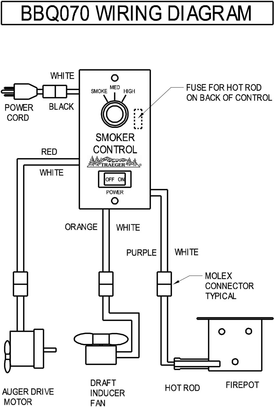
1 OWNER S MANUAL BBQ070 RESIDENTIAL PELLET GRILL This Grill Protected Under Patent Number: 4,823,684 FOR OUTDOOR USE ONLY! WARNING! DO NOT STORE OR USE COMBUSTABLE MATERIALS NEAR THIS APPLIANCE! USE ONLY TRAEGER BRAND HARDWOOD BBQ PELLETS IN THE OPERATION OF THIS UNIT.

2
3

4 INTRODUCTION Congratulations on your purchase of this Traeger Wood Pellet Grill, Model BBQ070. With proper set-up, operation and maintenance, the Grill will provide you with delicious food and years of cooking enjoyment. NOTE: NUMBERS FOLLOWING PART NAMES THROUGHOUT THIS MANUAL REFER TO THE COMPONENT DIAGRAM. When you un-box the Grill, remove all parts from the box and inside the Grill. Remove any remaining packaging material from inside the Grill as well. Make sure you have, and can identify all of the following parts: (1) Grill (2) (1) Hopper / Burner Assembly (31) (2) Legs (122) (2) Wheel Legs (127) (1) Porcelain Grill (166) (1) Grease Drain Pan (161) (1) Heat Baffle (157) (1) Smoke Stack (136) (1) Chimney Cap Assembly (138) (1) Chrome Door Handle (164) (1) Grease Bucket (135) (1) Hardware Kit (145) You will need to complete the assembly which includes: 1) Mounting the Legs (122) and Wheel Legs (127) to the Grill. 2) Installing the Hopper / Burner Assembly (31). 3) Attaching the Chrome Door Handle (164) to the Door (102). 4) Attaching the Smoke Stack (136) to the Grill. 5) Mounting the Chimney Cap Assembly (138). 6) Positioning the Heat Baffle (157) over the Firepot (72). 7) Positioning the Grease Drain Pan (161) over the Heat Baffle (157). 8) Positioning the Porcelain Grill (166) on the Grill Supports. 7) Hanging the Grease Bucket (135). TOOLS ARE SUPPLIED FOR ASSEMBLY (2) Open end wrenches (1) Hex key (Allen Wrench) Follow these step-by-step instructions and you ll be cookin in no time!

5 SECTION ONE: ASSEMBLY INSTRUCTIONS MOUNTING THE LEGS: 1) Carefully lay the Grill on its back on a non-abrasive surface. 2) Use the Black Bolts, Washers and Nuts (see Detail A ) supplied in the Hardware Kit (145) to install the Legs (122) on the left end of the Grill and the Wheel Legs (127) on the right end as shown in the diagram below. The Acorn Nuts (133) on the Wheel Legs (127) should go toward the center of the Grill. Leave the Nuts loose during this step. 3) Set the Grill upright to level and then tighten all Nuts.
 on the Wheel Legs (127) should go toward the center of the Grill. Leave the Nuts loose during this step.")
6 INSTALLING THE HOPPER / BURNER ASSEMBLY: NOTE: Do not remove the white, square Burner Gasket (90) from the Hopper/Burner Assembly (31). 1) Slide the Hopper / Burner Assembly (31) into the square opening on the left end of the Grill. Gently push the Hopper / Burner Assembly (31) into the Grill until the Burner Gasket (90) fits snugly against the left end. 2) Align the Nut Serts in the Hopper / Burner Assembly (31) with the bolt holes in the Grill. 3) Place Zinc Flat Washers on four of the 3/4 long Hex Head Bolts. Insert the Bolts into the Nut Serts from inside the Grill and tighten. Do not over tighten. ATTACHING THE CHROME DOOR HANDLE: 1) Insert the threaded studs on the Chrome Door Handle (164) through the slots in the Door (102). 2) Place a Zinc Flat Washer, then a Zinc Lock Washer on each threaded stud. Secure with Hex Nuts using the Wrench supplied. Do not over tighten. ATTACHING THE SMOKE STACK AND CHIMNEY CAP ASSEMBLY: 1) Align the holes in the Smoke Stack (136) with the holes in the Smoke Stack Gasket (144), which fits between right end of the Grill and the Smoke Stack (136). 2) Place Zinc Flat Washers on two of the 1/2 long Hex Head Bolts and insert the Bolts through the holes in the Smoke Stack (136) and the Smoke Stack Gasket (144). 3) Align the Bolts with the corresponding holes in the Grill. Place a Zinc Flat Washer on each Bolt inside the Grill and secure with Hex Nuts using the Wrench supplied. 4) Screw the Chimney Cap Assembly (138) into the Bracket in the top of the Smoke Stack. Hand tighten. NOTE: If at this point you are ready to start your Grill, refer to the INITIAL FIRING INSTRUCTIONS in SECTION TWO of this manual or on a separate sheet in the PELLET HOPPER, before proceeding with further assembly. POSITIONING THE HEAT BAFFLE: Position The Heat Baffle (157) directly over the Firepot (72) on the locating brackets located on the inside walls of the Grill. The notched legs of the Heat Baffle (157) should be facing downward to fit onto the locating brackets. POSITIONING THE GREASE DRAIN PAN: RECOMMENDATION for ease of clean-up: Line the Grease Drain Pan (161) with heavy-duty aluminum foil. Be sure the edges and ends of the foil are tight against the bottom of the Grease Drain Pan (161). Position the Grease Drain Pan (161) so that the Short Lip end hooks over the Grease Drain Pan Support on the left side of the Grill. The Long Lip end should rest in the V-Shaped Grease Drain (23) located inside the Grill on the right. POSITIONING THE PORCELAIN GRILL: Position the Porcelain Grill (166) on the Grill Supports that run the length of the cooking area. HANGING THE GREASE BUCKET: Locate the Grease Drain Tube, extending from the Grill below the Smoke Stack (136) on the right end. Hang the Grease Bucket (135) on the Bucket Hook.
 Align the Nut Serts in the Hopper / Burner Assembly (31) with the bolt holes in the Grill. 3) Place Zinc Flat Washers on four of the 3/4 long Hex Head Bolts.")
7 SECTION TWO: INITIAL FIRING INSTRUCTIONS (To be used on initial firing or anytime the Grill runs out of Pellets) In order to ensure proper operation of the Grill, you must first allow the Auger Tube to be charged with Pellets. 1) Open the Door and remove the Porcelain Grill, Grease Drain Pan and Heat Baffle from inside the Grill. 2) Make sure the Switch/Dial is in the OFF position. Plug the Power Cord into an appropriate, grounded electrical outlet. 3) Open the Pellet Hopper Lid and locate the Auger. Make sure there are no foreign objects in the Auger. Turn the Switch/Dial ON and look into the Pellet Hopper to confirm the Auger is turning. At the same time, place your fingers over the Firepot and feel the air movement from the Draft Inducer Fan. Look to see if the Hot Rod is getting hot. DO NOT TOUCH IT! Turn the Switch/Dial OFF. 4) Fill the Pellet Hopper with TRAEGER BBQ PELLETS. WARNING! USE ONLY TRAEGER BRAND BBQ PELLETS, which are specifically made to work in our Grills. NEVER use heating fuel pellets in the Grill. Turn the Switch/Dial ON, set the Temperature Dial to HIGH. Note: During the initial charging of the Auger, it will take time for the Pellets to travel from the Pellet Hopper to the Firepot. When the Pellets begin to fall into the Firepot, turn the Switch/Dial OFF. 5) Turn the Switch/Dial ON, set the Temperature Dial to SMOKE. Let the Pellets come to full flame. Once you see flames come out of the Firepot, turn the Switch/Dial OFF, and let the Grill cool down. RECOMMENDATION for ease of clean-up: Line the Grease Drain Pan with heavy-duty aluminum foil. Be sure the edges and ends of the foil are tight against the bottom of the Grease Drain Pan. Position the Heat Baffle, the foil lined Grease Drain Pan and Porcelain Grill in their proper locations. 6) With the Door open, turn the Switch/Dial ON and set the Temperature Dial to SMOKE. In approximately 2 minutes you will notice whitish-gray smoke coming out of the Grill as the Pellets ignite. After assuring the Pellets have ignited, close the Door and set the Temperature Dial to any cooking setting desired. 7) Note: Before cooking the first batch of food in your new Grill, you will need to season the Grill. Turn the Temperature Dial to HIGH and run for 45 minutes at this setting with the Door closed. This must be done before cooking any food on the Grill. 8) The Grill should be allowed to pre-heat for approximately 10 minutes with the Door closed before placing food in the Grill. ALWAYS START THE GRILL ON SMOKE SETTING WITH THE DOOR OPEN Once the Pellets are ignited, close the Door and set the Temperature Dial to any cooking temperature desired. NOTE: When operating this Grill, maintain a minimum clearance of 10 inches from Grill to combustibles

8 SECTION THREE: SUBSEQUENT START-UP With the Door open, turn the Switch/Dial ON and Temperature Dial to SMOKE. In approximately 2 minutes you will notice whitish-gray smoke coming out of the Grill as the Pellets ignite. After assuring the Pellets have ignited, close the Door and set the Temperature Dial to any cooking setting desired. If the Grill fails to light or if the fire in the Firepot goes out while cooking or smoking, follow these steps: 1) Turn the Switch/Dial to OFF. Open the Door and remove all food, Porcelain Grill, Grease Drain Pan and Heat Baffle. 2) IMPORTANT: Remove all unburned Pellets and ash from inside and around the Firepot. 3) Before replacing the Heat Baffle, Grease Drain Pan and Porcelain Grill, restart the Grill and confirm that the ignition cycle is working. (The Hot Rod should begin to turn red and Pellets should fall into the Firepot from the Auger Tube.) 4) If this procedure is not successful, see SECTION SIX: FREQUENTLY ASKED QUESTIONS for troubleshooting tips or contact Traeger Technical Support (SECTION SEVEN) to help diagnose the problem before proceeding to the MANUAL LIGHTING INSTRUCTIONS below. MANUAL LIGHTING INSTRUCTIONS: If the Hot Rod only is not operating, the Grill can still be used to cook and smoke using the MANUAL LIGHTING PROCEDURE below: 1) Making sure the Switch/Dial is set to OFF and the Hot Rod connector (Purple / White wire pair) is disconnected, plug the Power Cord into an appropriate, grounded electrical outlet. 2) Open the Pellet Hopper and fill with TRAEGER BBQ PELLETS. WARNING! USE ONLY TRAEGER BRAND BBQ PELLETS, which are specifically made to work in our Grills. NEVER use heating fuel pellets in the Grill. 3) Remove the Porcelain Grill, Grease Drain Pan and Heat Baffle to expose the Firepot in the bottom of the Grill. 4) Pour 1/2 cup of TRAEGER BBQ PELLETS into the Firepot. 5) Squirt 2 tablespoons of Alcohol Gel fire lighter into the Firepot on top of the Pellets. 6) Light the Alcohol Gel with a fireplace match or a long-reach butane lighter. WARNING! NEVER SQUIRT ALCOHOL GEL INTO A BURNING FIRE OR A HOT FIREPOT. THE ALCOHOL GEL BOTTLE COULD EXPLODE AND CAUSE SERIOUS INJURY. 7) Let the Alcohol Gel and Pellets burn for approximately 4 minutes. 8) After assuring the Pellets have ignited, install the Heat Baffle, Grease Drain Pan and Porcelain Grill back in place. 9) Turn the Switch/Dial ON and the Temperature Dial to any setting desired. With the Door closed, let the Grill pre-heat for approximately 10 minutes before placing food in the Grill.
 Turn the Switch/Dial to OFF.")
9 SECTION FOUR: OPERATING TIPS 1) The Temperature Dial can be changed at any time to increase or decrease the cooking temperature of the Grill. The HIGH/HIGHER Temperature settings are for Grilling. The MED/MID RANGE Temperature settings are for Slow Cooking. The SMOKE setting is for Smoking and adding Smoke Flavor to foods being cooked. The SMOKE setting can also be used to hold foods at approximately 180 to 200 degrees F. 2) Your TRAEGER PELLET GRILL should never be moved while it is hot. If you are transporting your Grill in a vehicle after cooking on it, make sure the fire is completely out and the Grill is COLD before placing it in any vehicle. NEVER put water into the Firepot. It will jam the Auger. 3) The TRAEGER PELLET GRILL is designed to operate with the Door CLOSED. Cooking with the Door open greatly lengthens your cooking time. 4) NEVER add Pellets by hand to a hot Firepot. This is dangerous and you may be seriously burned. If you run out of Pellets and lose your fire while cooking, let the Grill completely cool and start again with the INITIAL FIRING INSTRUCTIONS. 5) Make sure the Heat Baffle is properly seated on its locating brackets. The long lips of the Heat Baffle should be pointing down over the Firepot. If not seated properly, direct heat and flame could come up out of the Firepot and cause a grease fire in the Grill. 6) When estimating cooking times, the outside temperature will be an important factor. If it is hot outside, it will take less time for food to cook. If it is cold, wet or windy, it will take longer. 7) Grease fires are caused by not properly maintaining the Grill by failing to clean your Grease Drain Pan, V-shaped Grease Drain and Grease Drain Tube on a consistent basis. In the unlikely event of a grease fire while cooking, TURN THE SWITCH/DIAL OFF and KEEP THE DOOR CLOSED until the fire is completely out. Never keep the Door open during a grease fire. If it does not go out, lightly sprinkle baking soda on the fire. Be careful not to burn yourself. If this does not work, then carefully remove the food from the Grill and keep the Door closed until the fire is completely out. Again, be careful not to burn yourself. When the Grill is completely cool, remove the Porcelain Grill and replace the foil on the Grease Drain Pan. Clean any grease accumulation from the V-shaped Grease Drain and the Grease Drain Tube. Replace the Grease Drain Pan and the Porcelain Grill in their proper positions, restart the Grill and resume cooking. SECTION FIVE: MAINTAINING YOUR NEW GRILL 1) Change the aluminum foil on the Grease Drain Pan frequently. Periodically, clean the grease out of the V-shaped Grease Drain and Grease Drain Tube and off of the interior surfaces of the Grill. Empty the Grease Bucket occasionally and line with aluminum foil for easy clean-up. It is easier to clean off accumulated grease when the Grill is warm. BE CAREFUL NOT TO BURN YOURSELF. If too much grease is allowed to build up on the Grease Drain Pan and in the V-shaped Grease Drain, or is allowed to plug the Grease Drain Tube, a grease fire could result. We recommend cleaning these locations regularly. 2) Outside surfaces: DO NOT use oven cleaner, abrasive cleansers or abrasive cleaning pads on the outside Grill surfaces. Use warm soapy water to cut the grease.

10 3) If the Grill is stored outside during the rainy season, care should be taken to ensure that water does not get into the Pellet Hopper. Wood pellets, when wet, expand greatly and will jam your Auger. A TRAEGER GRILL COVER to protect the Grill is highly recommended! Covers are available from your Traeger Dealer, or log on to our Web Site 4) Depending on use, periodically remove the Porcelain Grill, Grease Drain Pan and Heat Baffle to clean the ash from in and around the Firepot. A shop-vac is handy for this chore. Make sure the Grill is COLD before starting this procedure. 5) We recommend keeping a long-handled cleaning brush near the Grill. After removing your food, give the Porcelain Grill a quick brushing. It takes only a minute and it will be ready the next time you want to use the Grill. Be careful not to burn yourself. SECTION SIX: FREQUENTLY ASKED QUESTIONS WHY WON T MY GRILL IGNITE? 1) Verify power at the electrical outlet. a) If Power Cord is connected to a GFI (Ground Fault Interrupter), check and reset if necessary. b) Initiate startup. Still no ignition Proceed to step 2. 2) Disconnect Power Cord from electrical outlet. a) Remove the Control and check the fuse on back. Replace the fuse if blown. Reinstall the Control! b) Unplug Hot Rod connector (Purple/White wire pair), plug Power Cord into an appropriate, grounded electrical outlet and turn the Switch/Dial ON. NOTE: At this point the Grill will not ignite. c) Check the Draft Inducer Fan and the Auger Drive Motor for operation. If both are operating -- the Hot Rod needs to be replaced. If one or both are not operating, contact Traeger Technical Support (SECTION SEVEN) for additional troubleshooting help. Contact your Traeger Dealer or the Traeger Parts Department (SECTION SEVEN) to place an order. 3) If the problem is identified to be a failed Hot Rod, the Grill can still be used to cook and smoke by following the MANUAL LIGHTING INSTRUCTIONS in SECTION THREE of this OWNER S MANUAL. WHY ARE NO PELLETS BEING DELIVERED INTO THE FIREPOT? 1) Verify that there are Pellets in the Pellet Hopper. If this is the INITIAL FIRING or the Grill has run out of Pellets, allow sufficient time for the Pellets to travel from the Pellet Hopper to the Firepot (can take up to 7 minutes). 2) Initiate startup. See INITIAL FIRING INSTRUCTIONS in SECTION TWO of this OWNER S MANUAL.
 Depending on use, periodically remove the Porcelain Grill, Grease Drain Pan and Heat Baffle to clean the ash from in and around the Firepot. A shop-vac is handy for this chore.")
11 Still no Pellets in the Firepot Proceed to step 3. 3) Disconnect Power Cord from electrical outlet. a) Unplug the Auger Drive Motor ( Red/White wire pair connector) and the Draft Inducer Fan (Orange/White wire pair connector). b) Reconnect the Draft Inducer Fan to the Red/White wire pair and the Auger Drive Motor to the Orange/White pair. c) Plug Power Cord into an appropriate, grounded electrical outlet and turn the Switch/Dial ON. d) If the Auger Drive Motor is operating (check the small fan blade on the back of the motor), the problem is in the Three Speed or Digital Control, which will need to be replaced. Contact your Traeger Dealer or the Traeger Parts Department (SECTION SEVEN) to place an order. 4) If the Auger Drive Motor is not operating but the Draft Inducer Fan is operating, the problem is in the Auger system, which will need to be checked. a) With the Switch/Dial OFF, locate the small fan blade on the back of the Auger Drive Motor. b) While watching the fan blade, turn the Switch/Dial to ON. If the fan blade does not turn, turn the Switch/Dial to OFF. This indicates a defective Auger Drive Motor and it will need to be replaced. Contact your Traeger Dealer or the Traeger Parts Department (SECTION SEVEN) to place an order. c) If the fan blade turns a bit and then stops, continue watching and turn the Switch/Dial to OFF. If the fan blade UNWINDS slightly, this indicates a jam in the Auger system which will need to be cleared. d) Disconnect Power Cord from electrical outlet and remove Pellets from the Pellet Hopper. Check for foreign objects and wet/decomposed Pellets, both of which can cause a jam in the Auger system. The Auger will need to be removed to clear a jam in the Auger system. See HOW DO I REMOVE THE AUGER IF IT JAMS? section below. ` HOW DO I REMOVE THE AUGER IF IT JAMS? 1) Remove any covers necessary to access the Auger Drive Motor. 2) Remove the screw connecting the Auger Drive Motor shaft to the Auger shaft and the screw retaining the Auger Bushing into the Auger Tube. 3) With a small pipe wrench or locking pliers on the Auger shaft, turn the Auger counter clockwise. It will turn hard until it breaks free, then the Auger will turn freely. 4) Remove the Auger and clean all Pellets, ash or foreign objects from the Auger, Auger Tube and Firepot. A shop-vac is ideal tor this task. 5) Sand the outside surfaces of the auger with medium grit sandpaper. Check the inside of the Auger Tube and sand it if needed. Vacuum sanding grit out of the Auger Tube and Firepot when finished. 6) Reinstall the Auger Bushing and the Auger into the Auger Tube, making sure that the Auger rotates freely. 7) Re-attach the Auger shaft to the Auger Drive Motor shaft.
 Plug Power Cord into an appropriate, grounded electrical outlet and turn the Switch/Dial ON.")
12 WHY DOES MY GRILL FIRE GO OUT ON SMOKE SETTING? Excess ash in the Firepot may be the problem. 1) Open the Door and remove the Porcelain Grill, Grease Drain Pan and Heat Baffle from inside the Grill. 2) IMPORTANT: Remove all unburned Pellets and ash from inside and around the Firepot. A shop-vac is ideal tor this task CAUTION! ASSURE THAT THE GRILL IS COLD TO AVOID A FIRE FROM HOT ASH. 3) Replace the Heat Baffle, Grease Drain Pan and the Porcelain Grill and initiate startup procedure. 4) If this didn t remedy the problem, contact Traeger Technical Support (SECTION SEVEN) for additional troubleshooting help. WITH THE TRAEGER DIGITAL CONTROL, WHAT DIAL SETTING IS RECOMMENDED FOR STARTING THE GRILL? The auto-start procedure is the same for all Grill Controls. With the Door open, turn the Switch/Dial ON and Temperature Dial to SMOKE. In approximately 2 minutes you will notice whitish-gray smoke coming out of the Grill as the Pellets ignite. After assuring the Pellets have ignited, close the Door and set the Temperature Dial to any cooking setting desired. HOW DO I PROTECT MY PAINT FINISH? 1) Use a protective Cover on the Grill and touch-up paint to repair any scratches. A TRAEGER GRILL COVER to protect the Grill is highly recommended! Covers and touch-up paint are available from your Traeger Dealer, or log on to our Web Site 2) Every 90 days, use a high quality car wax on the outside surfaces of the Grill. ONLY APPLY WAX TO A COLD GRILL. WHERE CAN I GET A NEW PART FOR MY GRILL? Check with your Traeger Dealer. They may have the part in stock or can order the part for you. Or you can contact the Traeger Parts Department (SECTION SEVEN) to place an order. In either case, please provide your name, phone number, address, Model and Serial Number of the Grill (located on a label inside the Hopper Lid), along with the part identification.
 If this didn t remedy the problem, contact Traeger Technical Support (SECTION SEVEN) for additional troubleshooting help.")
13 SECTION SEVEN: TRAEGER SUPPORT Parts are identified in the front of this manual on the COMPONENT DIAGRAM PAGE. To order parts: Call, or write to your Traeger Dealer or Traeger Pellet Grills. Please provide your name, phone number, address, Model and Serial Number of the Grill (located on a label inside the Hopper Lid), along with the part identification. TRAEGER PELLET GRILLS, LLC SW Ridder Road #310 Wilsonville, OR TRAEGER TECHNICAL SUPPORT Available 24/7 TRAEGER PARTS DEPARTMENT Available Weekdays 8AM to 4:30PM Pacific Time TRAEGER SALES/ORDER DESK Available Weekdays 8AM to 5PM Pacific Time TOLL-FREE TELEPHONE: service@traegergrills.com Website:

Cleaning Instructions, Pilot Replacement and Valve Change. Model No.: 233010 Natural Gas
 Cleaning Instructions, Pilot Replacement and Valve Change Model No.: 233010 Natural Gas 8mm open-end wrench 9mm open-end wrench 10mm open-end wrench 12mm open-end wrench 13mm open-end wrench Phillips screw
GNOME PELLET E.I. Pellet Heater Owner's Manual Installation and Operating Instructions. Please read this entire manual before installation.
 Pellet Heater Owner's Manual Installation and Operating Instructions Please read this entire manual before installation. Save these instructions. SAFETY NOTICE HEATER MUST BE PROPERLY INSTALLED AND MAINTAINED
San josé OWNER S MANUAL
 San josé OWNER S MANUAL Assembling & operating manual San josé 30 mbar - PORTABLE GAS BARBECUE 1. 2. 3. Improper installation, adjustment, alteration, service or maintenance can injury or property damage.
orlando OWNER S MANUAL
 orlando OWNER S MANUAL 2 Assembling & operating manual Orlando 30 mbar - PORTABLE GAS BARBECUE 1. 2. 3. Improper installation, adjustment, alteration, service or maintenance can injury or property damage.
Table of Contents. www.hunterfan.com. What to Expect with. Preparation. Tools Needed. Wiring. Hanging the Fan. Blades. Motor Housing.
 www.hunterfan.com Table of Contents What to Expect with Your Installation 30 inches Hanging the Fan Wiring 8 Maintenance, Operation & Cleaning Light Kit 13??? 14 1 9 Troubleshooting 11 5 Blades Motor Housing
OWNER S MANUAL Table Tennis Table Patent Pending
 OWNER S MANUAL Table Tennis Table Patent Pending Be sure to write your model number and serial number here for future reference. You can find these numbers printed on the bottom of the table. MODEL # T8179
Make sure oven is OFF. Never remove parts or touch the fan unless the oven is OFF.
 Morning Cleaning The following start-up procedures MUST be completed before using the oven. The procedures may be completed at night after the oven has completed the clean cycle, or in the morning BEFORE
Solstice/Sky Water Pump Replacement
 Solstice/Sky Water Pump Replacement The water pump on the Solstice/Sky is starting to need replacement on some vehicles. This guide will help in replacing the water pump while the engine is still in the
#12 Professional Meat Grinders
 #12 Professional Meat Grinders MG-203100 (52021040) Manual Instruction Thank you, and congratulations on purchasing the Non-corrosive electric meat grinder. Your grinder comes complete with everything
Cleaning Instructions for Burner, Pilot Assembly, and Emitter Screen Series: 220000-450000
 Cleaning Instructions for Burner, Pilot Assembly, and Emitter Screen Series: 220000-450000 10 mm open end wrench 12 mm open end wrench 9/16 open end wrench 5/8 open end wrench 11/16 open end wrench 9/16
Owner s Guide and Installation Manual. Vancouver Model Name. 21321, 21328 Model No. English Español
 For Your Records and Warranty Assistance For reference, also attach your receipt or a copy of your receipt to the manual. Vancouver Model Name 21321, 21328 Model No. Type A Models Owner s Guide and Installation
Tri-Homo Style Operation and Maintenance Instructions
 Tri-Homo Style Operation and Maintenance Instructions One Research Drive Stratford, CT 06615 (203) 375-0063 www.sonicmixing.com 1 Installation and Start-up Do not perform following adjustments without
Cleaning Instructions for Burner, Pilot Assembly, and Emitter Screen. Series: 150000 200605 LP Gas
 Cleaning Instructions for Burner, Pilot Assembly, and Emitter Screen Series: 150000 200605 LP Gas Tools needed Bottle brush Non-abrasive scouring pad Small utility brush Heavy-duty pipe cleaners Air hose
Installation Instructions 4508 4508S
 SYMPHONY Spread Lavatory Faucet with Speed Connect Drain Congratulations on purchasing your American Standard faucet with Speed Connect drain, a feature found only on American Standard faucets. Speed Connect
Convection TCO600. For your safety and continued enjoyment of this product, always read the instruction book carefully before using.
 Convection Toaster Oven TCO600 For your safety and continued enjoyment of this product, always read the instruction book carefully before using. IMPORTANT SAFEGUARDS SAVE AND READ THESE INSTRUCTIONS When
Ceiling Fan Installation Instructions
 Ceiling Fan Installation Instructions 1525..series OWNER S MANUAL READ AND SAVE THESE INSTRUCTIONS Total fan wieght with light kit 1-1525-CUL-English INSTALLATION CH-545 Safety Tips WARNING: TO REDUCE
149mm. Walk-Thru Assembly Gate. MODEL NO: 1161, 1167 Owner s Manual. www.regalo-baby.com
 149mm 210mm Walk-Thru Assembly Gate MODEL NO: 1161, 1167 Owner s Manual READ ALL INSTRUCTIONS BEFORE ASSEMBLY AND USE OF GATE. KEEP INSTRUCTIONS FOR FUTURE USE. www.regalo-baby.com... Regalo International,
3. SEISCO PARTS & SERVICE REMOVAL AND REPAIR GUIDE
 4 3. SEISCO PARTS & SERVICE REMOVAL AND REPAIR GUIDE A. Changing the Control Board B. Replacing a Heating Element C. Thermistor Replacement D. High Limit Switch Replacement E. Level Detector Replacement
INSTALLATION INSTRUCTIONS. 6111 Air Spring Kit 2011+ Ford F250/F-350 Single Wheel 2WD 2011+ Ford F350 Dually 2WD IMPORTANT NOTES
 INSTALLATION INSTRUCTIONS 6111 Air Spring Kit 2011+ Ford F250/F-350 Single Wheel 2WD 2011+ Ford F350 Dually 2WD Thank you for purchasing a quality Hellwig Product. PLEASE READ THIS INSTRUCTION SHEET COMPLETELY
ZAPPY 3 OWNER S MANUAL. Read this manual completely before riding your Electric ZAPPY 3.
 ZAPPY 3 OWNER S MANUAL Read this manual completely before riding your Electric ZAPPY 3. TECHNICAL INFORMATION Model No. : ZAPPY 3 Product size Type of motor Motor power Battery type Battery Charger Charging
Fleck 4650. Service Manual INSTALLATION AND START-UP PROCEDURE TABLE OF CONTENTS JOB SPECIFICATION SHEET
 Fleck 4650 Service Manual TABLE OF CONTENTS JOB SPECIFICATION SHEET...1 INSTALLATION AND START-UP PROCEDURE...1 CONTROL VALVE DRIVE ASSEMBLY...2 CONTROL DRIVE ASSEMBLY FOR CLOCK...3 BYPASS VALVE ASSEMBLY...4
FRONT TURN SIGNAL RELOCATION KIT
 -J0 REV. 00-0-0 FRONT TURN SIGNAL RELOCATION KIT GENERAL Kit Number -0 Models This kit fits 00 and later Dyna model motorcycles (except FXDSE), relocating the front turn signal from the handlebars to the
DETACHABLE WINDSHIELD AND DOCKING HARDWARE KIT
 -J00 REV. 00-- DETACHABLE WINDSHIELD AND DOCKING HARDWARE KIT GENERAL Kit Number -A, 0-, -, 0-, -, - 0, -0 Models These kits fit and later FXST, FXSTB, FXSTC, and and later FXDWG Harley-Davidson model
Arctic Leash Instruction Manual Alaskan Products Company LLC.
 Retractable Cord Reel for Engine Block Heaters Arctic Leash Instruction Manual Alaskan Products Company LLC. INSTALLATION INSTRUCTIONS This instruction manual is a reference guide for installing and operating
Chelsea Loft Bed WARNING:
 Chelsea Loft Bed WARNING: Failure to follow these warnings and assembly instructions could result in serious injury or death. Read all instructions before assembling bunk bed. KEEP INSTRUCTIONS FOR FUTURE
USER MANUAL. Bottom Loading Bottled Water Dispenser SAVE THIS MANUAL FOR FUTURE USE. Model # 900172
 Model # 900172: Page 1 USER MANUAL Bottom Loading Bottled Water Dispenser Model # 900172 TO REDUCE THE RISK OF INJURY AND PROPERTY DAMAGE, USER MUST READ THIS MANUAL BEFORE ASSEMBLING, INSTALLING & OPERATING
AM/FM ANTENNA RELOCATION KIT
 -J0 REV. 008-09-0 AM/FM ANTENNA RELOCATION KIT GENERAL Kit Number 766-09 Models This kit is used to relocate a fender-mounted AM/FM antenna to a Detachable Tour-Pak on specific model motorcycles. For model
DYNA RIDER FOOTBOARD KIT
 -J0 REV. 0-0-0 DYNA RIDER FOOTBOARD KIT GENERAL Kit Number 000 Models For model fitment information, see the P&A Retail Catalog or the Parts and Accessories section of www.harley-davidson.com (English
http://waterheatertimer.org/troubleshoot-rheem-tankless-water-heater.html
 http://waterheatertimer.org/troubleshoot-rheem-tankless-water-heater.html TECHNICAL SERVICE DEPARTMENT Removal, Cleaning, & Reinstallation of the Burner Assembly For models 74 & GT199 Required tools -
INSTRUCTION MANUAL FOR RECREATIONAL REFRIGERATOR/FREEZER MODEL
 INSTRUCTION MANUAL FOR RECREATIONAL REFRIGERATOR/FREEZER MODEL 15-LITER, 20-LITER, 35-LITER, 45-LITER, 60-LITER & 100-LITER SECTION 1 Basic Operation SECTION 2 Cleaning and Storing SECTION 3 Basic Trouble
INSTALLATION INSTRUCTIONS. 6108 Air Spring Kit 2011+ Ford F250 Single Wheel 4WD 2011+ Ford F350 Dually 4WD (2011 F350 Single Wheel 4WD use p/n 6113)
") INSTALLATION INSTRUCTIONS 6108 Air Spring Kit 2011+ Ford F250 Single Wheel 4WD 2011+ Ford F350 Dually 4WD (2011 F350 Single Wheel 4WD use p/n 6113) Thank you for purchasing a quality Hellwig Product. PLEASE
INSTALLATION INSTRUCTIONS 6108 Air Spring Kit 2011+ Ford F250 Single Wheel 4WD 2011+ Ford F350 Dually 4WD (2011 F350 Single Wheel 4WD use p/n 6113) Thank you for purchasing a quality Hellwig Product. PLEASE
Installation and Troubleshooting Instructions for Electric Tankless Residential Water Heaters.
 Model Number: Serial Number: Information Manual Installation and Troubleshooting Instructions for Electric Tankless Residential Water Heaters. ATTENTION: IF YOU ARE NOT A LICENSED PLUMBER OR A LICENSED
Front brakes (FN- 3), servicing
, servicing") j a t Front brakes (FN- 3), servicing 46-1 Front brakes, servicing Note: Install complete repair kit. After replacing brake pads and before moving vehicle, depress brake pedal several times firmly to properly
j a t Front brakes (FN- 3), servicing 46-1 Front brakes, servicing Note: Install complete repair kit. After replacing brake pads and before moving vehicle, depress brake pedal several times firmly to properly
T360 Barbecue. Assembly Manual. 85-3052-6 (G30531) Propane 1 YEAR LIMITED WARRANTY
 Propane 1 YEAR LIMITED WARRANTY") T360 Barbecue Assembly Manual 85-3052-6 (G30531) Propane 1 YEAR LIMITED WARRANTY READ AND SAVE MANUAL FOR FUTURE REFERENCE. If pre-assembled, leave this manual with unit for consumer s future reference.
T360 Barbecue Assembly Manual 85-3052-6 (G30531) Propane 1 YEAR LIMITED WARRANTY READ AND SAVE MANUAL FOR FUTURE REFERENCE. If pre-assembled, leave this manual with unit for consumer s future reference.
SAFETY & OPERATING INSTRUCTIONS
 SAFETY & OPERATING INSTRUCTIONS EDLUND TOMATO LASER, Models ETL -316, -140 & -380 READ AND UNDERSTAND THIS MANUAL AND ALL INSTRUCTIONS BEFORE OPERATING THIS SLICER. 159 Industrial Parkway, Burlington,
CROWN BOILER COMPANY BWF SERIES BOILER CATEGORY I VENT KIT INSTALLATION AND OPERATING INSTRUCTIONS
 CROWN BOILER COMPANY BWF SERIES BOILER CATEGORY I VENT KIT INSTALLATION AND OPERATING INSTRUCTIONS WARNING Improper installation, adjustment, alteration, service, or maintenance of this product can cause
Owners & Installation Manual for the Sheridan, Mountainair, Pine Valley and Old Forge Ceiling Fan Family
 Owners & Installation Manual for the Sheridan, Mountainair, Pine Valley and Old Forge Ceiling Fan Family Part of the Kiva Lighting Family Custom Lighting and Fans Since 1992 1312 12th St NW Albuquerque,
Installation Guide 2010 BMW S1000RR Full Exhaust System
 Installation Guide 2010 BMW S1000RR Full Exhaust System!! THIS PRODUCT IS DESIGNED FOR USE IN CLOSED COURSE RACING AND IS NOT INTENDED FOR HIGHWAY USE!! Congratulations on the purchase of your new TaylorMade
TABLE OF CONTENTS. I. TROUBLESHOOTING... 2 - Section 1.01: Common Problems/Solutions... 2
 BAL Accu-Slide System I. Table of Contents TABLE OF CONTENTS I. TROUBLESHOOTING... 2 - Section 1.01: Common Problems/Solutions... 2 II. GETTING STARTED... 5 - Section 2.01: Tools You Will Need... 5 - Section
ATS Overhead Table Shelf System INSTRUCTION MANUAL
 ATS Overhead Table Shelf System INSTRUCTION MANUAL ATS Overhead Table Shelf System Instruction Manual Warranty Newport Corporation warrants this product to be free of defects in material and workmanship
Manual for GlobePharma Mini-Press II Rotary Tablet Press
 1 of 13 Preparing the Rotary Press 1. Make sure the rotary press is unplugged. 2. Open the bottom cabinet of the rotary press and take out the grey tool kit, and the beige box of punches and dies. 3. Take
Troubleshooting Guide for Dispenser Model #900172
 Troubleshooting Guide for Dispenser Model #900172 Q. The cold water is room temperature. A. There is a cold water thermostat control mounted to the back of the majority of our appliances. Simply unplug
1. SAFETY RULES WARNING TO REDUCE THE RISK OF FIRE, ELECTRIC SHOCK OR PERSONAL INJURY, MOUNT FAN TO OUTLET BOX MARKED "ACCEPTABLE FOR FAN SUPPORT".
 1 1. SAFETY RULES 1. To reduce the risk of electric shock, insure electricity has been turned off at the circuit breaker or fuse box before beginning. 2. All wiring must be in accordance with the National
FL ADJUSTABLE RIDER BACKREST MOUNTING HARDWARE KIT
 -J070 REV. 0-0-0 FL ADJUSTABLE RIDER BACKREST MOUNTING HARDWARE KIT GENERAL Kit Number 9-09A Models For model fitment information, see the P&A Retail Catalog or the Parts and Accessories section of www.harley-davidson.com
Assembly and Usage Instructions
 Assembly and Usage Instructions A Product 5885 West Van Horn Tavern Road Columbia, MO 65203 www.caldwellshooting.com Instruction #1001667 Limited Warranty Every Caldwell product is warrantied to be free
PROFESSIONAL POPCORN MAKER
 PROFESSIONAL POPCORN MAKER WPM40 Series For your safety and continued enjoyment of this product, always read the instruction book carefully before using. IMPORTANT SAFEGUARDS When using any electrical
60" TulleTM. Instruction Manual. A Kichler Select ceiling fan
 60" TulleTM A Kichler Select ceiling fan Kichler Lighting 7711 East Pleasant Valley Road P.O. Box 318010 Cleveland, Ohio 44131-8010 Customer Service 866.558.5706 8:30 AM to 5:00 PM EST, Monday - Friday
MBSAW. Meat Cutting Band Saw With Meat Grinder Assembly & Operating Instructions
 06/2011 MBSAW Meat Cutting Band Saw With Meat Grinder Assembly & Operating Instructions READ ALL INSTRUCTIONS AND WARNINGS BEFORE USING THIS PRODUCT. This manual provides important information on proper
1. SAFETY RULES. 8. Avoid placing objects in the path of the blades.
 1 1. SAFETY RULES 1. To reduce the risk of electric shock, insure electricity has been turned off at the circuit breaker or fuse box before beginning. 2. All wiring must be in accordance with the National
BUILT-IN DISHWASHER INSTALLATION INSTRUCTIONS
 BUILT-IN DISHWASHER INSTALLATION INSTRUCTIONS PLEASE READ COMPLETE INSTRUCTIONS BEFORE YOU BEGIN LEAVE INSTALLATION INSTRUCTIONS AND USER'S GUIDE WITH OWNER ALL ELECTRIC WIRING AND PLUMBING MUST BE DONE
OWNER S MANUAL DRAINVAC ATOMIK PRINTED APRIL 4-2011
 OWNER S MANUAL th DRAINVAC ATOMIK PRINTED APRIL 4-2011 INTRODUCTION We take this opportunity to express our gratitude and extend our congratulations for your decision to purchase a Drainvac product. A
FRONT BUMPER INSTALLATION INSTRUCTIONS 2007-2011 DODGE / MERCEDES SPRINTER
 Aluminess Products Inc 9402 Wheatlands Ct. #A Santee, CA 92071 619-449-9930 FRONT BUMPER INSTALLATION INSTRUCTIONS 2007-2011 DODGE / MERCEDES SPRINTER Please read before beginning Stainless steel hardware
BILLET HEADLAMP WITH SHORT/TALL MOUNTS
 -J099 REV. 00-0- BILLET HEADLAMP WITH SHORT/TALL MOUNTS GENERAL Kit Number 9-0, 9-0 Models Kit 9-0 is a -/ inch headlamp and kit 9-0 is a -/ inch headlamp. Both kits will fit the models listed in Table.
AM/FM ANTENNA KIT (TOUR-PAK MOUNT)
") -J077 REV. 008-0-0 AM/FM ANTENNA KIT (TOUR-PAK MOUNT) GENERAL Kit Number 7-98A Models For model fitment information, see the P&A Retail Catalog or the Parts and Accessories section of www.harley-davidson.com
-J077 REV. 008-0-0 AM/FM ANTENNA KIT (TOUR-PAK MOUNT) GENERAL Kit Number 7-98A Models For model fitment information, see the P&A Retail Catalog or the Parts and Accessories section of www.harley-davidson.com
Instruction Manual. www.aromaco.com AWK-115S
 Hot H2O X-Press Electric Water Kettle Instruction Manual www.aromaco.com AWK-115S Congratulations on your purchase of the Aroma Hot H20 X-Press Kettle. This handy appliance provides more speed and convenience
USE AND CARE MANUAL FOR OUTDOOR USE ONLY MADE IN THE U.S.A.
 S o n o m a PLATINUM EDITION Sonoma Platinum Edition Grill: 27 Model TM USE AND CARE MANUAL FOR OUTDOOR USE ONLY MADE IN THE U.S.A. General Safety Instructions IMPORTANT SAFETY INFORMATION - Read this
Portable Air Conditioner. OWNER S MANUAL Read these instructions before use. Model: MN12CES / MN10CESWW
 Portable Air Conditioner OWNER S MANUAL Read these instructions before use 8 Model: MN12CES / MN10CESWW Voltage rating: 120V~60Hz Power rating : 1100W (MN12CES) Power rating : 900W (MN10CESWW) Customer
Installation Instructions 6028.801
 DAZZLE Installation Instructions 08.80 Spread Lavatory Faucet with Speed Connect Drain* Congratulations on purchasing your American Standard faucet with Speed Connect drain, a feature found only on American
Customer Service 800.780.8889 or visit us online at smithnoble.com. Wood Shutters. Step by Step Installation. Troubleshooting Tips
 reflect your style TM Customer Service 800.780.8889 or visit us online at smithnoble.com Wood Shutters Step by Step Installation Troubleshooting Tips Easy Care Instructions STEP 1 Your New Shutter Thank
Step-by-step instructions:
 Spark plug thread repair for Ford Triton cylinder heads Step-by-step instructions: Identification Installation Verification Specifically designed and tested for 4.6L, 5.4L, and 6.8L 2 and 4 valve heads,
ICM6 6 Qt. Ice Cream Maker Assembly Instructions
 ICM6 6 Qt. Ice Cream Maker Assembly Instructions READ ALL INSTRUCTIONS AND WARNINGS BEFORE USING THIS PRODUCT. This manual provides important information on proper operation & maintenance. Every effort
UPLIFT Height Adjustable Standing Desk (T-Frame) DIRECTIONS FOR ASSEMBLY AND USE - - ALSO - - Watch our assembly video
 DIRECTIONS FOR ASSEMBLY AND USE - - ALSO - - Watch our assembly video") UPLIFT Height Adjustable Standing Desk (T-Frame) DIRECTIONS FOR ASSEMBLY AND USE - - ALSO - - Watch our assembly video http://bit.ly/9ywwh! CAUTION MAKE SURE NO OBSTACLES ARE IN THE DESK S PATH AND ALL
UPLIFT Height Adjustable Standing Desk (T-Frame) DIRECTIONS FOR ASSEMBLY AND USE - - ALSO - - Watch our assembly video http://bit.ly/9ywwh! CAUTION MAKE SURE NO OBSTACLES ARE IN THE DESK S PATH AND ALL
Portable Air Conditioner. OWNER S MANUAL Read these instructions before use. Model: MM14CCS. Voltage rating: 115V~60Hz Power rating : 1400W
 Portable Air Conditioner OWNER S MANUAL Read these instructions before use Model: MM14CCS Customer Support : 1-800-474-2147 Voltage rating: 115V~60Hz Power rating : 1400W For product inquiries or support
USER INSTRUCTIONS FOR 10 LITRE PORTABLE DEHUMIDIFIER MODEL NO. DHMD102
 USER INSTRUCTIONS FOR 10 LITRE PORTABLE DEHUMIDIFIER MODEL NO. DHMD102 THANK YOU FOR CHOOSING YOUR NEW DEHUMIDIFIER. BEFORE USING THE UNIT READ THESE INSTRUCTIONS FULLY AND RETAIN THEM FOR FUTURE REFERENCE
Cooling system components, removing and installing
 Engine BHW Cooling system components, removing and installing Page 1 / 24 19-1 Cooling system components, removing and installing Warning! When doing any repair work, especially in the engine compartment,
OASIS-PLUS 120V READ ALL INSTRUCTIONS BEFORE OPERATING READ ALL INSTRUCTIONS BEFORE OPERATING OZONE IS A POWERFUL OXIDIZER AND MUST BE USED WITH CARE
 OASIS-PLUS 120V INFORMATION & OPERATING INSTRUCTIONS READ ALL INSTRUCTIONS BEFORE OPERATING READ ALL INSTRUCTIONS BEFORE OPERATING OZONE IS A POWERFUL OXIDIZER AND MUST BE USED WITH CARE 56041852 WARNING:
CAST IRON THE BASICS. Heatline - Cast Iron Radiators SMOOTH FLAT FILE TO REMOVE ANY SWARF. ONE TIME. ASSEMBLY. JOINTS SHOULD BE TIGHTENED.
 CAST IRON THE BASICS 1. DO NOT LIFT ON YOUR OWN. 2. ONLY LIFT THE RADIATOR VERTICALLY. 3. DO NOT LIFT MORE THAN 8/10 SECTIONS AT ANY ONE TIME. 4. POSITION THE RADIATOR BEFORE FINAL ASSEMBLY. 5. THIS PRODUCT
The Ford Model A Water Pump
 The Ford Model A Water Pump George Washington Chapter, Inc. 3903 Old Lee Highway Fairfax, VA 22030 1 Table of Contents Introduction/Specifications.. 3 1. Water Pump Inspection and Removal. 4 a. Removal..
Convection TCO650. For your safety and continued enjoyment of this product, always read the instruction book carefully before using.
 Convection Toaster Oven TCO650 For your safety and continued enjoyment of this product, always read the instruction book carefully before using. IMPORTANT SAFEGUARDS SAVE AND READ THESE INSTRUCTIONS When
M-9424-463V Intake Manifold INSTALLATION INSTRUCTIONS
 Please visit www.fordracingparts.com for the most current instruction information!!! PLEASE READ ALL OF THE FOLLOWING INSTRUCTIONS CAREFULLY PRIOR TO INSTALLATION. AT ANY TIME YOU DO NOT UNDERSTAND THE
Before installation it is important to know what parts you have and what the capabilities of these parts are.
 INSTALLATION GUIDE Before installation it is important to know what parts you have and what the capabilities of these parts are. The Recon XZT is the smallest and most powerful gauge of its kind. With
INSTRUCTION MANUAL REFRIGERATOR BEFORE USE, PLEASE READ AND FOLLOW ALL SAFETY RULES AND OPERATING INSTRUCTIONS.
 INSTRUCTION MANUAL Model Number: BC-130 REFRIGERATOR BEFORE USE, PLEASE READ AND FOLLOW ALL SAFETY RULES AND OPERATING INSTRUCTIONS. 1 REFRIGERATOR SAFETY Your safety and the safety of others are very
In-Ground Basketball System Owners Manual
 In-Ground Basketball System Owners Manual Customer Service Center N53 W4700 South Corporate Circle Sussex, WI 53089 U.S.A. Write Model Number From Box Here: WARNING! 3 Capable Adults REQUIRED TOOLS AND
SERVICE MANUAL RESIDENTIAL ELECTRIC AND LIGHT DUTY COMMERCIAL ELECTRIC WATER HEATERS. Troubleshooting Guide and Instructions for Service
 RESIDENTIAL ELECTRIC AND LIGHT DUTY COMMERCIAL ELECTRIC WATER HEATERS SERVICE MANUAL Troubleshooting Guide and Instructions for Service (To be performed ONLY by qualified service providers) Models Covered
PLEASE READ ALL INSTRUCTIONS BEFORE USE AND SAVE A COPY FOR FUTURE REFERENCE!
 PLEASE READ ALL INSTRUCTIONS BEFORE USE AND SAVE A COPY FOR FUTURE REFERENCE! 1. Read all instructions carefully before using the machine. 2. Do not touch hot surfaces. Use handles or knobs. The lid and
HYLA NST Cleaning System
 Owner s Manual HYLA NST Cleaning System The HYLA NST Cleaning System aspirates and cleans the air through a waterbased filtration process. The system is intended for household use only. Applications: Usual
POWER LOCK KIT GENERAL INSTALLATION -J04427 REV. 2007-12-04. Kit Number. Models. Additional Parts Required. Kit Contents
 -J0 REV. 00--0 POWER LOCK KIT GENERAL Kit Number -0, 0-0 Models For model fitment information, please see the P&A Retail Catalog or the Parts and Accessories section of www.harleydavidson.com (English
SCREAMIN' EAGLE "HEAVY BREATHER" PERFORMANCE AIR CLEANER KIT
 REV. 2015-04-23 SCREAMIN' EAGLE "HEAVY BREATHER" PERFORMANCE AIR CLEANER KIT GENERAL Kit Numbers 29299-08, 29098-09 Models For model fitment information, see the P&A Retail Catalog or the Parts and Accessories
LUCCI AIRFUSION QUEST II CEILING FAN
 LUCCI AIRFUSION QUEST II CEILING FAN WITH IR REMOTE INSTALLATION OPERATION MAINTENANCE WARRANTY INFORMATION CAUTION READ INSTRUCTIONS CAREFULLY FOR SAFE INSTALLATION AND FAN OPERATION. V1.0 QUEST II IR
IMPORTANT INSTRUCTIONS & OPERATING MANUAL. Houston 50 Inch Electric Wall Mounted Fireplace Black / White
 IMPORTANT INSTRUCTIONS & OPERATING MANUAL Houston 50 Inch Electric Wall Mounted Fireplace Black / White Model Number:MFE5050BK Model Number:MFE5050WH Read these instructions carefully before attempting
ROVs in a Bucket Building an Underwater Robot. 3.0 ROV Thrusters & Propeller Attachment. 3.1 Propulsion
 3.0 ROV Thrusters & Propeller Attachment 3.1 Propulsion ROV s move forward and back, up and down, and to the left and right. They can make all of these moves without the benefit of a rudder. With three
Rating when used as a weight carrying hitch without spring bars:
 BOLT-TOGETHER WEIGHT DISTRIBUTING HITCH SYSTEM Rating when used as a weight distributing hitch with spring bars: Part Number 48051 4805 48053 48054 Max Tongue Weight 550 Ibs. 750 Ibs. 1000 Ibs. 1400 lbs.
Portable Air Conditioner. OWNER S MANUAL Read these instructions before use. Model: MF08CESWW. Voltage rating: 115V~60Hz Power rating : 800W
 MODE ALARM Portable Air Conditioner OWNER S MANUAL Read these instructions before use 8 Model: MF08CESWW Voltage rating: 115V~60Hz Power rating : 800W Customer Support : 1-800-474-2147 For product inquiries
EVANS ELECTRONIC TEMPERATURE CONTROL TROUBLESHOOTING GUIDE for systems equipped with electric coolant valve and external PC board.
 EVANS ELECTRONIC TEMPERATURE CONTROL TROUBLESHOOTING GUIDE for systems equipped with electric coolant valve and external PC board. This Troubleshooting Guide covers the electric coolant valve and control
758 Heavy-duty Ratchet Guy Wire Cutter
 INSTRUCTION MANUAL 758 Heavy-duty Ratchet Guy Wire Cutter Read and understand all of the instructions and safety information in this manual before operating or servicing this tool. Register this product
Installation Instructions Avalanche XUV Cap IMPORTANT! IMPORTANT!
 Installation Instructions Avalanche XUV Cap IMPORTANT! Read all instructions carefully before commencing any work. Always wear safety equipment. Some installation steps will require two or more installers.
FOR THE FOLLOWING MODELS: EE-8075W EE-8075O EE-8075R EE-8075BK
 FIREPLACE HEATER FOR THE FOLLOWING MODELS: EE-8075W EE-8075O EE-8075R EE-8075BK If you have any questions about the operation of your fireplace heater, please contact Crane Customer Care. Toll Free: 888-599-0992
R O A D M A S T E R, I N C.
 R O A D M A S T E R, I N C. 6 28 1 2 "ā 1 2 " 4 8 ITEM QTY NAME PART # 1...4...1/2 x 1 1/4 BOLTS... 350094-00 2...4...1/2 LOCK WASHER... 350309-00 3...4...1/2 HEX NUT... 350258-00 4...2...SPACER PLATE...
Cleaning & Sanitisation
 Cleaning & Sanitisation Notice: The information and/or procedures presented in the following demonstration(s) should be performed by a trained Water Cooler Service Technician only. Never attempt to service
LED MOTION ACTIVATED FLOOD LIGHT
 Utilitech & UT Design are registered trademarks of LF, LLC. All Rights Reserved. ITEM #0611551, #0611550 LED MOTION ACTIVATED FLOOD LIGHT MODEL #SE1036-BP2-02LF0-U, SE1036-WH3-02LF0-U Français p. 10 Español
Triple Threat 3-in-1 Game Table 3 IN 1 GAME TABLE
 NG0M Triple Threat 3-in- Game Table 3 IN GAME TABLE Thank 3 in Y Game Table Thank you for your purchase of our product. We work around the clock and around the globe to ensure that our products maintain
User Manual. Instructions for installing the Sure Stitch on the Next Generation Quilting Frame. Parts Included:
 User Manual Instructions for installing the Sure Stitch on the Next Generation Quilting Frame. Parts Included: 1: Display Console 1: Control Box 2: Encoder (Wires attached) (Not Shown) 1: 5v Power Supply
the Soft Top Breville Customer Service Center www.breville.com Instruction Book - Livret d instructions
 Breville Customer Service Center the Soft Top Instruction Book - Livret d instructions US Customers Mail: Breville USA 19400 S. Western Ave Torrance CA CA 90501-1119 Phone: Customer Service 1 (866) BREVILLE
Dehumidifier Users manual. For Models: DH45S DH65S
 Dehumidifier Users manual For Models: DH45S DH65S 950-0062-revD Jan. 9 2007 FORWARD The appearance of the units that you purchase might be slightly different from the ones described in the Manual, but
STAINLESS STEEL TANK TABLE OF CONTENTS TROUBLESHOOTING... 1 TESTING WATER TEMPERATURE... 3 TANK & JACKET ASSEMBLY... 4.
 TABLE OF CONTENTS STAINLESS TROUBLESHOOTING... 1 TESTING WATER TEMPERATURE... 3 & JACKET ASSEMBLY... 4 SST Section 052506 1 Troubleshooting performed by untrained personnel could result in electrical
FASCINATION 700 HVLP TANNING PRO SYSTEM USER MANUAL
 FASCINATION 700 HVLP TANNING PRO SYSTEM USER MANUAL Congratulations on choosing the Fascination 700 HVLP Tanning Pro System! Your system includes the following items: 1 Fascination 700 HVLP Tanning Pro
CONFER ABOVE GROUND CURVE STEP / ABOVE GROUND CURVE STEP SYSTEM ASSEMBLY AND INSTALLATION MANUAL
 SAVE THESE INSTRUCTIONS DEALER/INSTALLER: GIVE TO HOMEOWNER CONFER ABOVE GROUND CURVE STEP / ABOVE GROUND CURVE STEP SYSTEM ASSEMBLY AND INSTALLATION MANUAL Model CCX-AG Note: 40 lbs. of sand required!
Table of Contents WARNING SYMBOLS AND DEFINITIONS
 Table of Contents SAFETY INSTALLATION OPERATION MAINTENANCE Safety... 2 Specifications... 4 Installation... 5 Operation... 8 WARNING SYMBOLS AND DEFINITIONS Maintenance... 9 Parts List and Assembly Diagram...
Instruction Manual. Image of SP-3015 & SP-3815. Important Safeguards. Automatic Dispensing Hot Water Pot with Reboil Function
 Important Safeguards READ ALL INSTRUCTIONS BEFORE USE. Instruction Manual Automatic Dispensing Hot Water Pot with Reboil Function Image of SP-3015 & SP-3815 SP-3015: 3.0L SP-3815: 3.8L SP-3017: 3.0L (Stainless