Milling. COPYRIGHT 2008, Seco Tools AB 1/111
|
|
|
- Cecily Walton
- 7 years ago
- Views:
Transcription
1 Milling 1/111

2 2/111 Milling A simple choice!

3 Experts required? No Just follow some basic rules. 3/111

4 Face milling 4/111

5 Square shoulder milling 5/111

6 Disc milling 6/111

7 Copy milling 7/111

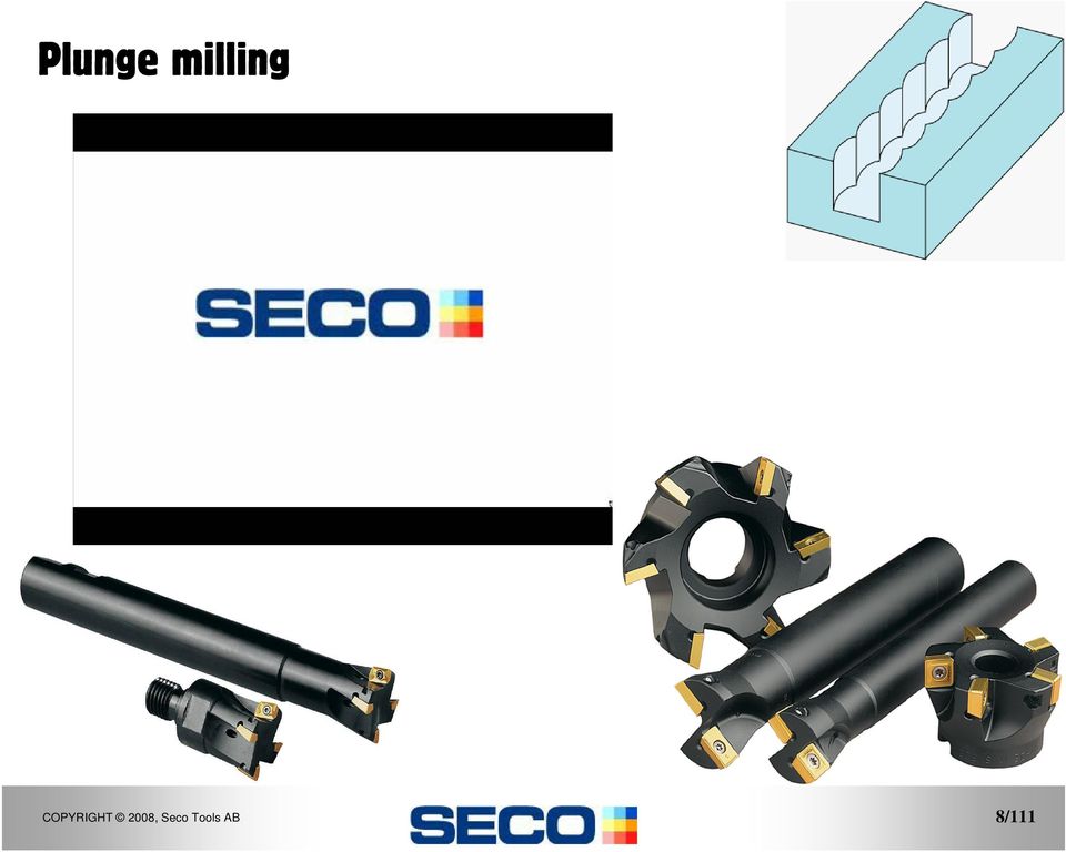
8 Plunge milling 8/111
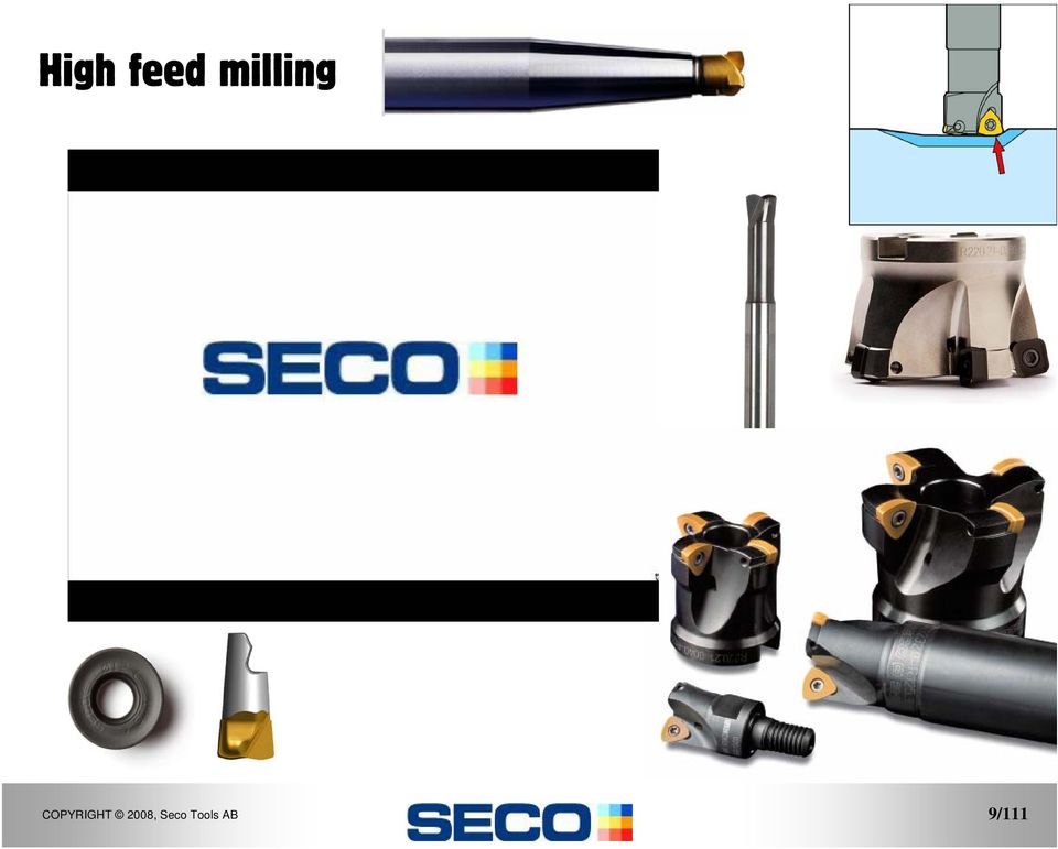
9 High feed milling 9/111
10 Thread milling 10/111

11 Solid Carbide milling 11/111

12 Mini milling cutters A full range cutters from 0,004 up to diameter. 62HRc Phone Mold 12/111

13 Mill Turning Face Turnmilling Cutter off centre-line Peripheral Turnmilling (helical interpolation ramping) External Cutter on centre-line Internal 13/111

14 Cutting depth a p inch Machine Capability Insert application insert dimensions cutting conditions Power Turbo Super Turbo Micro Turbo Nano Turbo Feed f z inch/tooth (Typical example) 14/111

15 Nomenclature & Cutter Geometry 15/111

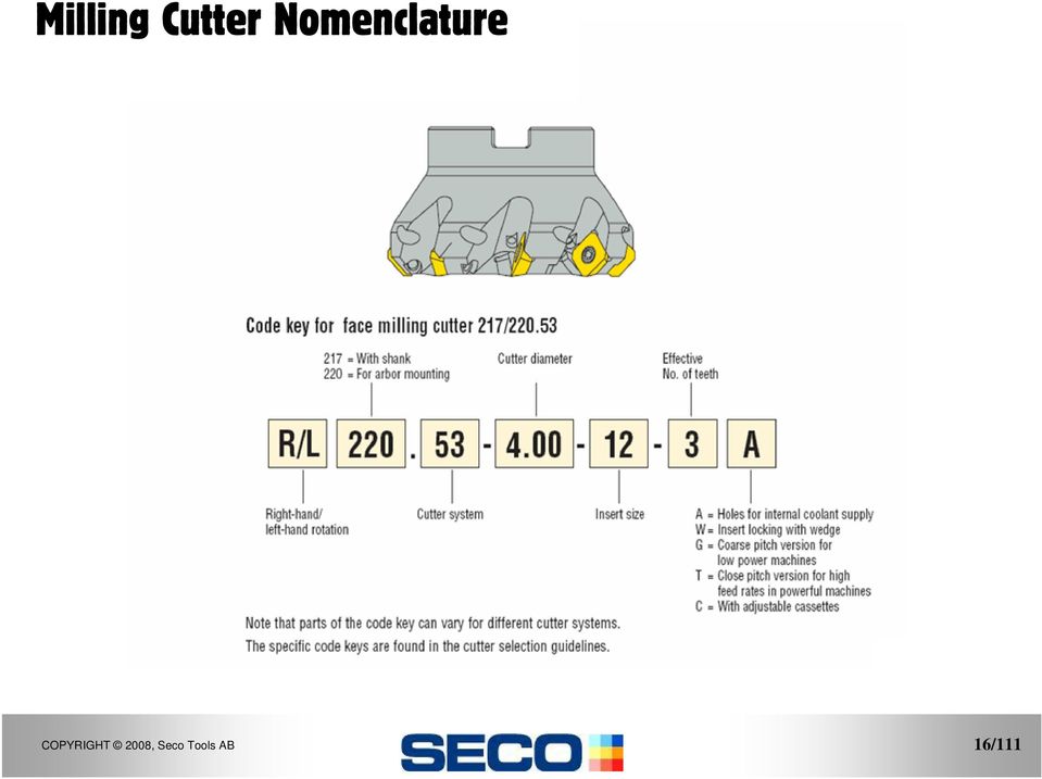
16 Milling Cutter Nomenclature 16/111
17 Cutter Geometry Milling cutter geometry Cutting forces Power Metal removal rate Cutting edge geometry Tool life Cutting forces Chip breaking geometry Chip formation Cutting forces 17/111

18 Cutter positioning Cutter Geometry Entry shock (pressure stress) Exit shock (tensile stress) 18/111

19 The difference between milling and turning Varying cutting forces (stress). Varying cutting temperatures (tension in insert). Milling has varying chip thickness. Turning has a constant chip thickness. 19/111

20 Varying Edge Temperature Chipping Thermal cracks 20/111

21 Cutter Geometry γ p κ γ f Milling cutter geometry = Positioning of the cutting edge Lead angle - κ Axial rake angle - γ p Radial rake angle - γ f 21/111
22 Cutter Geometry Positive positive Advantages/disadvantages + Smooth cutting. + Good chip removal. + Good surface smoothness. - Cutting edge strength. - Unfavorable entry contact. - Draws workpiece away from machine table. 22/111
23 Cutter Geometry Negative negative Advantages/disadvantages + Cutting edge strength. + Productivity. + Pushes the workpiece towards the machine table. - Large cutting forces. - Chip obstruction. 23/111
24 Cutter Geometry Negative vs. Positive Double negative Double positive 24/111
25 Cutter Geometry Positive negative Advantages/disadvantages + Good chip removal. + Favorable cutting forces. + Wide range of applications. 25/111
26 Insert nomenclature & cutting edge geometry. 26/111
27 Milling Insert Nomenclature OFER070405TN-ME15 T25M 27/111
28 Edge Condition and Rake Angle OFER070405TN-ME15 T25M -E -ME -M -MD 28/111
29 Ultra High Positive Rake /111
30 Milling Cutter Application. 30/111
31 Conventional Climb Conventional milling Used on older machines / unstable conditions. Unfavorable milling process. Climb milling Favorable milling process. Not recommended on older machines / unstable conditions. 31/111
32 Cutter positioning The basic problem in conventional milling is the insert entry. Cutting edge radius, rubbing the edges away not enough heat! Self-hardening materials Stainless Steel. Chip jamming/obstruction. 32/111
33 Cutter positioning Climb milling can be used for most processes. The machine must have a stable setup and spindle with no play. (Modern CNC machines) Advantages of climb milling Longer tool life. The chips land behind the cutter on the surface just milled, and will therefore not be machined again. Climb milling causes a downward pressure and therefore does not lift up the workpiece. Better surface finish. Easier chip removal. Requires less power. 33/111
34 Cutter positioning Conventional milling Central milling Combination of climb and conventional milling. Unfavorable due to varying cutting forces. Unavoidable when slot milling Climb milling 34/111
35 pitch Arc of tool engagement. Insert spacing. Arc of tool engagement. 35/111
36 Cutter Engagement Under-formed chip Undesirable, sometimes unavoidable. Thick chip Desirable, better tool life. 36/111
37 Cutter positioning Entry shock (pressure stress) Exit shock (tensile stress) If possible position the cutter as shown on the right, if you can. 37/111
38 Cutter positioning Interrupted cut milling Short tool life (cutting edge breakage). Vibration problems. This is often unavoidable! 38/111
39 Milling cutter pitch pitch : Impact of each tooth. : Vibration amplitude. Normal pitch Differential pitch Differential pitch reduces the risk of vibration. 39/111
40 Vibrations F F z F x The size and direction of the cutting force for a face milling cutter, 45 entering angle (sum of axial and radial forces perpendicular to cutting edge). 40/111
41 Vibrations F F z F x The size and direction of the cutting force for a square shoulder milling cutter, 90 entering angle. (sum of axial and radial forces perpendicular to cutting edge). 41/111
42 Vibrations n = fz = hm D ae (1 sink) fz = hm D ae Change cutter positioning Minimise tool overhang Improve stability (n π D) 12 f = ( z or k) fz v c 12 π D vf = n ( z or k) fz Decrease cutting speed Increase feed Decrease depth of cut Conventional milling Q = ae ap vf 42/111
43 Vibrations 43/111
44 Average chip thickness 44/111
45 Average chip thickness f z Chip thickness = Thickness of the undeformed chip at right angles to cutting edge.. and is constantly changing. 45/111
46 Average chip thickness f z 46/111
47 Average chip thickness f z h m Chip thickness = Thickness of the undeformed chip at right angles to cutting edge.. and is constantly changing THEREFORE average chip thickness is important. 47/111
48 Average chip thickness Calculating the average chip thickness, to achieve the correct cutting data should only be applied when Ae is LESS THAN 50% f z Dc h m Ae = 50% 48/111
49 Average chip thickness Relationship between feed and average chip thickness. Radial cutting depth - Diameter of the cutter. Cutter positioning. Entering angle. 49/111
50 Average chip thickness f z f z a e Dc Dc h m a e h m Radial cutting depth Diameter of the cutter (a e /D c ratio) What is happening to the average chip thickness as Ae reduces? 50/111
51 Average chip thickness f z Which will have the higher feed rate? 51/111
52 Average chip thickness Formula to calculate f z for square shoulder milling: f z = h m D a e 2.5 = = = legend f z = feed per tooth h m = average chip thickness D = cutter diameter a e = radial width of cut example find the f z of a Turbo mill: h m = D = 2.5 a e = /111
53 Average chip thickness v f = 21.5 v f = 25.8 v f = 48.5 v f = 64.5 v f = % engagement 50% engagement 20% engagement 10% engagement 5% engagement 53/111
54 Description a e Width of cut a p Depth of cut ( v c ) SFPM (f z ) FPT (h m ) Average Chip (n) RPM (v f ) Feed Rate IPM Slotting 100% Engagement Profiling 50% Engagement Profiling 20% Engagement Profiling 10% Engagement Profiling 5% Engagement /111
55 Average chip thickness a e Caution! 55/111
56 Average chip thickness Caution! 56/111
57 Average chip thickness a e Caution! 57/111
58 Average chip thickness 90deg 45deg h : 100% h : 70% f z : 100% f z : 100% 58/111
59 Average chip thickness h = f z x sin (ҳ ) 59/111
60 Average chip thickness Formula to calculate f z for face milling: D f = h z m a e 1 sinκ x x 1.41 = legend f z = feed per tooth h m = average chip thickness D = cutter diameter a e = radial width of cut κ = setting angle example find the f z of a Octomill face mill: h m = D = 4 a e = 0.8 κ = 43 o 60/111
61 Average chip thickness Relationship between feed and average chip thickness. Radial cutting depth - Diameter of the cutter. Small a e /D c gives larger feeds. Cutter positioning. Single sided cutting gives larger feeds. Entering angle. Smaller angle of engagement gives larger feeds. 61/111
62 Average chip thickness Feed and average chip thickness Average chip thickness. If too large broken inserts. If too small extra wear. 62/111
63 Average chip thickness For 90 lead angle cutters only 63/111
64 Average chip thickness 64/111
65 Cutting edge geometry 65/111
66 . Cutting edge geometry Difficult machining strong edges D MD SE.. AFTN -MD15 SE.. AFTN -D16 M SE.. AFTN -M14 SE.. AFTN -M15 SE.. AFTN -M16 Easy machining sharp edges ME E SE.. AFN -E07 SE.. AFTN -ME10 SE.. AFN -E12 SE.. AFTN -ME13 SE.. AFTN -ME decreasing chip thickness increasing 66/111
67 Cutting edge geometry The vertical axis specifies the degree of difficulty in the machining operation (i.e. E = Easy, M = Medium etc.) The horizontal axis denotes the application range. The numbers indicate the average chip thickness in mm, 10 meaning 0.1mm or meaning 0.13mm or etc. XOMX TR-ME13 F40M 67/111
68 Cutting edge geometry -ME06 example ME06 geometry is for medium easy machining operations h m should be kept at 0.06mm (0.002 ) under normal conditions and for average material (Seco material group 3-5) 68/111
69 Cutting edge geometry -M10 example M10 geometry is for medium machining operations h m should be kept at 0.10mm (0.004 )under normal conditions and for average material (Seco material group 3-5) 69/111
70 Cutting edge geometry To maintain maximum tool life, it is crucial to exceed or at least equal the edge protection chamfer. Cutting speed can also be increased in side milling operations thereby optimizing the application. 70/111
71 Milling methods 1. Peeling Method 2. High speed machining 3. High feed machining 4. Plunge milling 71/111
72 Peeling method Small radial cutting depth Deep cutting depth High cutting speed Spiral Cutter Roughing method which normally eliminates semi-finishing 72/111
73 Peeling method Ae=.060 Ap= MM B90A30-E05 Rpm=6630 Vf= 70 inch/min 73/111
74 High speed machining Small cutting depth Small radial cutting depth Small average chip thickness High cutting speed Sharp cutting edges in hard grades 74/111
75 High feed milling Small cutting depth Very high feed per tooth High cutting speed Good method in hardened steel and difficult material Roughing method which normally reduces the cutting depth for semi-finishing 75/111
76 High feed milling Minimaster high feed insert R high feed cutter Jabro high feed cutter 76/111
77 Plunge Milling Method mostly for long overhang or weak machines Normal cutting speed Good method for difficult material like Inconel Roughing method which normally increase productivity 77/111
78 Plunge Milling Tool 1 Tool= R V= 524 sft/min Fz= per/tooth Side step = 3/8 Tool 2 Tool= L V=524 sft/min Fz= per/tooth Side step= ½ Tool 3 Tool= R V= 524 sft/min Fz= per/tooth Side step= ¼ then /111
79 Trochoidal Milling The Trochoidal method is a fast and productive method for slotting operations. D c Step over Width 79/111
80 Surface Finish Small radius corner insert Large radius corner insert Faceted corner insert Faceted insert plus Wiper insert 80/111
81 Surface Finish Axial run-out with a non adjusted cutter. Cassettes give a better surface finish when correctly adjusted. 81/111
82 Surface finish & tool life. Tool life Tool tolerances Measured with a reference insert Modern Classic Run - out influences The tool life. The surface finish. Machining noise level. Axial/radial run-out (Typical example ) 82/111
83 Milling insert clamping Common method uses a screw though the insert. The insert is clamped in the centre, screw head below insert! This system is commonly used for modern milling cutters. This system allows the use of modern chip face geometries. 83/111
84 Maintenance Always clean the insert seating before clamping a new insert in place. Always replace damaged anvils or the tool if the insert seating is damaged. Never use re-built (welded) tools. Replace damaged screws and keys. Lubricate moving parts regularly. Always use the correct keys (dynamometric keys). Always position the insert carefully before clamping it in place. Make sure the insert fits flush against the supports. If the insert is not positioned correctly, it will not be clamped properly (insert breakage). 84/111
85 Milling 85/111
Chapter 6 Machining Center Carbide Insert Fundamentals
 This sample chapter is for review purposes only. Copyright The Goodheart-Willcox Co., Inc. All rights reserved. N10G20G99G40 N20G96S800M3 N30G50S4000 N40T0100M8 N50G00X3.35Z1.25T0101 N60G01X3.25F.002 N70G04X0.5
PROVEN SOLUTIONS FLIUD END MACHINING FLUID END MACHINING PROVEN SOLUTIONS & TOOLING
 PROVEN SOLUTIONS FLIUD END MACHINING FLUID END MACHINING PROVEN SOLUTIONS & TOOLING SECO PROVEN SOLUTIONS WILL IMPROVE YOUR PROCESS When you partner with Seco, our team of metalworking experts evaluate
High speed machining and conventional die and mould machining
 High speed machining and conventional die and mould machining Reprint from HSM - High Speed Machining There are a lot of questions about HSM today and many different, more or less complicated, definitions
Turning Formulas. RPM = n (rev/min) Revolutions per minute. A measure of spindle speed
 Revolutions per minute. A measure of spindle speed") Turning Formulas 1/14 RPM = n (rev/min) Revolutions per. A measure of spindle speed n = 3.82 (v c D) n = Rpm (rev/min) v c = Cutting Sped (SFPM) D = Workpiece Diameter v c = 750 D = 2.0 n = 3.82 x (750
Turning Formulas 1/14 RPM = n (rev/min) Revolutions per. A measure of spindle speed n = 3.82 (v c D) n = Rpm (rev/min) v c = Cutting Sped (SFPM) D = Workpiece Diameter v c = 750 D = 2.0 n = 3.82 x (750
CNC Applications. Tool Radius Compensation for Machining Centers
 CNC Applications Tool Radius Compensation for Machining Centers Why Cutter Diameter Compensation? When machining finished surfaces with the side of a milling cutter (generally called profiling), the accuracy
Milling. Contents. Milling
 ontents Milling The Milling process... 5 asic milling definitions... 6 pplication of milling cutters... 9 Milling direction... 9 utter diameter position... 10 ntry and exit considerations... 11 ntering
THE INFLUENCE OF STEEL GRADE AND STEEL HARDNESS ON TOOL LIFE WHEN MILLING IN HARDENED TOOL STEEL
 THE INFLUENCE OF STEEL GRADE AND STEEL HARDNESS ON TOOL LIFE WHEN MILLING IN HARDENED TOOL STEEL S. Gunnarsson, B. Högman and L. G. Nordh Uddeholm Tooling AB Research and Development 683 85 Hagfors Sweden
GEOMETRY OF SINGLE POINT TURNING TOOLS
 GEOMETRY OF SINGLE POINT TURNING TOOLS LEARNING OBJECTIVES Introduction to Features of single point cutting tool. Concept of rake and clearance angle and its importance System of description of Tool geometry
Three Key Elements of a Cutting Tool
 End Mill Training Three Key Elements of a Cutting Tool Geometry Cutting Tool 3 Elements Needed in a Good Cutting Tool Well Balanced For Best Performance Only Good as the Weakest Link End Mill Terms A -
CNC Applications Speed and Feed Calculations
 CNC Applications Speed and Feed Calculations Photo courtesy ISCAR Metals. Turning Center Cutters What types of cutters are used on CNC turning Centers? Carbide (and other hard materials) insert turning
Milling and Machining Center Basics
 Training Objectives After watching the video and reviewing this printed material, the viewer will gain knowledge and understanding of basic milling theories and procedures. In addition, the viewer will
Radius Compensation G40, G41, & G42 (cutter radius compensation for machining centers, tool nose radius compensation for turning centers)
") Radius Compensation G40, G41, & G42 (cutter radius compensation for machining centers, tool nose radius compensation for turning centers) These features are commonly well covered in most basic CNC courses.
Radius Compensation G40, G41, & G42 (cutter radius compensation for machining centers, tool nose radius compensation for turning centers) These features are commonly well covered in most basic CNC courses.
Milling & Machining Centers
 Training Objective After watching the program and reviewing this printed material, the viewer will gain knowledge and understanding of basic milling theories and procedures. In addition, the viewer will
8.1 HPC for improved efficiency on standard machine tools by using new fluid-driven spindles
 8.1 HPC for improved efficiency on standard machine tools by using new fluid-driven spindles A. Schubert 1, O. Harpaz 2, B. Books 2, U. Eckert 1, R. Wertheim 1 1 Fraunhofer IWU, Reichenhainer Str. 88,
1001 Business Center Drive Mount Prospect, IL 60056-2181 Toll Free: (800) 950-5202 Phone: (847) 635-0044 Fax: (847) 635-7866
 950-5202 Phone: (847) 635-0044 Fax: (847) 635-7866") 1001 Business Center Drive Mount Prospect, IL 60056-2181 oll Free: (800) 950-5202 Phone: (847) 635-0044 Fax: (847) 635-7866 http://www.sumicarbide.com Sumitomo offers advanced milling, drilling, and hard
1001 Business Center Drive Mount Prospect, IL 60056-2181 oll Free: (800) 950-5202 Phone: (847) 635-0044 Fax: (847) 635-7866 http://www.sumicarbide.com Sumitomo offers advanced milling, drilling, and hard
U-Max Chamfering endmill SPMT-WL 0.17 (0.08-0.21) -WH 0.35 (0.10-0.42) R215.64. Long edge cutter 215.3 0.17 (0.10-0.20) R215.3 -AAH 0.12 (0.08-0.
 -WH 0.35 (0.10-0.42) R215.64. Long edge cutter 215.3 0.17 (0.10-0.20) R215.3 -AAH 0.12 (0.08-0.") General Turning PROFILING Feed recommendations Feed per tooth, fz (mm/tooth) Insert geometry Insert size Starting value (min.- max.) U-Max Chamfering endmill SPMT-WL 0.17 (0.08-0.21) -WH 0.35 (0.10-0.42)
General Turning PROFILING Feed recommendations Feed per tooth, fz (mm/tooth) Insert geometry Insert size Starting value (min.- max.) U-Max Chamfering endmill SPMT-WL 0.17 (0.08-0.21) -WH 0.35 (0.10-0.42)
Up to Speed. When considering a modern CNC. Spindle speeders allow micromachining on lower-rpm machines
 Up to Speed Spindle speeders allow micromachining on lower-rpm machines By Gerard Vacio, BIG Kaiser Precision Tooling Inc. As cutting tool manufacturers increase the recommended operating conditions for
MACHINING OPERATIONS AND MACHINE TOOLS
 MACHINING OPERATIONS AND MACHINE TOOLS 1. Turning and Related Operations 2. Drilling and Related Operations 3. Milling 4. Machining & Turning Centers 5. Other Machining Operations 6. Shape, Tolerance and
Think precision, Think HSS REAMING
 Think precision, Think HSS REAMING SUMMARY REAMING TOOLS 2 Zoom on a reamer 3 Which HSS for maximum efficiency? 4 Coatings for the best performance 5 Vocabulary 6 Choose the right design 7 Types of bevel
Heavy Roughning Milling Cutter. MSR Series. Improving machine efficinecy. Double the productivity. Square Insert MSR Facemill. Insert lineup expanded
 Heavy Roughning Milling Cutter MSR Series Improving machine efficinecy Square Insert MSR Facemill MonSteR M S R Square S Mill Double the productivity MonSteR M S R Mill Insert lineup expanded Heavy Milling
Boring. Contents. Boring
 ontents oring oring ackground... 3 oring operation types... 4 oring tools... 5 hoice of boring tool type... 6 Roughing... 6 inishing... 7 Inserts for boring... 8 uilding and setting boring tools... 9 Ways
Tooling concepts Gear milling
 Tooling concepts Gear milling Complete gear-cutting solutions optimized for your needs About ninety percent of all gear wheel manufacturing involves metal cutting. Your main opportunities for rationalizing
Technical Information
 tapping Technical Information Troubleshooting Guide 115 TAP DOES NOT START Program depth: Tap drill size: Tap sharpness: Compression stroke may use up the entire program depth. Check for tap drill size.
Overview. Milling Machine Fundamentals. Safety. Shop Etiquette. Vehicle Projects Machine Shop
 Overview Milling Machine Fundamentals Wayne Staats, UW-Madison FSAE Safety Shop Etiquette Before Machining Indicating Calculating Feeds and Speeds Machining Maintenance Safety Respect the machines Common
InvoMilling AGILE GEAR MANUFACTURING
 InvoMilling AGILE GEAR MANUFACTURING Cutting lead times in gear manufacturing Machining gears normally requires dedicated tools for the specific gear profile. With the patented InvoMilling process it is
GEAROLOGY 4-1 WORMS AND WORM GEARS WORMS AND WORM GEARS
 GEAROLOGY 4-1 4 4-2 GEAROLOGY COMMON APPLICATIONS: Worm and worm gear sets are used in many, everyday products including: electrical mixers, hubometers, right Now that you have an understanding of two
PRELIMINARY BROCHURE. Uddeholm Corrax
 PRELIMINARY BROCHURE Uddeholm Corrax Uddeholm Corrax Uddeholm Corrax stainless moulds steel has a unique set of properties that makes it the ultimate choice in a large number of demanding applications.
A Fuzzy System Approach of Feed Rate Determination for CNC Milling
 A Fuzzy System Approach of Determination for CNC Milling Zhibin Miao Department of Mechanical and Electrical Engineering Heilongjiang Institute of Technology Harbin, China e-mail:miaozhibin99@yahoo.com.cn
Inno vation. Parting and grooving program HX Heavy duty machining - stability & process security
 Inno vation Parting and grooving program HX Heavy duty machining - stability & process security EN Application - customer benefi ts Industries Power generation, turbine construction oll production Wind
Computer-Aided Numerical Control (CNC) Programming and Operation; Lathe Introduction, Advanced Mills
 Programming and Operation; Lathe Introduction, Advanced Mills") 1 of 6 9/9/2014 3:59 PM I. Catalog Information Credit- Degree applicable Effective Quarter: Fall 2014 MCNC 75B Computer-Aided Numerical Control (CNC) Programming and Operation; Lathe Introduction, Advanced
1 of 6 9/9/2014 3:59 PM I. Catalog Information Credit- Degree applicable Effective Quarter: Fall 2014 MCNC 75B Computer-Aided Numerical Control (CNC) Programming and Operation; Lathe Introduction, Advanced
Introduction to JIGS AND FIXTURES
 Introduction to JIGS AND FIXTURES Introduction The successful running of any mass production depends upon the interchangeability to facilitate easy assembly and reduction of unit cost. Mass production
Gear Cutting Tools. Hobbing Gear Milling. Leitz Metalworking Technology Group
 Gear Cutting Tools Hobbing Gear Milling Leitz Metalworking Technology Group Important information Important information 4 Services 5 An introduction to FETTE 6 Page Important information Product range
Advantages and application of PCD and CBn tools
 PCD and CBN tools Advantages and application of PCD and CBn tools Powerful and economical Tools with PCD and CBN cutting edges are the ideal solution for difficult-to machine, highly abrasive materials.
Table of contents BRAZED TURNING TOOLS. Toolholders H 2. Tips H 6. Rods H 8. Technical information H 9 H 1
 Table of contents BRAZED TURNING TOOLS Toolholders 2 Tips 6 Rods 8 9 1 ISO External holders General turning External Ordering Tip According to ISO243-1975 (DIN 4982-198) h b l 1 f 1 f 2 a p r ε γ 1) λ
Making 3D Threads in Feature Based Solid Modelers
 Making 3D Threads in Feature Based Solid Modelers THREAD BASICS Making true geometric threads in feature-based solid modelers is a fairly straightforward process and can be handled using several different
BRUSHHOLDERS AND THE PERFORMANCE OF CARBON BRUSHES
 Tech Note No. 22 TECH NOTE NO. 22 Brushholders and the Performance of Carbon Brushes Reliable Solutions Today! EA SA ELECTRICAL SERVICE APPARATUS ASSOCIATION BRUSHHOLDERS AND THE PERFORMANCE OF CARBON
Cutting Tool Materials
 Training Objectives After watching the video and reviewing this printed material, the viewer will gain knowledge and understanding of cutting tool metallurgy and specific tool applications for various
RAMAX S Prehardened stainless holder steel
 T O O L S T E E L F A C T S RAMAX S Prehardened stainless holder steel Wherever tools are made Wherever tools are used This information is based on our present state of knowledge and is intended to provide
Cutting Processes. Simulation Techniques in Manufacturing Technology Lecture 7
 Cutting Processes Simulation Techniques in Manufacturing Technology Lecture 7 Laboratory for Machine Tools and Production Engineering Chair of Manufacturing Technology Prof. Dr.-Ing. Dr.-Ing. E.h. Dr.
FRAUNHOFER INSTITUTE FOR MACHINE TOOLS AND FORMING TECHNOLOGY IWU HYBRID MACHINING PROCESSES IN CUTTING TECHNOLOGY
 FRAUNHOFER INSTITUTE FOR MACHINE TOOLS AND FORMING TECHNOLOGY IWU HYBRID MACHINING PROCESSES IN CUTTING TECHNOLOGY VIBRATION-SUPERIMPOSED MACHINING Hybrid Machining Processes Principle Process Variants
Understanding the Wire EDM Process
 5 Understanding the Wire EDM Process 69 Accuracy and Tolerances Wire EDM is extremely accurate. Many machines move in increments of 40 millionths of an inch (.00004") (.001 mm), some in 10 millionths of
Making Wooden Hinges
 Making Wooden Hinges By Alex Reid - www.mokkou.jp Materials and tools used - 3.2mm straight router bit - 1/8 round-over router bit - Flush-cut straight bit (with bearing on bottom) - Finger-joint jig -
SprutCAM is a CAM system for NC program generation for machining using multi-axis milling, turning, turn/mill, Wire EDM numerically controlled
 SprutCAM is a CAM system for NC program generation for machining using multi-axis milling, turning, turn/mill, Wire EDM numerically controlled machines and machining centers. The system enables the creation
Solid shape molding is not desired in injection molding due to following reasons.
 PLASTICS PART DESIGN and MOULDABILITY Injection molding is popular manufacturing method because of its high-speed production capability. Performance of plastics part is limited by its properties which
Mechanics and Dynamics of 5-axis Ball-end Milling Operations
 Mechanics and Dynamics of 5-axis Ball-end Milling Operations Erdem OZTURK, PhD.Candidate L.Taner TUNC, PhD. Candidate Assoc.Prof. Erhan BUDAK Manufacturing Research Laboratory, SABANCI UNIVERSITY, ISTANBUL
Manufacturing Tooling Cutting Tool Design. Elements of Machining. Chip Formation. Nageswara Rao Posinasetti
 Manufacturing Tooling Cutting Tool Design Nageswara Rao Posinasetti Elements of Machining Cutting tool Tool holding Guiding device Work piece Machine tool January 29, 2008 Nageswara Rao Posinasetti 2 Chip
Whirling Machine. New Dimension of Whirling Technology. Thread Whirling Machines. Big Workpiece Diameter. High Pitch Thread
 LEISTRITZ PRODUKTIONSTECHNIK GMBH Thread Whirling Machines Whirling Machine New Dimension of Whirling Technology Big Workpiece Diameter High Pitch Thread Customer Satisfaction remains the Highest Priority
InventorCAM + Inventor. The complete integrated Manufacturing Solution GETTING STARTED
 InventorCAM + Inventor The complete integrated Manufacturing Solution GETTING STARTED InventorCAM imachining InventorCAM imachining is an intelligent High Speed Machining CAM software, designed to produce
Milling Milling milling cutter milling machines 1
 Milling Milling is a basic machining process by which a surface is generated progressively by the removal of chips from a workpiece as it is fed to a rotating cutter in a direction perpendicular to the
UNITED STATES CUTTING TOOL INSTITUTE Product Groupings for Standards Activities CUTTING TOOL PRODUCTS
 CUTTING TOOL PRODUCTS 1. BORING ISO 5609 Boring bars for indexable inserts Dimensions ISO 6261 Boring bars (tool holders with cylindrical shank) for indexable inserts Designation JIS B 4128 Boring bars
HOBBING MACHINE TYPE ZFWZ 8000x40
 Inventory number 416/635 Year of production 1973 Serial number 7160 HOBBING MACHINE TYPE ZFWZ 8000x40 Application The machine is provided for milling cylindrical, helical and helix cogwheels. The tooth
General Guidelines for Building Aluminum Production Injection Molds
 General Guidelines for Building Aluminum Production Injection Molds Using 7000 series Aluminum Mold Plate By David Bank Aluminum Injection Mold Company Rochester, New York 1 Introduction This high strength
Drill String Design. The following topics will be discussed
 Drill String Design The following topics will be discussed Kelly Drill pipe Drill collars Accessories; heavy wall drill pipe, jars, stabilizers, reamers, shock sub and bit sub Drill bits 1 Kelly Used to
COATED CARBIDE. TiN. Al 2 O 3
 COATED CARBIDE GENERAL INFORMATION CVD = Chemical Vapour Deposition coated grades GC2015, GC2025, GC2135, GC235, GC3005, GC3015, GC3020, GC3025, GC3115, GC4015, GC4025, GC4035, S05F, and CD1810. PVD =
METALWORKING PRODUCTS. Deep hole drilling Product catalogue and application guide
 METALWORKING PRODUCTS Deep hole drilling Product catalogue and application guide AB Sandvik Coromant Not only a tool supplier Sandvik Coromant is the No.1 supplier of cutting tools for the metalworking
PLQE. The base of the economy gearboxes with square output flange. Economy Line. Formerly PLE
 20 ormerly PL The base of the economy gearboxes with square output flange The PL series with square output flange. A powerful alternative for additional higher radial and axial loads. Low backlash High
is decisive if contour turning is involved.
 Toolholder selection The clamping system of the insert in the toolholder should be selected first. Toolholders have been ed to provide optimum performance in different applications and usually over a broad
COLLEGE OF ENGINEERING AND APPLIED SCIENCE MACHINE SHOP TOOLS AND PRACTICES
 COLLEGE OF ENGINEERING AND APPLIED SCIENCE MACHINE SHOP TOOLS AND PRACTICES I. OBJECTIVE To provide an overview and basic knowledge of the University of Wyoming, College of Engineering, equipment, tools,
DESIGN OF ADAPTIVE MULTI TOOL ARBOR ATTACHMENT
 INTERNATIONAL JOURNAL OF MECHANICAL ENGINEERING AND TECHNOLOGY (IJMET) International Journal of Mechanical Engineering and Technology (IJMET), ISSN 0976 6340(Print), ISSN 0976 6340 (Print) ISSN 0976 6359
indexable Center Drill
 Our innovative tooling design upgrades productivity and competitive capability while reducing production requirements in a range of industries. The tooling system is designed to benefit users of machining
CUTTING TOOL TECHNOLOGY. 1. Tool life 2. Tool Materials 3. Tool Geometry 4. Cutting fluids
 CUTTING TOOL TECHNOLOGY 1. Tool life 2. Tool Materials 3. Tool Geometry 4. Cutting fluids 1 Introduction Machining is accomplished by cutting tools. Cutting tools undergo high force and temperature and
Solid End Mill Series
 Solid End Mill Series Carbide material Now available! For automatic lathe New! 57 types, 52 descriptions Easy to use total length of 35mm and 45mm are available Solid End Mill Series Kyocera's solid end
Milling Chuck Features
 Milling Chuck Features Since its first introduction into the industry in 1963, Nikken has sold over 2,000,000 worldwide and never stopped improving its original design. Featuring multi-roller bearings
How To Design A 3D Print In Metal
 DMLS / SLM Metal 3D Printing. An introductory design guide for our 3d printing in metal service. v2.2-8th July 2015 Pricing considerations. Part Volume. One of the biggest factors in the price for DMLS
CORE COMPETENCY REQUIREMENTS NIMS CERTIFIED CNC SET UP PROGRAMMER MILLING AND TURNING
 CORE COMPETENCY REQUIREMENTS NIMS CERTIFIED CNC SET UP PROGRAMMER MILLING AND TURNING APPRENTICE CORE COMPETENCIES 1. Identify and Demonstrate Usage of Machine Safety and Personal Protective Equipment
MATERIALIZING VISIONS. Bohler-Uddeholm P20 Modified
 MATERIALIZING VISIONS Bohler-Uddeholm P20 Modified General Bohler-Uddeholm P20 Modified is a Cr-Mo-alloyed steel which is supplied in the hardened and tempered condition. P20 Modified offers the following
OD 1401 9 PRECISION MEASURING INSTRUMENTS
 SUBCOURSE EDITION OD 1401 9 PRECISION MEASURING INSTRUMENTS PRECISION MEASURING INSTRUMENTS SUBCOURSE OD1401 EDITION 9 Unites States Army Combined Arms Support Command Fort Lee, VA 23801-1809 5 CREDIT
IHSS-N1 WELDED HONEYCOMB CORE SPECIFICATION. Generated: Sergiy Papyshev Engineering. Approved: Don Prysi Manufacturing. Approved: Merzuk Ramic Quality
 IHSS-N1 WELDED HONEYCOMB CORE SPECIFICATION Generated: Sergiy Papyshev Engineering Approved: Don Prysi Manufacturing Approved: Merzuk Ramic Quality Approved: Steven Barnett Administrative DATE DATE DATE
Course outline. Know Your Machine From A Programmer s Viewpoint 11 If you ve had experience with conventional (non-cnc) machine tools 11
 machine tools 11") Course outline Know Your Machine From A Programmer s Viewpoint 11 If you ve had experience with conventional (non-cnc) machine tools 11 Machine Configurations 13 Vertical machining centers 13 C-frame style
Course outline Know Your Machine From A Programmer s Viewpoint 11 If you ve had experience with conventional (non-cnc) machine tools 11 Machine Configurations 13 Vertical machining centers 13 C-frame style
Chapter 3 Installing Over-the-Post Railing on an L-Shaped Stair
 49 Chapter 3 Installing Over-the-Post Railing on an L-Shaped Stair In this chapter: The Over-the-Post Balustrade System Determining the Rail Centerline Using Rail Bolts Making a Pitch Block Laying Out
Die casting Figure M2.3.1
 Die casting Die casting is a moulding process in which the molten metal is injected under high pressure and velocity into a split mould die. It is also called pressure die casting. The split mould used
Understanding Plastics Engineering Calculations
 Natti S. Rao Nick R. Schott Understanding Plastics Engineering Calculations Hands-on Examples and Case Studies Sample Pages from Chapters 4 and 6 ISBNs 978--56990-509-8-56990-509-6 HANSER Hanser Publishers,
Surface Machining. NATIONAL INSTITUTE FOR AVIATION RESEARCH Wichita State University. Revision 5.13 Copyright 2004. All rights reserved.
 Surface Machining NATIONAL INSTITUTE FOR AVIATION RESEARCH Wichita State University Revision 5.13 Copyright 2004. All rights reserved. www.cadcamlab.org None of this material may be reproduced, used or
How To Improve Your Turning
 Best practice machining of wind power components Tool and method advances for efficient manufacturing WIND POWER EDITORIAL Introduction Manufacturing parts for the wind-power industry is an opportunity
CHAIN CARE & TROUBLE SHOOTING
 Fatigue Failure Bushing Fatigue Stress Corrosion Stress Corrosion and Hydrogen Embrittlement These closely related failures are similar in appearance and nature. They appear as cracks which initiate at
Renishaw 2008. apply innovation TM. Calibrating 5-axis machines to improve part accuracy. 5Align
 Calibrating 5-axis machines to improve part accuracy 5Align Productive Process Pyramid TM Understanding and tracking machine behaviour Process verification Thermal compensation In-cycle process control
Lapping and Polishing Basics
 Lapping and Polishing Basics Applications Laboratory Report 54 Lapping and Polishing 1.0: Introduction Lapping and polishing is a process by which material is precisely removed from a workpiece (or specimen)
Two most common lock nut groups: 1-Prevailing Torque Type Lock Nuts:
 Two most common lock nut groups: 1. PREVAILING TORQUE a design feature of the lock nut produces friction between threads of mated components thereby increasing the force needed to tighten as well as loosen
Reproduced with the permission of the American Welding Society (AWS), Miami, Florida - 09/15/2011. 7. Stud Welding
, Miami, Florida - 09/15/2011. 7. Stud Welding") 7. Stud Welding 7.1 Scope Section 7 contains general requirements for welding steel studs to steel (see 7.2.7 and 1.2.2 for approved steels). In addition, it stipulates specific requirements for the following:
7. Stud Welding 7.1 Scope Section 7 contains general requirements for welding steel studs to steel (see 7.2.7 and 1.2.2 for approved steels). In addition, it stipulates specific requirements for the following:
Driven Toolholders for SAUTER Turrets
 Driven Toolholders for SAUTER Turrets Manufacturer of Precision Tools since 1974 INNOVATION PRECISION INDIVIDUALITY QUALITY SERVICE Table of Contents Type Page Driven Toolholders DIN 5482 - Disc-type Turrets
CNC Vertical Machining Center V-Mill CNC Large box-way and linear guide way machines
 CNC Vertical Machining Center Large box-way and linear guide way machines Technical Datasheet CNC Vertical Machining Center Large box-way and linear guide way machines Spindle gear drive (50-taper) for
Removing chips is a method for producing plastic threads of small diameters and high batches, which cause frequent failures of thread punches.
 Plastic Threads Technical University of Gabrovo Yordanka Atanasova Threads in plastic products can be produced in three ways: a) by direct moulding with thread punch or die; b) by placing a threaded metal
Parting and Grooving. External operations : 1. Parting off, 2. Grooving, 3. Turning, 4. Profiling, 5. Undercutting, 6. Face-grooving, 7.
 PRTIN N ROOVIN Parting and rooving utting off and making grooves In parting operations, the objective is to seperate, as efficiently and reliably as possible. one part of the workpiece from the other.
Screw Thread Design. Rev. 3-4-09
 Screw Thread Design Screw Thread Fundamentals A screw thread is defined as a ridge of uniform section in the form of a helix on either the external or internal surface of a cylinder. Internal threads refer
Product Guide SaraDrill
 Product Guide SaraDrill SARADRILL / A QUICK GUIDE Drilling from solid - a proven technology to drill large diameter holes on low horse power machines. Drilling from 49mm to 270mm diameter holes from solid
LEADER IN CUTTING TECHNOLOGY
 LEADER IN CUTTING TECHNOLOGY FOR OVER 2 YEARS REASONS WHY TRONEX IS THE BEST IN THE WORLD 1 2 SUPERIOR CUTTING PERFORMANCE Cut hundreds of thousands of times before dulling. Cut hundreds of thousands of
. Takım Tezgâhları: Planya, Freze ve İşlem Merkezleri
 1. Takım Tezgâhları: Planya, Freze ve İşlem Merkezleri.1 Examples of Parts Produced Using the Machining Processes in the Chapter Figure 23.1 Typical parts and shapes produced with the machining processes
Right Angle Grinder USA MADE FLAP DISCS
 USA MADE FLAP DISC Right Angle Grinder CGW Offers the Most Extensive Line of Flap Discs in the Marketplace CGW flap discs blend and finish in one operation which replaces the traditional twostep grinding
SEMAE3221 Machining aircraft components using CNC milling machines
 Machining aircraft components using CNC milling machines Overview This standard identifies the competences you need to operate Computer Numerical Control (CNC) three axis or five axis machines or CNC machining
Gear Engineering Data. Spur Gear Gear Formulas Drive Selection Horsepower and Torque Tables
 Engineering Gear Engineering Data Spur Gear Gear Formulas Drive Selection Horsepower and Torque Tables G-79 Gear Selection Stock Spur Gear Drive Selection When designing a stock gear drive using the horsepower
NEW INTERCHANGEABLE REAMING HEAD SYSTEM FAST
 August 2007 / NEW029.1 / PAGE 1 OF 7 NEW INTERCHANGEABLE REAMING HEA YTEM FAT ACCURATE GOO FINIH Ingersoll is introducing the QwikReam, a new high speed reaming system. The QwikReam consists of an interchangeable
Index. Illustrations CERAMIC PRODUCTIVITY MANUAL. Page. Page
 CERAMIC PRODUCTIVITY MANUAL Index Page What is a Whisker-Reinforced Ceramic...4 WG-300 Fracture Surface...4 Physical Properties...5 How to Use the Properties of Greenleaf Advanced Ceramics...6 Relative
ME 1355 CAD/CAM LABORATORY CNC MILLING PROGRAM. Study of G Codes and M Codes to Write Manual Part Programming for Fanuc Control Systems
 ME 1355 CAD/CAM LABORATORY CNC MILLING PROGRAM Ex.No.1 Study of G Codes and M Codes to Write Manual Part Programming for Fanuc Control Systems PREPARATORY FUNCTION ( G CODES ) The preparatory functions
This last dimension, the thread pitch diameter, is the most important as it is a reference from which all other thread measurements originate
 Training Objectives After watching the video and reviewing this printed material, the viewer will gain knowledge and understanding of the design and use of various thread types and how they are produced.
TechCut 4 Precision Low Speed Saw
 Product Brochure TechCut 4 Precision Low Speed Saw 3" - 6" Blade Range Digital Speed Display 1-Micron Sample Indexing Spring-Loaded Dressing Stick Attachment All Aluminum & Stainless Steel Construction
Technical Guide for Glass Cutting Section 1 - Two Basic Types of Cutting
 Section 1 - Two Basic Types of Cutting Part 1 Conventional Cutting Basic Principles of Glass Cutting This portion of Part 1 deals with those aspects of the basic principles of glass cutting that are common
Q&A Session for Advanced Ball Screws 102: Troubleshooting for Design Engineers
 Q&A Session for Advanced Ball Screws 102: Troubleshooting for Design Engineers Topic: Noise Q: Is there a way to predict/calculate noise on a ball screw? A: No, there is no way to calculate the noise of
CNC Applications. Introduction to Machining Centers
 CNC Applications Introduction to Machining Centers Machining Centers A machining center is simply a CNC milling machine with an automatic tool changer and an enclosure. There are a number of different
Florida Building Code 2004 SECTION 1009 STAIRWAYS AND HANDRAILS
 Florida Building Code 2004 SECTION 1009 STAIRWAYS AND HANDRAILS 1009.1 Stairway width. The width of stairways shall be determined as specified in Section 1005.1, but such width shall not be less than 44