Structure Design. Preface What's New? Getting Started Basic Tasks Advanced Tasks Workbench Description Customizing Glossary Index
|
|
|
- Jonas Paul
- 9 years ago
- Views:
Transcription
1 Structure Design Preface What's New? Getting Started Basic Tasks Advanced Tasks Workbench Description Customizing Glossary Index Dassault Systèmes All rights reserved.

2 Preface CATIA Version 5 Structure Design allows you to quickly model linear and curved structures, and plates using standard or user-defined sections. It addresses foundation and tooling design. As a scalable product, CATIA-Structure Design can be used with other CATIA Version 5 products such as CATIA-Part Design, CATIA-Assembly Design, CATIA-Sheetmetal Design, and CATIA-Generative Drafting. Using This Guide More Information

3 Using This Guide This book is intended to help you become quickly familiar with CATIA Structure Design. You should already be accustomed with basic CATIA Version 5 concepts such as document windows, standard and view toolbars. To get the most out of this guide, we suggest you start reading and performing the step-by-step Getting Started tutorial. Basic Task and Advanced Task sections present the main capabilities in the form of user tasks. It may be a good idea to take a look at the section describing the workbench menus and toolbars.

4 More Information Prior to reading this book, we recommend that you read the CATIA Version 5 Infrastructure User's Guide. The CATIA-Part Design User's Guide, CATIA-Assembly Design, CATIA-Sheetmetal Design and CATIA-Generative Drafting User's Guide may also prove useful. Click to find out more about Conventions used in this guide.

5 Conventions Certain conventions are used in CATIA, ENOVIA & DELMIA documentation to help you recognize and understand important concepts and specifications. The following text conventions may be used: The titles of CATIA documents appear in this manner throughout the text. File -> New identifies the commands to be used. The use of the mouse differs according to the type of action you need to perform. Use this mouse button, whenever you read Select (menus, commands, geometry in graphics area,...) Click (icons, dialog box buttons, tabs...) Double-click Shift-click Ctrl-click Check (check boxes) Drag Drag and drop (icons onto objects, objects onto objects) Drag Move Right-click (to select contextual menu) Graphic conventions are denoted as follows: indicates the estimated time to accomplish a task. indicates a target of a task. indicates the prerequisites. indicates the scenario of a task. indicates tips
 Click (icons, dialog box buttons, tabs.")
6 indicates a warning. indicates information. indicates the end of a task. indicates functionalities that are new or enhanced with this Release. Enhancements can also be identified by a blue-colored background in the left-hand margin.

7 What's New? Enhanced: When creating plates, you can now use the Sketcher to define the contour

8 Getting Started This tutorial will guide you step-by-step through your first Structure Design session, allowing you to get acquainted with the product. You will need a CATIA Version 5 session and should be familiar with basic concepts such as document windows, standard and view toolbars. You should be able to complete this tutorial in about 15 minutes. Setting Up Your Session Creating Columns Creating a Plate Bracing Your Structure Creating a Walkway Creating Infills Making Changes

9 Setting Up Your Session This first task shows you how to enter the Structure Design workbench and set up your V5 session. 1. Select File -> Open then select the GettingStarted.CATProduct document from the samples directory. 2. Select Mechanical Design ->Structure Design from the Start menu. The Structure Design workbench is displayed. 3. Switch to Design Mode (Edit -> Representations ). The document contains wireframe construction elements that will help you build the following foundation: 4. To ensure associativity between the structures you are going to create and the grid used as a construction aid, set the following options: Select Tools -> Options from the menu bar Click Mechanical Design -> Part Design in the left-hand box of the Options dialog box Click the General tab Check Keep link with selected object and Synchronize all external references. 5. Click Mechanical Design -> Structure Design in the left-hand box of the Options dialog box and select the Structure Design tab, then set member and plate material to Steel.

10 6. For access to available sections as well as to sample standard catalog sections, set the following options in the Structure Design tab: Enter the path of the directory containing sample standard catalog sections in the Directory field under Catalog storage: installation_folder/startup/components/structuralcatalogs For more information on the installation folder, see the CATIA Infrastructure User's Guide. Enter e:\tmp in the Directory field under Section storage to identify the path of the directory containing available sections 7. Click OK in the Options dialog box when done.

11 Creating Support Columns This task shows you how to create the four support columns of your structure. Columns use standard section IPE200 with a gravity anchor point. 1. Double-click the Member icon. The Member Definition and Point Definition dialog boxes appear. Double-clicking keeps the dialog box open letting you can create several columns. 2. Close the Point Definition dialog box. 3. Load the standard section, IPE200, that you will need: In the Section list, select Other section... The Catalogs dialog box listing the various catalogs available is displayed. Select the OTUA catalog. In the Family box, select the IPE type. In the Section box, select section IPE200. Click OK. The Section list in the Member Definition dialog box is updated. 4. Keep default options defining member type, anchor point and orientation.

12 5. In the Direction box list, select Parallel to the Z axis. 6. Select the start point of your column. 7. Select the end point of your column. The column is created in the geometry area and identified in the specification tree. In this case where a support (grid line) coincides with the start and end points used to create the column, you can also use the Member on Support command. 8. Repeat to create the other three columns. Your structure now looks like this:
 coincides with the start and end points used to create the column, you can")
13 Creating a Plate This task shows you how to create a plate on top of the support columns. 1. Click the Plate icon. The Plate Definition dialog box appears. 2. Enter the plate thickness, for example 100mm. 3. Select the grid plane as support plane. 4. Select the ends of linear members to define the contour of the plate: Note: The system shows you a preview to guide you when creating the plate. You need only select the ends of three members, the system closes the contour for you.

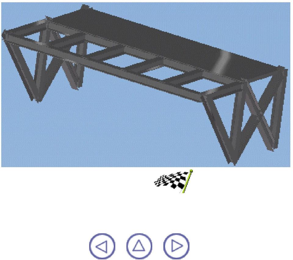
14 5. Select the arrow to invert the orientation of the thickness. 6. Click OK to create the plate. Your structure now looks like this:

15 Bracing Your Structure This task shows you how to brace both ends of your structure. 1. Double-click the Member icon. The Member Definition dialog box appears. Double-clicking keeps the dialog box open letting you can create several braces. 2. In the Type list, select V-Brace. 3. In the Section list, select IPE In the Anchor point list, select Gravity. 5. In the Direction box list, select Unspecified. 6. Select the top end of the first column. 7. Select the bottom end of the opposite column. The first part of the brace is created. 8. Select the bottom end of first column. 9. Select the top end of opposite column. The brace at this end of the structure is finished. 10. Repeat for the other end of the structure. Your structure now looks like this:

16 Creating a Walkway This task shows you how to create the linear members making up a walkway. The Linear Member Definition dialog box is still displayed. 1. In the Type list, select Beam. 2. In the Section list, select IPE In the Anchor point list, select Gravity top. 4. In the Direction list, select Parallel to the X-axis. 5. Click the Length checkbox and enter 2000 in the Length box. 6. Select column 1 and indicate to identify the positive direction: The first support beam is created. 7. Select column 4 and indicate to identify the positive direction: The second support beam is created. 8. In the Linear Member Definition dialog box, change the direction to Parallel to the xy plane. 9. Uncheck the Length checkbox. 10. Click the Offset checkbox and enter Select the two support beams you just created: The first connecting beam is created.

17 Be careful where you select the two beams. The system determines the end nearest the selection point to define the start and end points of the beam you want to create Select the two support beams again, this time at the other end: The second connecting beam is created. Note: This second beam is needed to create the infills and complete the walkway. You are now ready to brace your walkway. 13. In the Type list, select V-Brace. 14. Keep the same section, IPE In the Anchor point list, select Gravity. 16. In the Orientation box, use to arrows to change the angle to 90 degrees. 17. In the Direction list, select Parallel to XZ plane. 18. Uncheck the Offset checkbox. 19. Select the bottom end of column Select the far end of the first beam created. 21. Repeat for the other end of the walkway. 22. Click the Member icon to exit the command. Your structure now looks like this:

18

19 Creating Infills This task shows how to create infills to complete the walkway and your structure. 1. Click the Infill icon. The Infill Definition dialog box appears. 2. In the Type list, select Beam. 3. In the Section list, select IPE In the Anchor point list, select Top center. 5. Set the Orientation back to 0deg. 6. In the Number box, use the arrows to change the number of infills to Keep the default options in the Spacing boxes. 8. Select the two connecting beams. Important: Make sure you select the entire definition of the beam. 9. Click OK to create the infills. Infills are created and have the characteristics defined in the Infill Definition dialog box. Infills are added to the specification tree. Your structure now looks like this:

20
21 Making Design Changes You discover that your structure interferes with the dismantling and maintenance of neighbouring parts. It needs to be shortened slightly and this can be done without adversely affecting your design. This task shows you how to use the associativity between the members and plate created and the construction grid to adjust the length of your structure. 1. Double-click the plane (highlighted below) at the end of the structure twice to edit it: Note: On the first double-click, you enter the Part Design workbench. On the second double-click, the Plane Definition dialog box appears.
22 2. Drag the plane to the new position or enter a shorter offset distance in the dialog box, for example 2500mm. 3. Click OK when done. The grid is updated. Now you can update the structure. 4. Double-click the root product in the specification tree. 5. If the Update icon is active, click to update. The structure is updated. Your structure now looks like this:
23 To ensure associativity between the structures you create and the grid used as a construction aid, you must check the following options (Tools -> Options...) before creating your structures: Keep link with selected object and Synchronize all external references for update in the General tab under Mechanical Design -> Part Design in the Options dialog box. This concludes the getting started step-by-step scenario. You should now go to the basic task section of this guide. This steps you through basic procedures, letting you get the most out of this product.
24 Basic Tasks The basic tasks you will perform in the Structure Design workbench involve creating linear and curved structures, and plates using standard or user-defined sections, modifying structures, specifying structure joints, translating and rotating structures, as well as creating construction grids to assist you create structures. Creating Structures Modifying, Joining & Moving Creating a Grid
25 Creating Structures CATIA - Structure Design allows you to create linear and curved structures, and plates using standard or user-defined sections. Do not forget to switch to Design Mode (Edit -> Representations -> Design Mode) to create structures. Double-clicking commands keeps dialog boxes open and lets you create more than one structure at any one time. Associativity: To ensure associativity between the structures you create and any underlying wireframe geometry used as construction geometry, you must check the following options (Tools -> Options...) before creating your structures: Keep link with selected object and Synchronize all external references for update in the General tab under Mechanical Design -> Part Design in the Options dialog box. Access sections: Select Other section... in the Section box list then choose the appropriate catalog or simply select a user-defined section in the Section box list Create linear members: Set parameters in the Member Definition dialog box then define where the member starts and ends Create infills: Set parameters in the Infill dialog box then select the two structures between which you want to create infills Create members on supports: Set parameters in the Member on Support dialog box then select the support Create plates: Set parameters in the Plate Definition dialog box, select a support then define the contour of the plate Create end plates: Set parameters in the End Plate Definition dialog box, select the end of the structure at which you want to place the end plate
26
27 Accessing Sections Sections used to create structures can be: Standard catalog sections Samples of standard catalogs are supplied with the product. Sections in these catalogs are parametric sketches associated with design tables (CSV-type Excel files). User-defined sections. All sections are accessed via the Section list in Linear Member Definition, Infill Definition or Member on Support dialog boxes. This task shows how to make standard catalog and user-defined sections available. No sample document is provided. Accessing standard catalog sections 1. Select Other section... in the Section box list of the Linear Member Definition, Infill Definition or Member on Support dialog box. The Catalogs dialog box listing the various catalogs available is displayed. 2. In the Catalog box, select the catalog of interest, for example AISC. 3. In the Family box, select the type of interest, for example C. 4. In the Section box, select the section of interest. 5. Click Apply in the dialog box. 6. Select as many sections as desired, clicking Apply each time.
28 The Section list of the appropriate Definition dialog box is updated with the selected section(s). Note: Catalog sections added to the list are saved in the directory defined in the Section storage box of the Structure Design tab in the Options dialog box (Tools -> Options -> Mechanical Design) and can, subsequently, be accessed directly in the Section list. User-defined sections User-defined sections are of two types: Parametric sections stored in a user catalog User catalog sections are accessed via the Other section... option in the Section box of the dialog box. Resolved sections stored directly in the directory defined in the Section storage box of the Structure Design tab in the Options dialog box (Tools -> Options -> Mechanical Design). Both types of section can be created using the Sketcher. For more information on sketcher capabilities, see the Sketcher User's Guide. A simple task illustrating the use of the sketcher is included in this guide; see Sketching. 1. To access user catalog sections, select Other section... in the Section box list of the Linear Member Definition, Infill Definition or Member on Support dialog box and proceed as above for standard catalog sections. Or, Select the resolved section of interest in the Section box list of the Linear Member Definition, Infill Definition or Member on Support dialog box.
29 Creating Linear Members This task shows how to create linear members. No sample document is provided. 1. Click the Member icon. The Linear Member Definition and Point Definition dialog boxes appear. Note: Double-click the icon to keep the dialog box and create more than one member. 2. In the Type list, select the type of member you want to create: Column Beam H-Brace V-Brace. 3. In the Section list, select the shape you want to use. Click: One of the available section names, or Other section... to access catalog sections not already listed. For more information, see Accessing Sections. 4. In the preview or in the Anchor point list, select the desired point at which to anchor the section along the support axis. Note: Since the section selected is symmetrical, gravity anchor points coincide with standard anchor points. The illustration to the right shows standard and gravity anchor points for a channel shape section.
30 5. In the Orientation box, use the arrows to change the angular dimension value and orient the section around its anchor point: The Orientation field is updated in 90 degree increments by default. Right-click in this field to change the step. In the illustrations below, the anchor point is top left. 6. In the Direction list, select how you want to place the member: Unspecified Parallel to the XY plane Parallel to the YZ plane Parallel to the XZ plane Parallel to an unspecified plane: click the Direction box and select a plane before defining the member limits. On an unspecified plane: click the Direction box and select a plane before defining the member limits. The member is projected onto the plane. Parallel to the X axis Parallel to the Y axis Parallel to the Z axis Parallel to an unspecified line: click the Direction box and select a line before defining the member limits. 7. Define the limits of the member you want to create: You can define the start and end limits of a member in a variety of different ways, by Entering coordinates Selecting wireframe elements Specifying a length Specifying an offset to the XY, YZ or XZ plane Entering Coordinates Enter point coordinates in the Point Definition dialog box or in the power input field in the status bar. You can combine coordinates and selection of wireframe elements when defining start and end points for members. Selecting Wireframe Elements Select a wireframe element in the geometry area. You can combine coordinates and selection of wireframe elements when defining start and end points for members. Wireframe elements are useful construction aids. To create a construction grid, see Creating a Grid.
31 Specifying a Length Enter point coordinates or select a wireframe element to define the start point. Click the Length checkbox and enter a value or use the arrows to change the value in the Length field. Indicate in the geometry area to identify the direction. Specifying an Offset to XY, YZ or XZ Plane Note: This option is only available when the selected direction is parallel to the XY, YZ or XZ plane. The offset is computed along the normal to the defined plane. Click the Offset checkbox and enter a value or use the arrows to change the value in the Offset field. You can enter a positive or a negative value. Select wireframe elements or two existing structures. Specifying an offset is particularly useful when creating members between two existing structures. A preview of the member guides you as you create. Any changes in the member definition are immediately reflected in the preview. Parallel to the z-axis; moving cursor in negative direction Anchor point: Bottom left Default orientation. Parallel to the z-axis; moving cursor in positive direction. Anchor point: Center Orientation: 90 degrees. The member is created and has the characteristics defined in the Member Definition dialog box. The linear member is added to the specification tree. To modify a member, right-click it in the specification tree and select the appropriate command from the contextual menu. You can translate, rotate and manipulate members.
32
33 Creating Infills This task shows how to create infills between two members or plates. You can either specify the number of infills you want to place or have the system compute how many to place based on information you enter about infill spacing. No sample document is provided. 1. Click the Infill icon. The Infill Definition dialog box appears. 2. In the Type list, select the type of infill you want to create: Column Beam H-Brace V-Brace 3. In the Section list, select the shape you want to use. Click: One of the available section names, or Other section... to access catalog sections not already listed. For more information, see Accessing Sections. 4. In the preview or in the Anchor point list, select the desired point to anchor the section along the support axis. Note: Since the section selected is symmetrical, gravity anchor points coincide with standard anchor points. The illustration to the right shows standard and gravity anchor points for a channel shape section. 5. In the Orientation box, use the arrows to change the angular dimension value and orient the section around its anchor point: The Orientation field is updated in 90 degree increments by default. Right-click in this field to change the step. In the illustrations below, the anchor point is top left.
34 6. Specify the number of infills you want to place: In the Number box, scroll to a new value with the up and down arrows Or, Click the Compute checkbox to have the system compute the number of infills. Use the Compute option to have the system calculate: The number of equally-spaced infills to place based on the length of reference 1 and a maximum distance between infills (D2) that you specify. The system adjusts the distance D2. Note: If you specify the distance to the first infill (D1) and the distance from the last infill (D3) as well, D3 is re-computed by the system. Distance D3 from distances D1 and D2 you entered in the Defined mode. 7. In the Position box, select Relative to position infill sections with respect to the plane defined by the selected structures Or, Absolute to take infill section orientation into account. Relative Absolute 8. (Optional) In the Offset box, set an offset with respect to the plane defined by the selected structures. 9. Select the first structure (reference 1). 10. Select the second structure (reference 2). The point at which you select structures is important. The system determines the end nearest this point and computes infill spacing along the selected structure from this end. A preview guides you as you create. Any changes in the infill definition are immediately reflected in the preview.
35 Options in the Spacing boxes let you define the distances between infills as well as between infills and the ends of selected structures. 11. Specify infill spacing: To have infills placed at equal distances along structure 1: In the Mode box, select Equal. To specify infill position and spacing with respect to the first structure (reference 1): In the Mode box, select Defined In the D1 box, enter a value or use the arrows to change the value to specify the distance from the end of the structure to the first infill In the D2 box, enter a value or use the arrows to change the value to specify the distance between infills In the D3 box, enter a value or use the arrows to change the value to specify the distance from the last infill to the other end of the structure. Note: In the Defined mode, you must enter distances D1 and D2. Distance D3 is generally deduced by the system. To define infill position and spacing with respect to the second structure (reference 2): In the Mode box, select the appropriate option: Equal: infills are placed at equal distances along structure 2 Perpendicular to 1: infills are placed perpendicular to structure 1 Perpendicular to 2: infills are placed perpendicular to structure 2 Same as 1: D1 and D3 distances are applied when placing infills along structure 2. Use the Same as 1 option when structures are not parallel to keep the same distances between infills and the ends of structures.
36 12. When satisfied, click OK to create the infills. Infills are created and have the characteristics defined in the Infill Definition dialog box. Infills are added to the specification tree. To modify infills, right-click in the specification tree and select the appropriate command from the contextual menu. You can translate, rotate and manipulate infills.
37 Creating Members on Supports This task shows how to route straight and curved members along an existing support. The member can be trimmed to planes, intersection elements or faces of existing structures selected as limits. This command is particularly useful when creating curved members. Open the MemberOnSupport.CATProduct document. 1. Click the Member on Support icon. The Member on Support dialog box appears. 2. In the Type list, select the type of member you want to create: Column Beam H-Brace V-Brace. 3. In the Section list, select the shape you want to use. Click: One of the available section names, or Other section... to access catalog sections not already listed. For more information, see Accessing Sections. 4. In the preview or in the Anchor point list, select the desired point to anchor the section along the support axis.
38 Note: Since the section selected is symmetrical, gravity anchor points coincide with standard anchor points. The illustration to the right shows standard and gravity anchor points for a channel shape section. 5. In the Orientation box, use the arrows to change the angular dimension value and orient the section around its anchor point: The Orientation field is updated in 90 degree increments by default. Right-click in this field to change the step. In the illustrations below, the anchor point is top left. 6. Select the support curve or line: Select wireframe elements created using the Grid command or the CATIA V5 Wireframe and Surface Design product. You cannot select elements of a sketch. The member will be routed along the selected support. A preview guides you as you create. Any changes in member definition are immediately reflected in the preview. Arrows identify the direction along which a positive offset is calculated.
39 Right-click in the geometry area to access the contextual menu allowing you to specify the number of sections previewed. 7. To orient the section with respect to a reference curve or surface, click the Reference box and select the desired curve or surface. Specifying a reference lets you create twisted members. 8. Select the first limit to which you want to trim the member 9. Select the second limit. 10. (Optional) In the Offset box, enter a value or use the arrows to change the value to offset limit 1 or limit 2 by the specified distance. Limits can be planes, intersection elements or the faces of existing structures.
40 11. Click OK to create the curved member. The member is created and has the characteristics defined in the Member on Support dialog box. The curved member is added to the specification tree. To modify a member, right-click it in the specification tree and select the appropriate command from the contextual menu. You can translate, rotate and manipulate members.
41 Creating Plates This task shows how to create different types of plate. Open the CreatingPlates.CATProduct document. The sample documents looks like this: 1. Click the Plate icon. The Plate Definition dialog box appears. 2. In the Type list, select the desired type of plate. 3. In the Thickness box, use the arrows to change the thickness value or enter a value directly in the box. 4. Select a support: The support can be a plane or the face of an existing structure. 5. In the Offset box, use the arrows to change the distance value or enter a value directly in the box to create the plate parallel to the support, offset by the specified distance.
42 6. Define the contour of your plate: Click the Sketcher icon to open the Sketcher workbench Sketch the plate contour in the support plane Exit the sketcher. For more information on the Sketcher, see the Sketcher User's Guide. The plate is created. You can now make any on-the-fly modifications and see them reflected in the preview. Or, Select points, lines or edges in the document to define the plate contour. An arrow normal to the support and identifying the direction of extrusion is displayed. As you select elements, a preview appears to guide you. Elements you select are projected onto the support plane. Click Apply or double-click to create the plate. 7. Select the arrow or click the Reverse direction option in the dialog box to extend the plate in the opposite direction from that shown. 8. Adjust the plate thickness. 9. Click Apply when satisfied.
43 You can also modify the shape of your plate and for example create a corner using the Sketcher. 10. Click OK when done. The plate is created and has the characteristics defined in the Plate Definition dialog box. The plate is added to the specification tree. 11. Create another structure between the two plates using a plate face as support. Your structure now looks like this:
44 To redefine a plate, right-click it in the specification tree and select Definition from the contextual menu. You can translate, rotate and manipulate plates.
45 Creating End Plates This task shows how to create a special type of plate called an end plate. No sample document is provided. 1. Click the End-Plate icon. The End Plate Definition dialog box appears. 2. In the Type list, select the desired type of plate. 3. Define the length, width and thickness of the plate using arrows to change the values or entering values directly in boxes. The length and width are defined with respect to the local axis system of the structure, for example, in the case of an I shape, the width is defined along the x-axis parallel to the flange and the length along the y-axis parallel to the web.
46 4. Select the end of the structure at which you want to place the end plate. The end plate is created as defined and is added to the specification tree. 5. Click OK when done.
47 Modifying, Joining & Moving Modify structures: Right-click the structure in the specification tree and select the desired type of modification, then make appropriate changes. Join structures: Select the cut in the Joint Definition dialog box, specify an offset, then select members Translate structures: Select a structure and enter offset values in the Move dialog box Rotate structures: Select a structure, choose the axis of rotation and enter an angle in the Move dialog box Manipulate structures: Define the move in the Manipulation Parameters dialog box, select a structure and drag
48 Modifying Structures You can modify the definition (type, section, anchor point and orientation) of both members and plates. You can also extend, stretch (unconstrained linear members only) and flip members. All modifications are done via the contextual menu on structures selected in the specification tree. Note: You cannot select structures you want to modify in the geometry area. This task shows how to modify members. No sample document is provided. 1. Right-click the member you want to modify and select the type of modification you want to make from the contextual menu. You can: Modify the type, section, anchor point and orientation (Definition). Add a positive or negative offset at member ends (Extend). Stretch unconstrained linear members (Stretch). Flip the section (Flip). Note: Only Definition is available for plates. If you have created a large number of structures, right-click the structure of interest in the geometry area then select the Center Graph command to find your structure in the specification tree. 2. Make the required modification. Definition: make your selection(s) in the Definition dialog box that appears and click OK when done.
49 Extend: the Limits Definition dialog appears. Set new values in offset boxes and/or select a new limit where appropriate then click OK when done. For structures created by specifying a length, you can also modify the length value. Stretch: a graphic manipulator is displayed letting you stretch the unconstrained linear member along the main axes of the section. Stretch your structure and click OK when done. Important: This command is only available for unconstrained linear members, i.e. those created by entering coordinates or with the Keep link with selected object option de-activated). Flip: select this command to flip an asymmetric section.
50
51 Joining Structures This task shows how to specify the type of joint between members and define how member ends are cut. No sample document is provided. 1. Click the Joint icon. The Joint Definition dialog box appears. 2. In the Type list, select the desired type, for example Normal cut. Types available are: None: no cut. This option lets you remove a previously applied cut. Weld cut: a cutting plane is used to cut the member you want to trim. Miter cut: members are perpendicular with ends cut at an angle. Normal cut: ends of members are cut perpendicular to the support axis. 3. In the Offset box, use the arrows to change the offet value or enter a value directly in the box to offset the member you want to trim from the trimming member. 4. Select the member serving as limit (trimming member). 5. Select the member you want to trim. It is important to select members in the correct order. 6. Click Apply to create the cut. Members are cut back as specified in the dialog box.
52
53 Translating Structures This task will show you two ways to move a structure to a new location: Entering value(s) in the Move dialog box Selecting wireframe elements to define the direction. No sample document is provided. The structure you want to move must belong to the active object. 1. Click the Translation or Rotation icon. The Move dialog box is displayed. 2. Select the structure you want to translate. 3. Define the translation: Entering value(s) in the Move dialog box: The move is defined in terms of an offset along x, y or z axes. Enter an offset value for x, y or z in the Offset boxes.
54 Click Apply. The selected structure is moved accordingly. Click Invert to change the direction of the offset and move the structure in the opposite direction. The structure is translated in the opposite direction. You can click Apply as many times as you wish to move the structure to the desired position. Selecting wireframe elements: The move is defined by selecting wireframe elements or selecting a wireframe element and entering a distance. Click Selection to define your translation with respect to a wireframe element. The Translation tab contents is grayed. If you select a line or a plane you also need to enter a distance value. The translation is then done along the selected line or normal to the selected plane. Selecting two faces or planes assumes these elements are parallel.
55 Select two faces as shown. Faces are parallel. CATIA computes the distance between them. The distance is displayed in the Offset boxes. Click Apply to translate the structure. You can apply this translation to other structures. Simply select them and click Apply. 4. Click OK when done.
56 Rotating Structures This task will show you two ways to rotate a structure: Identify the axis of rotation in the dialog box and enter an angle Select a wireframe element to define the axis of rotation and enter an angle. No sample document is provided. The structure you want to move must belong to the active object. 1. Click the Translation or Rotation icon. The Move dialog box is displayed. Translation options are available. To know how to translate structures, see Translating Structures. 2. Click the Rotation tab. 3. Select the structure you want to rotate. 4. Define the rotation:
57 Entering a angle and specifying an axis of rotation: Click one of the Axis options to specify the axis of rotation. Enter an angle of rotation in the Angle box. Click Apply. The selected structure is rotated accordingly. Selecting wireframe elements: Click Selection to define your rotation with respect to a wireframe element. Select a wireframe element to define the axis of rotation, an edge for example. Enter an angle in the Angle box. Click Apply to rotate the structure. You can apply this rotation to other structures. Simply select them and click Apply. 5. Click OK when done.
58
59 Manipulating Structures The Manipulate command lets you drag to move a structure freehand. It is less constraining than the Translate and Rotate commands. This task will show you how to move structures. No sample document is provided. The structure you want to move must belong to the active object. 1. Click the Manipulation icon. The Manipulation Parameters dialog box appears: A variety of options let you: Move selected structures along the x, y or z-axis as well as in the xy, yz and xz planes Rotate selected structures around the x, y or z-axis Select a wireframe element to define the direction of the move or the axis of rotation. 2. Click the Drag along Y axis icon. 3. Select the structure you want to move. 4. Drag to translate the selected structure. The structure is moved in the specified direction.
60 5. Select another structure and click Drag around Y axis icon. 6. Drag to rotate the structure. You are rotating it around the Y axis. 7. Click With respect to constraints. Note: This option concerns assembly constraints. If you repeat the previous operation, you will notice that you are not allowed to do so. The existing parallelism constraint prevents you from moving the selected structure. 8. Click OK when done.
61 Creating a Grid Using grids lets you design in context. You can create structures referencing geometrical grid elements. Design changes can then be introduced by modifying the grid and updating the structure in consequence. Note: You can also design in context using assembly constraints. This task shows how to create a new grid that you can then use as a construction aid to create members. A grid is made of wireframe elements (lines, points and planes) and is identified in the specification tree. It can be created using either the Cartesian or Polar coordinate system. Start the Structure Design workbench (Mechanical Design ->Structure Design from the Start menu). 1. Click the Grid icon. The Grid Definition dialog box appears. 2. Enter a name for the grid you want to create in the Name box: The grid will be identified by this name in the specification tree. 3. Enter absolute coordinates in the Origin box or select a point in the geometry area to define the grid origin. 4. In the First direction in XY plane box: In the Cartesian tab, enter H and V coordinates to define the local x-axis. Or, Click the Polar tab and enter an angle to define the polar axis. Or, Select a line in the geometry area. Note: By default, the local x-axis is positioned along the absolute x-axis. 5. Specify grid coordinates: In the Cartesian tab, specify the distance between grid points and number of points along x, y and z axes. Or, In the Polar tab, specify the radius, amplitude and spacing along the z-axis as well as the number of grid points in each case. Note: Clicking More expands the dialog box and lets you enter up to three more different combinations to define your grid.
62 6. Click OK to create the grid. The grid is created and is identified in the specification tree. Grid planes are associative: planes are offset one from the other. Moving a plane will update the entire grid. This is useful when modifying a structure: move a plane (double-click to edit) and see the structure defined using the grid updated when you double-click the root product in the specification tree if the following options were set when you creating your structure: Automatic construction constraints option in the Structure Design tab in the Options dialog box (Tools -> Options, Mechanical Design) Keep link with selected object and Synchronize all external references for update options in the General tab in the Options dialog box (Tools -> Options, Mechanical Design).
63
64 Advanced Tasks The advanced tasks you will perform in the Structure Design workbench illustrate interoperability with other V5 products and how to generate BOMs. Interoperability with V5 Generating BOMs Working with User Sections
65 Interoperability with V5 Sketch profiles for user sections: Sketch your profile in the Sketcher workbench then save the sketch as a CATPart document in the directory defined in the Structure Design tab of the Options dialog box Create cutouts: Edit a plate, then switch to the Part Design workbench. Sketch the contour of the cutout then create it using the Pocket icon. Create flanges: Edit a plate, then switch to the Sheet Metal Design workbench. Use Walls Recognition and Flange Definition icons. Creating assembly constraints: Switch to the Assembly Design workbench and place desired constraints on structures. Generate drawings: Switch to the Generative Drafting workbench and set drawing options in the New Drawing Creation dialog box.
66 Sketching Profiles for User Sections This task shows how to sketch profiles for user sections using Sketcher capabilities. No sample document is provided. 1. Start the Sketcher workbench (Start ->Mechanical Design ->Sketcher). 2. Select the xy working plane in the geometry area or specification tree. The Sketcher workbench is displayed. User sections created using Sketcher capabilities must be created in the xy plane. 3. Sketch your profile, for example use the Circle icon to sketch a simple circle that will give a round bar or circular tubing section: Point where you want to place the center of the circle. Drag to set the radius. Click when satisfied. Note: It is recommended that profile dimensions match actual section dimensions. 4. If desired, set constraints. 5. Exit the sketcher. 6. Using File -> Save, save the sketch as a CATPart document in the directory defined in the Section storage box of the Structure Design tab in the Options dialog box (Tools -> Options -> Mechanical Design). Your sketch now appears as a resolved section in the Section list in Linear Member Definition, Infill Definition and Member on Support dialog boxes. You are now ready to use it to create a structure. For more information on sketching profiles and setting constraints, see the Sketcher User's Guide.
67
68 Creating Cutouts This task shows how to use Part Design capabilities to create cutouts. Cutouts are sketch-based features. It is strongly recommended that you use only standard Part Design commands, such as Pocket, Hole, Edge Fillet, Chamfer and Split. Using other commands may corrupt your document. For more information on Part Design capabilities, see the Part Design User's Guide. No sample document is provided. 1. Create a simple plate structure in the Structure Design workbench. 2. Right-click the plate you just created and select Edit from the contextual menu. 3. Switch to the Part Design workbench (Start ->Mechanical Design ->Part Design). 4. Select one of the plate faces to define the working plane. 5. Click the Sketcher icon to enter the Sketcher workbench. 6. Click the Elongated Hole icon to sketch your contour. 7. Click where you want to start the major axis, then drag. 8. Click when satisfied to create the major axis. 9. Drag and click again to define the minor axis. The cutout contour has been defined. 10. Exit the Sketcher. 11. Click the Pocket icon in the Part Design workbench. The Pocket Definition dialog box appears and CATIA previews your cutout.
69 12. Select Up to last in the Type box to define the limit of your cutout. CATIA will extend the cutout feature from the sketch plane to the last face encountered. 13. Click OK to create the cutout.
70 Creating Flanges This task shows how to use Sheetmetal Design capabilities to create flanges. No sample document is provided. Sheetmetal capabilities are only available for plates. 1. Create a simple plate structure in the Structure Design workbench. 2. Right-click the plate you just created and select Edit from the contextual menu. 3. Switch to the Sheet Metal Design workbench (Start ->Mechanical Design ->Sheet Metal Design). 4. Click the Walls Recognition icon to have the plate recognized and access Sheet Metal Design commands. 5. Click the Flange Definition icon. The Flange Definition dialog box appears. 6. Select the edge on which you want to create a flange 7. Specify the flange radius, length and angle. In our example, we entered 2mm, 50mm and 120degrees respectively. 8. Click OK to create the flange.
71 All Sheetmetal Design commands are available for plates. For more information on Sheetmetal Design capabilities, see the Sheetmetal Design User's Guide.
72 Creating Assembly Constraints Creating assembly constraints between structures lets you design in context and, in the case of changes, lets you control the propagation of modifications. Constraints can be placed as you work. Note: You can also design in context using a grid. This task shows how to place an offset constraint between two structures using the Assembly Design workbench. Open the CreatingAssemblyConstraints.CATProduct document. 1. Select the Assembly Design workbench (Start ->Mechanical Design ->Assembly Design). 2. Click the Offset Constraint icon 3. Select the inside face of one of the two columns. 4. Select the corresponding face on the other column. The Constraint Properties dialog box appears. 5. Enter an offset of 1000mm in the dialog box, then click OK. The two structures are now constrained by an offset distance of 1000mm. If you move one of the structures, the distance between the structures will remain 1000mm.
73 6. Click the Manipulation icon, then the Drag along Y axis icon in the dialog box that appears. 7. Select one of the structures and drag to a new position, then click OK in the dialog box. 8. Select the structure you moved, then click the Fix Component icon to fix it in space. The entire structure is updated to respect the offset constraint.
74 For more information on creating constraints, see the Assembly Design User's Guide.
75 Generating Drawings This task shows how to generate drawings from your structures using the Generative Drafting workbench. No sample document is provided. 1. Create a column or beam structure in the Structure Design workbench. 2. Switch to the Drafting workbench (Start ->Mechanical Design ->Drafting). The New Drawing Creation dialog box appears. The default drawing standard, format and scale is indicated. 3. Select the drawing layout you want. 4. Click Modify... to change the scale of the drawing.
76 5. Change the scale to 0.1 in the New Drawing dialog box that appears, then click OK. 6. Click OK in the New Drawing Creation dialog box to create the drawing. The Drafting workbench is opened and your drawing displayed. You can use Generative Drafting and Interactive Drafting to annotate and dimension your drawings. For more information, see the appropriate User's Guide.
77
78 Generating BOMs This task shows how to use a sample macro to generate a Bill of Material (BOM) in the form of an Excel report. You can in this way obtain critical design information. The sample macro SectionQuantityList.CATScript is delivered in the /installation_folder/code/command folder. For more information on the installation folder, see the CATIA Infrastructure User's Guide. No sample document is provided. 1. Before being able to run the macro, you must edit it to identify the folder containing the BOM template SectionQuantityListTemplate.xls: Select Tools ->Macro ->Macros... Set Macro in to External File at the bottom of the Macro dialog box. Click Select and navigate via Select External File dialog box until you find the sample macro, then select it and click Open. Select the macro in the Macro dialog box and click Edit. Enter the full path of the folder containing the template SectionQuantityListTemplate.xls in the line starting exceltemplate= Save the edited macro in the folder identified. 2. Select the structures for which you want to generate the BOM. Use the Edit ->Search command to assist you identify structures of interest. 3. Start Microsoft Excel. 4. Run the macro: Select Tools ->Macro ->Macros... Select the macro in the Macro dialog box and click Run to run the macro. You can also drag and drop the macro onto your toolbar using Tools ->Customize ->Commands ->Macros. Then simply click the icon to run the macro. The BOM is generated in the form of an Excel report. Product Structure and Structure Design attributes are listed. For more information on recording, running and editing macros, see the CATIA Infrastructure User's Guide.
79 Working with User Sections Sketch profiles for user sections: Sketch your profile in the Sketcher workbench then save the sketch as a CATPart document in the directory defined in the Structure Design tab of the Options dialog box Define anchor points for user sections: Edit the sketch, create a construction point renaming it with the prefix catstr. Exit the sketcher then save the document. Create & complete parametric section catalogs: Make your file tree, create design tables and CSV files then run your macro to generate the catalog.
80 Sketching Profiles for User Sections This task shows how to sketch profiles for user sections using Sketcher capabilities. No sample document is provided. 1. Start the Sketcher workbench (Start ->Mechanical Design ->Sketcher). 2. Select the xy working plane in the geometry area or specification tree. The Sketcher workbench is displayed. User sections created using Sketcher capabilities must be created in the xy plane. 3. Sketch your profile, for example use the Circle icon to sketch a simple circle that will give a round bar or circular tubing section: Point where you want to place the center of the circle. Drag to set the radius. Click when satisfied. Note: It is recommended that profile dimensions match actual section dimensions. 4. If desired, set constraints. 5. Exit the sketcher. 6. Using File -> Save, save the sketch as a CATPart document in the directory defined in the Section storage box of the Structure Design tab in the Options dialog box (Tools -> Options -> Mechanical Design). Your sketch now appears as a resolved section in the Section list in Linear Member Definition, Infill Definition and Member on Support dialog boxes. You are now ready to use it to create a structure. For more information on sketching profiles and setting constraints, see the Sketcher User's Guide.
81
82 Defining Anchor Points for User Sections Anchor points can be defined on user-defined parametric sections. Note: All resolved sections automatically inherit the defined anchor point. This task shows how to define an anchor point. No sample document is provided. 1. Edit the sketched section. 2. If the anchor point you want to define does not correspond to an existing point of the sketch, create an appropriate construction point. 3. Rename the point: Right-click the point and select Properties from the contextual menu. Select the Feature Properties tab in the Properties dialog box. Rename the point using the prefix catstr, for example catstruseranchorpoint. 4. Exit the sketcher, then save the sketch as a CATPart document (File ->Save). 5. Return to the Structure Design workbench: The new anchor point is automatically displayed.
83 Creating & Completing Parametric Section Catalogs You can create new catalogs or add sections to existing catalogs. Section catalogs are located in the directory installation_folder/startup/components/structuralcatalogs. Sketches of parametric sections (I, U, L, T, double U, double L, bulb and tube shapes) are stored in the sub-directory Sketchs. This task shows how to create a user catalog for parametric sections. No sample document is provided. 1. Make a USER directory containing CsvFiles, DesignTables and VBScript sub-directories. 2. Create the design tables corresponding to the various catalog families. Do not link them to parametric sketches. 3. Create CSV-type files. The name of the design table must be the last parameter in the first line starting ENDCHAPTER. For example, ENDCHAPTER: Name;Icon;DesignTable; The full path name of documents must be given. Typical CSV file: ENDCHAPTER;HEA;I_SectionStructureI;OTUA_HEA; Keywords;Section; Types;String; ;HEA100;e:\users\jcm\StructuralCatalogs\Sketchs\IShape.CATPart ;HEA120;e:\users\jcm\StructuralCatalogs\Sketchs\IShape.CATPart ;HEA140;e:\users\jcm\StructuralCatalogs\Sketchs\IShape.CATPart 4. Using the example OTUA/VBScript to help you, create and run a macro that will generate the catalog. If needed, use the OTUA catalog as an example when creating your user catalog. This task shows how to add sections to existing catalogs.
84 To add sections to existing catalogs, you must rename the path of linked documents in CSV files because these files contain the full path name. To do so, one Excel file per sample catalog containing an appropriate macro is provided. For example, the Excel file for the OTUA catalog is OTUA_hierarchy.xls. Excel files are located in the CsvFiles directory. 1 Edit the Commands sheet of the appropriate Excel file, entering the necessary information. Note: The first sheet named Data contains all CSV files in the catalog. 2. Click Modify absolute path of pointed CATPart in CSV files to rename the path. 3. Add new sections. 4. Generate the catalog as above.
85 Workbench Description The CATIA Structure Design Version 5 application window looks like this. Click the hotspots to see related documentation. Design Toolbar Assembly Toolbar Specification Tree
86 Design Toolbar See Creating a Grid See Creating Linear Members See Creating Infills See Creating Members on Supports See Creating Plates See Creating End Plates See Joining Structures
87 Assembly Toolbar See Translating Structures and Rotating Structures See Manipulating Structures
88 Specification Tree Icons displayed in the specification tree and specific to the Structure Design workbench are as follows: A flat structure. A linear or curved structure. Support axis along which the section is anchored.
89
90 Customizing Structure Design Settings: Before you start you first working session, you can customize the way you work to suit your habits.
91 Structure Design Settings This first task shows you how to customize Structure Design settings. 1. Select Tools -> Options... from the menu bar. The Options dialog box appears. 2. Click Mechanical Design -> Structure Design in the left-hand box. 3. Click the Structure Design tab. The Structure Design tab lets you customize: Member and plate default colors and materials: Member color: select the default color for members in the box list. Plate color: select the default color for plates in the box list. Member material: select the default material for members in the box list. Plate material: select the default material for plates in the box list.
92 Manage user types: Add: enter the name of the member or plate type then click Add to add user types. Remove: select the member or plate type in the list then click Remove to remove user types. Paths to directories containing sample standard catalog sections and available sections: Catalog storage / Directory: identifies the path of the directory containing sample standard catalog sections: downloaddirectory/os/startup/components/structuralcatalogs where OS is the operating system, for example intel_a (Windows NT). Section storage / Directory: identifies the full path of the directory containing available sections, for example e:\tmp. This directory contains resolved user-defined sections stored here directly and any sample standard or user-defined catalog sections accessed via the Other section... option. It is recommended that an empty directory be identified. 4. Click OK in the dialog box when done.
93 Glossary assembly constraint constraint construction constraint curved member infill joint linear member member plate section support axis wireframe element A A geometric or dimension relation between two components in an assembly, for example a surface contact or parallelism constraint C In the Structure Design workshop, there are two types of constaint: Construction constraint Assembly constraint A relation between the structure you create and the underlying wireframe geometry used as construction geometry A structure having initial curvature I One or more linear members created in one go between two structures. J The way members are fastened together. Several cuts are proposed: Weld cut: a cutting plane is used to cut the member you want to trim Miter cut: members are perpendicular with ends cut at an angle Normal cut: ends of members are cut perpendicular to the support axis L A straight structure, for example a column or beam M A linear or curved structure A flat structure P S Profile defining the shape of a member The line in a member along which the selected section is anchored W Elements such as points, lines or curves used as construction aids to help you create your structures
94 A Index B C E assembly constraint, BOMs catalogs for parametric sections constraint construction constraint, creating end plates grids infills linear members members on support plates structures curved member, end plates
95 G I J L M generating BOMs grids infills, interoperability with V5 creating assembly constraints generating drawings sketching profiles for user sections using Part Design for cutouts using Sheetmetal Design for flanges joining structures joint, linear members, manipulating structures member members on support modifying structures
96 P R S plates, rotating structures sections creating parametric section catalogs defining anchor points for user sections sketching profiles for user sections standard catalog user-defined structures end plates infills joining linear members manipulating members on support modifying plates rotating translating support axis
97 T tools creating grids translating structures U user sections adding to existing catalogs creating parametric section catalogs defining anchor points for user sections sketching profiles for user sections W wireframe elements
Sheet Metal Design. Preface What's New? Getting Started Basic Tasks Workbench Description Customizing Glossary Index
 Sheet Metal Design Preface What's New? Getting Started Basic Tasks Workbench Description Customizing Glossary Index Dassault Systèmes 1994-99. All rights reserved. Preface The V5 CATIA - Sheet Metal Design
Wireframe and Surface
 Wireframe and Surface Preface What's New Getting Started Basic Tasks Workbench Description Glossary Index Dassault Systèmes 1994-99. All rights reserved. Preface CATIA Version 5 Wireframe and Surface allows
Generative Shape Design
 Generative Shape Design Preface What's New Getting Started Basic Tasks Advanced Tasks Workbench Description Glossary Index Dassault Systèmes 1994-99. All rights reserved. Preface CATIA Version 5 Generative
Part Design. Preface What's New? Getting Started Basic Tasks Advanced Tasks Workbench Description Customizing Glossary Index
 Part Design Preface What's New? Getting Started Basic Tasks Advanced Tasks Workbench Description Customizing Glossary Index Dassault Systèmes 1994-99. All rights reserved. Preface The CATIA Version 5 Part
Sketcher. Preface What's New? Getting Started Basic Tasks Customizing Workbench Description Glossary Index
 Sketcher Preface What's New? Getting Started Basic Tasks Customizing Workbench Description Glossary Index Dassault Systèmes 1994-99. All rights reserved. Preface CATIA Version 5 Sketcher application makes
Understand the Sketcher workbench of CATIA V5.
 Chapter 1 Drawing Sketches in Learning Objectives the Sketcher Workbench-I After completing this chapter you will be able to: Understand the Sketcher workbench of CATIA V5. Start a new file in the Part
Introduction to CATIA V5
 Introduction to CATIA V5 Release 16 (A Hands-On Tutorial Approach) Kirstie Plantenberg University of Detroit Mercy SDC PUBLICATIONS Schroff Development Corporation www.schroff.com www.schroff-europe.com
Interactive Drafting
 Interactive Drafting Preface What's New Getting Started Basic Tasks Advanced Tasks Workbench Description Customizing Glossary Index Dassault Systèmes 1994-99. All rights reserved. Preface CATIA Version
Generative Drafting. Page 1 1997 2001 DASSAULT SYSTEMES. IBM Product Lifecycle Management Solutions / Dassault Systemes
 Generative Drafting Page 1 Tutorial Objectives Description This Tutorial is an introduction to Generative Drafting. Message To show how CATIA V5 allows the user to automatically generate associative drafting
Product Structure Preface What's New? User Tasks
 Product Structure Preface Conventions What's New? User Tasks Entering the Product Structure Workbench Selecting Products only Selecting Modes Inserting a New Component Inserting a New Part Inserting a
CATIA for Design and Engineering. Version 5 Releases 14 & 15. David S. Kelley. Central Michigan University SDC
 CATIA for Design and Engineering ersion 5 Releases 4 & 5 David S. Kelley Central Michigan University SDC PUBLICATIONS Schroff Development Corporation www.schroff.com www.schroff-europe.com TUTORIAL Extruded
Part Design. Page 1 1997 2001 DASSAULT SYSTEMES. IBM Product Lifecycle Management Solutions / Dassault Systemes
 Part Design Page 1 Tutorial Objectives Description This tutorial is an introduction to Part Design. Message This tutorial illustrates how CATIA can Design precise 3D mechanical parts with an intuitive
CATIA Wireframe & Surfaces TABLE OF CONTENTS
 TABLE OF CONTENTS Introduction... 1 Wireframe & Surfaces... 2 Pull Down Menus... 3 Edit... 3 Insert... 4 Tools... 6 Generative Shape Design Workbench... 7 Bottom Toolbar... 9 Tools... 9 Analysis... 10
Introduction to Autodesk Inventor for F1 in Schools
 Introduction to Autodesk Inventor for F1 in Schools F1 in Schools Race Car In this course you will be introduced to Autodesk Inventor, which is the centerpiece of Autodesk s digital prototyping strategy
Introduction to Autodesk Inventor for F1 in Schools
 F1 in Schools race car Introduction to Autodesk Inventor for F1 in Schools In this course you will be introduced to Autodesk Inventor, which is the centerpiece of Autodesk s Digital Prototyping strategy
Pro/ENGINEER Wildfire 4.0 Basic Design
 Introduction Datum features are non-solid features used during the construction of other features. The most common datum features include planes, axes, coordinate systems, and curves. Datum features do
Chapter 1. Creating Sketches in. the Sketch Mode-I. Evaluation chapter. Logon to www.cadcim.com for more details. Learning Objectives
 Chapter 1 Creating Sketches in Learning Objectives the Sketch Mode-I After completing this chapter you will be able to: Use various tools to create a geometry. Dimension a sketch. Apply constraints to
Real Time Rendering. Preface What's New Getting Started Basic Tasks Advanced Tasks Workbench Description Index
 Real Time Rendering Preface What's New Getting Started Basic Tasks Advanced Tasks Workbench Description Index Dassault Systèmes 1994-99. All rights reserved. Preface CATIA Version 5 Real Time Rendering
TABLE OF CONTENTS. INTRODUCTION... 5 Advance Concrete... 5 Where to find information?... 6 INSTALLATION... 7 STARTING ADVANCE CONCRETE...
 Starting Guide TABLE OF CONTENTS INTRODUCTION... 5 Advance Concrete... 5 Where to find information?... 6 INSTALLATION... 7 STARTING ADVANCE CONCRETE... 7 ADVANCE CONCRETE USER INTERFACE... 7 Other important
CATIA Functional Tolerancing & Annotation TABLE OF CONTENTS
 TABLE OF CONTENTS Introduction...1 Functional Tolerancing and Annotation...2 Pull-down Menus...3 Insert...3 Functional Tolerancing and Annotation Workbench...4 Bottom Toolbar Changes...5 3D Grid Toolbar...5
SpaceClaim Introduction Training Session. A SpaceClaim Support Document
 SpaceClaim Introduction Training Session A SpaceClaim Support Document In this class we will walk through the basic tools used to create and modify models in SpaceClaim. Introduction We will focus on:
CATIA Drafting TABLE OF CONTENTS
 TABLE OF CONTENTS Introduction...1 Drafting...2 Drawing Screen...3 Pull-down Menus...4 File...4 Edit...5 View...6 Insert...7 Tools...8 Drafting Workbench...9 Views and Sheets...9 Dimensions and Annotations...10
Chapter 9. Editing Features. Learning Objectives
 Chapter 9 Editing Features Learning Objectives After completing this chapter, you will be able to: Edit features. Edit sketches of the sketch based features. Edit the sketch plane of the sketch based features.
SDC. Schroff Development Corporation WWW.SDCACAD.COM PUBLICATIONS. MultiMedia CD by Jack Zecher
 MultiMedia CD by Jack Zecher An audioi/visual presentation of the tutorial exercises SDC PUBLICATIONS Schroff Development Corporation WWW.SDCACAD.COM AutoCAD 2002 Tutorial 2-1 Lesson 2 Geometric Construction
CATIA Electrical Harness Design TABLE OF CONTENTS
 TABLE OF CONTENTS Introduction...1 Electrical Harness Design...2 Electrical Harness Assembly Workbench...4 Bottom Toolbar...5 Measure...5 Electrical Harness Design...7 Defining Geometric Bundles...7 Installing
Weld Design. CATIA V5 Training Foils. Weld Design. Copyright DASSAULT SYSTEMES 1. Instructor Notes:
 CATIA V5 Training Foils Weld Design Version 5 Release 19 January 2009 EDU_CAT_EN_WD1_FI_V5R19 1 About this course Objectives of the course Upon completion of this course you will be able to: - Weld parts,
Learning Autodesk. Modeling, Analysis and Animation SDC. Randy H. Shih. Better Textbooks. Lower Prices. PUBLICATIONS www.sdcpublications.
 Learning Autodesk Inventor 2012 Modeling, Analysis and Animation Randy H. Shih SDC Better Textbooks. Lower Prices. PUBLICATIONS www.sdcpublications.com Schroff Development Corporation Visit the following
Getting Started with CATIA Version 5
 WB Getting Started with CATIA Version 5 Page 1 CATIA User Interface Let s review the following key features: Multi-document support Standard and specific menus & toolbars (File, Edit, Insert, ) Standard
511 - Creating Structural Frame Designs
 4 th Generation VLC courtesy of Edison2 511 - Creating Structural Frame Designs Rahul Kulkarni, Manager, Product Design, Pune Center, Siemens PLM Software #SEU13 Agenda: 511 - Creating Structural Frame
SolidWorks Implementation Guides. Sketching Concepts
 SolidWorks Implementation Guides Sketching Concepts Sketching in SolidWorks is the basis for creating features. Features are the basis for creating parts, which can be put together into assemblies. Sketch
Creating Drawings in Pro/ENGINEER
 6 Creating Drawings in Pro/ENGINEER This chapter shows you how to bring the cell phone models and the assembly you ve created into the Pro/ENGINEER Drawing mode to create a drawing. A mechanical drawing
CATIA: Navigating the CATIA V5 environment. D. CHABLAT / S. CARO [email protected]
 CATIA: Navigating the CATIA V5 environment D. CHABLAT / S. CARO [email protected] Standard Screen Layout 5 4 6 7 1 2 3 8 9 10 11 12 13 14 15 D. Chablat / S. Caro -- Institut de Recherche
CATIA V5 Surface-modeling
 CATIA V5 Surface-modeling (Tutorial 2-Mouse) GSD (Surface-modeling) Part Design (Solid-modeling) Assembly Design A- 1 CATIA Surface-modeling Tutorial 2A Import 2D outline drawing into Catia Build 3D curves
TABLE OF CONTENTS. INTRODUCTION... 5 Advance Steel... 5 Where to find information?... 6
 Starting Guide TABLE OF CONTENTS INTRODUCTION... 5 Advance Steel... 5 Where to find information?... 6 INSTALLATION... 6 System requirements... 6 Starting the installation... 6 STARTING ADVANCE STEEL...
First Level: 2D Fundamentals. by Randy H. Shih Oregon Institute of Technology
 AutoCAD 2008 Tutorial First Level: 2D Fundamentals by Randy H. Shih Oregon Institute of Technology MultiMedia CD by Jack Zecher Indiana University Purdue University Indianapolis SDC PUBLICATIONS Schroff
SolidWorks Tutorial 4 CANDLESTICK
 SolidWorks Tutorial 4 CANDLESTICK Candlestick In this tutorial you will make a simple container and a candlestick out of sheetmetal. You will learn about working with sheet metal in SolidWorks. We will
Mastercam X6 Basic 3D Design
 Basic 3D Design mastercam x getting started tutorials Mastercam X6 Basic 3D Design December 2011 Be sure you have the latest information! Information might have been changed or added since this document
SolidWorks Tutorial 3 MAGNETIC BLOCK
 SolidWorks Tutorial 3 MAGNETIC BLOCK Magnetic Block In this exercise you will make a magnetic block. To do so, you will create a few parts, which you will assemble. You will learn the following new applications
Autodesk Fusion 360 Badge Guide: Design an F1 in Schools Trophy
 Autodesk Fusion 360 Badge Guide: Design an F1 in Schools Trophy Abstract: Gain basic understanding of creating 3D models in Fusion 360 by designing an F1 in Schools trophy. This badge may be claimed by
Excel -- Creating Charts
 Excel -- Creating Charts The saying goes, A picture is worth a thousand words, and so true. Professional looking charts give visual enhancement to your statistics, fiscal reports or presentation. Excel
digital project V1,R4 Quick Start
 digital project V1,R4 Quick Start Quick Starting Your Knowledge in Digital Project V1,R4 Nuri Miller May 2009 Copyright 2009 Gehry Technologies, Inc. Table of Contents Introduction...vi Creating a Part...2
Basic 2D Design Be sure you have the latest information!
 Basic 2D Design mastercam x getting started tutorials Basic 2D Design December 2011 Be sure you have the latest information! Information might have been changed or added since this document was published.
Speaker Drafting. Page 1 1997 2001 DASSAULT SYSTEMES
 Speaker Drafting Page 1 Tutorial Objectives Description This Tutorial is an introduction to Assembly Drafting. Message To show how CATIA V5 allows the user to automatically generate associative drafting
Getting Started with ANSYS ANSYS Workbench Environment
 Getting Started with ANSYS ANSYS Workbench Environment Overview The purpose of this tutorial is to get you started with the ANSYS Workbench environment. We will use a simple, static analysis of a single
ME 24-688 Week 11 Introduction to Dynamic Simulation
 The purpose of this introduction to dynamic simulation project is to explorer the dynamic simulation environment of Autodesk Inventor Professional. This environment allows you to perform rigid body dynamic
Plotting: Customizing the Graph
 Plotting: Customizing the Graph Data Plots: General Tips Making a Data Plot Active Within a graph layer, only one data plot can be active. A data plot must be set active before you can use the Data Selector
Chapter 23: Drafting in Worksheet View
 Chapter 23: Drafting in Worksheet View Worksheet View is a powerful, 2D production drafting module. Here you can find all of the drawing and editing tools needed to create fast, accurate, detailed working
Steady Flow: Laminar and Turbulent in an S-Bend
 STAR-CCM+ User Guide 6663 Steady Flow: Laminar and Turbulent in an S-Bend This tutorial demonstrates the flow of an incompressible gas through an s-bend of constant diameter (2 cm), for both laminar and
CATIA Basic Concepts TABLE OF CONTENTS
 TABLE OF CONTENTS Introduction...1 Manual Format...2 Log on/off procedures for Windows...3 To log on...3 To logoff...7 Assembly Design Screen...8 Part Design Screen...9 Pull-down Menus...10 Start...10
Introduction to the TI-Nspire CX
 Introduction to the TI-Nspire CX Activity Overview: In this activity, you will become familiar with the layout of the TI-Nspire CX. Step 1: Locate the Touchpad. The Touchpad is used to navigate the cursor
The following is an overview of lessons included in the tutorial.
 Chapter 2 Tutorial Tutorial Introduction This tutorial is designed to introduce you to some of Surfer's basic features. After you have completed the tutorial, you should be able to begin creating your
MET 306. Activity 8a. Mechanism Design Creo 2.0 Level 7 POINT A GROUND LINK LINK 1 LINK 2 LINK 3 POINT B 10/15/2010 1
 Mechanism Design Creo 2.0 Level 7 POINT A LINK 1 GROUND LINK LINK 2 LINK 3 POINT B 10/15/2010 1 Download parts ground, key, link_1, link_2, link_3 and pulley from the V:/MET_306/Activity_8_Creo drive.
Basic AutoSketch Manual
 Basic AutoSketch Manual Instruction for students Skf-Manual.doc of 3 Contents BASIC AUTOSKETCH MANUAL... INSTRUCTION FOR STUDENTS... BASIC AUTOSKETCH INSTRUCTION... 3 SCREEN LAYOUT... 3 MENU BAR... 3 FILE
Autodesk Fusion 360: Assemblies. Overview
 Overview In this module you will learn how different components can be put together to create an assembly. We will use several tools in Fusion 360 to make sure that these assemblies are constrained appropriately
CATIA V5 Tutorials. Mechanism Design & Animation. Release 18. Nader G. Zamani. University of Windsor. Jonathan M. Weaver. University of Detroit Mercy
 CATIA V5 Tutorials Mechanism Design & Animation Release 18 Nader G. Zamani University of Windsor Jonathan M. Weaver University of Detroit Mercy SDC PUBLICATIONS Schroff Development Corporation www.schroff.com
Creating detailed drawings
 Creating detailed drawings Publication Number spse01545 Creating detailed drawings Publication Number spse01545 Proprietary and restricted rights notice This software and related documentation are proprietary
Getting Started With DraftSight A Guide For AEC Users
 Getting Started With DraftSight A Guide For AEC Users DraftSight.com Facebook.com/DraftSight Welcome to DraftSight a valuable tool for any AEC professional! DraftSight is more than a free, professional-grade
Tutorial - First Level: 2D Fundamentals
 AutoCAD 2013 Prepares you for the Autodesk Certified Associate Exam Tutorial - First Level: 2D Fundamentals Randy H. Shih Multimedia DVD SDC PUBLICATIONS Schroff Development Corporation Better Textbooks.
Introduction to Measurement Tools
 Introduction to Measurement Tools Revu's built-in measurement tools make it easy to take length, area, perimeter, diameter, volume and radius measurements, count from PDFs and perform area cutouts. Compatibility
Cabri Geometry Application User Guide
 Cabri Geometry Application User Guide Preview of Geometry... 2 Learning the Basics... 3 Managing File Operations... 12 Setting Application Preferences... 14 Selecting and Moving Objects... 17 Deleting
Create a Poster Using Publisher
 Contents 1. Introduction 1. Starting Publisher 2. Create a Poster Template 5. Aligning your images and text 7. Apply a background 12. Add text to your poster 14. Add pictures to your poster 17. Add graphs
CATIA Tubing and Piping TABLE OF CONTENTS
 TABLE OF CONTENTS Introduction...1 Manual Format...2 Tubing and Piping design...3 Log on/off procedures for Windows...4 To log on...4 To logoff...8 Pull-down Menus...9 Edit...9 Insert...12 Tools...13 Analyze...16
Suggested Application Options Settings for Autodesk Inventor
 Suggested Application Options Settings for Autodesk Inventor TEL: 0165 666 24 14 [email protected] PLEASE NOTE, THIS IS ONLY A GUIDE ANY QUESTIONS AT ALL PLEASE RING The following are suggested application
Modeling Tools Objectives. Sweeps and Lofts. Loft Feature
 Modeling Tools Objectives When you complete this module, you will be able to recognize the more advanced modeling tools in Solid Edge as well as the tools that require more input than typical Solid Edge
Surface Machining. NATIONAL INSTITUTE FOR AVIATION RESEARCH Wichita State University. Revision 5.13 Copyright 2004. All rights reserved.
 Surface Machining NATIONAL INSTITUTE FOR AVIATION RESEARCH Wichita State University Revision 5.13 Copyright 2004. All rights reserved. www.cadcamlab.org None of this material may be reproduced, used or
Tutorial: 3D Pipe Junction Using Hexa Meshing
 Tutorial: 3D Pipe Junction Using Hexa Meshing Introduction In this tutorial, you will generate a mesh for a three-dimensional pipe junction. After checking the quality of the first mesh, you will create
Table of contents. What is new in Advance Steel 2011
 Table of contents WELCOME TO ADVANCE STEEL 2011, PART OF THE GRAITEC BIM SOLUTION... 5 NEW COMMON INSTALLATION PROCESS... 6 GRAITEC ADVANCE MANAGER... 7 Easy to use GUI to customize settings...7 Settings...8
Merging Labels, Letters, and Envelopes Word 2013
 Merging Labels, Letters, and Envelopes Word 2013 Merging... 1 Types of Merges... 1 The Merging Process... 2 Labels - A Page of the Same... 2 Labels - A Blank Page... 3 Creating Custom Labels... 3 Merged
Applying a circular load. Immediate and consolidation settlement. Deformed contours. Query points and query lines. Graph query.
 Quick Start Tutorial 1-1 Quick Start Tutorial This quick start tutorial will cover some of the basic features of Settle3D. A circular load is applied to a single soil layer and settlements are examined.
Figure 1 - Delta Theta Input Selection
 Creating Cams in Pro/Engineer Wildfire Using DYNACAM Mechanical Engineering Mechanical Design Created by: David E. Yamartino M.S. Mechanical Engineering May 2004 April 12, 2004 Objective: The objective
3D Viewer. user's manual 10017352_2
 EN 3D Viewer user's manual 10017352_2 TABLE OF CONTENTS 1 SYSTEM REQUIREMENTS...1 2 STARTING PLANMECA 3D VIEWER...2 3 PLANMECA 3D VIEWER INTRODUCTION...3 3.1 Menu Toolbar... 4 4 EXPLORER...6 4.1 3D Volume
This Skill Builder demonstrates how to define and place sketched symbols in drawings.
 Sketched Symbols This Skill Builder demonstrates how to define and place sketched symbols in drawings. A sketched symbol is a user-defined symbol. You create sketched symbols in the sketch environment
Sample Table. Columns. Column 1 Column 2 Column 3 Row 1 Cell 1 Cell 2 Cell 3 Row 2 Cell 4 Cell 5 Cell 6 Row 3 Cell 7 Cell 8 Cell 9.
 Working with Tables in Microsoft Word The purpose of this document is to lead you through the steps of creating, editing and deleting tables and parts of tables. This document follows a tutorial format
Piston Ring. Problem:
 Problem: A cast-iron piston ring has a mean diameter of 81 mm, a radial height of h 6 mm, and a thickness b 4 mm. The ring is assembled using an expansion tool which separates the split ends a distance
WORKBOOK MODELING OF MULTI- MEMBER MACHINES
 WORKBOOK MODELING OF MULTI- MEMBER MACHINES LUBLIN 2014 0 Author: Mirosław Ferdynus Desktop publishing: Mirosław Ferdynus Technical editor: Mirosław Ferdynus Figures: Mirosław Ferdynus Cover and graphic
 Edinburgh COLLEGE of ART ARCHITECTURE 3D Modelling in AutoCAD - tutorial exercise The screen The graphics area This is the part of the screen in which the drawing will be created. The command prompt area
ArcGIS. Tips and Shortcuts. for Desktop
 ArcGIS Tips and Shortcuts for Desktop Map Navigation Refresh and redraw the display. F5 Suspend the map s drawing. F9 Zoom in and out. Center map. Roll the mouse wheel backward and forward. Hold down Ctrl
DWFTM. Tips &Tricks. Publish View & Print Review & Mark Up
 DWFTM Tips &Tricks Publish View & Print Review & Mark Up Sharing complex design information has never been easy. Since design files are large, sending sheet sets and 3D models to printers or sharing work
Microsoft Word 2010. Quick Reference Guide. Union Institute & University
 Microsoft Word 2010 Quick Reference Guide Union Institute & University Contents Using Word Help (F1)... 4 Window Contents:... 4 File tab... 4 Quick Access Toolbar... 5 Backstage View... 5 The Ribbon...
JumpStart Guide. Trimble QuickPen PipeDesigner 3D Software
 L JumpStart Guide Trimble QuickPen PipeDesigner 3D Software Revision A February 2013 F Englewood Office Trimble Navigation Limited 384 Inverness Parkway, Suite 200 Englewood, Colorado 80112 (800) 234-3758
Step One. Step Two. Step Three USING EXPORTED DATA IN MICROSOFT ACCESS (LAST REVISED: 12/10/2013)
") USING EXPORTED DATA IN MICROSOFT ACCESS (LAST REVISED: 12/10/2013) This guide was created to allow agencies to set up the e-data Tech Support project s Microsoft Access template. The steps below have been
USING EXPORTED DATA IN MICROSOFT ACCESS (LAST REVISED: 12/10/2013) This guide was created to allow agencies to set up the e-data Tech Support project s Microsoft Access template. The steps below have been
SolidWorks. SolidWorks Teacher Guide. and Student Courseware
 SolidWorks SolidWorks Teacher Guide and Student Courseware SolidWorks Corporation Outside the U.S.: +1-978-371-5011 300 Baker Avenue Fax: +1-978-371-7303 Concord, Massachusetts 01742 USA Email: [email protected]
LESSON 7: IMPORTING AND VECTORIZING A BITMAP IMAGE
 LESSON 7: IMPORTING AND VECTORIZING A BITMAP IMAGE In this lesson we ll learn how to import a bitmap logo, transform it into a vector and perform some editing on the vector to clean it up. The concepts
2013 Getting Started Guide
 2013 Getting Started Guide The contents of this guide and accompanying exercises were originally created by Nemetschek Vectorworks, Inc. Vectorworks Fundamentals Getting Started Guide Created using: Vectorworks
Quick Start Tutorial Metric version
 Quick Start Tutorial Metric version 1996-2009 Cadsoft Corporation. No part of this guide or the accompanying software may be reproduced or transmitted, electronically or mechanically, without written permission
Content Author's Reference and Cookbook
 Sitecore CMS 6.5 Content Author's Reference and Cookbook Rev. 110621 Sitecore CMS 6.5 Content Author's Reference and Cookbook A Conceptual Overview and Practical Guide to Using Sitecore Table of Contents
Generative Part Stress Analysis
 Generative Part Stress Analysis Preface What's new? Getting Started Basic Tasks Workbench Description Glossary Index Dassault Systèmes 1994-99. All rights reserved. Preface CATIA - Generative Part Structural
Proprietary and restricted rights notice
 Proprietary and restricted rights notice This software and related documentation are proprietary to Siemens Product Lifecycle Management Software Inc. 2012 Siemens Product Lifecycle Management Software
Composite Surfaces Tutorial
 Composite Surfaces Tutorial 4-1 Composite Surfaces Tutorial This tutorial will use the same model as the Materials & Loading Tutorial (with some modifications), to demonstrate how to perform a circular
SolidWorks: Mirror, Revolve, and. Introduction to Robotics
 SolidWorks: Mirror, Revolve, and Circular Pattern Introduction to Robotics Let s Review At this point we have learned the following: Extrude Boss/Base Extruded Cut Adding Relations and Dimensions Linear
Tip of the Week: Creating Geometry from AutoCAD Drawings
 PTC Email Newsletter March 4, 2002 PTC Product Focus: Assembly Performance Extension (APX) Tip of the Week: Creating Geometry from AutoCAD Drawings Training: Upcoming Training Classes PTC Product Focus:
RFEM 5. Spatial Models Calculated acc. to Finite Element Method. of DLUBAL SOFTWARE GMBH. Dlubal Software GmbH Am Zellweg 2 D-93464 Tiefenbach
 Version July 2013 Program RFEM 5 Spatial Models Calculated acc. to Finite Element Method Tutorial All rights, including those of translations, are reserved. No portion of this book may be reproduced mechanically,
Quick Start Guide. Microsoft Publisher 2013 looks different from previous versions, so we created this guide to help you minimize the learning curve.
 Quick Start Guide Microsoft Publisher 2013 looks different from previous versions, so we created this guide to help you minimize the learning curve. Quick Access Toolbar Add your favorite commands to the
Scientific Graphing in Excel 2010
 Scientific Graphing in Excel 2010 When you start Excel, you will see the screen below. Various parts of the display are labelled in red, with arrows, to define the terms used in the remainder of this overview.
Excel 2007 Basic knowledge
 Ribbon menu The Ribbon menu system with tabs for various Excel commands. This Ribbon system replaces the traditional menus used with Excel 2003. Above the Ribbon in the upper-left corner is the Microsoft
WHAT S NEW IN WORD 2010 & HOW TO CUSTOMIZE IT
 WHAT S NEW IN WORD 2010 & HOW TO CUSTOMIZE IT The Ribbon... 2 Default Tabs... 2 Contextual Tabs... 2 Minimizing and Restoring the Ribbon... 3 Customizing the Ribbon... 3 A New Graphic Interface... 5 Live
Pro/ENGINEER Wildfire 5.0 Introduction to Surface Modeling
 Introduction Several advanced surface types are available as listed below. Variable Section Sweep Boundary Blend Section to Surfaces Blend Surface to Surface Blend A surface is created by sweeping a single
Creating an invitation
 Creating an invitation Michaela Maginot About the author Michaela Maginot lives in Unterhaching, Germany, not too far from Munich. She graduated from the Deutschen Meisterschule für Mode (German Master
ArchiCAD Tutorial Getting started. Dr. Benny Raphael Dept. of Building National University of Singapore (NUS)
") ArchiCAD Tutorial Getting started Dr. Benny Raphael Dept. of Building National University of Singapore (NUS) Launch ArchiCAD You can either create a new project or open an existing (previously saved) project.
ArchiCAD Tutorial Getting started Dr. Benny Raphael Dept. of Building National University of Singapore (NUS) Launch ArchiCAD You can either create a new project or open an existing (previously saved) project.