Capacitor Protection Relay SPAJ 160 C. Product Guide
|
|
|
- Della Bradley
- 9 years ago
- Views:
Transcription
1
2

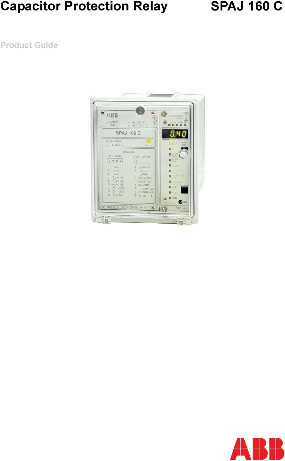
3 Issued: April 1999 Status: Updated Version: C/ Data subject to change without notice Features One-, two- and three-phase overload stage with definite time characteristic One-, two- and three-phase overload stage with inverse (ANSI) time characteristic Phase unbalance protection stage with definite time characteristic Phase unbalance protection stage with inverse time characteristic Undercurrent protection for detection of capacitor disconnection. Reconnection time with wide setting range Compensation for natural unbalance current Fully user-selectable output relay configuration Easy selection of appropriate operational scheme for various applications Numerical display of setting values, measured current values, memorized values, etc. Continuous self-supervision of hardware and software Serial interface for connecting the relay to the fibre-optic SPA bus and further to higher-level data acquisition, reporting and/or control systems Powerful software support for parameterization of the relay, for reading measured and recorded values, events, etc., and for storing readings Member of the SPACOM product family and ABB s Distribution Automation system CE marking according to the EC directive for EMC Application The numerical capacitor relay is an integrated current measuring multi-function relay designed to be used for the protection of capacitor banks. Capacitor banks are used in the power system for compensating the reactive power and for filtering harmonics. The capacitor banks are usually protected against overload caused by harmonic currents and overvoltage caused by internal faults in the bank. Protection against unintentional reconnection of a charged capacitor to an energized network is also to be included. All these functions are incorporated in the capacitor protection relay. A complete protection system for capacitor banks should also include overcurrent, short circuit and earth-fault protection. The capacitor protection relay is easily supplemented with adequate overcurrent and earth-fault relays from the SPACOM product range. 3

4 Design The capacitor protection relay includes a three-phase, two-stage overload unit, a twostage unbalance unit, an undercurrent unit and a reconnection inhibit timer. The relay measures the phase currents of the capacitor bank. The relay also measures the unbalance current of a split capacitor bank. The current transformer output can be adapted to the rated current of the relay by means of a matching setting. Equally, the unbalance unit is provided with a compensation feature which allows the natural unbalance current of a capacitor bank to be eliminated from the calculations. The phase currents measured by the relay are transformed to voltage images describing the voltages of the capacitor bank. Because harmonic components cause overloading of capacitor banks the relay measures harmonic components up to and including the 13th harmonic. The overload unit protects the capacitors against overvoltage. The first stage of the overload unit operates with inverse time operation characteristic, whereas the second overload protection stage has a definite time characteristic. The inverse time curve is based on ANSI/IEEE C37.99 and IEC recommendations for voltage withstand related to time for capacitor banks. The slope of the curve is adjustable. The unbalance unit is also provided with two operation stages. i.e. an inverse time stage according to BS 142 and a definite time stage. The former is normally used for tripping and the latter for signalling. The purpose of the undercurrent protection unit is to detect disconnection of the capacitor bank and to prevent a charged capacitor bank from being switched to the network. The start value, the operate time and the reconnection inhibit time are adjustable. The capacitor protection relay is provided with one external control input. The control input can be used for blocking one or more of the protection stages, for carrying out an external trip command, for inhibiting a reconnection attempt and/or for resetting a latched output relay in the manual reset mode of operation. Data communication The feeder protection relay is provided with a serial interface on the rear panel. By means of a bus connection module type SPA-ZC 21 or SPA-ZC 17 the feeder protection relay can be connected to the fibre-optic SPA bus. The bus connection module SPA-ZC 21 is powered from the host relay, whereas the bus connection module type SPA-ZC 17 is provided with a built-in power unit, which can be fed from an external secured power source. The relay communicates with higher-level data acquisition and control systems over the SPA bus. Self-supervision The relay incorporates a sophisticated selfsupervision system with auto-diagnosis, which increases the availability of the relay and the reliability of the system. The selfsupervision system continuously monitors the hardware and the software of the relay. The system also supervises the operation of the auxiliary supply module and the voltages generated by the module. When a permanent internal relay fault is detected, the IRF indicator on the relay front panel is lit. At the same time the output relay of the self-supervision system operates and a fault message is transmitted to the higherlevel system over the serial bus. Further, in most fault situations, a fault code is shown in the display of the protection relay module. The fault code indicates the type of the fault that has been detected. Auxiliary supply voltage The auxiliary supply of the relay is obtained from an internal plug-in type power supply module. Two auxiliary power module versions are available: type SPTU 240R2 for the supply voltage range V ac/dc and type SPTU 48R2 for the supply voltage range V dc. The power supply module forms the internal voltages required by the protection relay and the I/O module. 4

5 Technical data Table 1: Energizing inputs Phase current inputs 1-3, 4-6, , 4-5, 7-8 Unbalance current inputs Rated current I n 1 A 5 A Thermal current continuously 4 A 20 A withstand for 1 s 100 A 500 A Dynamic current Half-wave value 250 A 1250 A withstand Input impedance <100 mω <20 mω Phase current monitoring range x I n Phase unbalance current monitoring range 0 212% I n Rated frequency f n 50 Hz or 60 Hz Table 2: Output contact ratings Type of contact Tripping Signalling Terminals 65-66, , 68-69, 77-78, Rated voltage 250 V ac/dc Thermal withstand Carry continuously 5 A 5 A capability Make and carry for 0.5 s 30 A 10 A Make and carry for 3 s 15 A 8 A Breaking capacity for dc, 220 V dc 1 A 0.15 A when the control circuit 110 V dc 3 A 0.25 A time constant L/R 40 ms, at the control voltage levels 48 V dc 5 A 1 A Table 3: External control input Blocking and control input External control voltage level V dc or V ac Typical control current of activated input circuit 2 20 ma Table 4: Data communication Transmission mode Data code Transfer rates, selectable Optional bus connection for plastic core cables module, powered from for glass fibre cables an external power source Optional bus connection for plastic core cables module, powered from for glass fibre cables the host relay Fibre-optic serial bus ASCII 4800 or 9600 Bd SPA-ZC17BB SPA-ZC17MM SPA-ZC21BB SPA-ZC21MM 5

6 Technical data (cont d) Table 5: Capacitor protection relay module SPCJ 4D40 Overload stage I b > Start current I b > I n Start time <80 s Operation characteristic Time multiplier k Reset time ANSI inverse <100 ms Drop-off/pick-up ratio, typically 0.95 Operate time accuracy Operation accuracy ±3% of set value ±3% of set value Overload stage I a > Start current I a > % of I b > Undercurrent stage I< Phase unbalance I 1 > Phase unbalance I 2 > Unbalance compensation Operate time Reset time s <250 ms Drop-off/pick-up ratio, typically 0.95 Operate time accuracy ±2% of set value Operation accuracy ±3% of set value Start current I< I n Operate time s Reconnection inhibit time t rec min Reset time <80 ms Drop-off/pick-up ratio, typically 1.1 Operate time accuracy ±2% of set value or ±75 ms Operation accuracy within the range of I n ±3% of set value Start current I 1 > % of I n Operate time t s Reset time <100 ms Drop-off/pick-up ratio, typically 0.90 Operate time accuracy ±2% of set value or ±75 ms Operation accuracy within the range of % I n ±3% of set value Start current I 2 > % of I n Start time <70 s Operation characteristic Inverse time characteristic Time multiplier k Reset time <100 ms Drop-off/pick-up ratio, typically 0.90 Operate time accuracy of theoretical characteristic 7.5% or ±35 ms Operation accuracy ±3% of set value Shortest possible operate time ~100 ms Compensation current I cs % of I n Operation accuracy <3% of I n Table 6: Auxiliary supply modules Supply and output relay operative voltage range module SPTU 240R2 Supply and output relay operative voltage range module SPTU 48R2 Power consumption, quiescent/operation conditions V ac/dc V dc ~4 W/~6 W 6

7 Technical data (cont d) Table 7: Tests and standards Test voltages Dielectric test voltage (IEC ) 2.0 kv, 50 Hz, 1 min Interference tests Impulse test voltage (IEC ) Insulation resistance (IEC ) High-frequency (1 MHz) disturbance test (IEC ), common mode 5 kv, 1.2/50 µs, 0.5 J >100 MΩ, 500 V dc 2.5 kv High-frequency (1 MHz) disturbance 1.0 kv test (IEC ), differential mode Fast transients (IEC , class 4 kv, 5/50 ns III and IEC ), power supply inputs Fast transients (IEC , class 2 kv, 5/50 ns III and IEC ), other inputs Electrostatic discharge 8 kv (IEC and IEC ), air discharge Electrostatic discharge 6 kv (IEC and IEC ), contact discharge Environmental conditions Service temperature range C Transport and storage temperature C range (IEC ) Damp heat test (IEC ) <95%, 40 C, 56 d/a Degree of protection by enclosure IP 54 when panel mounted Weight ~3.5 kg 7
, differential mode Fast transients (IEC 60255-22-4, class 4 kv, 5/50 ns III and IEC 61000-4-4), power supply inputs Fast transients (IEC 60255-22-4, class 2 kv, 5/50 ns III")
8 Block diagram L1 L2 L I I 0 Rx Tx (~) Uaux - (~) IRF SIGNAL SIGNAALI LAUK. TRIP SPA-ZC_ UUDELLEEN- RECONNECTION KYTKENNÄN START HAVAHT. SIGNAALI SIGNAL 2 2 ENABLE SALLIMINEN CONTROL OHJAUS- INPUT TULO BS SERIAL SARJA- PORTTI 5 A 1 A 5 A 1 A 5 A 1 A 5 A 1 _ U3 - U2 SPTU_R2 F E D C B A TS1 SS1 SS2 SS3 TS2 1 LAUK. TRIP R SGB1/6 SGB1/7 SGB_/1 IRF 3Ia> 3Ib> T8 SGR1/1 SGR1/2 SGR1/3 SGR1/4 SGR2/1 SGR2/2 SGR2/3 SGR2/4 SGR2/5 SGR2/6 SGR2/7 SGR1/5 SGR1/6 SGR1/7 SGR1/8 SGR2/8 T2 SGF/1 T1 T3 SGB_/2 ÐI ÐI T4 T5 SGF/2 T6 SGB_/3 SGB_/4 SGB_/5 SGB_/8 3I< UUDELL.KYTK. RECONN.INHIBIT ESTO EXTERNAL ULK. LIIPAISU TRIP RELAY RELEENRESET KUITTAUS I/O U1 T7 T9 SPCJ 4D40 Fig. 1 Block diagram and sample connection diagram SJAJ160C_BLOCK.FH7 SPAJ160C_block 8

9 Mounting and dimensions Flush mounting ± ±1 Panel cutout dim100 Fig. 2 Flush-mounting relay case (dimensions in mm) Semi-flush mounting a b Raising frame SPA-ZX 111 SPA-ZX 112 SPA-ZX 113 a b SFM100_1 Fig. 3 Semi-flush mounting relay case (dimensions in mm) Mounting in 19 inch cabinets and frames An ancillary mounting plate, height 4U (~177 mm), is recommended to be used when the protection relays are to be mounted in 19 inch frames or cabinets. The ancillary mounting plate type SPA-ZX 104 accommodates three relays, type SPA-ZX 105 two relays and type SPA-ZX 106 one relay. Projecting mounting When projecting mounting is preferred, a relay case type SPA-ZX 110 is used. The relay case for projecting mounting is provided with front connectors. SPA-ZX104 SPA-ZX105 SPA-ZX106 0,4 482,6 0 (19") SPA-ZX110 SPA-ZX ø ,6 21,5 7 0, (4U) _6_10 Fig. 4 Mounting cabinets and frames as well as projecting mounting (dimensions in mm) 9

10 Ordering When ordering, please specify: Ordering information Ordering example 1. Type designation and quantity, 5 pieces 2. Order number RS AA 3. Rated values I n =5 A, f n =50 Hz 4. Auxiliary voltage U aux =110 V dc 5. Accessories - 6. Special requirements - Order numbers Capacitor protection relay without test adapter Capacitor protection relay including test adapter RTXP 18 The last two letters of the order number indicate the rated frequency f n and the auxiliary voltage U aux of the relay as follows: RS AA, CA, DA, FA RS AA, CA, DA, FA AA equals f n = 50 Hz and U aux = V ac/dc CA equals f n = 50 Hz and U aux = V dc DA equals f n = 60 Hz and U aux = V ac/dc FA equals f n = 60 Hz and U aux = V dc References Additional information Manual Capacitor bank overload and unbalance protection relay 1MRS MUM EN 10

11

12 ABB Oy Distribution Automation P.O. Box 699 FI Vaasa, FINLAND Tel Fax

Voltage Regulator SPAU 341 C. Product Guide
 Issued: July 1998 Status: Updated Version: D/25.04.2006 Data subject to change without notice Features Comprehensive voltage regulation for power transformers with on-load tapchangers in distribution substations
Disturbance Recoder SPCR 8C27. Product Guide
 Issued: April 1999 Status: Updated Version: C/26.04.2006 Data subject to change without notice Features Versatile digital disturbance recorder module for recording various phenomena in the electric power
Remote Monitoring and REC 501 Control Unit Product Guide
 Remote Monitoring and Control Unit REC 501 Product Guide Issued: May 1999 Status: Updated Version: B/06.11.2001 Data subject to change without notice Features Remote control and monitoring unit for the
Arc Protection Relay REA 10_. Product Guide
 Arc Protection Relay REA 10_ Product Guide Issued: 1May 1999 Status: Updated Version: D / 22.06.2005 Data subject to change without notice Features Loop-type sensor fiber, radial sensor fiber or lens-type
Combined overcurrent & earth-fault relay. Type SPAJ 140 C
 Combined overcurrent & earth-fault relay Type SPAJ 140 C ABB a global technology leader ABB is a global leader in Power and Automation technologies that enable utility and industry customers to improve
SPAM 150 C. Motor protection relay SPAM 150 C. User s manual and Technical description. U aux 18...80V NC. θ>θ t. θ [ % ] 9 EXT.TRIP I >> / I.
![SPAM 150 C. Motor protection relay SPAM 150 C. User s manual and Technical description. U aux 18...80V NC. θ>θ t. θ [ % ] 9 EXT.TRIP I >> / I.](/thumbs/39/18513453.jpg "SPAM 150 C. Motor protection relay SPAM 150 C. User s manual and Technical description. U aux 18...80V NC. θ>θ t. θ [ % ] 9 EXT.TRIP I >> / I.") SPAM 50 C Motor protection relay User s manual and Technical description I n = A 5A ( I ) I n = A 5A ( I o) f n = 50Hz 60Hz 5 3I >> 3 I I L I L I L3 I o IRF SPAM 50 C 80...65V ~ NO 8...80V NC REGISTERS
SPAM 50 C Motor protection relay User s manual and Technical description I n = A 5A ( I ) I n = A 5A ( I o) f n = 50Hz 60Hz 5 3I >> 3 I I L I L I L3 I o IRF SPAM 50 C 80...65V ~ NO 8...80V NC REGISTERS
REA 10_ 1MRS 750929-MBG
 Arc protection relay REA 10_ Issued: May 1999 Status: Updated Version: C/05.07.2002 Data subject to change without notice Features Loop-type sensor fibre, radial sensor fibre or lens-type sensor for arc
Current and voltage measuring relays
 Current and voltage measuring relays RXIK 1, RXEEB 1 and Page 1 Issued June 1999 Changed since July 1998 Data subject to change without notice RXIK 1 RXEEB 1 (SE980082) (SE980081) (SE970869) Features Application
Relion 605 series. Self-powered feeder protection REJ603 Product Guide
 Relion 605 series Relion 605 series Relion 605 series Self-powered feeder protection Product Guide Product version: 3.0 Contents 1.... 3 2. Relay functions... 3 3. Protection functions... 4 4. Application...
Trip circuit supervision relay. Type RXTCS
 Trip circuit supervision relay Type RXTCS ABB a global technology leader ABB is a global leader in Power and Automation technologies that enable utility and industry customers to improve performance while
Overcurrent and earth-fault relay
 SPAJ 40 C Overcurrent and earth-fault relay User s manual and Technical description f n = 50Hz 60Hz I n = A I n = A 5A 5A ( I ) ( I o) 5 3 I > I I L I L I L3 I 0 IRF REGISTERS SPAJ 40 C SPCJ 4D9 0 0 0
Circulating Current Relay. Type IRXm
 Circulating Current Relay Type IRXm ABB a global technology leader ABB is a global leader in Power and Automation technologies that enable utility and industry customers to improve performance while lowering
Three-phase monitoring relay CM-PFE
 Data sheet Three-phase monitoring relay CM-PFE The CM-PFE is a three-phase monitoring relay that monitors the phase parameter phase sequence and phase failure in three-phase mains. 2CDC 251 005 S0012 Characteristics
Waveguide Access Point WGA631. Product Guide
 Waveguide Access Point Product Guide Waveguide Access Point Contents 1. Description............................ 3 2. Application............................ 3 3. Technical data... 4 4. Physical interfaces......................
Quick Connect. quick - simple - efficient. www.g-mw.de
 Quick Connect quick - simple - efficient www.g-mw.de Phone: +49 9103 7129-0 Fax: +49 9103 7129-207 Innovative connection technology to plug three single-phase current transformers to multifunctional power
RM4TG20 three-phase network control relay RM4-T - range 200..500 V
 Characteristics three-phase network control relay RM4-T - range 200..500 V Complementary [Us] rated supply voltage Output contacts Setting accuracy of time delay Delay at power up Measuring cycle Marking
REA 101 Arc protection relay. Operator s manual
 REA 101 1MRS 751003-MUM Issued: 08.04.1998 Version: C/19.10.2000 Checked: Approved: REA 101 We reserve the right to change data without prior notice. Contents: 1. General...5 1.1. Features...5 2. Safety...6
Electronic timer CT-VBS.17+18 OFF-delayed without auxiliary voltage, for DC contactors Data sheet
 Characteristics Single-function OFF-delay timer for DC contactors, without auxiliary voltage Width.5 mm CDC 5 6 F3 Approvals A culus E CCC CT-VBS a Circuit diagram b Marker label Marks a CE b C-Tick Order
ABB 1. Three-phase monitoring relay CM-PFS. Data sheet. Features. Approvals. Marks. Order data. Order data - Accessories. Application.
 1SR 430 824 F9300 Features Monitoring of three-phase mains for phase sequence and failure Powered by the measuring circuit 2 c/o (SPDT) contacts 1 LED for status indication Approvals R: yellow LED - relay
Safety technique. Emergency stop module BO 5988 safemaster
 Safety technique Emergency stop module BO 5988 safemaster 0221562 Function diagram Pushbutton on Mains or emergencystop () K1 According to EC Directive for machines 98/37/EG According to IEC/E 60204-1
Electronic timer CT-AHD.12 OFF-delayed with 1 c/o (SPDT) contact
 contact") Data sheet Electronic timer CT-AHD.12 OFF-delayed with 1 c/o (SPDT) contact The CT-AHD.12 is an electronic time relay with OFF-delay. It is from the CT-D range. With their MDRC profile and a width of only
Data sheet Electronic timer CT-AHD.12 OFF-delayed with 1 c/o (SPDT) contact The CT-AHD.12 is an electronic time relay with OFF-delay. It is from the CT-D range. With their MDRC profile and a width of only
Voltage monitoring relays CM-ESS.2 For single-phase AC/DC voltages
 Data sheet Voltage monitoring relays CM-ESS.2 For single-phase AC/DC voltages The CM-ESS.2 is an electronic voltage monitoring relay that provides reliable monitoring of voltages as well as detection of
Substation Automation Products Relion 670/650 series IEC and ANSI Hardware
 Substation Automation Products Relion 670/650 series IEC and ANSI Hardware ABB Group 1MRG014097 October 2013 Relion 670/650 series hardware Contents Relion 670/650 series Relion Hardware Relion Common
Relion 605 series. Feeder protection and control / Feeder protection REF601 / REJ601 Product Guide
 Relion 605 series Feeder protection and control / Feeder protection Product Guide Product version: 2.2FP1 Contents 1. Description... 3 2. Relay functions... 3 3. Protection functions... 4 4. Application...
RM17TE 183...528 V AC. Main. Product or component type. Product specific application. Relay monitored parameters 250 V DC 5 A DC
 Characteristics multifunction control relay RM17-TE - range 183..528 V AC Complementary Reset time Maximum switching voltage Minimum switching current Maximum switching current [Us] rated supply voltage
ABB 1 NEW. Three-phase monitoring relay for grid feeding CM-UFS.1. Data sheet. Features. Approvals. Marks. Order data. Order data - Accessories
 2CDC 251 014 F0t09 Features Monitoring of three-phase mains for grid feeding Type-tested in accordance with DIN V VDE V 0126-1-1: February 2006 Neutral conductor connection configurable Can also be used
Pilot-wire differential relay for lines with two or more terminals
 Pilot-wire differential relay for lines with two or more terminals Page 1 Issued: March 2003 Revision: A Data subject to change without notice Pilot-wire differential relay with RXHL 401 Features Phase
38 Series - Relay interface modules 0.1-2 - 3-5 - 6-8 A
 38 Series - Relay interface modules 0.1-2 - 3-5 - 6-8 A Common features Instant ejection of relay by plastic retaining clip Integral coil indication and protection circuit EMR Electromechanical Relays
80 Series - Modular timers 16 A. Features 80.01 80.11
 80 Series - Modular timers 16 A Features 80.11 Multi-function and mono-function timer range - Multi-function & multi-voltage 80.11 - On-delay, multi-voltage 17.5 mm wide Six time scales from 0.1s to 24h
38 SERIES. Relay interface modules 0.1-2 - 3-5 - 6-8 - 16 A. EMR Electromechanical Relays. Common features. SSR Solid State Relays. 6.
 38 Relay interface modules 0.1-2 - 3-5 - 6-8 - 16 A 38 Common features Instant ejection of relay by plastic retaining clip Integral coil indication and protection circuit 6.2 mm wide EMR - DC, AC or AC/DC
Voltage monitoring relays CM-ESS.M For single-phase AC/DC voltages
 Data sheet Voltage monitoring relays CM-ESS.M For single-phase AC/DC voltages The CM-ESS.M is an electronic voltage monitoring relay that provides reliable monitoring of voltages as well as detection of
Features. Display. Measurements. Intelligent. Accuracy. Models. Installation DEIF A/S. Multi-instrument 4921210109D
 7000/7000C/7020 Multi-instrument 4921210109D Features Measurements All 3-phase AC measurements True RMS Replaces analogue meters Demand on each phase current Accuracy U, I and F class 0.5 Other values
MasterINTERFACE 39 Series - Relay interface modules
 MasterINTERFACE 39 Series - Relay interface modules Common features Space saving 6.2 mm wide Connections for 16-way jumper link Integral coil indication and protection circuit Secure retention and easy
Low Voltage Products. Switches Automatic Transfer Switches
 Low Voltage Products Switches Automatic Transfer Switches Growing importance of a secure power supply Standby power is an integral part of many industrial and domestic electrical systems. High energy prices,
Analog signal converters CC-E I/I Current / current isolators
 ata sheet Analog signal converters CC-E I/I Current / current isolators The CC-E I/I is an isolator for the electrical isolation of current signals without auxiliary supply. It allows the isolation between
Type: EASY719 DC RC Article No.: 274119. Ordering information Relay outputs Quantity 6 Power supply V DC 24 V DC. Description
 Type: EASY719 DC RC Article.: 274119 Ordering information Relay outputs Quantity 6 Power supply V DC 24 V DC Description 12 digital inputs (4 inputs available as analog inputs) 6 relay outputs LCD display
T 3000. Substation Maintenance and Commissioning Test Equipment
 T 3000 Substation Maintenance and Commissioning Test Equipment Multi function system for testing substation equipment such as: current, voltage and power transformers, all type of protection relays, energy
38 Series - Relay interface modules 0.1-2 - 3-5 - 6-8 - 16 A
 38 Series - Relay interface modules 0.1-2 - 3-5 - 6-8 - 16 A 38 SERIES Common features Instant ejection of relay by plastic retaining clip Integral coil indication and protection circuit EMR Electromechanical
Arc Protection Relay REA 101. Operator s Manual
 Arc Protection Relay 1MRS751003-MUM Issued: 08.04.1998 Version: F/23.06.2005 Arc Protection Relay 1. About this manual...5 1.1. Copyrights...5 1.2. Trademarks...5 1.3. Guarantee...5 1.4. General...5 1.5.
DRTS 33. The new generation of advanced test equipments for Relays, Energy meters, Transducers and Power quality meters
 The new generation of advanced test equipments for Relays, Energy meters, Transducers and Power quality meters Testing all relay technologies: electromechanical, solid state, numerical and IEC61850 Manual
Three-phase monitoring relays CM-PSS CM-PSS.31 and CM-PSS.41
 Data sheet Three-phase monitoring relays CM-PSS CM-PSS.31 and CM-PSS.41 The three-phase monitoring relays CM-PSS.x1 monitor the phase parameters phase sequence, phase failure as well as over- and undervoltage.
Temperature monitoring relays CM-TCS Monitoring relays for monitoring temperatures with a PT100 sensor (2- or 3-wire connection)
") Data sheet Temperature monitoring relays CM-TCS Monitoring relays for monitoring temperatures with a PT100 sensor (2- or 3-wire connection) The temperature monitoring relays CM-TCS monitor overtemperature,
Data sheet Temperature monitoring relays CM-TCS Monitoring relays for monitoring temperatures with a PT100 sensor (2- or 3-wire connection) The temperature monitoring relays CM-TCS monitor overtemperature,
ABB i-bus KNX SA/S Switch Actuators Product Manual
 ABB i-bus KNX SA/S Switch Actuators Product Manual Contents Contents Page 1 General... 5 1.1 Using the product manual...5 1.1.1 Structure of the product manual...6 1.1.2 Notes...6 1.2 Product and functional
Thermistor motor protection relays CM-MSS.22 and CM-MSS.23
 Data sheet Thermistor motor protection relays CM-MSS.22 and CM-MSS.23 The thermistor motor protection relays CM-MSS.22 and CM-MSS.23 monitor the winding temperature of motors and protect them from overheating,
Bulletin 150 Smart Motor Controllers SMC-3 Smart Motor Controller
 Overview/Modes of Operation Bulletin 150 Smart Motor Controller The SMC-3 is a compact, simple to use, solid-state motor controller designed to operate 3-phase motors. It features a built-in overload relay
Both variants can be used for measuring the positive sequence voltage Up or the negative sequence voltage Un.
 Rev. - 2004-10-22 Page 1(5) General RXTBA 1 is a three-phase phase sequence voltage filter built up by resistors and capacitors. The filter is available in two voltage variants; one for rated voltage 3x110
Power-monitoring unit PowerLogic System. Technical data sheet. Power Meter Series 800
 Power-monitoring unit PowerLogic System Technical data sheet 2003 Power Meter Series 800 Function and characteristics PB100313 The PowerLogic Power Meter Series 800 offers all the high-performance measurement
Power factor correction and harmonic filtering. Rectimat 2 Automatic capacitor banks. Catalogue. Building a New Electric World
 Catalogue 2002 Automatic capacitor banks Building a New Electric World 0Contents Power factor correction 2 Power factor equipment selection guide 3 General technical data 4 Capacitors and banks 50 z 6
Positive-guided relay outputs: 3 safety contacts (N/O), instantaneous. 1 auxiliary contact (N/C), instantaneous
, instantaneous. 1 auxiliary contact (N/C), instantaneous") Safety relay for monitoring E-STOP pushbuttons. Approvals Unit features Positive-guided relay outputs: 3 safety contacts (N/O), instantaneous 1 auxiliary contact (N/C), instantaneous Safe separation of
Safety relay for monitoring E-STOP pushbuttons. Approvals Unit features Positive-guided relay outputs: 3 safety contacts (N/O), instantaneous 1 auxiliary contact (N/C), instantaneous Safe separation of
48 SERIES Relay interface modules 10 A
 48 Relay interface modules 10 A 1 CO relay interface modules, mm wide Ideal interface for PLC and electronic systems Type 48.P3 1 CO 10 A s Type 48.31 1 CO 10 A s AC coils or DC sensitive coils Supply
Thermistor motor protection
 Thermistor motor protection CM-E Range Thermistor motor protection Thermistor motor protection relays Benefits and advantages Selection table Operating principle and fields of application for thermistor
MasterINTERFACE 39 Series - Relay interface modules
 MasterINTERFACE 39 Series - 39 Common features Space saving 6.2 mm wide Connections for 16-way jumper link Integral coil indication and protection circuit Secure retention and easy ejection by plastic
Digital Pressure Measuring Instrument MDR480
 Description The digital panel instrument MDR480 is designed to measure, display, and monitor pressures in industrial applications. The instrument is panel mounted with a front frame dimension of 96 mm
Electronic overload relay EF65, EF96 and EF146
 Data sheet Electronic overload relay EF65, EF96 and EF146 Electronic overload relays offer reliable protection in case of overload and phase-failure. They are the alternative to thermal overload relays.
FREJA 300 Relay Testing System
 Relay Testing System A Megger Group Company FREJA 300 Relay testing system The FREJA 300 relay testing system is a computer-aided relay testing and simulation system. The weight of FREJA 300 is only 15
MONITORING RELAYS. w VOLTAGE MONITORING RELAY UR5U1011. w SCHRACK-INFO. w TECHNICAL DATA
 w VOLTAGE MONITORING RELAY UR5U1011 w SCHRACK-INFO AC/DC voltage monitoring in 1-phase mains Undervoltage monitoring 1 change over contact Width 17.5 mm Installation design w TECHNICAL DATA 502 1. Functions
Voltage monitoring relays CM-ESS.2 For single-phase AC/DC voltages
 Data sheet Voltage monitoring relays CM-ESS.2 For single-phase AC/DC voltages The CM-ESS.2 is an electronic voltage monitoring relay that provides reliable monitoring of voltages as well as detection of
Power Supply Unit, Primary Switched, Narrow Design MINI-PS-12-24DC/24DC/1
 Power Supply Unit, Primary Switched, Narrow Design MINI POWER provides: Extra narrow design with widths of 22.5 mm, 45 mm, and 67.5 mm (0.886, 1.772, and 2.657 in.) Global use due to a wide-range input
Electronic overload relay EF19 and EF45
 Data sheet Electronic overload relay EF19 and EF45 Electronic overload relays offer reliable protection in case of overload and phase-failure. They are the alternative to thermal overload relays. Motor
Power Meter Series 700
 PowerLogic power-monitoring units Power Meter Series 700 Technical data sheet 2007 Functions and characteristics E90463 The PowerLogic Power Meter Series 700 offers all the measurement capabilities required
AC3200 INTELLIGENT BROADBAND AMPLIFIER
 Kari Mäki 9.4.2013 1(7) AC3200 INTELLIGENT BROADBAND AMPLIFIER AC3200 is the latest leading-edge addition to AC family with extended frequency and gain ranges and integrated electrical controls in both
A project to optimise quality and energy efficiency must include metering
 EMDX 3 : Energy Metering A project to optimise quality and energy efficiency must include metering Metering upstream identifies the critical points and ensures optimum targeting of the actions to be taken,
60 Series - General purpose relays 6-10 A. Features 60.12 60.13
 Features 60.12 60.13 Plug-in mount 10 A General purpose relay 2 & 3 pole changeover contacts Cadmium Free contacts (preferred version) AC coils & DC coils UL Listing (certain relay/socket combinations)
ABB i-bus KNX Switch Actuator, x-fold, 16/20 A, MDRC SA/S x.16.6.1, 2CDG 110 1xx R0011
 , 2CDG 110 1xx R0011 SA/S 8.16.6.1 2CDC 071 006 S0010 The 16/20 A Switch actuators are modular installation devices in Pro M Design for installation in the distribution board. The devices are especially
instabus KNX / EIB System System E F G H
 Product name: Uninterruptible power supply (USV) 640 ma Design: REG (rail-mounted device) Article-no.: 1079 00 ETS search path: Gira Giersiepen / system components / power supply / power supply 640mA DRA
80 Series - Modular timers 16 A. Features 80.01 80.11
 80 Series - Modular timers 6 A 80. Multi-function and mono-function timer range - Multi-function & multi-voltage 80. - ON delay, multi-voltage 7.5 mm wide Six time scales from 0.s to 24h 35 mm rail (EN
HSP GmbH Zum Handwerkerhof 2 90530 Wendelstein Tel. 09129 / 2852-0 Fax: 09129 / 2852-11 Web: www.hsshsp.de EMAIL: [email protected] NTG-3000.
 NTG-3000 Transducer Data Sheet Document Version 2.8 Page 1 of 10 Versions / Revisions: Document Creation Author Description version date 2.0 2012-07-25 P. Compensis First official version 2.1 2012-08-24
Single-phase (220...240 V) voltage monitoring: Undervoltage Overvoltage Window mode (overvoltage + undervoltage) Voltage fault memory selectable
 voltage monitoring: Undervoltage Overvoltage Window mode (overvoltage + undervoltage) Voltage fault memory selectable") Features 70.11 70.31 70.41 Electronic voltage monitoring relays for single and three-phase applications Multifunctional types, providing the flexibility of monitoring Undervoltage, Overvoltage, Window
Features 70.11 70.31 70.41 Electronic voltage monitoring relays for single and three-phase applications Multifunctional types, providing the flexibility of monitoring Undervoltage, Overvoltage, Window
RM35UA13MW. range 15..600 V. Main. Product or component type. Relay monitored parameters
 Characteristics multifunction voltage control relay RM35-U - range 15..600 V Complementary Reset time Maximum switching voltage [Us] rated supply voltage Supply voltage limits Power consumption in W Main
Bulletin 150 SMC Flex Smart Motor Controller Specifications
 Specifications Specifications Standard Features Optional Features Installation Setup Communications Power Wiring Control Wiring Keypad Software Starting and Stopping Modes Protection and Diagnostics Metering
PD30ETB20xxIS. Photoelectrics, Background Suppression reflective with IR light. Main features. Description
 Photoelectrics, Background Suppression reflective with IR light Main features Description The PD30ET... stainless steel sensors are built with high-quality materials and designed for harsh environments.
RISH CON - Hz. Salient Features : Application : Product Features: FREQUENCY TRANSDUCER
 Application : The RISH CON - Hz transducer is used for frequency measurement. The output signal is proportional to measured frequency and is either load independent DC Current or load independent DC Voltage.
Pluggable interface relays CR-P Pcb relays
 2CDC 293 034 F0004 1 2 4 3 Features 9 different supply s: DC versions: 12 V, 24 V, 48 V, 110 V AC versions: 24 V, 48 V, 110 V, 120 V, 230 V Output contacts: 1 c/o (16 A) or 2 c/o (8 A) Cadmium-free contact
Portal Software GSM-PRO Run LED displays module activity Com LED displays activity on the GSM network GSM-PRO
 GSM-PRO GSM-PRO perfect for communication CONTA-CLIP s GSM-PRO module offers a remote control and maintenance solution which allows you to monitor and control decentralized facilities. The GSM-PRO module
Thermal-Magnetic Circuit Breaker 3120-...-M1-..
 Thermal-Magnetic Circuit Breaker -...-M-.. Description Single or two pole rocker switch/thermal-magnetic circuit breaker with trip-free mechanism (S-type TM CBE to EN 34). The addition of a magnetic tripping
Energy Management Energy Meter Type EM23 DIN
 Energy Management Energy Meter Type EM23 DIN Class 1 (kwh) according to EN62053-21 Class B (kwh) according to EN50470-3 Class 2 (kvarh) according to EN62053-23 Accuracy ±0.5 RDG (current/voltage) Energy
Product and Applications Description. Application Programs. Example of Operation. GAMMA instabus Technical Product-Information.
 Product and Applications Description The power supply units N 125/x2 can supply DC 24 V power from an additional pair of terminals (yellowwhite). This DC 24 V output voltage can be used to power e.g. an
Technical data. General specifications. Indicators/operating means. 30 Hz Multiplex operation 30 Hz / n, n = number of sensors, n 5
 Model Number Single head system Features Parameterization interface for the application-specific adjustment of the sensor setting via the service program ULTRA 000 programmable switch outputs Hysteresis
MICROSENS. Central 48 V DC Power Supplies for PoE-Components. Description. Features
 Central 48 V DC Power Supplies for PoE-Components MICROSENS Description Active network equipment which is supporting the Power-over-Ethernet functions, typically requires a powerful 48 V DC power supply.
Instruction Bulletin. MCS025 Sync-Check Module Installation Sheet
 Instruction Bulletin 63230-216-244B1 LaVergne, TN, USA MCS025 Sync-Check Module Installation Sheet Retain for future use. DANGER HAZARD OF ELECTRIC SHOCK, EXPLOSION, OR ARC FLASH Only qualified electrical
Operating Manual for the Electronic Built-in Interval Timer. Micro II (Countdown Timer)
") Operating Manual for the Electronic Built-in Interval Timer Micro II (Countdown Timer) Note: This document has been designed for our OEM customers. They can use it as supporting material when creating
Operating Manual for the Electronic Built-in Interval Timer Micro II (Countdown Timer) Note: This document has been designed for our OEM customers. They can use it as supporting material when creating
Inductive Sensors Single or Dual Loop Detectors Type LD with teach-in
 Inductive Sensors Single or Dual Loop Detectors Type LD with teach-in Single or Dual loop detector Automatically adjustment of detection level Manual sensitivity for compensations of variations Easy installation
Thyristor-controlled power supplies and battery chargers
 Thyristor-controlled power supplies and battery chargers Input voltage: 115 / 230 VAC, single phase, 50 / 60 Hz or 208 / 400 / 480 VAC, three phases, 50 / 60 Hz Output voltage: 12 / 24 / 48 / 60 / 72 /
ELR: ABB range of front panel residual current relays Protection device according to IEC/EN 60947-2 Annex M
 ELR: ABB range of front panel residual current relays Protection device according to IEC/EN 60947-2 Annex M Tested, certified, reliable Network monitoring and protection The electronic residual current
Rack mounted telephone- and leased line modem for industrial applications
 Rack mounted telephone- and leased line modem for industrial applications TR-6 Rack modem for industrial PSTNand /-wire leased line applications The TR-6 is an analogue V. 9 -rack PSTN modem as well as
Number 1 in efficiency
 PowerXL DE1 Variable Speed Starter www.eaton.eu/de1 Number 1 in efficiency The easiest way of variable motor speed NEW Variation DE11 The new device category! The PowerXL DE1 Variable Speed Starter Why
TRACTION NETWORK MONITORING AND PROTECTION SYSTEM SMTN-3 CITY ELECTRIC TRANSPORT RAILWAYS METRO INDUSTRY
 TRACTION NETWORK MONITORING AND PROTECTION SYSTEM SMTN-3 CITY ELECTRIC TRANSPORT RAILWAYS METRO INDUSTRY 2 TRACTION NETWORK MONITORING AND PROTECTION SYSTEM Traction network monitoring and protection system,
Technical catalogue. Modular DIN rail components Installation contactors
 Technical catalogue Modular DIN rail components Installation contactors Installation Contactors Overview... ESB Installation Contactors 0 A / AC-/AC-7a ESB0...4 4 A / AC-/AC-7a ESB4...5 40 A / AC-/AC-7a
RISH EM 3490 DS Dual Source Energy Meter RISH EM 3490 DS. Application : Product Features:
 Application : RISH Master 3490 DS measures important electrical parameters of Utility (in normal mode) & Generators (in Power back up) in three phase and single phase Network & replaces the multiple analog
0.8 U N /0.5 U N 0.8 U N /0.5 U N 0.8 U N /0.5 U N 0.2 U N /0.1 U N 0.2 U N /0.1 U N 0.2 U N /0.1 U N
 55 Series - General purpose relays 7-10 A Features 55.12 55.13 55.14 Printed circuit mount, general purpose 2, 3 & 4 Pole relays 55.12-2 Pole 10 A 55.13-3 Pole 10 A 55.14-4 Pole 7 A AC coils & DC coils
49 Series - Relay interface modules 8-10 - 16 A. Features
 Features 1 & 2 Pole relay interface modules 5 µm Gold plate contacts for low level switching capability 49.31-50x0-1 Pole 10 A (screw terminal) 49.52-50x0-2 Pole 8 A (screw terminal) 49.72-50x0-2 Pole
Feeder Protection Relay. Technical Reference Manual - ANSI Version
 1MRS755535 Issued: 30.01.2005 Version: E/18.11.2011 Contents Copyrights... 7 1. Introduction...9 1.1. This manual... 9 1.2. Use of symbols... 9 1.3. Intended audience... 9 1.4. Product documentation...
Magnetic and Hydraulic-Magnetic Circuit Breaker 8340-G2...
 Magnetic and Hydraulic-Magnetic Circuit Breaker 840-G2... Description Single, two and three pole magnetic circuit breakers with trip-free mechanism and push/pull on/off manual actuation. A choice of fast
Installation manual. Generator Paralleling Controller GPC multi-line 2 4189340225C
 Installation manual Generator Paralleling Controller GPC multi-line 2 Software ver. 1.3X Compact system in one unit - dynamic synchronisation - load sharing - generator protection DEIF A/S 3-phase AC RMS
Process modules Digital input PMI for 24 V DC inputs for 120 V AC inputs
 E031026 000823 Process modules Digital input PMI for inputs for 120 V AC inputs PMI Input E4, E5, GND L- PMI 120 V AC Input E4, E5, Common C E6, E7, GND L- E6, E7, Common C LEDs for the inputs operation
LC1D65AM7 TeSys D contactor - 3P(3 NO) - AC-3 - <= 440 V 65 A - 220 V AC coil
 - AC-3 - <= 440 V 65 A - 220 V AC coil") Product data sheet Characteristics LC1D65AM7 TeSys D contactor - 3P(3 NO) - AC-3 -
Product data sheet Characteristics LC1D65AM7 TeSys D contactor - 3P(3 NO) - AC-3 -
Feeder protection. for overhead lines and cables in isolated neutral or compensated networks. Specification
 Feeder protection for overhead lines and cables in isolated neutral or compensated networks Specification Feeder protection for overhead lines and cables in isolated neutral or compensated networks Version
Applications. diris_826_a_1_gb_cat
 Measurement units NEW diris_824_a_1_cat Energy monitoring and management of low voltage/ high voltage electrical installations Function are measurement units which can provide all the functions offered
Technical data. General specifications. Indicators/operating means. Electrical specifications Operating voltage U B Power consumption P 0 Interface
 Release date: 06-0- 09: Date of issue: 06-0- 009_eng.xml Model Number Single head system Features Parameterization interface for the application-specific adjustment of the sensor setting via the service
Relés e Contatores de Estado Sólido SIRIUS
 Relés e Contatores de Estado Sólido SIRIUS Coletânea de dados técnicos ( product data sheet ) Agosto/212 SSR - 3RF21 22,5 mm Ponto Zero SSR - 3RF2 45 mm Ponto Zero SSR - 3RF22 45 mm Ponto Zero Trifásico