BASIC CONCEPTS AND CONVENTIONAL METHODS OF STUCTURAL ANALYSIS (LECTURE NOTES)
|
|
|
- Brice Allison
- 8 years ago
- Views:
Transcription
1 BASIC CONCEPTS AND CONVENTIONA METHODS OF STUCTURA ANAYSIS (ECTURE NOTES) DR. MOHAN KAANI (Retired Professor of Structural Engineering) DEPARTMENT OF CIVI ENGINEERING INDIAN INSTITUTE OF TECHNOOGY (BOMBAY) POWAI, MUMBAI , INDIA

2 ACKNOWEDGEMENTS I realize the profound truth that He who created all things inert as well as live is GOD. But many things in this world are created through knowledge of some living beings and these living beings are groomed by their teachers and through their own effort of self study and practice. Those who are gifted by God are exceptions and those who are gifted by their teachers are lucky. I am thankful to God as He has been grateful to me much more than I deserve and to my all teachers from school level to University heights as I am product of their efforts and guidance and hence this work. It is not out of place to mention some names that did excellent job of teaching and showed path to learning, teaching and research. Mr. Sainani of Baba Thakurdas Higher Secondary School, ucknow, India did excellent job of teaching of mathematics at school level. Mr. Tewarson of ucknow Christian College, ucknow, India was an excellent teacher of mathematics at college level. Professor Ramamurty taught theory of Structures excellently at I.I.T. Kharagpur, India. Visiting Professor Paul Andersen from U.S.A. demonstrated the techniques of teaching through his very well prepared lectures and course material on Structural Mechanics, Soil Mechanics and his consultancy practice. Visiting Professor Gerald Picket taught Advanced Theory of Elasticity, Plates and shells. It was a rare opportunity to be their student during Master of Engineering Course of Calcutta University at Bengal Engineering College, Howrah, India. During my Ph.D. programme at eningrad Plytechnic Institute, eningrad (St. Petersberg), Russia, Professor.A. Rozin, Head of Department of Structural Mechanics and Theory of Elasticity presented lectures and course material on Matrix Methods of Finite Element Analysis excellently. The present work is the result of inspirations of my teachers and also any future work that I may accomplish. ast but not the least, I express my gratitude to Professor Tarun Kant, Present Dean (Planning) I.I.T. Powai, Mumbai India and Ex. Head of Civil Engineering Department who extended the facility of putting this work on web site of I.I.T. Powai, Mumbai, India. Also I thank present Head of Civil engineering Department, I.I.T. Powai, India. Professor G.Venkatachalam who whole heatedly extended the facility of typing this manuscript in the departmental library by Mrs. Jyoti Bhatia and preparation of figures in the drawing office by Mr. A.J. Jadhav and Mr. A.A. Hurzuk. Above all I am thankful to Professor Ashok Misra, Director of I.I.T. Powai, Mumbai, India who has a visionary approach in the matters of theoretical and practical development of knowledge hence, the I.I.T. employees in service or retired get the appropriate support from him in such matters. He has the plans to make I.I.T. Powai the best institute in the world.

3 The inspiration and knowledge gained from my teachers and literature have motivated me to condense the conventional methods of structural analysis in this work so that a reader can get the quick insight into the essence of the subject of Structural Mechanics. In the end I wish to acknowledge specifically the efforts of Mrs. Jyoti Bhatia, who faithfully, sincerely and conscientiously typed the manuscript and perfected it as far as possible by reviewing and removing the errors. Finally I thank Sri Anil Kumar Sahu who scanned all the figures and integrated the same with the text and arranged the entire course material page wise.

4 REFERENCES 1. Andersen P. Statically Indeterminate Structures. The Ronald Press Company, New York, U.S.A, Darkov A & Kuznetsov V. Structural Mechanics. Mir Publishers, Moscow, Russia. 3. Junnarkar S.B. Mechanics of Structures, Valumes I & II. Chartor Book Stall, Anand, India. 4. Mohan Kalani. Analysis of continuous beams and frames with bars of variable crosssection. I. Indian Concrete Journal, March Mohan Kalani. Analysis of continuous beams and frames with bars of variable crosssection :. Indian Concrete Journal, November Norris C.H., Wilbur J.B & Utku S. Elementary Structural Analysis. McGraw Hill Book Company, Singapore. 7. Raz Sarwar Alam. Analytical Methods in Structural Engineering. Wiley Eastern Private imited, New Delhi, India. 8. Timoshenko S.P & Young D.H. Theory of Structures. McGraw Hill Kogakusha td., Tokyo, Japan. 9. Vazirani V.N. & Ratwani M.M. Analysis of Structures, Khanna Publishers, Delhi, India. 10. West H.H. Analysis of Structures. John Wiley & Sons, New York, USA.

5 CONTENTS CHAPTER TOPIC PAGE NO 1. INTRODUCTION 1. CASSIFICATION OF SKEEA OR FRAMED STRUCTURES 1 3. INTERNA OADS DEVEOPED IN STRUCTURA MEMBERS 4. TYPES OF STRUCTURA OADS 3 5. DTERMINATE AND INDETERMINATE 4 STRUCTURA SYSTEMS 6. INDETERMINACY OF STRUCTURA SYSTEM 7 7. FEXIBIITY AND STIFFNESS METHODS ANAYSIS OF STATICAY DETERMINATE STRUCTURES 1 9. ANAYSIS OF DETERMINATE TRUSSES CABES AND ARCHES INFUENCE INES FOR DETERMINATE STRUCTURES 3 1. DEFECTION OF STRUCTURES NONPRISMATIC MEMBERS SOPE DEFECTION EQUATIONS MOMENT DISTRIBUTION METHOD 58

6 16. ANAYSIS OF CONTINUOUS BEAMS AND PANE FRAMES CONSISTING OF PRISMATIC AND NONPRISMATIC MEMBERS ANAYSIS OF INDETERMINATE TRUSSES APPROXIMATE METHODS OF ANAYSIS OF STATICAY INDETERMINATE STRUCTURES 89

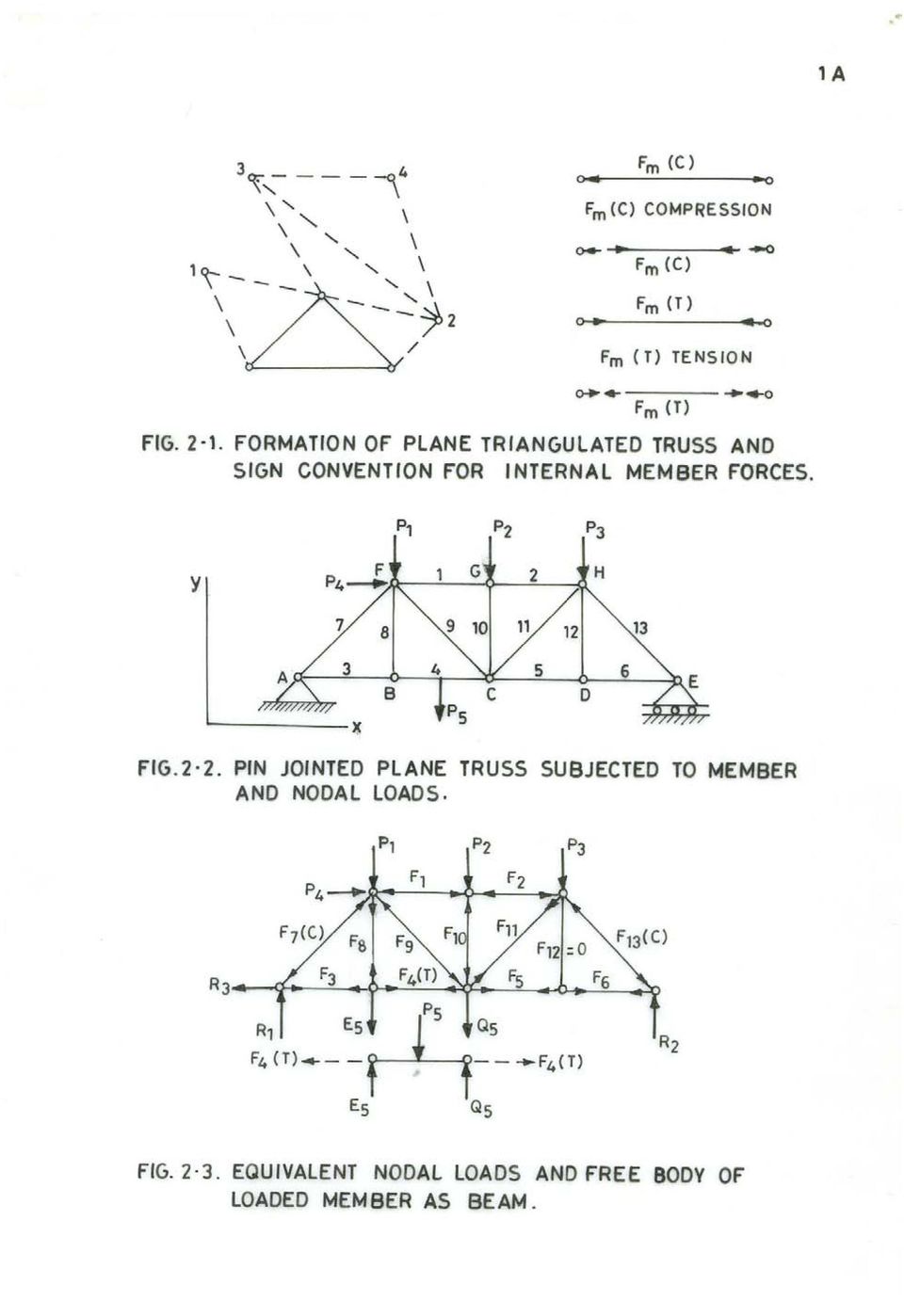
7 ECTURE NOTES ON STRUCTURA ANAYSIS BY DR. MOHAN KAANI RETIRED PROFESSOR OF STRUCTURA ENGINEERING CIVI ENGINEERING DEPARTMENT INDIAN INSTITUTE OF TECHNOOGY, MUMBAI , INDIA BASIC CONCEPTS AND CONVENTIONA METHODS OF STRUCTURA ANAYSIS 1 INTRODUCTION The structural analysis is a mathematical algorithm process by which the response of a structure to specified loads and actions is determined. This response is measured by determining the internal forces or stress resultants and displacements or deformations throughout the structure. The structural analysis is based on engineering mechanics, mechanics of solids, laboratory research, model and prototype testing, experience and engineering judgment. The basic methods of structural analysis are flexibility and stiffness methods. The flexibility method is also called force method and compatibility method. The stiffness method is also called displacement method and equilibrium method. These methods are applicable to all type of structures; however, here only skeletal systems or framed structures will be discussed. The examples of such structures are beams, arches, cables, plane trusses, space trusses, plane frames, plane grids and space frames. The skeletal structure is one whose members can be represented by lines possessing certain rigidity properties. These one dimensional members are also called bar members because their cross sectional dimensions are small in comparison to their lengths. The skeletal structures may be determinate or indeterminate. CASSIFICATIONS OF SKEETA OR FRAMED STRUCTURES They are classified as under. 1) Direct force structures such as pin jointed plane frames and ball jointed space frames which are loaded and supported at the nodes. Only one internal force or stress resultant that is axial force may arise. oads can be applied directly on the members also but they are replaced by equivalent nodal loads. In the loaded members additional internal forces such as bending moments, axial forces and shears are produced. The plane truss is formed by taking basic triangle comprising of three members and three pin joints and then adding two members and a pin node as shown in Figure.1. Sign

8
9

10

11
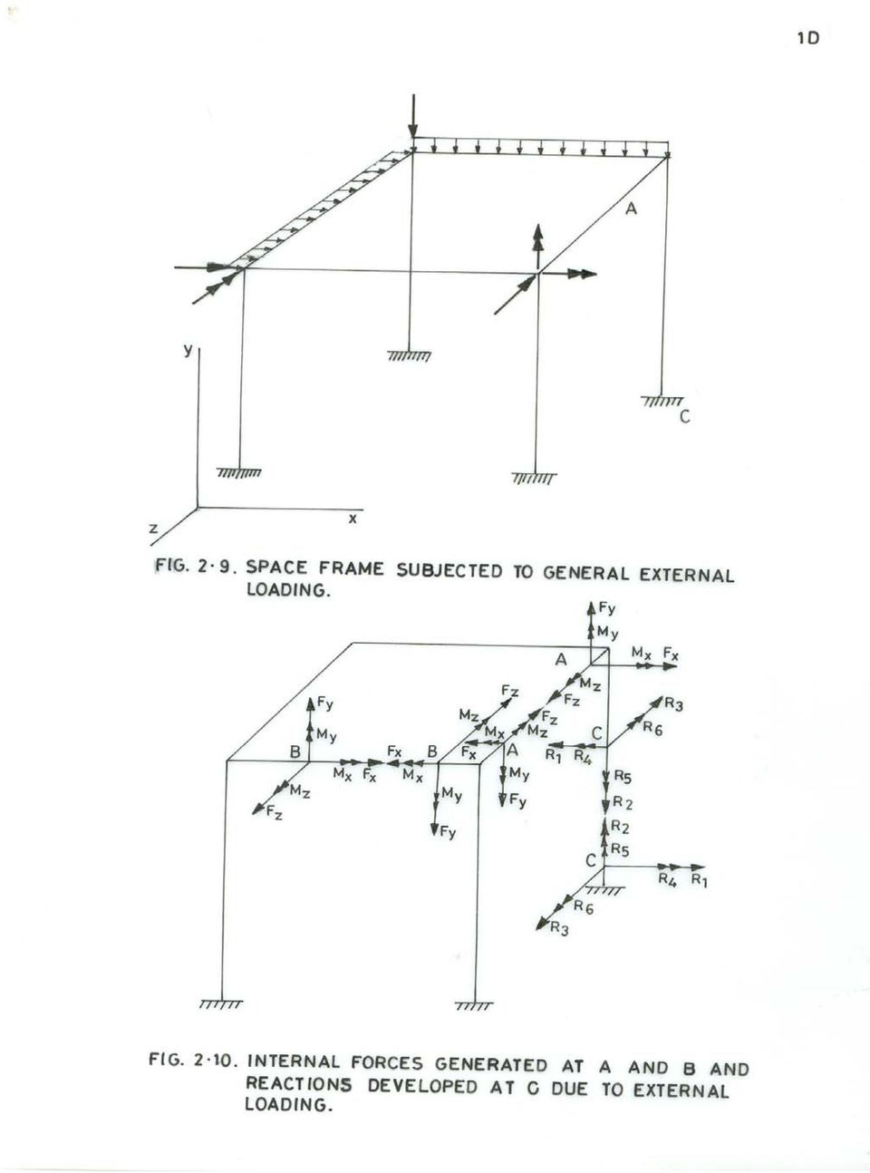
12 Convention for internal axial force is also shown. In Fig.., a plane triangulated truss with joint and member loading is shown. The replacement of member loading by joint loading is shown in Fig..3. Internal forces developed in members are also shown. The space truss is formed by taking basic prism comprising of six members and four ball joints and then adding three members and a node as shown in Fig..4. ) Plane frames in which all the members and applied forces lie in same plane as shown in Fig..5. The joints between members are generally rigid. The stress resultants are axial force, bending moment and corresponding shear force as shown in Fig..6. 3) Plane frames in which all the members lay in the same plane and all the applied loads act normal to the plane of frame as shown in Fig..7. The internal stress resultants at a point of the structure are bending moment, corresponding shear force and torsion moment as shown in Fig..8. 4) Space frames where no limitations are imposed on the geometry or loading in which maximum of six stress resultants may occur at any point of structure namely three mutually perpendicular moments of which two are bending moments and one torsion moment and three mutually perpendicular forces of which two are shear forces and one axial force as shown in figures.9 and INTERNA OADS DEVEOPED IN STRUCTURA MEMBERS External forces including moments acting on a structure produce at any section along a structural member certain internal forces including moments which are called stress resultants because they are due to internal stresses developed in the material of member. The maximum number of stress resultants that can occur at any section is six, the three Orthogonal moments and three orthogonal forces. These may also be described as the axial force F1 acting along x axis of member, two bending moments F 5 and F 6 acting about the principal y and z axes respectively of the cross section of the member, two corresponding shear forces F 3 and F acting along the principal z and y axes respectively and lastly the torsion moment F 4 acting about x axis of member. The stress resultants at any point of centroidal axis of member are shown in Fig. 3.1 and can be represented as follows. --
 Plane frames in which all the members and applied forces lie in same plane as shown in Fig..5. The joints between members are generally rigid.")
13
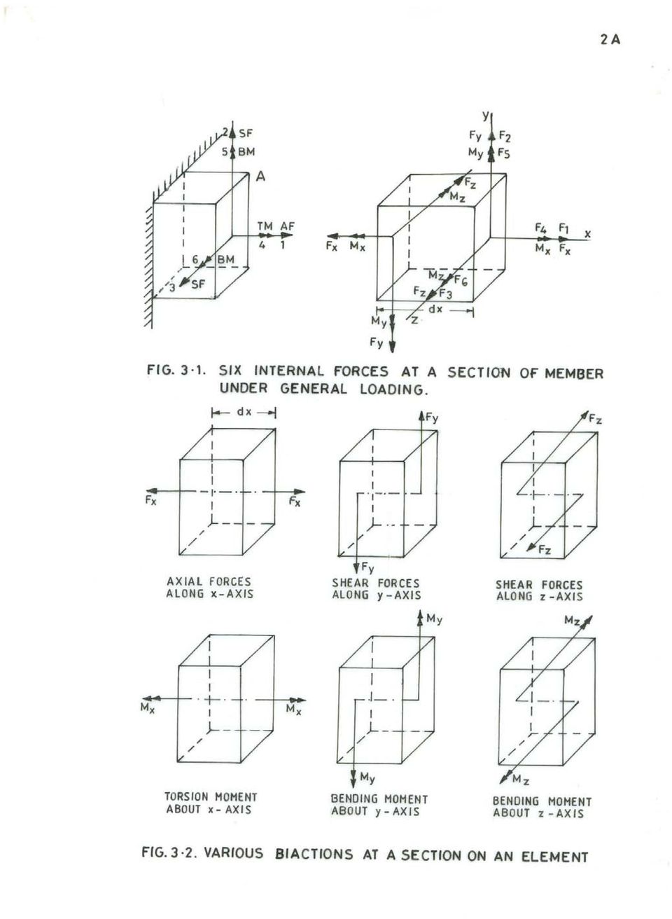
14 -3- {} F F F F = F F F OR Fx Fy Fz M M M x y z Numbering system is convenient for matrix notation and use of electronic computer. Each of these actions consists essentially of a pair of opposed actions which causes deformation of an elemental length of a member. The pair of torsion moments cause twist of the element, pair of bending moments cause bending of the element in corresponding plane, the pair of axial loads cause axial deformation in longitudinal direction and the pair of shearing forces cause shearing strains in the corresponding planes. The pairs of biactions are shown in Fig.3.. Primary and secondary internal forces. In many frames some of six internal actions contribute greatly to the elastic strain energy and hence to the distortion of elements while others contribute negligible amount. The material is assumed linearly elastic obeying Hooke s law. In direct force structures axial force is primary force, shears and bending moments are secondary. Axial force structures do not have torsional resistance. The rigid jointed plane grid under normal loading has bending moments and torsion moments as primary actions and axial forces and shears are treated secondary. In case of plane frame subjected to in plane loading only bending moment is primary action, axial force and shear force are secondary. In curved members bending moment, torsion and thrust (axial force) are primary while shear is secondary. In these particular cases many a times secondary effects are not considered as it is unnecessary to complicate the analysis by adopting general method. 4 TYPES OF STRUCTURA OADS For the analysis of structures various loads to be considered are: dead load, live load, snow load, rain load, wind load, impact load, vibration load, water current, centrifugal force, longitudinal forces, lateral forces, buoyancy force, earth or soil pressure, hydrostatic pressure, earthquake forces, thermal forces, erection forces, straining forces etc. How to consider these loads is described in loading standards of various structures. These loads are idealized for the purpose of analysis as follows.

15 -4- Concentrated loads: They are applied over a small area and are idealized as point loads. ine loads: They are distributed along narrow strip of structure such as the wall load or the self weight of member. Neglecting width, load is considered as line load acting along axis of member. Surface loads: They are distributed over an area. oads may be static or dynamic, stationary or moving. Mathematically we have point loads and concentrated moments. We have distributed forces and moments, we have straining and temperature variation forces. 5 DETERMINATE AND INDETERMINATE STRUCTURA SYSTEMS If skeletal structure is subjected to gradually increasing loads, without distorting the initial geometry of structure, that is, causing small displacements, the structure is said to be stable. Dynamic loads and buckling or instability of structural system are not considered here. If for the stable structure it is possible to find the internal forces in all the members constituting the structure and supporting reactions at all the supports provided from statical equations of equilibrium only, the structure is said to be determinate. If it is possible to determine all the support reactions from equations of equilibrium alone the structure is said to be externally determinate else externally indeterminate. If structure is externally determinate but it is not possible to determine all internal forces then structure is said to be internally indeterminate. Therefore a structural system may be: (1) Externally indeterminate but internally determinate () Externally determinate but internally indeterminate (3) Externally and internally indeterminate (4) Externally and internally determinate These systems are shown in figures 5.1 to 5.4. A system which is externally and internally determinate is said to be determinate system. A system which is externally or internally or externally and internally indeterminate is said to be indeterminate system. et: v = Total number of unknown internal and support reactions s = Total number of independent statical equations of equilibrium.

16
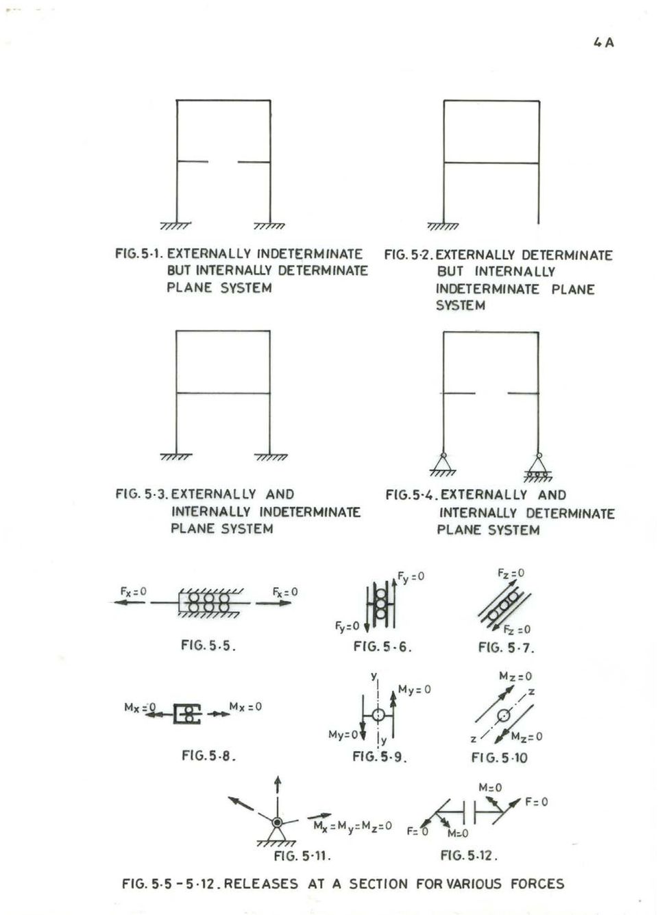
17 -5- Then if: v = s the structure is determinate v > s the structure is indeterminate v < s the structure is unstable Total indeterminacy of structure = Internal indeterminacy + External indeterminacy Equations of equilibrium Space frames arbitrarily loaded F x = 0 M x = 0 F y = 0 M y = 0 F z = 0 M z = 0 For space frames number of equations of equilibrium is 6. Forces along three orthogonal axes should vanish and moments about three orthogonal axes should vanish. Plane frames with in plane loading F x = 0 F y = 0 M z = 0 There are three equations of equilibrium. Forces in x and y directions should vanish and moment about z axis should vanish. Plane frames with normal to plane loading There are three equations of equilibrium. F y = 0, M x = 0, M z = 0 Sum of forces in y direction should be zero. Sum of moments about x and z axes be zero. Release and constraint A release is a discontinuity which renders a member incapable of transmitting a stress resultant across that section. There are six releases corresponding to the six stress resultants at a section as shown below by zero elements in the vectors. Various releases are shown in figures 5.5 to 5.1.

18 -6- Release for Axial Force (AF) F x : z y x z y M M M F F 0 Release for Shear Force (SF) F y : z y x z x M M M F 0 F Release for Shear Force (SF) F z : z y x y x M M M 0 F F Release for Torsion Moment (TM) M x : z y z y x M M 0 F F F
 M x : z y z y x M M 0 F F")
19 -7- Release for Bending Moment (BM) M y : z x z y x M 0 M F F F Release for Bending Moment (BM) M z : 0 M M F F F y x z y x The release may be represented by zero elements of forces Universal joint (Ball and socket joint) F = F F F z y x, Cut F = A release does not necessarily occur at a point, but may be continuous along whole length of member as in chain for BM. On the other hand a constraint is defined as that which prevents any relative degree of freedom between two adjacent nodes connected by a member or when a relative displacement of the nodes does not produce a stress resultant in the member. 6 INDETERMINACY OF STRUCTURA SYSTEM The indeterminacy of a structure is measured as statical ( s ) or kinematical ( k ) indeterminacy. s = P (M N + 1) r = PR r k = P (N 1) + r c
 or kinematical ( k ) indeterminacy.")
20 -8- s + k = PM c P = 6 for space frames subjected to general loading P = 3 for plane frames subjected to in plane or normal to plane loading. N = Number of nodes in structural system. M = Number of members of completely stiff structure which includes foundation as singly connected system of members. In completely stiff structure there is no release present. In singly connected system of rigid foundation members there is only one route between any two points in which tracks are not retraced. The system is considered comprising of closed rings or loops. R = Number of loops or rings in completely stiff structure. r = Number of releases in the system. c = Number of constraints in the system. R = (M N + 1) For plane and space trusses s reduces to: s = M - (NDOF) N + P M = Number of members in completely stiff truss. P = 6 and 3 for space and plane truss respectively N = Number of nodes in truss. NDOF = Degrees of freedom at node which is for plane truss and 3 for space truss. For space truss s = M - 3 N + 6 For plane truss s = M - N + 3 Test for static indeterminacy of structural system If s > 0 Structure is statically indeterminate If s = 0 Structure is statically determinate

21 -9- and if s < 0 Structure is a mechanism. It may be noted that structure may be mechanism even if s > 0 if the releases are present in such a way so as to cause collapse as mechanism. The situation of mechanism is unacceptable. Statical Indeterminacy It is difference of the unknown forces (internal forces plus external reactions) and the equations of equilibrium. Kinematic Indeterminacy It is the number of possible relative displacements of the nodes in the directions of stress resultants. Computation of static and kinematic indeterminacies It is possible to compute mentally the static and kinematic inderminacies of structures. Consider a portal frame system shown in Fig.6.1. It is space structure with five members and three clamps at foundation. There is one internal space hinge in member BC. Foundation is replaced with two stiff members to give entire system as shown in Fig.6.. So we have completely stiff structure with seven members and forms two rings which are statically indeterminate to twelve degrees as shown in Fig.6.3. There are three releases in member BC because of ball and socket (universal) joint. Three moments are zero at this section. Therefore s = 9. There are three joints E, B and C which can move. Being space system degree of freedom per node is 6. There will be three rotations at universal joint. Therefore total dof is (3 x 6 + 3) or k = 1. Joints F, A and D can not have any displacement that is degree of freedom is zero at these nodes. Using formula: s = P (M N + 1) r k = P (N 1) + r c P = 6, M = 7, N = 6 c = 1 (Foundation members are rigid), r = 3 s = P (M N + 1) r = 6 ( ) 3 = 9 k = P (N 1) + r c = 6 (6 1) = 1
22
23
24 -10- s + k = PM c = 6 x 7 1 = 30 Static indeterminacy can also be determined by introducing releases in the system and rendering it a stable determinate system. The number of biactions corresponding to releases will represent static indeterminacy. Consider a portal frame fixed at support points as shown in Fig.6.4. The entire structure is shown in Fig.6.5 and completely stiff structure in Fig.6.6. s = P (M N + 1) r k = P (N 1) + r c P = 3, M = 4, N = 4, c = 3, r = 0 s = 3 ( ) 0 = 3 k = 3 (4 1) = 6 s + k = = 9 The structure can be made determinate by introducing in many ways three releases and thus destroying its capacity to transmit internal forces X1, X, X 3 at the locations of releases. In figure 6.7. a cut is introduced just above clamp D that is clamp is removed. It becomes tree or cantilever structure with clamp at A. At this cut member was transmitting three forces X 1, X and X 3 (Two forces and one moment). Therefore s = 3. This is external static indeterminacy. In figure 6.8. a cut is introduced at point R on member BC. We have two trees or cantilevers with clamps at A and D. We have three internal unknown forces X 1, X, and X 3. Thus s = 3. In figure 6.9. three hinges are introduced. We have determinate and stable system and there are three unknown moments X 1, X and X 3. Thus s = 3. In figure one roller cum hinge and one hinge is introduced. We have one unknown force X 1 and two unknown moments X and X 3 at these releases. Thus s = 3. The static and kinematic indeterminacies of a few structures are computed in Table 1.
25
26
27 -11- TABE 1. Examples on static and kinematic indeterminacies. Example Figure P M N R c r s k No: No: FEXIBIITY AND STIFFNESS METHODS These are the two basic methods by which an indeterminate skeletal structure is analyzed. In these methods flexibility and stiffness properties of members are employed. These methods have been developed in conventional and matrix forms. Here conventional methods are discussed. Flexibility Method The given indeterminate structure is first made statically determinate by introducing suitable number of releases. The number of releases required is equal to statical indeterminacy s. Introduction of releases results in displacement discontinuities at these releases under the externally applied loads. Pairs of unknown biactions (forces and moments) are applied at these releases in order to restore the continuity or compatibility of structure. The computation of these unknown biactions involves solution of linear simultaneous equations. The number of these equations is equal to statical indeterminacy s. After the unknown biactions are computed all the internal forces can be computed in the entire structure using equations of equilibrium and free bodies of members. The required displacements can also be computed using methods of displacement computation.
28 -1- In flexibility method since unknowns are forces at the releases the method is also called force method. Since computation of displacement is also required at releases for imposing conditions of compatibility the method is also called compatibility method. In computation of displacements use is made of flexibility properties, hence, the method is also called flexibility method. Stiffness Method The given indeterminate structure is first made kinematically determinate by introducing constraints at the nodes. The required number of constraints is equal to degrees of freedom at the nodes that is kinematic indeterminacy k. The kinematically determinate structure comprises of fixed ended members, hence, all nodal displacements are zero. These results in stress resultant discontinuities at these nodes under the action of applied loads or in other words the clamped joints are not in equilibrium. In order to restore the equilibrium of stress resultants at the nodes the nodes are imparted suitable unknown displacements. The number of simultaneous equations representing joint equilibrium of forces is equal to kinematic indeterminacy k. Solution of these equations gives unknown nodal displacements. Using stiffness properties of members the member end forces are computed and hence the internal forces throughout the structure. Since nodal displacements are unknowns, the method is also called displacement method. Since equilibrium conditions are applied at the joints the method is also called equilibrium method. Since stiffness properties of members are used the method is also called stiffness method. 8 ANAYSIS OF STATICAY DETERMINATE STRUCTURES Following are the steps for analyzing statically determinate structures. (1) Obtain the reactions at the supports of structure applying appropriate equations of equilibrium. () Separate the members at the joints as free bodies and apply equations of equilibrium to each member to obtain member end forces. (3) Cut the member at a section where internal forces are required. Apply equations of equations to any of the two segments to compute unknown forces at this section. Example 8.1 Compute reactions for the beam AB loaded as shown in figure 8.1. Also find internal forces at mid span section C.
29
30 -13- Detach the beam from supports and show unknown reactions as shown in Fig.8. The reaction R B which is perpendicular to rolling surface is replaced with its horizontal and vertical components R BX and B BY. R BX = R B Sin θ = 5 3 RB, R BY = R B Cos θ = 5 4 RB At A reaction in vertical direction is zero and other components are R AX and M AZ. Resultant of triangular load W is shown acting at 8m from A and 4m from B that is through CG of triangular loading. The free body diagram with known forces is shown in Fig.8.3. W = 1 x 50 x 1 = 300 kn The equations of equilibrium for the member are: F x = 0, F y = 0 and M z = 0 Alternatively, F x = 0, M z = 0, A F x = 0 gives : R AX = R BX B M = 0 z F y = 0 gives : R BY = 300 kn B M = 0 gives : M AZ = 4 x 300 = 100 knm z A M = 0 gives : 1 R BY = 8 x M AZ, R BY = z = 300 (check) R B = 4 5 x 300 = 375, RBX = 5 3 x 375 = 5. Now the beam is cut at mid span and left segment is considered as a free body. The free body diagram of segment AC with unknown forces is shown in Fig.8.4. Total triangular load = 1 x 6 x 5 = 75 kn. It acts at 4m from A and m from C.
31 -14- F x = 0 gives, R CX = 5 kn F y = 0 gives, R CY = 75 kn C M = 0 gives, M CZ = x = 1050 knm z Example 8. Determine the reactions for the three hinged arched frame ABC loaded as shown in Fig Show free body diagrams for members AB and BC and segments BD and DC. We have three equations of equilibrium and four unknown reactions. The structure is determinate despite four unknown reactions as the moment at hinge B is zero. The free body diagrams of members AB and BC are shown in Fig.8.6 and Fig.8.7. The equations of equilibrium of free body AB are F x = 0, R AX R BX = 0. (1) F y = 0, R AY + R BY = 40 () A M = 0, 3 R BX + 4 R BY = 40 x.5 = 100 (3) z The equations of equilibrium of free body BC are : F x = 0, R BX + R CX = 5. (4) F y = 0, - R BY + R CY = 10. (5) C M = 0, 4 R BX - 3 R BY = x x = 0 (6) z These equations are solved for the unknown forces. E qn (3) x 4, 1 R BX + 16 R BY = (7) E qn (6) x 3, 1 R BX - 9 R BY = 0... (8) E qn (7) E qn (8), 5 R BY = 400, R BY = 16
32
33
34 -15- From (), R AY = = From (7), R BX = [ x 16] = = From (8), R BX = From (1), R AX = 1 9 x 16 1 From (4), R CX = 5 1 = - 7 From (5), R CY = = 6 = 1 (check) The free body diagrams of members AB and BC with known forces are shown in Figures 8.8 and 8.9. Member BDC is shown horizontally and the forces are resolved along the axis of member (suffix H) and normal to it (suffix V) as shown in figure At B : R BH = 1 cos θ + 16 sin θ = 1 x x 5 4 = 0 R BV = 1 sin θ - 16 cos θ = 1 x x 5 3 = 0 At D : R DH = 10 sin θ - 5 cos θ = 10 x x 5 3 = 5 R DV = - 5 sin θ - 10 cos θ = - 5 x x 5 3 = - 10 At C : R CH = +7 cos θ + 6 sin θ = + 7 x x 5 4 = + 5 R CV = - 7 sin θ + 6 cos θ = - 7 x x 5 3 = 10 It can easily be verified that equations of equilibrium are satisfied in this configuration. By cutting the member just to left of D the free body diagrams of segments are shown in Fig
35 -16-9 ANAYSIS OF DETERMINATE TRUSSES The trusses are classified as determinate and indeterminate. They are also classified as simple, compound and complex trusses. We have plane and space trusses. The joints of the trusses are idealized for the purpose of analysis. In case of plane trusses the joints are assumed to be hinged or pin connected. In case of space trusses ball and socket joint is assumed which is called universal joint. If members are connected to a hinge in a plane or universal joint in space, the system is equivalent to m members rigidly connected at the node with hinges or socketed balls in (m-1) number of members at the nodes as shown in figure 9.1. In other words it can be said that the members are allowed to rotate freely at the nodes. The degree of freedom at node is for plane truss (linear displacements in x and y directions) and 3 for space truss (linear displacements in x,y and z directions). The plane truss requires supports equivalent of three reactions and determinate space truss requires supports equivalent of six reactions in such a manner that supporting system is stable and should not turn into a mechanism. For this it is essential that reactions should not be concurrent and parallel so that system will not rotate and move. As regards loads they are assumed to act on the joints or points of concurrency of members. If load is acting on member it is replaced with equivalent loads applied to joints to which it is connected. Here the member discharges two functions that is function of direct force member in truss and flexural member to transmit its load to joints. For this member the two effects are combined to obtain final internal stress resultants in this member. The truss is said to be just rigid or determinate if removal of any one member destroys its rigidity and turns it into a mechanism. It is said to be over rigid or indeterminate if removal of member does not destroy its rigidity. Relation between number of members and joints for just rigid truss. et Space truss m = Number of members and j = Number of joints Number of equivalent links or members or reactive forces to constrain the truss in space is 6 corresponding to equations of equilibrium in space ( F x = 0, F y = 0, F Z = 0, M x = 0, M y = 0, M Z = 0). For ball and socket (universal) joint the minimum number of links or force components for support or constraint of joint in space is 3 corresponding to equations of equilibrium of concurrent system of forces in space ( F x = 0, F y = 0, F Z = 0). Each member is equivalent to one link or force. Total number of links or members or forces which support j number of joints in space truss is (m + 6). Thus total number of unknown member forces and reactions is (m + 6). The equations of equilibrium corresponding to j number of joints is 3j. Therefore for determinate space truss system: (m + 6) = 3j.
36 -
37
38 -17- m = (3j 6) Minimum just rigid or stable space truss as shown in Fig.9.. is a tetrahedron for which m = 6 and j = 4. For this relation between members and joints is satisfied. m = 3 x 4 6 = 6 (ok) By adding one node and three members the truss is expanded which can be supported on support system equivalent of six links or forces neither parallel nor concurrent. We get determinate and stable system. As can be seen joints 5 and 6 are added to starting stable and just rigid tetrahedron truss. Three links at each of two joints 3 and 6 corresponding to ball and socket joint are provided. Plane truss The stable and just rigid or determinate smallest plane truss as shown in Fig.9.3. comprises of a triangle with three nodes and three members. Two members and a pin joint are added to expand the truss. Total number of non-parallel and non-concurrent links or reactive forces required to support j number of joints is 3. Total number of unknowns is number of member forces and reactions at the supports. Number of available equations is j. Therefore for determinate plane truss system: (m + 3) = j m = (j 3) Hinge support is equivalent of two reactions or links and roller support is equivalent of one reaction or link. Exceptions Just rigid or simple truss is shown in figure 9.4, m = 9, j = 6, m = (j 3) = ( x 6 3) = 9. The member no 6 is removed and connected to joints and 4. As can be seen in figure 9.5. the condition of m = (j 3) is satisfied but configuration of truss can not be completed by starting with a triangle and adding two members and a joint. The system is mechanism and it is not a truss. The stable and just rigid or determinate truss is shown in figure 9.6, m = 9, j = 6, m = j 3 = x 6 3 = 9. The relation between members and joints will also be satisfied if arched part is made horizontal as shown in Fig.9.7. The system has partial constraint at C as there is nothing to balance vertical force at pin C. The two members must deflect to support vertical load at C. In fact the rule for forming determinate simple truss is violated as joint 1 is formed by members 1 and by putting them along same line because these are the only two members at that joint.
39 -18- Compound truss Compound plane truss is formed by joining together two simple plane trusses by three nonparallel and nonconcurrent members or one hinge and the member. Compound truss shown in figure 9.8 is formed by combining two simple trusses ABC and CDE by hinge at C and member BE. It is shown supported at A and B. For purpose of analysis after determining reactions at supports the two trusses are separated and unknown forces X 1, X and X 3 are determined by applying equations of equilibrium to any one part. Thereafter each part is analyzed as simple truss. This is shown in Fig.9.9. Compound truss shown in figure 9.10 is formed by combining the two simple trusses by three nonparallel and nonconcurrent members. The truss is supported by two links corresponding to hinge support at A and one link corresponding to roller at B. By cutting these three members the two parts are separated and the unknown forces X 1, X and X 3 in these members are determined by equations of equilibrium and each part is analyzed as simple truss. This is shown in Fig In case of compound space truss six members will be required to connect two simple space trusses in stable manner so that connecting system does not turn into a mechanism. Alternatively one common universal ball and socket joint and three members will be required. The method of analysis will be same as in plane truss case. Complex truss A complex truss is one which satisfies the relation between number of members and number of joints but can not be configured by rules of forming simple truss by starting with triangle or tetrahedron and then adding two members or three members and a node respectively for plane and space truss. A complex truss is shown in figure 9.1. M = 9, j = 6, m = j 3 = x 6 3 = 9 Method of analysis of determinate trusses. There are two methods of analysis for determining axial forces in members of truss under point loads acting at joints. The forces in members are tensile or compressive. The first step in each method is to compute reactions. Now we have system of members connected at nodes and subjected to external nodal forces. The member forces can be determined by following methods. (1) Method of joints () Method of sections
40
41 -19- The method of joints is used when forces in all the members are required. A particular joint is cut out and its free body diagram is prepared by showing unknown member forces. Now by applying equations of equilibrium the forces in the members meeting at this joint are computed. Proceeding from this joint to next joint and thus applying equations of equilibrium to all joints the forces in all members are computed. In case of space truss the number of unknown member forces at a joint should not be more than three. For plane case number of unknowns should not be more than two. Equations for space ball and socket joint equilibrium: F x = 0, F y = 0, F Z = 0 Equations for xy plane pin joint equilibrium : F x = 0, F y = 0 Method of sections This method is used when internal forces in some members are required. A section is passed to cut the truss in two parts exposing unknown forces in required members. The unknowns are then determined using equations of equilibrium. In plane truss not more than 3 unknowns should be exposed and in case of space truss not more than six unknowns should be exposed. Equations of equilibrium for space truss F x = 0, F y = 0, F Z = 0 using method of sections: M x = 0, M y = 0, M Z = 0 Equations of equilibrium for xy-plane F x = 0, F y = 0, M Z = 0 truss using method of sections: Example 9.1 Determine forces in all the members of plane symmetric truss loaded symmetrically as shown in figure 9.13 for all members by method of joints and in members,4 and 5 by method of sections. F x = 0 gives, R 3 = 0 A M = 0 gives, 30 R = 1000 x x 0 = 30,000, R = 1000 kn Z F y = 0 gives, R = R 1 = = 1000 kn
42 -0- Method of joints Joint A Free body is shown in figure Force in member 1 is assumed tensile and in member 3 compressive. Actions on pin at A are shown. A F = 0 : F 1 F 3 cos 45 0 = 0, X A F = 0 : - F 3 sin = 0, F 3 = 1000 Y = 1414 kn, F 1 = 1000 x 1 = 1000 kn Since positive results are obtained the direction and nature of forces F 1 and F 3 assumed are correct. At joint C there will be three unknowns, hence, we proceed to joint B where there are only two unknowns. Joint B The free body diagram of joint B is shown in figure B B F = 0 gives, F 3 cos 45 0 F 4 = 0, F 4 = 1000 X F = 0, gives : F 6 + F 3 cos 45 0 = 0, F 6 = y 1 x = 1000 kn 1 x = kn The negative sign indicates that direction of force assumed is wrong and it would be opposite. It is desirable to reverse the direction of F 6 here it self and then proceed to joint C, else the value will have to be substituted in subsequent calculation with negative sign and there are more chances of making mistakes in calculations. The corrected free body diagram of joint B is shown in figure Joint C The free body diagram for joint C is now prepared and is shown in figure C C F = 0 gives, F 5 cos 45 0 = 0, F 5 = 0 Y F = 0 gives, F = 1000 kn X
43 -1- The results are shown in figure The arrows shown at the ends of members are forces actually acting on pin joints. The reactive forces from joints onto members will decide whether it is tension or compression in the members. The sign convention was explained in theory. Method of sections Now a section is passed cutting through members, 4 and 5 and left segment is considered as a free body as shown in Fig The unknown member forces are assumed tensile. However, if it is possible to predict correct nature, the correct direction should be assumed so as to obtain positive result. A critical observation of free body indicates that F 5 = 0 as its vertical component can not be balanced as remaining resultant nodal forces in vertical direction vanish. Now equilibrium in horizontal direction indicates that F 4 = - F. The segment is subjected to clockwise moment of 10,000 knm, hence, F and F 4 should form counter clockwise couple to balance this moment. This also indicates force F 4 should have opposite direction but same magnitude. Since arm is 10 m, F x 10 = 10,000, hence, F = 1000 kn. and F 4 = kn. By method of sections we proceed as follows: D C M = 0 gives : F x x x 0 = 0, F = 1000 kn Z M = 0 gives : - F 4 x x 10 = 0, F 4 = kn Z F y = 0 gives : - F 5 x F X = 0 gives : - F 5 x = 0, F5 = F + F 4 = 0, F 5 = 0 Method of tension coefficients for space truss Consider a member AB of space truss, arbitrarily oriented in space as shown in figure 9.0. x A, y A, z A = coordinates of end A x B, y B, z B = coordinates of end B AB = length of member AB l AB, m AB, n AB = direction cosines of member AB. θ x, θ y, θ z = angle that axis of member AB makes with x, y and z axis respectively.
44
45 -- AB = ( x x ) + ( y y ) + ( z z ) B A B A B A l AB = cos θ x, m AB = cos θ y, n AB = cos θ z A = (x B x A ) = l AB AB AM = (y B y A ) = m AB AB AN = (z B z A ) = n AB AB Tension coefficient t for a member is defined as tensile force T in the member divided by its length. t = T, tab = T AB AB = tension coefficient for member AB. Components of force T AB in member AB in x, y and z directions are obtained as follows. T AB cos θ x = T ( x ) B x A AB AB T AB con θ y = T ( y ) B y A AB AB T AB cos θ z = T ( z ) B z A AB AB = t AB (x B x A ) = t AB (y B y A ) = t AB (z B z A ) P A = External force acting at joint A of space truss shown in Fig.9.1. Q A = Resultant of known member forces at joint A P AX, P AY, P AZ = Components of force P A in x,y and z directions Q AX, Q AY, Q AZ = Components of force Q A in x,y and z directions T AB, T AC, T AD = Unknown tensile forces acting on members AB, AC and AD at joint A.
46 -3- The three equations of equilibrium for joint A are written as follows. t AB (x B x A ) + t AC (x C x A ) + t AD (x D x A ) + Q AX + P AX = 0 t AB (y B y A ) + t AC (y C y A ) + t AD (y D y A ) + Q AY + P AY = 0 t AB (z B z A ) + t AC (z C z A ) + t AD (z D z A ) + Q AZ + P AZ = 0 These equations can be written in compact form by identifying any member with far and near ends. x F, y F, z F = coordinates of far end of a member x N, y N, z N = coordinates of near end of a member t (x F x N ) + Q AX + P AX = 0 t (y F y N ) + Q AY + P AY = 0 t (z F z N ) + Q AZ + P AZ = 0 Method of tension coefficients for plane trusses Plane truss member AB in tension is shown in Fig.9.. Component of pull T AB in x-direction = T AB cos θ x = T ( x ) B x A AB Component of pull T AB in y-direction = T AB cos θ y = T ( y ) B y A AB AB AB = t AB (x B x A ) = t AB (y B y A ) Positive tension coefficient t will indicate tension Negative tension coefficient t will indicate compression AB = ( x x ) + ( y y ) B A B Compact form of equations of equilibrium at joint A is: t (x F x N ) + Q AX + P AY = 0 t (y F y N ) + Q AY + P AZ = 0 A
47 -4- Example 9. For the shear leg system shown in figure 9.3 determine the axial forces in legs and tie for vertical load of 100 kn at the apex (head). ength of each leg is 5 m and spread of legs is 4 m. The distance from foot of guy rope to center of spread is 7 m. ength of guy rope is 10 m. OC = 7 m, AB = 4 m, AC = BC = m, OH = 10 m, AH = BH = 5 m. θ = angle guy makes with y axis CH = 5 = 1 = m From triangle OCH ( OH + OC CH ) Cos θ = ( OC x OH) ( ) = ( x 7 x 10) Cos θ = θ = 3.9 0, Sin θ = OD = 10 Cos θ = m HD = 10 Sin θ = m CD = =.143 m Coordinates of nodes O, H, A and B are Node x y z O H A B 7 0
48 -5- Equations of equilibrium at H are: t HA (x A x H ) + t HB (x B x H ) + t HO (x O x H ) = 0 (1) t HA (y A y H ) + t HB (y B y H ) + t HO (y O y H ) = 0 () t HA (z A z H ) + t HB (z B z H ) + t HO (z O z H ) + P HY = 0 (3) - t HA + t HB = 0 (1) t HA.143 t HB t HO = 0 () (t HA + t HB + t HO ) 100 = 0 (3) From eqn (1): t HA = t HB From eqn (): - x.143 t HA = t HO, t HA = t HO From Eqn (3): ( ) t HO = 100, t HO = t HA = t HB = x = T HO = t HO HO = x 10 = kn C HA, C HB = thrust in shear legs HA and HB C HA = C HB = x 5 = kn 10 CABES AND ARCHES 10.1 Cables Cable is a very efficient structural form as it is almost perfectly flexible. Cable has no flexural and shear strength. It has also no resistance to thrust, hence, it carries loads by simple tension only. Cable adjusts its shape to equilibrium link polygon of loads to which it is subjected. A cable has a shape of catenary under its own weight. If a large point load W compared to its own weight is applied to the cable its shape changes to two straight segments. If W is small compared to its own weight the change in shape is insignificant as shown in figure From equilibrium point of view a small segment of horizontal length dx shown in Fig.10. should satisfy two equations of equilibrium F x = 0 and F y = 0. The cable maintains its equilibrium by changing its tension and slope that is shape. One unknown cable tension T can not satisfy two equilibrium equations, hence, one additional unknown of slope θ is required. The cables are used in suspension and cable stayed bridges, cable car systems, radio towers and guys in derricks and chimneys. By assuming the shape of cable as parabolic, analysis is greatly simplified.
49
50 General cable theorem A cable subjected to point loads W 1 to W n is suspended from supports A and B over a horizontal span. ine joining supports makes angle with horizontal. Therefore elevation difference between supports is represented by tan as shown in Fig n W = W = W 1 + W W i W n i= 1 a = ΣWia ΣW i, ΣWi b b = ΣW i M = Counter clockwise moment of vertical downward loads W 1 to W n about support B B. M = b W B R A = Vertical reaction at A = B M - H tan R B = ( W + H tan - B M ) Consider a point X on cable at horizontal coordinate x from A and vertical dip y from chord. X 1 X = x tan, XX = y, XX 1 = (x tan - y) M = Counter clockwise moment of all downward loads left of X, X Since cable is assumed to be perfectly flexible the bending moment at any point of cable is zero. Considering moment equilibrium of segment of cable on left of X the relation between H, x and y is obtained which defines general cable theorem.
51 -7- H (XX 1 ) = M- R A x X H (x tan - y) = M -( X x Hy = M - M B X B M - H tan ) x Consider a horizontal beam of span subjected to same vertical loading as cable as shown in Fig et V A be reaction at A and M X bending moment at section X at coordinate x. V A = b W = B M M X = V A x - M = X B M x - M X Thus: Hy = M X The general cable theorem therefore states that at any point on the cable subjected to vertical loads, Hy the product of horizontal component of tension in cable and the vertical dip of that point from cable chord is equal to the bending moment M X at the same horizontal coordinate in a simply supported beam of same span as cable and subjected to same vertical loading as the cable. T A, T B = Tensions in cable at the supports θ A, θ B = Slopes of cable at supports T A = H + R A, θ A = tan -1 R A H T B = H + R B, θ B = tan -1 R B H If cable is subjected to vertical downward uniformly distributed load of intensityω as shown in Fig.10.4, then: ω x Hy = M X = x - ω
52 -8- At mid span x = and y = h the dip of cable. ω Hh = 4 ω 8 = ω 8 ω H = 8h 10.3 Shape of cable Hy = M X ω ω x y = x - ω 8h 4h y = x ( x) This is the equation of cable curve with respect to cable chord. The cable thus takes the shape of parabola under the action of udl. The same equation is valid when chord is horizontal as shown in Fig ength of cable with both ends at same level S = O ds = O dy 1+ dx dx dy 4h = ( x) dx S = 1 ( - x) O 16h + This will give: 1 dx S = h 3 h 56 h
53
54 -9- For flat parabolic curves h 1 10, only two terms are retained. S = 8 h Example A flexible cable weighing 1 N/m horizontally is suspended over a span of 40 m as shown in Fig It carries a concentrated load of 300 N at point P at horizontal coordinate 10 m from left hand support. Find dip at P so that tension in cable does not exceed 1000 N. R A = ( 300 x x 40 x 0 ) 40 = 45 N R B = ( x 1) 45 = 95 N R A + R B = 340 N = Total vertical load (ok) Since R B < R A, maximum tension will occur at A. H + 45 = 1000 H = = , H = (Rounded to 970) H = 970 N Considering segment left of P, the clockwise moment at P is computed and set to zero since cable is flexible. M P = R A x 10 Hh 10 x 5 = h 50 = h = h = =.474 m Arches An arch is a curved beam circular or parabolic in form supported at its ends and is subjected to inplane loading. The internal forces developed in the arch are axial force, shear force and bending moment. Depending upon number of hinges the arches are
55 -30- classified as (1) three hinged arch () two hinged arch (3) single hinged arch and (4) fixed arch as shown in figures 10.7 to A three hinged arch is statically determinate. The remaining three are statically indeterminate to first, second and third degree respectively. Here only determinate three hinged arch will be considered. Arch under vertical point loads shown in figure is a three hinged arch subjected to vertical loads W 1 to W n. The reactions developed at the supports are shown. It may be noted that moment at the hinge at C in the arch is zero, hence, horizontal component of reaction can be computed from this condition. R A = bσw, R B = M= R A - Hh C aσw, W = W W n bσw H = h C M M = Counter clockwise moment about C of all applied vertical loads acting left of C C W = Resultant of all applied vertical loads acting downwards At any point P on the arch as shown in Fig.10.1, the internal forces F x,f y and M z can easily be computed as explained previously. From F x and F y shear force and thrust in the arch can be computed. θ = Slope of arch axis at P. V = Shear at P C = Thrust at P M = Bending moment at P M = M z V = F y cos θ - F x Sin θ C = - F y Sin θ - F x cos θ
56
57 Three hinged parabolic arch under udl The three hinged arch under udl is shown in Fig The equation of axis of arch is: 4h y = x ( x) R A = R B = ω By the condition that moment is zero at C: ω R A - Hh - = 0 4 H = h 1 ω - 8 ω + 4 = ω 8h Consider a section P having coordinates (x,y). ω ω M x = x - 8h y - ωx = ω ω x - x ω - 8h 4h x ( - x) = ω ωx ωx x ωx = 0 The bending moment in parabolic arch under vertical udl is zero Example A three hinged parabolic arch of 0 m span and 4 m central rise as shown in Fig carries a point load of 40 kn at 4 m horizontally from left support. Compute BM, SF and AF at load point. Also determine maximum positive and negative bending moments in the arch and plot the bending moment diagram.
58 -3-4h 4 x 4 y = x ( x) = 400 x (0 x) x y = 5 (0 x) 4 16 R B = x 40 = 8 kn, RA = x 40 = 3 kn 0 0 M C = 0, 4H = 3 x x 6 = 80, H = 0 kn 0 x 4 m x 4 M x = 3 x 0 (0 x) = 16 x + x 5 5 x = 4, M x = 16 x x 16 5 = 76.8 knm 4 m x 0 m x 4 M x = 3 x 0 (0 x) 40 (x 4) = x + x 5 5 x = 4, M x = 76.8 knm (check) x = 10, M x = = 0 x = 15, M x = x x 5 = - 0 knm x = 0, M x = 0 (ok) The bending moment diagram is parabolic as shown in Fig INFUENCE INES FOR DETERMINATE STRUCTURES An influence line is a graph or curve showing the variation of any function such as reaction, bending moment, shearing farce, axial force, torsion moment, stress or stress resultant and displacement at a given section or point of structure, as a unit load acting parallel to a given direction crosses the structure. The influence line gives the value of the function at only one point or section of the structure and at no other point. A separate influence line is to be drawn for the function at any other point.
Structural Axial, Shear and Bending Moments
 Structural Axial, Shear and Bending Moments Positive Internal Forces Acting Recall from mechanics of materials that the internal forces P (generic axial), V (shear) and M (moment) represent resultants
Statics of Structural Supports
 Statics of Structural Supports TYPES OF FORCES External Forces actions of other bodies on the structure under consideration. Internal Forces forces and couples exerted on a member or portion of the structure
Problem 1: Computation of Reactions. Problem 2: Computation of Reactions. Problem 3: Computation of Reactions
 Problem 1: Computation of Reactions Problem 2: Computation of Reactions Problem 3: Computation of Reactions Problem 4: Computation of forces and moments Problem 5: Bending Moment and Shear force Problem
Deflections. Question: What are Structural Deflections?
 Question: What are Structural Deflections? Answer: The deformations or movements of a structure and its components, such as beams and trusses, from their original positions. It is as important for the
Module 2. Analysis of Statically Indeterminate Structures by the Matrix Force Method. Version 2 CE IIT, Kharagpur
 Module Analysis of Statically Indeterminate Structures by the Matrix Force Method esson 11 The Force Method of Analysis: Frames Instructional Objectives After reading this chapter the student will be able
Structural Analysis - II Prof. P. Banerjee Department of Civil Engineering Indian Institute of Technology, Bombay. Lecture - 02
 Structural Analysis - II Prof. P. Banerjee Department of Civil Engineering Indian Institute of Technology, Bombay Lecture - 02 Good morning. Today is the second lecture in the series of lectures on structural
The elements used in commercial codes can be classified in two basic categories:
 CHAPTER 3 Truss Element 3.1 Introduction The single most important concept in understanding FEA, is the basic understanding of various finite elements that we employ in an analysis. Elements are used for
Statically Indeterminate Structure. : More unknowns than equations: Statically Indeterminate
 Statically Indeterminate Structure : More unknowns than equations: Statically Indeterminate 1 Plane Truss :: Determinacy No. of unknown reactions = 3 No. of equilibrium equations = 3 : Statically Determinate
8.2 Elastic Strain Energy
 Section 8. 8. Elastic Strain Energy The strain energy stored in an elastic material upon deformation is calculated below for a number of different geometries and loading conditions. These expressions for
New approaches in Eurocode 3 efficient global structural design
 New approaches in Eurocode 3 efficient global structural design Part 1: 3D model based analysis using general beam-column FEM Ferenc Papp* and József Szalai ** * Associate Professor, Department of Structural
4.2 Free Body Diagrams
 CE297-FA09-Ch4 Page 1 Friday, September 18, 2009 12:11 AM Chapter 4: Equilibrium of Rigid Bodies A (rigid) body is said to in equilibrium if the vector sum of ALL forces and all their moments taken about
DESIGN OF SLABS. 3) Based on support or boundary condition: Simply supported, Cantilever slab,
 Based on support or boundary condition: Simply supported, Cantilever slab,") DESIGN OF SLABS Dr. G. P. Chandradhara Professor of Civil Engineering S. J. College of Engineering Mysore 1. GENERAL A slab is a flat two dimensional planar structural element having thickness small compared
DESIGN OF SLABS Dr. G. P. Chandradhara Professor of Civil Engineering S. J. College of Engineering Mysore 1. GENERAL A slab is a flat two dimensional planar structural element having thickness small compared
Optimum proportions for the design of suspension bridge
 Journal of Civil Engineering (IEB), 34 (1) (26) 1-14 Optimum proportions for the design of suspension bridge Tanvir Manzur and Alamgir Habib Department of Civil Engineering Bangladesh University of Engineering
MECHANICS OF SOLIDS - BEAMS TUTORIAL 2 SHEAR FORCE AND BENDING MOMENTS IN BEAMS
 MECHANICS OF SOLIDS - BEAMS TUTORIAL 2 SHEAR FORCE AND BENDING MOMENTS IN BEAMS This is the second tutorial on bending of beams. You should judge your progress by completing the self assessment exercises.
Mechanics of Materials. Chapter 4 Shear and Moment In Beams
 Mechanics of Materials Chapter 4 Shear and Moment In Beams 4.1 Introduction The term beam refers to a slender bar that carries transverse loading; that is, the applied force are perpendicular to the bar.
SOLID MECHANICS TUTORIAL MECHANISMS KINEMATICS - VELOCITY AND ACCELERATION DIAGRAMS
 SOLID MECHANICS TUTORIAL MECHANISMS KINEMATICS - VELOCITY AND ACCELERATION DIAGRAMS This work covers elements of the syllabus for the Engineering Council exams C105 Mechanical and Structural Engineering
Section 16: Neutral Axis and Parallel Axis Theorem 16-1
 Section 16: Neutral Axis and Parallel Axis Theorem 16-1 Geometry of deformation We will consider the deformation of an ideal, isotropic prismatic beam the cross section is symmetric about y-axis All parts
Chapter 11 Equilibrium
 11.1 The First Condition of Equilibrium The first condition of equilibrium deals with the forces that cause possible translations of a body. The simplest way to define the translational equilibrium of
Analysis of Stresses and Strains
 Chapter 7 Analysis of Stresses and Strains 7.1 Introduction axial load = P / A torsional load in circular shaft = T / I p bending moment and shear force in beam = M y / I = V Q / I b in this chapter, we
ENGINEERING SCIENCE H1 OUTCOME 1 - TUTORIAL 3 BENDING MOMENTS EDEXCEL HNC/D ENGINEERING SCIENCE LEVEL 4 H1 FORMERLY UNIT 21718P
 ENGINEERING SCIENCE H1 OUTCOME 1 - TUTORIAL 3 BENDING MOMENTS EDEXCEL HNC/D ENGINEERING SCIENCE LEVEL 4 H1 FORMERLY UNIT 21718P This material is duplicated in the Mechanical Principles module H2 and those
MECHANICS OF SOLIDS - BEAMS TUTORIAL 1 STRESSES IN BEAMS DUE TO BENDING. On completion of this tutorial you should be able to do the following.
 MECHANICS OF SOLIDS - BEAMS TUTOIAL 1 STESSES IN BEAMS DUE TO BENDING This is the first tutorial on bending of beams designed for anyone wishing to study it at a fairly advanced level. You should judge
Bedford, Fowler: Statics. Chapter 4: System of Forces and Moments, Examples via TK Solver
 System of Forces and Moments Introduction The moment vector of a force vector,, with respect to a point has a magnitude equal to the product of the force magnitude, F, and the perpendicular distance from
Solving Simultaneous Equations and Matrices
 Solving Simultaneous Equations and Matrices The following represents a systematic investigation for the steps used to solve two simultaneous linear equations in two unknowns. The motivation for considering
THREE DIMENSIONAL GEOMETRY
 Chapter 8 THREE DIMENSIONAL GEOMETRY 8.1 Introduction In this chapter we present a vector algebra approach to three dimensional geometry. The aim is to present standard properties of lines and planes,
PLANE TRUSSES. Definitions
 Definitions PLANE TRUSSES A truss is one of the major types of engineering structures which provides a practical and economical solution for many engineering constructions, especially in the design of
EDEXCEL NATIONAL CERTIFICATE/DIPLOMA MECHANICAL PRINCIPLES AND APPLICATIONS NQF LEVEL 3 OUTCOME 1 - LOADING SYSTEMS
 EDEXCEL NATIONAL CERTIFICATE/DIPLOMA MECHANICAL PRINCIPLES AND APPLICATIONS NQF LEVEL 3 OUTCOME 1 - LOADING SYSTEMS TUTORIAL 1 NON-CONCURRENT COPLANAR FORCE SYSTEMS 1. Be able to determine the effects
Copyright 2011 Casa Software Ltd. www.casaxps.com. Centre of Mass
 Centre of Mass A central theme in mathematical modelling is that of reducing complex problems to simpler, and hopefully, equivalent problems for which mathematical analysis is possible. The concept of
Statics problem solving strategies, hints and tricks
 Statics problem solving strategies, hints and tricks Contents 1 Solving a problem in 7 steps 3 1.1 To read.............................................. 3 1.2 To draw..............................................
Approximate Analysis of Statically Indeterminate Structures
 Approximate Analysis of Statically Indeterminate Structures Every successful structure must be capable of reaching stable equilibrium under its applied loads, regardless of structural behavior. Exact analysis
CE 201 (STATICS) DR. SHAMSHAD AHMAD CIVIL ENGINEERING ENGINEERING MECHANICS-STATICS
 DR. SHAMSHAD AHMAD CIVIL ENGINEERING ENGINEERING MECHANICS-STATICS") COURSE: CE 201 (STATICS) LECTURE NO.: 28 to 30 FACULTY: DR. SHAMSHAD AHMAD DEPARTMENT: CIVIL ENGINEERING UNIVERSITY: KING FAHD UNIVERSITY OF PETROLEUM & MINERALS, DHAHRAN, SAUDI ARABIA TEXT BOOK: ENGINEERING
COURSE: CE 201 (STATICS) LECTURE NO.: 28 to 30 FACULTY: DR. SHAMSHAD AHMAD DEPARTMENT: CIVIL ENGINEERING UNIVERSITY: KING FAHD UNIVERSITY OF PETROLEUM & MINERALS, DHAHRAN, SAUDI ARABIA TEXT BOOK: ENGINEERING
P4 Stress and Strain Dr. A.B. Zavatsky MT07 Lecture 3 Statically Indeterminate Structures
 4 Stress and Strain Dr... Zavatsky MT07 ecture 3 Statically Indeterminate Structures Statically determinate structures. Statically indeterminate structures (equations of equilibrium, compatibility, and
Advanced Structural Analysis. Prof. Devdas Menon. Department of Civil Engineering. Indian Institute of Technology, Madras. Module - 5.3.
 Advanced Structural Analysis Prof. Devdas Menon Department of Civil Engineering Indian Institute of Technology, Madras Module - 5.3 Lecture - 29 Matrix Analysis of Beams and Grids Good morning. This is
2. Axial Force, Shear Force, Torque and Bending Moment Diagrams
 2. Axial Force, Shear Force, Torque and Bending Moment Diagrams In this section, we learn how to summarize the internal actions (shear force and bending moment) that occur throughout an axial member, shaft,
METHODS FOR ACHIEVEMENT UNIFORM STRESSES DISTRIBUTION UNDER THE FOUNDATION
 International Journal of Civil Engineering and Technology (IJCIET) Volume 7, Issue 2, March-April 2016, pp. 45-66, Article ID: IJCIET_07_02_004 Available online at http://www.iaeme.com/ijciet/issues.asp?jtype=ijciet&vtype=7&itype=2
Chapter 1: Statics. A) Newtonian Mechanics B) Relativistic Mechanics
 Newtonian Mechanics B) Relativistic Mechanics") Chapter 1: Statics 1. The subject of mechanics deals with what happens to a body when is / are applied to it. A) magnetic field B) heat C ) forces D) neutrons E) lasers 2. still remains the basis of most
Chapter 1: Statics 1. The subject of mechanics deals with what happens to a body when is / are applied to it. A) magnetic field B) heat C ) forces D) neutrons E) lasers 2. still remains the basis of most
Design of Steel Structures Prof. S.R.Satish Kumar and Prof. A.R.Santha Kumar. Fig. 7.21 some of the trusses that are used in steel bridges
 7.7 Truss bridges Fig. 7.21 some of the trusses that are used in steel bridges Truss Girders, lattice girders or open web girders are efficient and economical structural systems, since the members experience
Recitation #5. Understanding Shear Force and Bending Moment Diagrams
 Recitation #5 Understanding Shear Force and Bending Moment Diagrams Shear force and bending moment are examples of interanl forces that are induced in a structure when loads are applied to that structure.
Finite Element Formulation for Beams - Handout 2 -
 Finite Element Formulation for Beams - Handout 2 - Dr Fehmi Cirak (fc286@) Completed Version Review of Euler-Bernoulli Beam Physical beam model midline Beam domain in three-dimensions Midline, also called
INTRODUCTION TO BEAMS
 CHAPTER Structural Steel Design LRFD Method INTRODUCTION TO BEAMS Third Edition A. J. Clark School of Engineering Department of Civil and Environmental Engineering Part II Structural Steel Design and Analysis
EFFECTS ON NUMBER OF CABLES FOR MODAL ANALYSIS OF CABLE-STAYED BRIDGES
 EFFECTS ON NUMBER OF CABLES FOR MODAL ANALYSIS OF CABLE-STAYED BRIDGES Yang-Cheng Wang Associate Professor & Chairman Department of Civil Engineering Chinese Military Academy Feng-Shan 83000,Taiwan Republic
THEORETICAL MECHANICS
 PROF. DR. ING. VASILE SZOLGA THEORETICAL MECHANICS LECTURE NOTES AND SAMPLE PROBLEMS PART ONE STATICS OF THE PARTICLE, OF THE RIGID BODY AND OF THE SYSTEMS OF BODIES KINEMATICS OF THE PARTICLE 2010 0 Contents
When the fluid velocity is zero, called the hydrostatic condition, the pressure variation is due only to the weight of the fluid.
 Fluid Statics When the fluid velocity is zero, called the hydrostatic condition, the pressure variation is due only to the weight of the fluid. Consider a small wedge of fluid at rest of size Δx, Δz, Δs
Technical Notes 3B - Brick Masonry Section Properties May 1993
 Technical Notes 3B - Brick Masonry Section Properties May 1993 Abstract: This Technical Notes is a design aid for the Building Code Requirements for Masonry Structures (ACI 530/ASCE 5/TMS 402-92) and Specifications
Nonlinear analysis and form-finding in GSA Training Course
 Nonlinear analysis and form-finding in GSA Training Course Non-linear analysis and form-finding in GSA 1 of 47 Oasys Ltd Non-linear analysis and form-finding in GSA 2 of 47 Using the GSA GsRelax Solver
Section 1.1. Introduction to R n
 The Calculus of Functions of Several Variables Section. Introduction to R n Calculus is the study of functional relationships and how related quantities change with each other. In your first exposure to
Shear Forces and Bending Moments
 Chapter 4 Shear Forces and Bending Moments 4.1 Introduction Consider a beam subjected to transverse loads as shown in figure, the deflections occur in the plane same as the loading plane, is called the
Equations Involving Lines and Planes Standard equations for lines in space
 Equations Involving Lines and Planes In this section we will collect various important formulas regarding equations of lines and planes in three dimensional space Reminder regarding notation: any quantity
Stresses in Beam (Basic Topics)
") Chapter 5 Stresses in Beam (Basic Topics) 5.1 Introduction Beam : loads acting transversely to the longitudinal axis the loads create shear forces and bending moments, stresses and strains due to V and
Chapter 5 Stresses in Beam (Basic Topics) 5.1 Introduction Beam : loads acting transversely to the longitudinal axis the loads create shear forces and bending moments, stresses and strains due to V and
Course in. Nonlinear FEM
 Course in Introduction Outline Lecture 1 Introduction Lecture 2 Geometric nonlinearity Lecture 3 Material nonlinearity Lecture 4 Material nonlinearity continued Lecture 5 Geometric nonlinearity revisited
STRESS AND DEFORMATION ANALYSIS OF LINEAR ELASTIC BARS IN TENSION
 Chapter 11 STRESS AND DEFORMATION ANALYSIS OF LINEAR ELASTIC BARS IN TENSION Figure 11.1: In Chapter10, the equilibrium, kinematic and constitutive equations for a general three-dimensional solid deformable
SECTION 5 ANALYSIS OF CONTINUOUS SPANS DEVELOPED BY THE PTI EDC-130 EDUCATION COMMITTEE LEAD AUTHOR: BRYAN ALLRED
 SECTION 5 ANALYSIS OF CONTINUOUS SPANS DEVELOPED BY THE PTI EDC-130 EDUCATION COMMITTEE LEAD AUTHOR: BRYAN ALLRED NOTE: MOMENT DIAGRAM CONVENTION In PT design, it is preferable to draw moment diagrams
11.1. Objectives. Component Form of a Vector. Component Form of a Vector. Component Form of a Vector. Vectors and the Geometry of Space
 11 Vectors and the Geometry of Space 11.1 Vectors in the Plane Copyright Cengage Learning. All rights reserved. Copyright Cengage Learning. All rights reserved. 2 Objectives! Write the component form of
The Basics of FEA Procedure
 CHAPTER 2 The Basics of FEA Procedure 2.1 Introduction This chapter discusses the spring element, especially for the purpose of introducing various concepts involved in use of the FEA technique. A spring
Adding vectors We can do arithmetic with vectors. We ll start with vector addition and related operations. Suppose you have two vectors
 1 Chapter 13. VECTORS IN THREE DIMENSIONAL SPACE Let s begin with some names and notation for things: R is the set (collection) of real numbers. We write x R to mean that x is a real number. A real number
Mechanics lecture 7 Moment of a force, torque, equilibrium of a body
 G.1 EE1.el3 (EEE1023): Electronics III Mechanics lecture 7 Moment of a force, torque, equilibrium of a body Dr Philip Jackson http://www.ee.surrey.ac.uk/teaching/courses/ee1.el3/ G.2 Moments, torque and
Solutions to old Exam 1 problems
 Solutions to old Exam 1 problems Hi students! I am putting this old version of my review for the first midterm review, place and time to be announced. Check for updates on the web site as to which sections
bi directional loading). Prototype ten story
. Prototype ten story") NEESR SG: Behavior, Analysis and Design of Complex Wall Systems The laboratory testing presented here was conducted as part of a larger effort that employed laboratory testing and numerical simulation
NEESR SG: Behavior, Analysis and Design of Complex Wall Systems The laboratory testing presented here was conducted as part of a larger effort that employed laboratory testing and numerical simulation
Two vectors are equal if they have the same length and direction. They do not
 Vectors define vectors Some physical quantities, such as temperature, length, and mass, can be specified by a single number called a scalar. Other physical quantities, such as force and velocity, must
Finite Element Formulation for Plates - Handout 3 -
 Finite Element Formulation for Plates - Handout 3 - Dr Fehmi Cirak (fc286@) Completed Version Definitions A plate is a three dimensional solid body with one of the plate dimensions much smaller than the
CHAPTER 3. INTRODUCTION TO MATRIX METHODS FOR STRUCTURAL ANALYSIS
 1 CHAPTER 3. INTRODUCTION TO MATRIX METHODS FOR STRUCTURAL ANALYSIS Written by: Sophia Hassiotis, January, 2003 Last revision: February, 2015 Modern methods of structural analysis overcome some of the
State of Stress at Point
 State of Stress at Point Einstein Notation The basic idea of Einstein notation is that a covector and a vector can form a scalar: This is typically written as an explicit sum: According to this convention,
Solid Mechanics. Stress. What you ll learn: Motivation
 Solid Mechanics Stress What you ll learn: What is stress? Why stress is important? What are normal and shear stresses? What is strain? Hooke s law (relationship between stress and strain) Stress strain
DISTRIBUTION OF LOADSON PILE GROUPS
 C H A P T E R 7 DISTRIBUTION OF LOADSON PILE GROUPS Section I. DESIGN LOADS 7-1. Basic design. The load carried by an individual pile or group of piles in a foundation depends upon the structure concerned
ANALYTICAL METHODS FOR ENGINEERS
 UNIT 1: Unit code: QCF Level: 4 Credit value: 15 ANALYTICAL METHODS FOR ENGINEERS A/601/1401 OUTCOME - TRIGONOMETRIC METHODS TUTORIAL 1 SINUSOIDAL FUNCTION Be able to analyse and model engineering situations
How To Write An Analysis System For Bridge Test
 Study of Analysis System for Bridge Test Chen Ke, Lu Jian-Ming, Research Institute of Highway, 100088, Beijing, China (chenkezi@163.com, lujianming@263.net) Summary Analysis System for Bridge Test (Chinese
ENGINEERING MECHANICS STATIC
 EX 16 Using the method of joints, determine the force in each member of the truss shown. State whether each member in tension or in compression. Sol Free-body diagram of the pin at B X = 0 500- BC sin
MECHANICS OF SOLIDS - BEAMS TUTORIAL TUTORIAL 4 - COMPLEMENTARY SHEAR STRESS
 MECHANICS OF SOLIDS - BEAMS TUTORIAL TUTORIAL 4 - COMPLEMENTARY SHEAR STRESS This the fourth and final tutorial on bending of beams. You should judge our progress b completing the self assessment exercises.
Vector Notation: AB represents the vector from point A to point B on a graph. The vector can be computed by B A.
 1 Linear Transformations Prepared by: Robin Michelle King A transformation of an object is a change in position or dimension (or both) of the object. The resulting object after the transformation is called
Design Analysis and Review of Stresses at a Point
 Design Analysis and Review of Stresses at a Point Need for Design Analysis: To verify the design for safety of the structure and the users. To understand the results obtained in FEA, it is necessary to
IMPROVING THE STRUT AND TIE METHOD BY INCLUDING THE CONCRETE SOFTENING EFFECT
 International Journal of Civil Engineering and Technology (IJCIET) Volume 7, Issue 2, March-April 2016, pp. 117 127, Article ID: IJCIET_07_02_009 Available online at http://www.iaeme.com/ijciet/issues.asp?jtype=ijciet&vtype=7&itype=2
EDEXCEL NATIONAL CERTIFICATE/DIPLOMA MECHANICAL PRINCIPLES OUTCOME 2 ENGINEERING COMPONENTS TUTORIAL 1 STRUCTURAL MEMBERS
 ENGINEERING COMPONENTS EDEXCEL NATIONAL CERTIFICATE/DIPLOMA MECHANICAL PRINCIPLES OUTCOME ENGINEERING COMPONENTS TUTORIAL 1 STRUCTURAL MEMBERS Structural members: struts and ties; direct stress and strain,
Analysis of Statically Determinate Trusses
 Analysis of Statically Determinate Trusses THEORY OF STRUCTURES Asst. Prof. Dr. Cenk Üstündağ Common Types of Trusses A truss is one of the major types of engineering structures which provides a practical
WORK DONE BY A CONSTANT FORCE
 WORK DONE BY A CONSTANT FORCE The definition of work, W, when a constant force (F) is in the direction of displacement (d) is W = Fd SI unit is the Newton-meter (Nm) = Joule, J If you exert a force of
Lecture 4. Case Study of 16 th C Church in Old Goa
 Lecture 4 Case Study of 16 th C Church in Old Goa Case Study: 16 th C. Church in Goa,, India 16th C. Church in Goa,, India 16th C. Church in Goa,, India 13.4 m 15.2 m 12.5 m 2.7 m 9.0 m 2.7 m Unit weight
Objectives. Experimentally determine the yield strength, tensile strength, and modules of elasticity and ductility of given materials.
 Lab 3 Tension Test Objectives Concepts Background Experimental Procedure Report Requirements Discussion Objectives Experimentally determine the yield strength, tensile strength, and modules of elasticity
13.4 THE CROSS PRODUCT
 710 Chapter Thirteen A FUNDAMENTAL TOOL: VECTORS 62. Use the following steps and the results of Problems 59 60 to show (without trigonometry) that the geometric and algebraic definitions of the dot product
PHY121 #8 Midterm I 3.06.2013
 PHY11 #8 Midterm I 3.06.013 AP Physics- Newton s Laws AP Exam Multiple Choice Questions #1 #4 1. When the frictionless system shown above is accelerated by an applied force of magnitude F, the tension
Midterm Solutions. mvr = ω f (I wheel + I bullet ) = ω f 2 MR2 + mr 2 ) ω f = v R. 1 + M 2m
 = ω f 2 MR2 + mr 2 ) ω f = v R. 1 + M 2m") Midterm Solutions I) A bullet of mass m moving at horizontal velocity v strikes and sticks to the rim of a wheel a solid disc) of mass M, radius R, anchored at its center but free to rotate i) Which of
Midterm Solutions I) A bullet of mass m moving at horizontal velocity v strikes and sticks to the rim of a wheel a solid disc) of mass M, radius R, anchored at its center but free to rotate i) Which of
Rotation: Moment of Inertia and Torque
 Rotation: Moment of Inertia and Torque Every time we push a door open or tighten a bolt using a wrench, we apply a force that results in a rotational motion about a fixed axis. Through experience we learn
Finite Element Simulation of Simple Bending Problem and Code Development in C++
 EUROPEAN ACADEMIC RESEARCH, VOL. I, ISSUE 6/ SEPEMBER 013 ISSN 86-48, www.euacademic.org IMPACT FACTOR: 0.485 (GIF) Finite Element Simulation of Simple Bending Problem and Code Development in C++ ABDUL
Tutorial for Assignment #2 Gantry Crane Analysis By ANSYS (Mechanical APDL) V.13.0
 V.13.0") Tutorial for Assignment #2 Gantry Crane Analysis By ANSYS (Mechanical APDL) V.13.0 1 Problem Description Design a gantry crane meeting the geometry presented in Figure 1 on page #325 of the course textbook
Tutorial for Assignment #2 Gantry Crane Analysis By ANSYS (Mechanical APDL) V.13.0 1 Problem Description Design a gantry crane meeting the geometry presented in Figure 1 on page #325 of the course textbook
4B-2. 2. The stiffness of the floor and roof diaphragms. 3. The relative flexural and shear stiffness of the shear walls and of connections.
 Shear Walls Buildings that use shear walls as the lateral force-resisting system can be designed to provide a safe, serviceable, and economical solution for wind and earthquake resistance. Shear walls
In-situ Load Testing to Evaluate New Repair Techniques
 In-situ Load Testing to Evaluate New Repair Techniques W.J. Gold 1 and A. Nanni 2 1 Assistant Research Engineer, Univ. of Missouri Rolla, Dept. of Civil Engineering 2 V&M Jones Professor, Univ. of Missouri
REINFORCED CONCRETE. Reinforced Concrete Design. A Fundamental Approach - Fifth Edition. Walls are generally used to provide lateral support for:
 HANDOUT REINFORCED CONCRETE Reinforced Concrete Design A Fundamental Approach - Fifth Edition RETAINING WALLS Fifth Edition A. J. Clark School of Engineering Department of Civil and Environmental Engineering
SEISMIC DESIGN. Various building codes consider the following categories for the analysis and design for earthquake loading:
 SEISMIC DESIGN Various building codes consider the following categories for the analysis and design for earthquake loading: 1. Seismic Performance Category (SPC), varies from A to E, depending on how the
Lecture 6. Weight. Tension. Normal Force. Static Friction. Cutnell+Johnson: 4.8-4.12, second half of section 4.7
 Lecture 6 Weight Tension Normal Force Static Friction Cutnell+Johnson: 4.8-4.12, second half of section 4.7 In this lecture, I m going to discuss four different kinds of forces: weight, tension, the normal
Chapter 4. Forces and Newton s Laws of Motion. continued
 Chapter 4 Forces and Newton s Laws of Motion continued 4.9 Static and Kinetic Frictional Forces When an object is in contact with a surface forces can act on the objects. The component of this force acting
FOOTING DESIGN EXAMPLE
 County: Any Design: BRG Date: 10/007 Hwy: Any Ck Dsn: BRG Date: 10/007 FOOTING DESIGN EXAMPLE Design: Based on AASHTO LRFD 007 Specifications, TxDOT LRFD Bridge Design Manual, and TxDOT Project 0-4371
COMPLEX STRESS TUTORIAL 3 COMPLEX STRESS AND STRAIN
 COMPLX STRSS TUTORIAL COMPLX STRSS AND STRAIN This tutorial is not part of the decel unit mechanical Principles but covers elements of the following sllabi. o Parts of the ngineering Council eam subject
3. KINEMATICS IN TWO DIMENSIONS; VECTORS.
 3. KINEMATICS IN TWO DIMENSIONS; VECTORS. Key words: Motion in Two Dimensions, Scalars, Vectors, Addition of Vectors by Graphical Methods, Tail to Tip Method, Parallelogram Method, Negative Vector, Vector
Lab for Deflection and Moment of Inertia
 Deflection and Moment of Inertia Subject Area(s) Associated Unit Lesson Title Physics Wind Effects on Model Building Lab for Deflection and Moment of Inertia Grade Level (11-12) Part # 2 of 3 Lesson #
Design of Steel Structures Prof. S.R.Satish Kumar and Prof. A.R.Santha Kumar
 Problem 1 Design a hand operated overhead crane, which is provided in a shed, whose details are: Capacity of crane = 50 kn Longitudinal spacing of column = 6m Center to center distance of gantry girder
EDEXCEL NATIONAL CERTIFICATE/DIPLOMA MECHANICAL PRINCIPLES AND APPLICATIONS NQF LEVEL 3 OUTCOME 1 - LOADING SYSTEMS TUTORIAL 3 LOADED COMPONENTS
 EDEXCEL NATIONAL CERTIICATE/DIPLOMA MECHANICAL PRINCIPLES AND APPLICATIONS NQ LEVEL 3 OUTCOME 1 - LOADING SYSTEMS TUTORIAL 3 LOADED COMPONENTS 1. Be able to determine the effects of loading in static engineering
Parallel and Perpendicular. We show a small box in one of the angles to show that the lines are perpendicular.
 CONDENSED L E S S O N. Parallel and Perpendicular In this lesson you will learn the meaning of parallel and perpendicular discover how the slopes of parallel and perpendicular lines are related use slopes
Exam 1 Sample Question SOLUTIONS. y = 2x
 Exam Sample Question SOLUTIONS. Eliminate the parameter to find a Cartesian equation for the curve: x e t, y e t. SOLUTION: You might look at the coordinates and notice that If you don t see it, we can
Structural Integrity Analysis
 Structural Integrity Analysis 1. STRESS CONCENTRATION Igor Kokcharov 1.1 STRESSES AND CONCENTRATORS 1.1.1 Stress An applied external force F causes inner forces in the carrying structure. Inner forces
www.sakshieducation.com
 LENGTH OF THE PERPENDICULAR FROM A POINT TO A STRAIGHT LINE AND DISTANCE BETWEEN TWO PAPALLEL LINES THEOREM The perpendicular distance from a point P(x 1, y 1 ) to the line ax + by + c 0 is ax1+ by1+ c
Analyze and Evaluate a Truss
 #3 Learning Activity #3: Analyze and Evaluate a Truss Overview of the Activity In this learning activity, we will analyze and evaluate one of the main trusses from the Grant Road Bridge. We will create
CAE -Finite Element Method
 16.810 Engineering Design and Rapid Prototyping Lecture 3b CAE -Finite Element Method Instructor(s) Prof. Olivier de Weck January 16, 2007 Numerical Methods Finite Element Method Boundary Element Method