ENGINEERING RELEASE MODEL: LEARJET MODEL 20 AND 35/36 SERIES DRAWING. NO.: SHEET: 1 OF 1
|
|
|
- Augustus Parsons
- 9 years ago
- Views:
Transcription
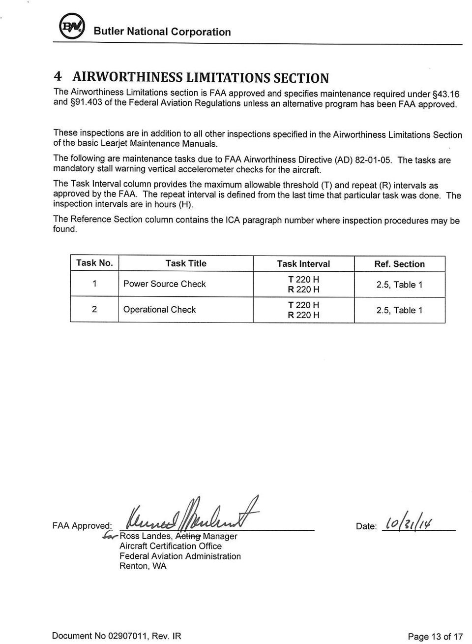
1 ENGINEERING RELEASE DRAWING. NO.: MODEL: LEARJET MODEL 20 AND 35/36 SERIES SHEET: 1 OF 1 Butler National Corporation Olathe, Kansas DRAWING TITLE: INSTRUCTIONS FOR CONTINUED AIRWORTHINESS FOR REPLACEMENT VERTICAL STALL WARNING ACCELEROMETER ON LEARJET MODELS 24,24A/B/24B-A/D/D-A/E/F/F-A, 25,25A/B/C/D/F, 28, 29, 35, 35A, 36, AND 36A AIRPLANES (WITHOUT FC-530 OR FC-535 AUTOPILOTS) REV. OR ITEM RELEASE DATE SUPERCEDED BY RELEASE INFORMATION IR 08/09/14 10/31/14 INITIAL RELEASE REMARKS: FRM036, IR
 REV.")
2 INSTRUCTIONS FOR CONTINUED AIRWORTHINESS FOR Replacement Stall Warning Vertical Accelerometer ON Learjet Models 24/24A/24B/24B A/24C/24D/24E/24F/24F A, 25/25A/25B/25C/25D/25F, 28, 29, 35, 35A, 36, and 36A Airplanes (Without FC 530 or FC 535 Autopilots) Document Number: , Rev. IR Butler National Corporation th St. SW Hangar 201 North Suites Everett, WA Project No. SA12098SE T Rev IR (Initial Release) Approval Date Drawn R. David Lanning 08/18/2014 Checked Chris J. Reedy 08/18/2014 Approved C. Todd Hembree 08/18/2014 Released R. David Lanning 08/19/2014 Document No , Rev. IR Page 1 of 17
 Approval Date Drawn R. David Lanning 08/18/2014 Checked Chris J. Reedy 08/18/2014 Approved C.")
3 Log of Revisions Revision Date Description of Change Approved IR 08/19/2014 Initial Release CTH Butler National Information Disclosure, use or reproduction without the express written permission of Butler National Corporation is prohibited. Copyright 2014 Butler National Corporation. All rights reserved. Butler National Corporation W. 161st Street Olathe, KS Document No , Rev. IR Page 2 of 17

4 TABLE OF CONTENTS 1 INTRODUCTION PURPOSE SCOPE DOCUMENT CONTROL RESTRICTION TO USE CERTAIN DOCUMENTS DEFINITIONS TERMINOLOGY INSTRUCTIONS FOR CONTINUED AIRWORTHINESS INTRODUCTION DESCRIPTION OF ALTERATION CONTROL, OPERATING, AND TESTING INFORMATION SERVICING INFORMATION PERIODIC MAINTENANCE TROUBLESHOOTING INFORMATION REMOVAL AND REPLACEMENT INFORMATION DIAGRAMS SPECIAL INSPECTION REQUIREMENTS Lightning Protection Checks APPLICATION OF PROTECTIVE TREATMENTS DATA RELATIVE TO STRUCTURAL FASTENERS SPECIAL TOOLS ADDITIONAL INSTRUCTIONS OVERHAUL PERIOD ICA REVISION AND DISTRIBUTION ASSISTANCE IMPLEMENTATION AND RECORD KEEPING MAINTENANCE AND SERVICING INSTRUCTIONS INSPECTION PROCEDURES ELECTRICAL BONDING CHECK PROCEDURES AIRWORTHINESS LIMITATIONS SECTION APPENDIX A. EQUIPMENT LOCATION, ELECTRICAL INTERCONNECT, AND IDENTIFICATION Document No , Rev. IR Page 3 of 17

5 1 INTRODUCTION 1.1 Purpose This document is designed for use by the installing facility of the replacement vertical accelerometer Butler National part number , for the stall warning system in the Learjet model 24, 24A, 24B-A, 24C, 24D, 24D-A, 24E, 24F, 24F-A, 25, 25A, 25B, 25C, 25D, 25F, 28, 29, 35, 35A, 36, and 36A (when not equipped with the FC-530 or FC-535 autopilot) as Instructions for Continued Airworthiness in response to 14 CFR Part 25, and 14 CFR Part 25 Appendix G. This ICA includes information required by the operator to adequately maintain the replacement stall warning accelerometer. 1.2 Scope This document identifies the Instructions for Continued Airworthiness for the modification of the aircraft for installation of the replacement stall warning vertical accelerometer, Butler National part number , as provided in the Supplemental Type Certificate. 1.3 Document Control This document shall be released, archived, and controlled in accordance with the Butler National Corporation document control system. When this document is revised, the document will be made available on the Butler National Corporation website. 1.4 Restriction to Use Certain Documents No entity or person applying for approval of an installation of the replacement Stall warning vertical accelerometer may use or reference STC documents or these Instructions for Continued Airworthiness to show compliance with any regulations unless authorized in writing by Butler National Corporation. 1.5 Definitions The following terminology is used within this document: ACO: Aircraft Certification Office LRU: Line Replacement Unit AEG: Aircraft Evaluation Group PMI: Principal Maintenance Inspector CFR: Code of Federal Regulations POI: Principal Operations Inspector FAA: Federal Aviation Administration ICA: Instructions for Continued Airworthiness STC: Supplemental Type Certificate 1.6 Terminology Except where specifically noted, references made to the Vertical Accelerometer will be only to the replacement vertical accelerometer having Butler National part number Document No , Rev. IR Page 4 of 17

6 2 INSTRUCTIONS FOR CONTINUED AIRWORTHINESS 2.1 Introduction Content, Scope, Purpose and Arrangement: This document identifies the Instructions for Continued Airworthiness for the modification of the aircraft by replacement of the stall warning vertical accelerometer with Butler National part number Applicability: Applies to Learjet Model 24, 24A, 24B, 24B-A, 24C, 24D, 24D-A, 24E, 24F, 24F-A, 25, 25A, 25B, 25C, 25D, 25F, 28, 29, 35, 35A, 36, and 36A aircraft not equipped with the FC-530 or FC-535 autopilot when altered by installation of the Vertical Accelerometer in accordance with Butler National Corporation STC. Definition of Abbreviations: See Sections 1.5 and 1.6 Precautions: Units of measurement Referenced publications*: * or later FAA Approved revisions None None Learjet Service Manual, Sections 2 and 7 Learjet Maintenance Manual, Chapter 24 and 27 Learjet Wiring Manual, Chapter 20 Learjet Illustrated Parts Catalog, Chapter 27 Butler National Installation Drawings , Retention: This Document, or the information contained within, will be included in the aircraft permanent records. 2.2 Description of Alteration This project replaces the existing stall warning system vertical accelerometer with the replacement Vertical Accelerometer, Butler National part number , that is the same form, fit and function as the previously approved vertical accelerometer. Note: There is a connector and wiring change: see Butler National Drawing The stall warning system accelerometer provides a sensor input to limit the stall warning pusher force on the yoke. The system design is intended to limit the pusher in case of an erroneous stall indication at high speeds. The Vertical Accelerometer, Butler National part number , is for installation in the stall warning system in the Learjet Model 24, 24A, 24B, 24B-A, 24C, 24D, 24D-A, 24E, 24F, 24F-A, 25, 25A, 25B, 25C, 25D, 25F, 28, 29, 35, 35A, 36, and 36A. 2.3 Control, Operating, and Testing Information Note: The Vertical Accelerometer check is performed with the accelerometer removed from the mounting location. Perform the (Vertical) Accelerometer Power Source and Operational Checks as provided in the references below: Document No , Rev. IR Page 5 of 17

7 On aircraft thru , thru and thru refer to Section 2 of the Service Manual for the Accelerometer Operational Check as well as the Power Source Check as described in Table 1 below. On aircraft , thru , thru , thru , thru and thru refer to Chapter 27 of the Maintenance Manual for the Operational Check of the Stall Warning Accelerometer as well as the Power Source Check as described in Table 1 below. 2.4 Servicing Information Follow the scheduled Power Source and Operational Checks of the stall warning accelerometer at 220 hour intervals. The Learjet Maintenance Manual and Table 1 below identify the Power Source and Operational Check procedures applicable to the aircraft. In the event of system failure, troubleshoot the stall warning system in accordance with Section 2.6 Troubleshooting Information below. Contact Butler National Corporation for any required additional information. 2.5 Periodic Maintenance There is no change to maintenance requirements of the stall warning accelerometer with the installation of the replacement Vertical Accelerometer. The Vertical Accelerometer must be inspected and tested in 220 hour intervals as provided in Table 1 below. Table 1: Maintenance Intervals Item Description/Procedure Interval Equipment Removal & Replacement Removal and replacement of Vertical Accelerometer Removal and replacement instructions are contained in Section 2.7 of this document and in Butler National installation drawing On Condition Document No , Rev. IR Page 6 of 17

8 Item Description/Procedure Interval Power Source Check Perform stall warning vertical accelerometer power check as follows. Vertical accelerometer power will be verified by measuring the DC voltage between accelerometer connector P221 pins A (+) and D (-). 1. Remove the LH nose compartment access door. 2. Remove connector P221 from Stall Warning Vertical Accelerometer assembly Verify that the LH and RH Stall Warning Switches are OFF. 4. Set Battery Switch(es) to ON. (Check for 28 VDC ± 1.0). 5. Verify stall warning power input measures approximately 0VDC (Ground). 6. Set LH Stall Warning Switch to ON. 7. Verify voltage is approximately 28VDC. 8. Set RH Stall Warning Switch to ON. 9. Verify voltage is approximately 28VDC. 10. Set LH Stall Warning Switch to OFF (RH still ON). 11. Verify voltage is approximately 28VDC. 12. Set RH Stall Warning Switch to OFF (both OFF). 13. Verify voltage is approximately 0VDC (ground). Every 220 hours Document No , Rev. IR Page 7 of 17
. 5. Verify stall warning power input measures approximately 0VDC (Ground). 6. Set LH Stall Warning Switch to ON. 7. Verify voltage is approximately 28VDC. 8.")
9 Item Description/Procedure Interval Operational Check Equipment Visual Check Perform stall warning accelerometer operational check as follows: CAUTION Limit this Operational Check to a short duration so as not to overheat the components. 1. Remove the LH nose compartment access door. 2. Remove accelerometer mounting screws 3. Set Battery Switch(es) to ON. (Check for 28 VDC ± 0.5). 4. Set LH Stall Warning Switch to ON. 5. Hold the accelerometer normal side up. 6. Adjust horizontal stabilizer position until a neutral feel of the LH control column is obtained. 7. Move the LH stall vane up. 8. Using a spring scale, observe that the LH control column pusher force reaches 40 to 80 pounds. 9. Rotate accelerometer 180 (upside down from normal). 10. Observe that the column pusher force has reduced to 20 pounds or less. 11. Repeat steps 4 thru 10 using the RH Stall Warning Switch, RH Stall Vane and RH Control Column. 12. If the above conditions are not met, repair or replace system components as required and repeat the Operational Check. 13. If the above conditions are met, reinstall accelerometer (normal side up) and set Stall Warning switches and Battery Switch(es) to OFF. 14. Reinstall the nose compartment access door. 15. Complete the aircraft flight records in accordance with 14 CFR Part Conduct a visual check (see Section 3.1) of the Vertical Accelerometer and its wire harness to ensure continued installation integrity. Inspect the Vertical Accelerometer for security of attachment, including visual inspection of screws and other supporting structure attaching the Vertical Accelerometer to aircraft. Test-Bonding Check Perform an electrical bonding check (See Section 3.2): Perform electrical bond check between the Vertical Accelerometer and separate ground screw on frame and verify that it is less than 2.5 milliohms. Every 220 hours Every 600 hours or 24 months Every 600 hours or 24 months Document No , Rev. IR Page 8 of 17
. 10.")
10 2.6 Troubleshooting Information If erroneous indications occur with respect to the Stall Warning System, consult the applicable Learjet Service manual, Section 2 or Maintenance Manual Chapter Removal and Replacement Information For Vertical Accelerometer removal and replacement instructions, refer to Butler National Installation Drawing, Document If the Vertical Accelerometer is removed and to be reinstalled verify that the Vertical Accelerometer is functioning properly using the Power Source and Operational Checks described above in Table 1. If any work has been performed on the aircraft that could affect the system wiring, or any interconnected equipment, verify the operation of the stall warning per the Stall Warning System checks in the Airplane Flight Manual. 2.8 Diagrams The Vertical Accelerometer installation wiring diagram is contained in Appendix A of this document. 2.9 Special Inspection Requirements Lightning Protection Checks In the event of a suspected or actual lightning strike to the aircraft, perform the Power Source and Operational Checks described in Table 1 above Application of Protective Treatments Not Applicable Data Relative to Structural Fasteners Not Applicable Special Tools For electrical bonding testing; a milliohm meter is required Additional Instructions None Overhaul Period The Vertical Accelerometer does not require overhaul at a specific time period. Power Source and Operational Checks of the Vertical Accelerometer must be performed in 220 hour intervals ICA Revision and Distribution To revise this ICA, Butler National Corporation will distribute revisions to the Instructions for Continued Airworthiness according to the company procedures. The latest revision of this ICA document is available on the Butler National website ( Assistance Flight Standards Inspectors or the certificate holder's PMI have the required resources to respond to questions regarding this ICA. In addition, the customer may refer questions regarding the Vertical Document No , Rev. IR Page 9 of 17

11 Accelerometer and its installation to Butler National Corporation during normal business hours via telephone Implementation and Record Keeping Modification of an aircraft by this Supplemental Type Certificate obligates the aircraft operator to include the maintenance information provided by this document in the operator's aircraft maintenance manual and/or the operator's aircraft scheduled maintenance program. Document No , Rev. IR Page 10 of 17

12 3 MAINTENANCE AND SERVICING INSTRUCTIONS 3.1 Inspection Procedures The maintenance inspections found in Table 1 are carried out using the following Visual Inspection Criteria: General Visual Inspection: A visual inspection that will detect obvious unsatisfactory conditions/discrepancies. This type of inspection may require cleaning, removal of fillets, fairings, access panels/doors, etc. Work stands, ladders, etc. may be required to gain proximity. 1. Metal Parts (all metal parts, bodies, or casings of units in systems and in electrical, instrument, and radio installations, ducting, tubing, rods, and levers). Inspect for the following: a. Cleanliness, external signs of damage, leaks, overheating, discharge, or fluid contamination. b. Obstruction of drainage or vent holes. c. Correct seating and sealing of fairings and serviceability of fasteners. d. Security of attachment, fasteners, and connections. e. Distortion, dents, scores, chafing, pulled or missing fasteners, rivets, bolts, or screws. f. Signs of cracks or wear. g. Separation of bond. h. Failure of welds or spot welds. i. Deterioration of protective treatment and corrosion. 2. Electrical Wires and Components a. Cleanliness, obvious damage, corrosion, security of attachments and connections. b. Overheating or fluid contamination. c. Chaffing of wires and bare or exposed wires. d. Evidence of erosion of connectors, pins, and wires. e. Check terminal ends and connectors for loose or damaged pins. 3.2 Electrical Bonding Check Procedures The maintenance inspections found in Table 1 are carried out using the following maintenance practices: 1. All installed components and equipment should be bonded and grounded to prevent malfunctions of equipment and eliminate electrical spark hazards. 2. Electrical bond measurements should be made from the component under test to primary aircraft structure. If the measured bond resistance exceeds specifications, troubleshoot the installation by measuring the bond resistance of each interface between the tested component and primary structure. 3. Electrical bond measurements should be made with all power off of the aircraft. 4. If it is not possible to make electrical bond measurements with the power off of the aircraft, use the following procedure: a. Measure the resistance with the red lead on unit and black lead on structure. Record this measurement as R1. Document No , Rev. IR Page 11 of 17
.")
13 b. Measure the resistance with the black lead on the unit and the red lead on structure. Record this measurement as R2. c. Average the two measurements. R = (R1 + R2) / 2. d. If R meets the requirement, the installation is acceptable. CAUTION: IF THE SPECIFIED BONDING VALUES ARE NOT MET, REWORK BONDING AREAS IN ACCORDANCE WITH THE PROCEDURES FOUND IN THE BASIC AIRCRAFT WIRING MANUAL. Document No , Rev. IR Page 12 of 17

14
15 Appendix A. EQUIPMENT LOCATION, ELECTRICAL INTERCONNECT, AND IDENTIFICATION A.1 LRU Locations The table below describes the location of the Vertical Accelerometer LRU Description of Location Stall Warning Vertical Accelerometer Frame 2 (Nose Compartment) See Butler National drawing A.2 Electrical Interconnect The diagrams in this Appendix depict the electrical interconnect configurations of the Stall Warning Vertical Accelerometer for the applicable Learjet aircraft. A.3 Wire Marking Codes The electrical wiring diagram also contains the wire marking codes. A.4 Electrical Load Data There is no change to electrical loads information for the replacement Vertical Accelerometer. Document No , Rev. IR Page 14 of 17

16 Figure 1 - Stall Warning Vertical Accelerometer Electrical Interconnect Document No , Rev. IR Page 15 of 17

17 Figure 1 - Stall Warning Vertical Accelerometer Electrical Interconnect, cont d Document No , Rev. IR Page 16 of 17

18 Figure 1 - Stall Warning Vertical Accelerometer Electrical Interconnect, cont d Document No , Rev. IR Page 17 of 17

TELEDYNE BATTERY PRODUCTS. INSTRUCTIONS FOR CONTINUED AIRWORTHINESS and COMPONENT MAINTENANCE MANUAL. For
 TELEDYNE BATTERY PRODUCTS INSTRUCTIONS FOR CONTINUED AIRWORTHINESS and COMPONENT MAINTENANCE MANUAL For TSO-C173/C173a Authorized (GILL ) 7000 Series LT Valve-Regulated Lead-Acid Aircraft Batteries REFER
VAPOR CYCLE FREON AIR-CONDITIONING CHAPTER 05 - TIME LIMITS/INSPECTIONS LIST OF EFFECTIVE PAGES. List of Effective Pages 1 7 June 2007
 CHAPTER 05 - TIME LIMITS/INSPECTIONS LIST OF EFFECTIVE PAGES SECTION PAGE DATE List of Effective Pages 1 7 June 2007 Table of Contents 1-3 05-00-00 601-603 05-11-00 601 and 603 05-11-00 602 7 June 2007
Methods, techniques, and practices contained in manufacturer s Instructions for Continued Airworthiness (ICA),
,") Subject: MAINTENANCE AND ALTERATION Date: 10/7/02 AC : 120-77 DATA Initiated by: AFS-300 Change: 1. PURPOSE. This advisory circular (AC) provides one means, but not the only means, of ensuring that the
Subject: MAINTENANCE AND ALTERATION Date: 10/7/02 AC : 120-77 DATA Initiated by: AFS-300 Change: 1. PURPOSE. This advisory circular (AC) provides one means, but not the only means, of ensuring that the
APPENDIX 2-3 PCAPP EDS INSPECTION LOG SHEETS
 APPENDIX 2-3 PCAPP EDS INSPECTION LOG SHEETS Pueblo Chemical Depot Pueblo Chemical Depot (This page intentionally left blank.) PCAPP EDS Daily (When in Use) Operational Inspection Checklist EXAMPLE Inspected
Manual for Fire Suppression & Methane Detection System
 Manual for Fire Suppression & Methane Detection System Fogmaker North America Post address: 150 Gordon Dr Exton, PA 19341 Delivery address: 150 Gordon Dr Exton, PA 19341 Tel: 610-265-3610 Fax: 610-265-8327
7.1 Safety Precautions-Aircraft and Workshop 3 3 3. 7.2 Workshop Practices 3 3 3
 Note: This module does not apply to category B3. Relevant subject matters for category B3 are defined in module 7B. 7.1 Safety Precautions-Aircraft and Workshop 3 3 3 Aspects of safe working practices
A380-800 SERVICE CHECK (SV3)
") AIRCRAFT REGN: DATE : STN : FLT No : Page No 1 of 9 1 PRELIMINARY ITEMS 1A WARNING: Make sure that the ground safety-locks are correctly installed on the landing gear. This prevents unwanted movement of
AIRCRAFT REGN: DATE : STN : FLT No : Page No 1 of 9 1 PRELIMINARY ITEMS 1A WARNING: Make sure that the ground safety-locks are correctly installed on the landing gear. This prevents unwanted movement of
CIRRUS AIRPLANE MAINTENANCE MANUAL
 UNSCHEDULED MAINTENANCE CHECKS 1. DESCRIPTION The following describes those maintenance checks and inspections on the aircraft which are dictated by special or unusual conditions which are not related
SB96-11B FAA APPROVED Supersedes SB96-11A, SB96-11, M84-16
 TELEDYNE CONTINENTAL AIRCRAFT ENGINE SERVICE ULLETIN Compliance Will Enhance Safety SUJECT: PROPELLER STRIKES AND HYDRAULIC LOCKS. CATEGORY 3 S96-11 FAA APPROVED Supersedes S96-11A, S96-11, M84-16 PURPOSE:
System Saver 318 Air Compressor for Mack E-Tech and ASET Engines
 Maintenance Manual 31 System Saver 318 Air Compressor for Mack E-Tech and ASET Engines Revised 08-05 NON-THROUGH DRIVE THROUGH DRIVE Service Notes About This Manual This manual provides service and repair
Airglas, Inc. MANUAL NO. GLH3000-105-AHSA. MODEL GLH3000 Ski Kit Actuated by Wipaire, Inc. Amphibious Float Hydraulic System
 Airglas, Inc. Amphibious hydraulic system addendum to Instructions for Continued Airworthiness Including Installation, Maintenance and Service Instructions MANUAL NO. GLH3000-105-AHSA MODEL GLH3000 Ski
INSTALLATION AND OPERATING INSTRUCTIONS For Model GL1 Gate Locks
 Securitron Magnalock Corp. www.securitron.com ASSA ABLOY, the global leader Tel 800.624.5625 [email protected] in door opening solutions INSTALLATION AND OPERATING INSTRUCTIONS For Model GL1 Gate
CPL SYSTEMS / GROENEVELD AUTOMATIC GREASING SYSTEM COMPLETE SYSTEM CHECK PNEUMATIC PUMP
 CPL SYSTEMS / GROENEVELD AUTOMATIC GREASING SYSTEM COMPLETE SYSTEM CHECK PNEUMATIC PUMP Feb 5, 2003 1 CPL SYSTEMS / GROENEVELD AUTOMATIC GREASING COMPLETE SYSTEM CHECK - PNEUMATIC PUMP THE SYSTEM DOES
StorTrends 3400 Hardware Guide for Onsite Support
 StorTrends 3400 Hardware Guide for Onsite Support MAN-3400-SS 11/21/2012 Copyright 1985-2012 American Megatrends, Inc. All rights reserved. American Megatrends, Inc. 5555 Oakbrook Parkway, Building 200
Subject: AIRCRAFT ELECTRICAL Date: 11/20/07 AC No. 120-94 WIRING INTERCONNECTION
 U.S. Department of Transportation Federal Aviation Administration Advisory Circular Subject: AIRCRAFT ELECTRICAL Date: 11/20/07 AC No. 120-94 WIRING INTERCONNECTION Initiated by: SYSTEMS TRAINING PROGRAM
Oil and Coolant Circulating Heating System. Model - OCSM
 Oil and Coolant Circulating Heating System Model - OCSM Installation & Operation Manual 216280-000 REV 2 Identifying Your System The HOTSTART heating system is designed to heat fluids for use in marine
PERMIT APPLICATION REQUIREMENTS FOR RESIDENTIAL ROOF MOUNTED PHOTOVOLTAIC SYSTEMS
 Butte County Department of Development Services PERMIT CENTER 7 County Center Drive, Oroville, CA 95965 Main Phone (530)538-7601 Permit Center Phone (530)538-6861 Fax (530)538-7785 FORM NO DBP-71 PERMIT
HG600/HG800. Hydro-Power Unit. Installation and Operation Guide
 HG600/HG800 Hydro-Power Unit Installation and Operation Guide Copyright 04 HydroSpin, All rights reserved. The data contained in this document is proprietary to HydroSpin. It is disclosed to the receiving
OPL BASIC. Dosing System for Professional Laundry machines. Contents
 OPL BASIC Dosing System for Professional Laundry machines Contents 1 Getting Started. Page 2 2 Installation. Page 4 3 Set Up & Operation. Page 8 4 Maintenance & Accessories. Page 10 5 Troubleshooting Page
Installation Instructions for Alarm Module Kit A043F059
 Instruction Sheet 07-2013 Installation Instructions for Alarm Module Kit A043F059 1 Introduction The information contained within is based on information available at the time of going to print. In line
SERVICE BULLETIN No.1103
 SERVICE BULLETIN No.1103 Circulate to listed addressees COACH MODEL BULLETIN TYPE MANUAL & SECTION PARTS BOOK REVISION : T 2100 and C2000 Series : Service Information : Maintenance Manual: Chapter 3 Drive
Mobile Data Power Model: MDP-25
 Mobile Data Power Model: MDP-25 Topic Section Features... 2 Operational Features Summary... 2 Back-up Battery Power Internal Charger Voltage Spike Protection RF Noise Filtering Warning of Imminent Loss
IOM SERIES 820-E/P Electro-Pneumatic Positioner
 FLUID CONTROL DIVISION Parker Hannifin Corporation 95 Edgewood Avenue New Britain, CT 06051 Telephone (860) 827-2300 IOM SERIES 820-E/P Electro-Pneumatic Positioner INSTALLATION, OPERATING & MAINTENANCE
[Docket No. FAA-2009-0411; Directorate Identifier 2008-NM-190-AD; Amendment 39-16095; AD 2009-24-07]
![[Docket No. FAA-2009-0411; Directorate Identifier 2008-NM-190-AD; Amendment 39-16095; AD 2009-24-07]](/thumbs/25/5403875.jpg "[Docket No. FAA-2009-0411; Directorate Identifier 2008-NM-190-AD; Amendment 39-16095; AD 2009-24-07]") [Federal Register: November 27, 2009 (Volume 74, Number 227)] [Rules and Regulations] [Page 62231-62233] From the Federal Register Online via GPO Access [wais.access.gpo.gov] [DOCID:fr27no09-12] DEPARTMENT
[Federal Register: November 27, 2009 (Volume 74, Number 227)] [Rules and Regulations] [Page 62231-62233] From the Federal Register Online via GPO Access [wais.access.gpo.gov] [DOCID:fr27no09-12] DEPARTMENT
Model No. BC460-H Alternator. B & C Specialty Products P.O. Box B Newton, KS 67114 (316) 283-8000
 283-8000") Installation Instructions for Model No. BC460-H Alternator for Lycoming Engines B & C Specialty Products P.O. Box B Newton, KS 67114 (316) 283-8000 BC460-H_Install, Rev. C (12/16/15) NOTE The BC460-H Alternator
Installation Instructions for Model No. BC460-H Alternator for Lycoming Engines B & C Specialty Products P.O. Box B Newton, KS 67114 (316) 283-8000 BC460-H_Install, Rev. C (12/16/15) NOTE The BC460-H Alternator
Geocontrol PRO INSTALLATION AND OPERATION MANUAL. Rev. 1 03/18/04 Part # 11150263
 Geocontrol PRO INSTALLATION AND OPERATION MANUAL Rev. 1 03/18/04 Part # 11150263 TABLE OF CONTENTS Chapter 1: System Description... p. 05 Function and Theory...p. 05 Chapter 2: System Installation... p.
UNIVERSAL LUMBAR INSTALLATION INSTRUCTIONS
 UNIVERSAL LUMBAR INSTALLATION INSTRUCTIONS CONTENTS Parts List... 2 Parts Diagram... 2 Helpful Hints... 3 Installation... 4 Operation and Troubleshooting Guide... 6 Warranty Information... 8 Form #3132,
Advisory Circular. Subject: DAMAGE TOLERANCE INSPECTIONS FOR REPAIRS AND ALTERATIONS. Date: 11/20/07 Initiated by: ANM-100.
 U.S. Department of Transportation Federal Aviation Administration Advisory Circular Subject: DAMAGE TOLERANCE INSPECTIONS FOR REPAIRS AND ALTERATIONS Date: 11/20/07 Initiated by: ANM-100 AC No: 120-93
Nomad WINGS FLAP OPERATING LIMITATIONS
 WINGS FLAP OPERATING LIMITATIONS 1. PLANNING INFORMATION A. Effectivity (1) Aircraft affected: N22 Series line sequence numbers 1 to 9, 11 to 29, 31, 33, 35, 37, 39 to 41, 43, 45, 47 to 59, 63, 65 to 70,
12 Volt 30 Amp Digital Solar Charge Controller
 12 Volt 30 Amp Digital Solar Charge Controller User s Manual WARNING Read carefully and understand all INSTRUCTIONS before operating. Failure to follow the safety rules and other basic safety precautions
DiscPlus DX195 and DX225 Air Disc Brakes
 Revised 11-04 Technical Bulletin Revised 1 Technical 11-04 Bulletin DiscPlus DX195 and DX225 Air Disc Brakes Inspection, Installation and Diagnostics Air Disc Brake Inspection Intervals and Procedures
Fuel Injection Pump, Rotary (005-014)
") Fuel Injection Pump, Rotary View Related Topic Page 1 of 30 Fuel Injection Pump, Rotary (005-014) Table of Contents Summary General Information Preparatory Steps Remove Front Gear Train Rear Gear Train
Fuel Injection Pump, Rotary View Related Topic Page 1 of 30 Fuel Injection Pump, Rotary (005-014) Table of Contents Summary General Information Preparatory Steps Remove Front Gear Train Rear Gear Train
Safe Operating Procedure
 Safe Operating Procedure (Revised 5/14) PERSONAL FALL ARREST SYSTEMS Introduction In 2011, falls to a lower level were the second leading cause of occupational fatalities across all industries, claiming
12 Volt 30 Amp Digital Solar Charge Controller Installation & Operation Manual
 12 Volt 30 Amp Digital Solar Charge Controller Installation & Operation Manual This 30Amp charge controller is designed to protect your 12Volt Lead-acid or Gel-cell battery from being overcharge by solar
DRAFT (Public comments phase August 2006) Date: XX/XX/XX. Initiated by: ANE-110
 Date: XX/XX/XX. Initiated by: ANE-110") (Public comments phase August 2006) Advisory Circular Subject: PROPOSED DRAFT Turbine Engine Repairs and Alterations Approval of Technical and Substantiation Data Date: XX/XX/XX Initiated by: ANE-110 AC
(Public comments phase August 2006) Advisory Circular Subject: PROPOSED DRAFT Turbine Engine Repairs and Alterations Approval of Technical and Substantiation Data Date: XX/XX/XX Initiated by: ANE-110 AC
Memorandum Date: February 5, 2014
 Federal Aviation Administration Memorandum Date: February 5, 2014 To: From: Subject: Memo No.: See Distribution List David W. Hempe, Manager, Aircraft Engineering Division, AIR-100 James D. Seipel, Manager,
Operating Manual. Los Angeles Abrasion Machine HM-70A & HM-70AF
 Operating Manual Los Angeles Abrasion Machine HM-70A & HM-70AF Rev: 07/19/2012 PHONE: 800-444-1508 P.O. Box 200, Lewis Center, Ohio 43035-0200 FAX: 800-255-5314 740-548-7298 E-mail: [email protected]
I nstallation. M100Q Series Proportional Actuator with R81Q Controller Board for Thermistor Sensor Applications. Tools Needed.
 FANs 268.1, 1628.3 Installation Bulletin M100Q Issue Date 1099 M100Q Series Proportional Actuator with R81Q Controller Board for Thermistor Sensor Applications I nstallation Parts Included M110QGA-1 and
ADDENDUM USER MANUAL LBV300S-6, LBV300XL & LBV600XL
 ADDENDUM USER MANUAL LBV300S-6, LBV300XL & LBV600XL DOCS-004 Rev C The information, photographs, illustrations and descriptions contained in this manual are the property of SeaBotix Inc. Unauthorized duplication
Rail Vehicle Systems IP-241. Rev 07 3/9/2016 - en. Installation and Maintenance Guide. Slack Adjuster Model KRD-482-E and KRD-482-R P/N 783901, 790196
 Rail Vehicle Systems IP-241 Rev 07 3/9/2016 - en Installation and Maintenance Guide Slack Adjuster Model KRD-482-E and KRD-482-R P/N 783901, 790196 Contact Address New York Air Brake 748 Starbuck Avenue
CROWN BOILER COMPANY BWF SERIES BOILER CATEGORY I VENT KIT INSTALLATION AND OPERATING INSTRUCTIONS
 CROWN BOILER COMPANY BWF SERIES BOILER CATEGORY I VENT KIT INSTALLATION AND OPERATING INSTRUCTIONS WARNING Improper installation, adjustment, alteration, service, or maintenance of this product can cause
CHAPTER 10 PARKING AND STORAGE. Section Title Page
 CHAPTER 10 PARKING AND STORAGE Section Title Page 10-10 Parking.......................................... 10.1 10-11 Parking in High Wind or Turbulent Air............. 10.1 10-12 Main Rotor Blade Tie-Downs....................
http://waterheatertimer.org/troubleshoot-rheem-tankless-water-heater.html
 http://waterheatertimer.org/troubleshoot-rheem-tankless-water-heater.html TECHNICAL SERVICE DEPARTMENT Removal, Cleaning, & Reinstallation of the Burner Assembly For models 74 & GT199 Required tools -
[Docket No. FAA-2015-3983; Directorate Identifier 2015-NM-141-AD] Airworthiness Directives; The Boeing Company Airplanes
![[Docket No. FAA-2015-3983; Directorate Identifier 2015-NM-141-AD] Airworthiness Directives; The Boeing Company Airplanes](/thumbs/24/3955211.jpg "[Docket No. FAA-2015-3983; Directorate Identifier 2015-NM-141-AD] Airworthiness Directives; The Boeing Company Airplanes") This document is scheduled to be published in the Federal Register on 10/06/2015 and available online at http://federalregister.gov/a/2015-25272, and on FDsys.gov [4910-13-P] DEPARTMENT OF TRANSPORTATION
This document is scheduled to be published in the Federal Register on 10/06/2015 and available online at http://federalregister.gov/a/2015-25272, and on FDsys.gov [4910-13-P] DEPARTMENT OF TRANSPORTATION
Series 510 Submersible Level Transmitters
 Series 510 Submersible Level Transmitters The Series 510 Submersible Level Transmitters are solid state instruments designed for direct submergence into many types of liquid for quick, accurate and reliable
Electronically Controlled Air Suspension (ECAS) for Trucks
 for Trucks") $2.50 Electronically Controlled Air Suspension (ECAS) for Trucks Maintenance Manual No. 36 Issued 7-99 ECAS System for 6 x 2 and 6 x 4 Vehicles with Rear Air Suspensions Service Notes Service Notes This
$2.50 Electronically Controlled Air Suspension (ECAS) for Trucks Maintenance Manual No. 36 Issued 7-99 ECAS System for 6 x 2 and 6 x 4 Vehicles with Rear Air Suspensions Service Notes Service Notes This
Owner s Manual & Safety Instructions
 Owner s Manual & Safety Instructions Save This Manual Keep this manual for the safety warnings and precautions, assembly, operating, inspection, maintenance and cleaning procedures. Write the product s
SureSite Magnetic Liquid Level Indicator
 SureSite Magnetic Liquid Level Indicator Instruction Bulletin No. 177664-1 (Rev. E) Section 1: Weldments Thank you for purchasing the GEMS SureSite Magnetic Level Indicator. Please read this document prior
ADM1TE 5/30A DIN rail single phase two wire energy meter
 ADMTE 5/30A DIN rail single phase two wire energy meter. Safety instruction.2 Foreword.3 Performance criteria.4 Specifications.5 Basic errors.6 Description.7 Dimensions.8 Installation.9 Operating.0 Troubleshooting.
TOYOTA TECHNICAL. An example of a tire pressure monitor valve sub-assembly. This mounts to a drop area in the wheel.
 TOYOTA TIRE PRESSURE WARNING SYSTEM Toyota uses various tire pressure warning systems. Here, we ll discuss the system featured on the 2006 Land Cruiser. Combination meter warning reset switch warning reset
3. SEISCO PARTS & SERVICE REMOVAL AND REPAIR GUIDE
 4 3. SEISCO PARTS & SERVICE REMOVAL AND REPAIR GUIDE A. Changing the Control Board B. Replacing a Heating Element C. Thermistor Replacement D. High Limit Switch Replacement E. Level Detector Replacement
CR-SERIES CARPET POLES INSTRUCTION MANUAL
 VESTIL MANUFACTURING CORP. 2999 North Wayne Street, P.O. Box 507, Angola, IN 46703 Telephone: (260) 665-7586 -or- Toll Free (800) 348-0868 Fax: (260) 665-339 www.vestilmfg.com e-mail: [email protected]
INSTALLATION MANUAL INSIDE PASSENGER COMPARTMENT. HFC 134a FOR EUROPEAN SPEC. / GENERAL SPEC. AIR CONDITIONING ENGLISH
 HFC 134a Ozone Friendly Refrigerant FOR EUROPEAN SPEC. / GENERAL SPEC. AIR CONDITIONING ENGLISH AAAMU-60 / INSIDE PASSENGER COMPARTMENT INSTALLATION MANUAL 2000 (EUROPE) B.V.. All Rights Reserved. This
Not required for most applications Not required for most applications High pressure (12-803 provided) High pressure (12-803 provided)
 High pressure (12-803 provided)") ELECTRIC FUEL PUMPS P/N 12-801-1, 712-801-1, 12-802-1, 712-802-1, 12-815-1, & 712-815-1 FUEL PRESSURE REGULATORS P/N 12-803, 12-501, 12-804, 12-500, & 15812NOS Installation Instructions THESE INSTRUCTIONS
ELECTRIC FUEL PUMPS P/N 12-801-1, 712-801-1, 12-802-1, 712-802-1, 12-815-1, & 712-815-1 FUEL PRESSURE REGULATORS P/N 12-803, 12-501, 12-804, 12-500, & 15812NOS Installation Instructions THESE INSTRUCTIONS
SERVICE MANUAL 12VDC WALL THERMOSTAT AIR CONDITIONING SYSTEMS ROOFTOP UNITS ONLY
 SERVICE MANUAL 12VDC WALL THERMOSTAT AIR CONDITIONING SYSTEMS ROOFTOP UNITS ONLY! WARNING - SHOCK HAZARD! TO PREVENT THE POSSIBILITY OF SEVERE PERSONAL INJURY, DEATH, OR EQUIPMENT DAMAGE DUE TO ELECTRICAL
OPERATING MANUAL CONTRACTOR STYLE AXIAL FANS
 Manual No. BLWR043 Rev. 4 September 2012 OPERATING MANUAL CONTRACTOR STYLE AXIAL FANS CVF-8AC CVF-8AC50 CVF-6ACAN CVF-15ACAN CVF-25ACAN CVF-8A15KIT CVF-8A25KIT MODELS: CVF-8DC CVF-6DCAN CVF-15DCAN CVF-25DCAN
NOTE WARNING. Electric Leveling Motor Brake Replacement Instructions ELECTRIC LEVELING MOTOR BRAKE REPLACEMENT INSTRUCTIONS. Content.
 ELECTRIC LEVELING MOTOR BRAKE REPLACEMENT INSTRUCTIONS Content Contents Inspection 1 Installation 2 System Test 5 Inspection is not required for boots with metal clamps (FIGURE 4) or boots with an extra
REPAIR INSTRUCTIONS UNDER BODY CYLINDER (UM, UL)
") Table of contents 1. Introduction... 3 1.1. Scope of use... 3 1.2. General remarks... 3 1.3. Contact Hyva... 3 1.4. Precautions... 4 1.5. Spare parts... 4 1.5.1. Prior to use... 4 1.6. Recycling and Reuse
Table of contents 1. Introduction... 3 1.1. Scope of use... 3 1.2. General remarks... 3 1.3. Contact Hyva... 3 1.4. Precautions... 4 1.5. Spare parts... 4 1.5.1. Prior to use... 4 1.6. Recycling and Reuse
Express5800/120Ed. Rack Mount Kit Installation Procedures PN: 455-01607-001
 Express5800/120Ed Rack Mount Kit Installation Procedures PN: 455-01607-001 Proprietary Notice and Liability Disclaimer The information disclosed in this document, including all designs and related materials,
Bold items are particular to the City of Euless
 EULESS FIRE DEPARTMENT FIRE MARSHAL S OFFICE INFORMATION LINE: Revised 2/12 Fire Chief Wes Rhodes Fire Marshal Paul Smith EFD-FMO 3-2 2009 International Fire & Building Code as Amended NFPA Standards Adopted
G670 Intermittent Pilot Ignition Controls
 Installation Sheets Manual 121 Gas Combustion Combination Controls and Systems Section G Technical Bulletin Issue Date 0300 Intermittent Pilot Ignition Controls Figure 1: Intermittent Pilot Ignition Control
Models SFP33 & SFP32 Pressure Transmitters
 SFP33 Flow-Through Pressure Transmitter SFP32 Single-Ended Pressure Transmitter DS-PR-SFP-eng April, 2016 Data Sheet Models SFP33 & SFP32 Pressure Transmitters Pressure Brooks Seal Free Pressure Measurement
EVANS ELECTRONIC TEMPERATURE CONTROL TROUBLESHOOTING GUIDE for systems equipped with electric coolant valve and external PC board.
 EVANS ELECTRONIC TEMPERATURE CONTROL TROUBLESHOOTING GUIDE for systems equipped with electric coolant valve and external PC board. This Troubleshooting Guide covers the electric coolant valve and control
SAFETY & OPERATING INSTRUCTIONS
 SAFETY & OPERATING INSTRUCTIONS EDLUND TOMATO LASER, Models ETL -316, -140 & -380 READ AND UNDERSTAND THIS MANUAL AND ALL INSTRUCTIONS BEFORE OPERATING THIS SLICER. 159 Industrial Parkway, Burlington,
HP ProLiant DL380 G6 Carrier-Grade Server Read Before Install
 HP ProLiant DL380 G6 Carrier-Grade Server Read Before Install Carrier-Grade Instructions HP Part Number: AM275-9001A Published: July 2012 Edition: 3 Copyright 2009, 2012 Hewlett-Packard Development Company,
Massoud Sadeghi: [email protected]. (425)227-2117 Brett Portwood: [email protected] (562)627-5350. Transport Airplane Directorate; ANM-117
227-2117 Brett Portwood: brett.portwood@faa.gov (562)627-5350. Transport Airplane Directorate; ANM-117") Massoud Sadeghi: [email protected] FAA Aging Systems Program Manager Transport Airplane Directorate; ANM-117 (425)227-2117 Brett Portwood: [email protected] FAA Technical Specialist for Safety
Massoud Sadeghi: [email protected] FAA Aging Systems Program Manager Transport Airplane Directorate; ANM-117 (425)227-2117 Brett Portwood: [email protected] FAA Technical Specialist for Safety
HEAD HARNESS & BUCKELS
 THIS INSPECTION AND MAINTENANCE SHOULD BE PERFORMED AT LEAST ANNUALLY AND AS DICTATED BY CONDITION REVEALED DURING DAILY/MONTHLY INSPECTION. MONTHLY INSPECTIONS DETERMINE NECESSITY FOR OVERHAUL WITH MORE
UT202A Operating Manual. Contents
 Title Contents Page Overview Unpacking Inspection Safety Information Rules for Safe Operation International Electrical Symbols The Meter Structure Functional Buttons and auto power off Display Symbols
COMMERCIAL GAS DRYER
 COMMERCIAL GAS DRYER MODELS CGM2751TQ0 (WHITE) CGM2751TQ1 (WHITE) 5 12 Litho in U.S.A. (CMS) (psw) c 2012 WHIRLPOOL CORPORATION Part No. W10119631 Rev. C TOP AND CONSOLE PARTS W10119631 2 TOP AND CONSOLE
Companion Service Guide
 Companion Service Guide This Service Guide contains: Troubleshooting Replacement Instructions Contact Information Golden Technologies 401 Bridge Street Old Forge, PA 18518 Toll-free: 800-624-6374 Fax:
Technical Update TAA.TU.11093 Rev. 1
 http://www.gambro.com/en/usa_tech/ 800-525-2623 303-222-6500 Technical Update TAA.TU.11093 Rev. 1 Effective: 05 APR 2013 CO# 13084 Product: Subject: From: Phoenix Dialysis System Required Electrical Safety
BERMAD Fire Protection
 400E-2M/700E-2M IOM Bermad Electrically Controlled Deluge Valve with EasyLock Manual Reset Model: 400E-2M/700E-2M INSTALLATION OPERATION MAINTENANCE Application Engineering BERMAD 400E-2M/700E-2M Bermad
BC-5000 OPERATIONS MANUAL BATTERY CAPACITY TESTER COFKO LLC.
 BC-5000 BATTERY CAPACITY TESTER OPERATIONS MANUAL COFKO LLC. COPYRIGHT 2010 1 UNPACKING As you unpack your new BC-5000 battery capacity tester, inspect the tester for signs of shipping damage. If shipping
Service manual. Website: www.andico.com.au CAUTION - BEFORE SERVICING THE UNIT, READ THE SAFETY - PRECAUTIONS IN THIS MANUAL.
 Website: www.andico.com.au Service manual CAUTION - BEFORE SERVICING THE UNIT, READ THE SAFETY - PRECAUTIONS IN THIS MANUAL. - ONLY FOR AUTHORISED SERVICE PERSONNEL. MODELS: MPK1-09CR-QB8 MPK1-12ER-QB6
[Docket No. FAA-2015-1990; Directorate Identifier 2015-NM-027-AD; Amendment. AGENCY: Federal Aviation Administration (FAA), DOT.
, DOT.") This document is scheduled to be published in the Federal Register on 01/13/2016 and available online at http://federalregister.gov/a/2016-00004, and on FDsys.gov [4910-13-P] DEPARTMENT OF TRANSPORTATION
This document is scheduled to be published in the Federal Register on 01/13/2016 and available online at http://federalregister.gov/a/2016-00004, and on FDsys.gov [4910-13-P] DEPARTMENT OF TRANSPORTATION
Maintenance Report MEDIUM VOLTAGE POWER STATION 500SC / 630SC / 800SC / 900SC / 1000 1SC / 1000 2SC / 1250SC / 1600SC / 1800SC / 2000SC
 Maintenance Report MEDIUM VOLTAGE POWER STATION 500SC / 630SC / 800SC / 900SC / 1000 1SC / 1000 2SC / 1250SC / 1600SC / 1800SC / 2000SC Project name: Customer: Address, location of the system: Serial number
Model 1756 Test Lead Kit
 Keithley Instruments 28775 Aurora Road Cleveland, Ohio 44139 1-888-KEITHLEY http://www.keithley.com Model 1756 Test Lead Kit Gerneral Purpose Test Lead Information Description These test leads allow you
i ChatterBox! Motorcycle Security
 i Before you Start the Installation * Please read this manual to become familiar with the requirements necessary to complete the installation. * Use a high quality multi-meter to test all wires before
SELF-STEERING AXLE TABLE OF CONTENTS
 SELF-STEERING AXLE TABLE OF CONTENTS Section 1 - Introduction Section 2 - Pre-Installation Check List Section 3 - Ride Height Adjustments Section 4 - Suspension Mount Section 5 - Axle Mount Section 6 -
Recall R136 Front Lower Ball Joints Check Torque or Replace
 SERVICE DATE /00 Amended /00 TECHNICAL BULLETIN Recall R6 Front Lower Ball Joints Check Torque or Replace MODEL VIN Remove and destroy Bulletin S04-R6, dated /00. Replace with this Bulletin. Revisions
COMPONENTS IP 2 INSTRUMENT PANEL INSTRUMENT PANEL ASSEMBLY ASSIST GRIP RETAINER RH FRONT PILLAR GARNISH RH FRONT DOOR OPENING TRIM WEATHERSTRIP RH
 INSTRUMENT PANEL INSTRUMENT PANEL INSTRUMENT PANEL PRECAUTION 1 1. PRECAUTION FOR VEHICLE WITH SRS AIRBAG AND SEAT BELT PRETENSIONER (a) Some of these operations may affect the SRS airbag system. Read
Installation Instructions
 520 Installation Instructions Thank you very much for purchasing PIAA product. Please read this entire manual before installation and use of this product. For Installers Please give this Installation Manual
DRM75A 230V 20/100A DIN rail single phase two wire energy meter
 DRM75A 230V 20/100A DIN rail single phase two wire energy meter 1.1 Safety instruction 1.2 Foreword 1.3 Performance criteria 1.4 Specifications 1.5 Basic errors 1.6 Description 1.7 Dimensions 1.8 Installation
2003 ACCORD - Automatic Transmission Removal
 2003 ACCORD - Automatic Transmission Removal Special Tools Required Engine support hanger, A and Reds AAR-T-12566 Engine hanger balancer bar VSB02C000019 Front subframe adapter VSB02C000016 These special
INSPECTION IN-PROCESS AND FINAL QUALITY ASSURANCE
 INSPECTION IN-PROCESS AND FINAL QUALITY ASSURANCE 1.0 SCOPE: The purpose of this procedure is to document mandatory to ensure compliance to Project Requirements. inspection points and 2.0 REFERENCE DOCUMENTS:
-1- SPECIFICATIONS 002085 CONE SETTER PLATFORM ATTACHMENT INDEX
 -1-002085 CONE SETTER PLATFORM ATTACHMENT INDEX I. GENERAL EQUIPMENT : A. Intent Statement B. Cone Setter Platform II. III. 1. Understructure Frame 2. Mounting Components 3. Paint 4. Basket 5. Labels 6.
Aloha Airlines Flight 243 Boeing 737-200 April 28,1988 Honolulu, HI
 Aloha Airlines Flight 243 Boeing 737-200 April 28,1988 Honolulu, HI Aloha 243 was a watershed accident : There were very clear precursors that were not acted upon It reflected a basic lack of airplane
FLY SYNTHESIS STORCH HS-CL
 STORCH HS-CL MAINTENANCE MANUAL (ALID FOR ROTAX 912 UL AND JABIRU 2200 ENGINES) 00 28/05/07 New manual issue Num. Date Description Issued erify Approvation REISION The FlySynthesis s.r.l. it reserves him
HM-W536 Install Guide
 HM-W536 Install Guide 9/13/2013 IMPORTANT SAFETY INSTRUCTIONS Warning - When using electrical devices, basic safety precautions should be followed to reduce the risk of fire, electrical shock or injury.
2013 VTech Printed in China 91-009656-000 US
 Rechargeable Power Pack User s Manual 2013 VTech Printed in China 91-009656-000 US INTRODUCTION The Rechargeable Power Pack makes it easier than ever to keep the InnoTab 3 or InnoTab 3S charged and ready
5800 Temperature Sensor Cable Assembly
 5800 Temperature Sensor Cable Assembly Removal and Replacement Instruction Sheet #60-4702-070 Revision D, January 14, 2013 Overview The 5800 has two refrigeration temperature sensors, one attached to the
STORED PRESSURE STAINLESS STEEL
 STORED PRESSURE STAINLESS STEEL WATER FIRE EXTINGUISHERS Model 240-2-1/2 Gallon OWNER'S SERVICE MANUAL NO. 05601 INSPECTION, MAINTENANCE AND RECHARGE All fire extinguishers should be installed, inspected
SERVICE. 28R-7135001 thru 28R-7135229 PA-28R-200 Arrow II 28R-7235001 thru 28R-7635545
 Piper Aircraft, Inc. 2926 Piper Drive Vero Beach, Florida, U.S.A. 32960 SERVICE NO. 1242 BULLETIN PIPER CONSIDERS COMPLIANCE MANDATORY Date: January 30, 2015 (S) (M) Service Bulletin (SB) 1242 supersedes
Assessment Specifications for Remotely Piloted Aircraft Systems, Class 1 AS-RPAS1
 AMC Civil Aviation Authority The Netherlands Assessment Specifications for Remotely Piloted Aircraft Systems, Class 1 AS-RPAS1 Version 1.1 1 December 2014-1 - CONTENTS (general layout) AS RPAS1 REMOTELY
TraceTek TTDM Series Leak Detection and Location Modules Replacement Parts Installation Instructions
 TraceTek TTDM Series Leak Detection and Location Modules Replacement Parts Installation Instructions TRACETEK TraceTek TTDM Replacement Parts General Information These instructions detail the steps to
60 WATT LED TRIPLE BEAM WORKLIGHT
 60 WATT LED TRIPLE BEAM WORKLIGHT OWNER S MANUAL WARNING: Read carefully and understand all ASSEMBLY AND OPERATION INSTRUCTIONS before operating. Failure to follow the safety rules and other basic safety
GENUINE PARTS INSTALLATION INSTRUCTIONS
 GENUINE PARTS INSTALLATION INSTRUCTIONS DESCRIPTION: Illuminated Kick Plate APPLICATION: Rogue (2011) PART NUMBER: 999G6 GX010 KIT CONTENTS: Item A B C G H QTY 1 1 1 D 1 E 1 F 3 15 6 Description Kick Plate,
Owner's Copy. 104873 December 14, 2011 ELECTRICAL INSTRUCTIONS FOR ADVANTEX EA OR EX MODELS
 104873 December 14, 2011 Detex Corporation, 302 Detex Drive, New Braunfels, Texas 78130-3045 (830)629-2900 / 1-800-729-3839 / Fax (830)620-6711 E-MAIL: [email protected] INTERNET: www.detex.com ELECTRICAL
http://www.180skills.com/
 http://www.180skills.com/ Revised April 2012 Copyright 2012 180 Skills LLC All Rights Reserved This document and its content is copyright of 180 Skills LLC 2011. All rights reserved. Any redistribution