Application Note 82 Using the Dallas Trickle Charge Timekeeper
|
|
|
- Justin Price
- 10 years ago
- Views:
Transcription
1 Application Note 82 Using the Dallas Trickle Charge Timekeeper DESCRIPTION The Dallas Semiconductor/Maxim real-time clock (RTC) family contains a number of parts within an integrated trickle-charging circuit. This application note describes the operation of the DS1302 trickle charger. Most of the data in this note can be applied to other Dallas RTC trickle chargers, with a few circuit-specific changes. Figure 1. DS1302 PROGRAMMABLE TRICKLE CHARGER 1 of

2 TRICKLE CHARGER The trickle charge circuit is shown in Figure 1 along with the trickle charge register. To enable the trickle charger, the desired path through the circuit must be selected and the appropriate pattern written to the trickle charge register. The trickle charge select (TCS) bits (bits 4 to 7) control the selection of the trickle charger. In order to prevent accidental enabling, only a pattern of 1010 enables the trickle charger. All other patterns disable the trickle charger. The DS1302 powers up with the trickle charger disabled. The diode select (DS) bits (bits 2 to 3) select whether one diode or two diodes are connected between V CC2 and V CC1. If DS is 01, one diode is selected or if DS is 10, two diodes are selected. If DS is 00 or 11 the trickle charger is disabled independently of TCS. The RS bits (bits 0 to 1) select the resistor that is connected between V CC2 and V CC1. The resistor selected by the resistor select (RS) bits is as follows: RS BITS RESISTOR TYPICAL VALUE 00 None None 01 R1 2kΩ 10 R2 4kΩ 11 R3 8kΩ If RS is 00 the trickle charger is disabled independently of TCS. The user determines diode and resistor selection according to the maximum current desired for battery or super cap charging. The maximum charging current can be calculated as illustrated in the following example. Assume that a system power supply of 5V is applied to V CC2 a and a super cap is connected to V CC1. Also, assume that the trickle charger has been enabled with one diode and resistor R1 between V CC2 and V CC1. The maximum current I MAX would, therefore, be calculated as follows: I MAX = (5.0V - diode drop) / R1 ~(5.0V 0.7V) / 2kΩ ~2.2mA Obviously, as the super cap charges, the voltage drop between V CC2 and V CC1 decreased and, therefore, the charge current decreases. See curves in Trickle Charge Characteristics. POWER CONTROL The DS1302 can be powered in several different ways. The first method, shown in Figure 2, illustrates the DS1302 being supplied by only one power supply. In Figure 2a, the power supply is connected to V CC2 (pin 1) and in Figure 2b the power supply is connected to V CC1 (pin 8). In each case, the unused power pin, V CC1 or V CC2, is grounded. The second method, Figure 3, illustrates the DS1302 being backed up using a nonrechargeable battery connected to V CC1. In these two cases the trickle charge circuit has been disabled. In the final case, Figure 4, the DS1302 is being backed up by connecting a super cap, Figure 4a, or a rechargeable battery, Figure 4b, to V CC1. In this case, the trickle charge circuit has been enabled. 2 of 9

3 Figures 2a and 2b. SINGLE POWER SUPPLY OPTION Figure 3. NONRECHARGABLE BATTERY BACKUP Figures 4a and 4b. SUPER CAP OR RECHARGABLE BATTERY BACKUP 3 of 9

4 TRICKLE CHARGE CHARACTERISTICS Charging the Super Cap The maximum current, I MAX, required by the trickle charge circuit can be calculated by inserting the correct values selected in the trickle charge register into the following equation I MAX = (V CC2 - diode drop) / R Table 1 contains the values of I MAX for V CC2 values of 4.5V, 5.0V, and 5.5V; 1 diode drop and 2 diode drops; resistor values of 2000Ω, 4000Ω and 8000Ω. Also, the charging current can be modeled as a function of charge time. Both the super cap voltage and charging current as a function of time are represented in Figure 5. The equation to model the super cap voltage as a function of time is where V(t) = V MAX [1 - e (-t / RC) ] V(t) = Super Cap Voltage V MAX = (V CC2 - n Diode Drops), n = 1, 2 R = Internal Trickle-Charge Resistor C = Super Cap Capacitance The time needed to charge the super cap to 95% of V MAX is given in Table 2. Note that the time required to charge the super cap to 95% of the value of V MAX is independent of the value of V MAX. The equation, which models the charging current as a function of time, is given as where I(t) = V MAX / R x e (-t / RC) I(t) = Charging Current V MAX = (V CC2 - n Diode Drops), n = 1, 2 R = Internal Trickle-Charge Resistor C = Super Cap Capacitance 4 of 9

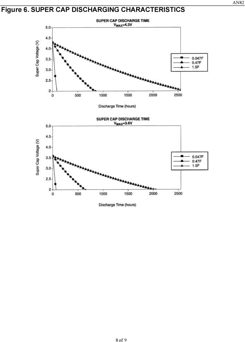
5 Discharging the Super Cap When modeling the DS1302 for the time to discharge the super cap, the DS1302 characterization data was used to observe that the I CC1T, timekeeping current through V CC1, was linear. This implies that it is proper to represent the DS1302 as a resistive load, R L, through which the super cap is discharged. Using the data sheet spec of I CC1T max of 0.3µA at 2.0 V CC1 gives a value for R L of 6.7MΩ. Then the equation modeling the discharging of the super cap is given by where V(t) = V MAX x e (-t / R L C) V(t) = Super Cap Voltage V MAX = (V CC2 - n Diode Drops), n = 1, 2 R L = DS1302 Load Resistance C = Super Cap Capacitance The calculated values for the time required to discharge the super cap to 2V are given in Table 3 and a sample of the super cap voltage as a function of discharge time is given in Figure 6. Figure 7 shows the typical I CC1T current versus voltage at +25 C. 5 of 9
 = V MAX x e (-t / R L C) V(t) = Super Cap Voltage V MAX = (V CC2 - n Diode Drops), n = 1, 2 R L = DS1302 Load")
6 Table 1. CALCULATED VALUES OF I MAX V CC2 (V) 2000W 4000W 8000W 1 diode 2 diodes 1 diode 2 diodes 1 diode 2 diodes UNITS ma ma ma Table 2. CHARGING TIME FOR SUPER CAP TO 95% OF V MAX CHARGE TIME 2000W 4000W 8000W UNITS Super Cap = minutes Super Cap = 0.47F minutes Super Cap = 1.5F minutes Table 3. SUPER CAP DISCHARGE TIME TO 2V V CC2 (V) 0.047F 0.47F 1.5F 1 diode 2 diodes 1 diode 2 diodes 1 diode 2 diodes UNITS hours hours hours 6 of 9

7 Figure 5. SUPER CAP CHARGING CHARACTERISTICS Charge Voltage (V) 7 of 9

8 Figure 6. SUPER CAP DISCHARGING CHARACTERISTICS 8 of 9
9 Figure 7. DS1302 AVERAGE I CC1T at +25 C average VCC1 (V) 9 of 9

DS1302 Trickle-Charge Timekeeping Chip
 DS1302 Trickle-Charge Timekeeping Chip BENEFITS AND FEATURES Completely Manages All Timekeeping Functio o Real-Time Clock Counts Seconds, Minutes, Hours, Date of the Month, Month, Day of the Week, and
DS1307ZN. 64 x 8 Serial Real-Time Clock
 DS137 64 x 8 Serial Real-Time Clock www.maxim-ic.com FEATURES Real-time clock (RTC) counts seconds, minutes, hours, date of the month, month, day of the week, and year with leap-year compensation valid
Supply voltage Supervisor TL77xx Series. Author: Eilhard Haseloff
 Supply voltage Supervisor TL77xx Series Author: Eilhard Haseloff Literature Number: SLVAE04 March 1997 i IMPORTANT NOTICE Texas Instruments (TI) reserves the right to make changes to its products or to
Application Note 58 Crystal Considerations with Dallas Real Time Clocks
 www.dalsemi.com Application Note 58 Crystal Considerations with Dallas Real Time Clocks Dallas Semiconductor offers a variety of real time clocks (RTCs). The majority of these are available either as integrated
2.996/6.971 Biomedical Devices Design Laboratory Lecture 4: Power Supplies
 2.996/6.971 Biomedical Devices Design Laboratory Lecture 4: Power Supplies Instructor: Dr. Hong Ma Sept. 19, 2007 Key Problem Ideal voltage sources do not exist! Voltage regulators use feedback to reduce
PACKAGE OUTLINE DALLAS DS2434 DS2434 GND. PR 35 PACKAGE See Mech. Drawings Section
 PRELIMINARY DS2434 Battery Identification Chip FEATURES Provides unique ID number to battery packs PACKAGE OUTLINE Eliminates thermistors by sensing battery temperature on chip DALLAS DS2434 1 2 3 256
LM1084 5A Low Dropout Positive Regulators
 5A Low Dropout Positive Regulators General Description The LM1084 is a series of low dropout voltage positive regulators with a maximum dropout of 1.5 at 5A of load current. It has the same pin-out as
DS1220Y 16k Nonvolatile SRAM
 19-5579; Rev 10/10 NOT RECOENDED FOR NEW DESIGNS 16k Nonvolatile SRAM www.maxim-ic.com FEATURES 10 years minimum data retention in the absence of external power Data is automatically protected during power
HANDLING SUSPEND MODE ON A USB MOUSE
 APPLICATION NOTE HANDLING SUSPEND MODE ON A USB MOUSE by Microcontroller Division Application Team INTRODUCTION All USB devices must support Suspend mode. Suspend mode enables the devices to enter low-power
Type EDL, Electric Double Layer Supercapacitors Ultra High Capacitance, Small Case Size Options
 Ultra High Capacitance, Small Case Size Options Type EDL electric double layer supercapacitors offer extremely high capacitance values (farads) in a variety of packaging options that will satisfy, low
LM134-LM234 LM334 THREE TERMINAL ADJUSTABLE CURRENT SOURCES. OPERATES from 1V to 40V
 LM134-LM234 LM334 THREE TERMINAL USTABLE CURRENT SOURCES OPERATES from 1 to 40. 0.02% CURRENT REGULATION PROGRAMMABLE from 1µA to 10mA ±3% INITIAL ACCURACY DESCRIPTION The LM134/LM234/LM334 are 3-terminal
Application Note 58 Crystal Considerations for Dallas Real-Time Clocks
 www.maxim-ic.com Application Note 58 Crystal Considerations for Dallas Real-Time Clocks OVERVIEW This application note describes crystal selection and layout techniques for connecting a 32,768Hz crystal
Rectifier circuits & DC power supplies
 Rectifier circuits & DC power supplies Goal: Generate the DC voltages needed for most electronics starting with the AC power that comes through the power line? 120 V RMS f = 60 Hz T = 1667 ms) = )sin How
MM74C150 MM82C19 16-Line to 1-Line Multiplexer 3-STATE 16-Line to 1-Line Multiplexer
 MM74C150 MM82C19 16-Line to 1-Line Multiplexer 3-STATE 16-Line to 1-Line Multiplexer General Description The MM74C150 and MM82C19 multiplex 16 digital lines to 1 output. A 4-bit address code determines
LTC4000 High Voltage High Current Controller for Battery Charging and Power Management. Applications. Typical Application
 Features n Complete High Performance Battery Charger When Paired with a DC/DC Converter n Wide Input and Output Voltage Range: 3V to 60V n Input Ideal Diode for Low Loss Reverse Blocking and Load Sharing
DS12885, DS12885Q, DS12885T. Real Time Clock FEATURES PIN ASSIGNMENT
 DS12885, DS12885Q, DS12885T Real Time Clock FEATURES Drop in replacement for IBM AT computer clock/calendar Pin configuration closely matches MC146818B and DS1285 Counts seconds, minutes, hours, days,
64 x 8, Serial, I 2 C Real-Time Clock
 DS1307 64 x 8, Serial, I 2 C Real-Time Clock GENERAL DESCRIPTION The DS1307 serial real-time clock (RTC) is a lowpower, full binary-coded decimal (BCD) clock/calendar plus 56 bytes of NV SRAM. Address
Voltage Divider Bias
 Voltage Divider Bias ENGI 242 ELEC 222 BJT Biasing 3 For the Voltage Divider Bias Configurations Draw Equivalent Input circuit Draw Equivalent Output circuit Write necessary KVL and KCL Equations Determine
Measuring Resistance Using Digital I/O
 Measuring Resistance Using Digital I/O Using a Microcontroller for Measuring Resistance Without using an ADC. Copyright 2011 John Main http://www.best-microcontroller-projects.com Page 1 of 10 Table of
Symbol Parameter Value Unit V i-o Input-output Differential Voltage 40 V I O Output Current Intenrally Limited Top
 LM117/217 LM317 1.2V TO 37V VOLTAGE REGULATOR OUTPUT VOLTAGE RANGE : 1.2 TO 37V OUTPUT CURRENT IN EXCESS OF 1.5A 0.1% LINE AND LOAD REGULATION FLOATING OPERATION FOR HIGH VOLTAGES COMPLETE SERIES OF PROTECTIONS
DALLAS DS1233 Econo Reset. BOTTOM VIEW TO-92 PACKAGE See Mech. Drawings Section on Website
 5V EconoReset www.maxim-ic.com FEATURES Automatically restarts microprocessor after power failure Monitors pushbutton for external override Internal circuitry debounces pushbutton switch Maintains reset
How To Find The Current Of A Circuit
 The node voltage method Equivalent resistance Voltage / current dividers Source transformations Node voltages Mesh currents Superposition Not every circuit lends itself to short-cut methods. Sometimes
AC-115 Compact Networked Single Door Controller. Installation and User Manual
 AC-115 Compact Networked Single Controller Installation and User Manual December 2007 Table of Contents Table of Contents 1. Introduction...5 1.1 Key Features... 6 1.2 Technical Specifications... 7 2.
CMOS, the Ideal Logic Family
 CMOS, the Ideal Logic Family INTRODUCTION Let s talk about the characteristics of an ideal logic family. It should dissipate no power, have zero propagation delay, controlled rise and fall times, and have
Fundamentals of Microelectronics
 Fundamentals of Microelectronics CH1 Why Microelectronics? CH2 Basic Physics of Semiconductors CH3 Diode Circuits CH4 Physics of Bipolar Transistors CH5 Bipolar Amplifiers CH6 Physics of MOS Transistors
PHOTOTRANSISTOR OPTOCOUPLERS
 MCT2 MCT2E MCT20 MCT27 WHITE PACKAGE (-M SUFFIX) BLACK PACKAGE (NO -M SUFFIX) DESCRIPTION The MCT2XXX series optoisolators consist of a gallium arsenide infrared emitting diode driving a silicon phototransistor
MM74C150 MM82C19 16-Line to 1-Line Multiplexer 3-STATE 16-Line to 1-Line Multiplexer
 MM74C150 MM82C19 16-Line to 1-Line Multiplexer 3-STATE 16-Line to 1-Line Multiplexer General Description The MM74C150 and MM82C19 multiplex 16 digital lines to 1 output. A 4-bit address code determines
Bi-directional level shifter for I²C-bus and other systems.
 APPLICATION NOTE Bi-directional level shifter for I²C-bus and other Abstract With a single MOS-FET a bi-directional level shifter circuit can be realised to connect devices with different supply voltages
How To Use A Watt Saver On A Microcontroller (Watt Saver) On A Cell Phone Or Mp3 Player
 On A Cell Phone Or Mp3 Player") Watt Saver for a Cell Phone AC Adapter Reference Design Document Number: DRM130 Rev 1, 10/2013 2 Freescale Semiconductor, Inc. Contents Section number Title Page Chapter 1 Introduction 1.1 Overview...5
Watt Saver for a Cell Phone AC Adapter Reference Design Document Number: DRM130 Rev 1, 10/2013 2 Freescale Semiconductor, Inc. Contents Section number Title Page Chapter 1 Introduction 1.1 Overview...5
ICL7660, ICL7660A. CMOS Voltage Converters. Features. itle L76, L76 A) bjec. ltag. nver s) utho ) eyw s tersi. Applications.
 bjec. ltag. nver s) utho ) eyw s tersi. Applications.") TM ICL, ICLA Data Sheet April 999 File Number. itle L, L A) bjec MO ltag nver s) utho ) eyw s tersi rpor on, arge mp, ltage nvert ltage uble ltage erte X, X, C, CMOS Voltage Converters The Intersil ICL
TM ICL, ICLA Data Sheet April 999 File Number. itle L, L A) bjec MO ltag nver s) utho ) eyw s tersi rpor on, arge mp, ltage nvert ltage uble ltage erte X, X, C, CMOS Voltage Converters The Intersil ICL
Tristan s Guide to: Solving Parallel Circuits. Version: 1.0 Written in 2006. Written By: Tristan Miller [email protected]
 Tristan s Guide to: Solving Parallel Circuits. Version: 1.0 Written in 2006 Written By: Tristan Miller [email protected] Parallel Circuits. Parallel Circuits are a little bit more complicated
TDA2040. 20W Hi-Fi AUDIO POWER AMPLIFIER
 20W Hi-Fi AUDIO POWER AMPLIFIER DESCRIPTION The TDA2040 is a monolithic integrated circuit in Pentawatt package, intended for use as an audio class AB amplifier. Typically it provides 22W output power
LM386 Low Voltage Audio Power Amplifier
 Low Voltage Audio Power Amplifier General Description The LM386 is a power amplifier designed for use in low voltage consumer applications. The gain is internally set to 20 to keep external part count
AAT4280 Slew Rate Controlled Load Switch
 General Description Features SmartSwitch The AAT4280 SmartSwitch is a P-channel MOSFET power switch designed for high-side load switching applications. The P-channel MOSFET device has a typical R DS(ON)
Designing Applications with Lithium-Ion Batteries
 Application Note Roland van Roy AN025 Sep 2014 Designing Applications with Lithium-Ion Batteries Contents 1. Introduction...1 2. Single Li-Ion Cell as Power Source...2 3. Battery Charging...6 4. Battery
DS1386/DS1386P RAMified Watchdog Timekeeper
 DS1386/DS1386P RAMified Watchdog Timekeeper www.maxim-ic.com GENERAL DESCRIPTION The DS1386 is a nonvolatile static RAM with a full-function real-time clock (RTC), alarm, watchdog timer, and interval timer
GSM Power Management System ADP3404
 a FEATURES Handles all GSM Baseband Power Management Functions Four LDOs Optimized for Specific GSM Subsystems Charges Back-Up Capacitor for Real-Time Clock Charge Pump and Logic Level Translators for
= (0.400 A) (4.80 V) = 1.92 W = (0.400 A) (7.20 V) = 2.88 W
 (4.80 V) = 1.92 W = (0.400 A) (7.20 V) = 2.88 W") Physics 2220 Module 06 Homework 0. What are the magnitude and direction of the current in the 8 Ω resister in the figure? Assume the current is moving clockwise. Then use Kirchhoff's second rule: 3.00
Physics 2220 Module 06 Homework 0. What are the magnitude and direction of the current in the 8 Ω resister in the figure? Assume the current is moving clockwise. Then use Kirchhoff's second rule: 3.00
FXLA2203 Dual-Mode, Dual-SIM-Card Level Translator
 FXLA2203 Dual-Mode, Dual-SIM-Card Level Translator Features Easy-to-Use Single Pin SIM Card Swap Control Channel Swap Time: 130ns (Typical) Simultaneous Dual-Mode, Dual-SIM Communication Host Ports: 1.65V
Method For Calculating Output Voltage Tolerances in Adjustable Regulators
 Method For Calculating Output Voltage Tolerances in Adjustable Regulators Introduction When working with voltage regulator circuits, the designer is often confronted with the need to calculate the tolerance
13.10: How Series and Parallel Circuits Differ pg. 571
 13.10: How Series and Parallel Circuits Differ pg. 571 Key Concepts: 5. Connecting loads in series and parallel affects the current, potential difference, and total resistance. - Using your knowledge of
POWER-VOLTAGE MONITORING IC WITH WATCHDOG TIMER
 FUJITSU SEMICONDUCTOR DATA SHEET DS04-27402-2E ASSP POWER-VOLTAGE MONITORING IC WITH WATCHDOG TIMER MB3793-42/30 DESCRIPTION The MB3793 is an integrated circuit to monitor power voltage; it incorporates
Using the Texas Instruments Filter Design Database
 Application Report SLOA062 July, 2001 Bruce Carter Using the Texas Instruments Filter Design Database High Performance Linear Products ABSTRACT Texas Instruments applications personnel have decades of
LM 358 Op Amp. If you have small signals and need a more useful reading we could amplify it using the op amp, this is commonly used in sensors.
 LM 358 Op Amp S k i l l L e v e l : I n t e r m e d i a t e OVERVIEW The LM 358 is a duel single supply operational amplifier. As it is a single supply it eliminates the need for a duel power supply, thus
DS1220Y 16k Nonvolatile SRAM
 Not Recommended for New Design DS122Y 16k Nonvolatile SRAM www.maxim-ic.com FEATURES years minimum data retention in the absence of external power Data is automatically protected during power loss Directly
Programmable Single-/Dual-/Triple- Tone Gong SAE 800
 Programmable Single-/Dual-/Triple- Tone Gong Preliminary Data SAE 800 Bipolar IC Features Supply voltage range 2.8 V to 18 V Few external components (no electrolytic capacitor) 1 tone, 2 tones, 3 tones
Using voltage regulator to convert 5-12V range to 3.3V. Huan Lin
 Using voltage regulator to convert 5-12V range to 3.3V Huan Lin 4/2/2010 1 Table of Contents 1. Introduction... Error! Bookmark not defined. 2. Objective... Error! Bookmark not defined. 3. Implementation...
SN28838 PAL-COLOR SUBCARRIER GENERATOR
 Solid-State Reliability Surface-Mount Package NS PACKAE (TOP VIEW) description The SN28838 is a monolithic integrated circuit designed to interface with the SN28837 PALtiming generator in order to generate
Making Accurate Voltage Noise and Current Noise Measurements on Operational Amplifiers Down to 0.1Hz
 Author: Don LaFontaine Making Accurate Voltage Noise and Current Noise Measurements on Operational Amplifiers Down to 0.1Hz Abstract Making accurate voltage and current noise measurements on op amps in
TL783C, TL783Y HIGH-VOLTAGE ADJUSTABLE REGULATOR
 HIGH-VOLTAGE USTABLE REGULATOR SLVS36C SEPTEMBER 1981 REVISED APRIL 1997 Output Adjustable From 1.25 V to 125 V When Used With an External Resistor Divider 7-mA Output Current Full Short-Circuit, Safe-Operating-Area,
0.9V Boost Driver PR4403 for White LEDs in Solar Lamps
 0.9 Boost Driver for White LEDs in Solar Lamps The is a single cell step-up converter for white LEDs operating from a single rechargeable cell of 1.2 supply voltage down to less than 0.9. An adjustable
DM74LS157 DM74LS158 Quad 2-Line to 1-Line Data Selectors/Multiplexers
 September 1986 Revised April 2000 DM74LS157 DM74LS158 Quad 2-Line to 1-Line Data Selectors/Multiplexers General Description These data selectors/multiplexers contain inverters and drivers to supply full
Circuit Analyses. Laboration 1 how to measure Current and Voltage and Resistance
 Circuit Analyses. Laboration 1 how to measure Current and Voltage and Resistance This booklet, signed by the teacher, serves as a receipt for passing the lab. Each student must have a booklet of his own
W03 Analysis of DC Circuits. Yrd. Doç. Dr. Aytaç Gören
 W03 Analysis of DC Circuits Yrd. Doç. Dr. Aytaç Gören ELK 2018 - Contents W01 Basic Concepts in Electronics W02 AC to DC Conversion W03 Analysis of DC Circuits (self and condenser) W04 Transistors and
WS2811. Signal line 256 Gray level 3 channal Constant current LED drive IC. http://www.world-semi.com. Feature. Applications. General description
 Feature Output port compression 12V. uilt in stabilivolt, Only add a resistance to IC VDD feet when under 24V power supply. ray level 256 can be adjusted and scan freque ncy not less than 400Hz/s. uilt
DM74121 One-Shot with Clear and Complementary Outputs
 June 1989 Revised July 2001 DM74121 One-Shot with Clear and Complementary Outputs General Description The DM74121 is a monostable multivibrator featuring both positive and negative edge triggering with
Electronics I - Laboratory 1 Diode I/V Characteristics
 Electronics I - Laboratory 1 Diode I/V Characteristics I. Objectives 1. Develop I/V characteristics of a silicon diode. 2. Develop I/V characteristics of a germanium diode. 3. Develop I/V characteristics
GTS-4E Hardware User Manual. Version: V1.1.0 Date: 2013-12-04
 GTS-4E Hardware User Manual Version: V1.1.0 Date: 2013-12-04 Confidential Material This document contains information highly confidential to Fibocom Wireless Inc. (Fibocom). Fibocom offers this information
LM1036 Dual DC Operated Tone/Volume/Balance Circuit
 LM1036 Dual DC Operated Tone/Volume/Balance Circuit General Description The LM1036 is a DC controlled tone (bass/treble), volume and balance circuit for stereo applications in car radio, TV and audio systems.
DS1225Y 64k Nonvolatile SRAM
 DS1225Y 64k Nonvolatile SRAM www.maxim-ic.com FEATURES years minimum data retention in the absence of external power Data is automatically protected during power loss Directly replaces 2k x 8 volatile
AN4324 Application note
 Application note STC3115 system integration Aurelien Mazard Introduction Mobile application users demand accurate battery capacity monitoring. In particular, they are interested to know if the battery
Using Ohm s Law to Build a Voltage Divider
 Using Ohm s Law to Build a Voltage Provided by TryEngineering - Lesson Focus Students will design, build, and characterize one of the basic circuits of electrical engineering, the voltage divider. These
DISCRETE SEMICONDUCTORS DATA SHEET M3D060. BLF177 HF/VHF power MOS transistor. Product specification Supersedes data of 1998 Jul 02.
 DISCRETE SEMICONDUCTORS DATA SHEET M3D6 Supersedes data of 1998 Jul 2 23 Jul 21 FEATURES High power gain Low intermodulation distortion Easy power control Good thermal stability Withstands full load mismatch.
Cold-Junction-Compensated K-Thermocoupleto-Digital Converter (0 C to +1024 C)
") 19-2235; Rev 1; 3/02 Cold-Junction-Compensated K-Thermocoupleto-Digital General Description The performs cold-junction compensation and digitizes the signal from a type-k thermocouple. The data is output
19-2235; Rev 1; 3/02 Cold-Junction-Compensated K-Thermocoupleto-Digital General Description The performs cold-junction compensation and digitizes the signal from a type-k thermocouple. The data is output
HOW TO USE MULTIMETER. COMPILE BY: Dzulautotech
 HOW TO USE MULTIMETER COMPILE BY: Dzulautotech 1. GENERAL Electricity is absolutely necessary for an automobile. It is indispensable when the engine is started, the air fuel mixture is ignited and exploded,
DISCRETE SEMICONDUCTORS DATA SHEET. BLF244 VHF power MOS transistor
 DISCRETE SEMICONDUCTORS DATA SHEET September 1992 FEATURES High power gain Low noise figure Easy power control Good thermal stability Withstands full load mismatch Gold metallization ensures excellent
Constant Voltage Charger Selection for VRLA Batteries
 TECHNICAL BULLETIN 41-2129 Constant Voltage Charger Selection for VRLA Batteries Please Note: The information in this technical bulletin was developed for C&D Dynasty 12 Volt VRLA products. While much
SL Series AC and DC Electronic Loads
 SL Series AC and DC Electronic Loads Applications AC & DC Power Supply Testing Rechargeable batteries and chargers Fuel cell test - cells and stacks PFC circuit test Pulsed LED Test and Burn-in Laser Diode
The full wave rectifier consists of two diodes and a resister as shown in Figure
 The Full-Wave Rectifier The full wave rectifier consists of two diodes and a resister as shown in Figure The transformer has a centre-tapped secondary winding. This secondary winding has a lead attached
8.5Gb/s SFP+ Fibre Channel Optical Transceiver
 8.5Gb/s SFP+ Fibre Channel Optical Transceiver Features Up to 8.5Gb/s bi-directional data links Hot Pluggable SFP+ footprint Built-in digital diagnostic functions 1310nm FP laser transmitter Duplex LC
Y.LIN ELECTRONICS CO.,LTD.
 Features Current transfer ratio (CTR 50~600% at I F =5mA, V CE =5V) High isolation voltage between input and output (Viso=5000 V rms ) Creepage distance >7.62 mm Operating temperature up to +110 C Compact
MADR-009443-0001TR. Quad Driver for GaAs FET or PIN Diode Switches and Attenuators. Functional Schematic. Features. Description. Pin Configuration 2
 Features Functional Schematic High Voltage CMOS Technology Four Channel Positive Voltage Control CMOS device using TTL input levels Low Power Dissipation Low Cost 4x4 mm, 20-lead PQFN Package 100% Matte
What are the technical features and performance of the AccuCell system?
 What is AccuCell? AccuCell is an alkaline-manganese battery system that allows recharging while preserving the advantages of disposable alkaline cells. The first batteries of this kind were developed in
TDA2040. 20W Hi-Fi AUDIO POWER AMPLIFIER
 20W Hi-Fi AUDIO POWER AMPLIFIER DESCRIPTION The TDA2040 is a monolithic integrated circuit in Pentawatt package, intended for use as an audio class AB amplifier. Typically it provides 22W output power
AN111: Using 8-Bit MCUs in 5 Volt Systems
 This document describes how to incorporate Silicon Lab s 8-bit EFM8 and C8051 families of devices into existing 5 V systems. When using a 3 V device in a 5 V system, the user must consider: A 3 V power
BJT Characteristics and Amplifiers
 BJT Characteristics and Amplifiers Matthew Beckler [email protected] EE2002 Lab Section 003 April 2, 2006 Abstract As a basic component in amplifier design, the properties of the Bipolar Junction Transistor
LM134-LM234-LM334. Three terminal adjustable current sources. Features. Description
 Three terminal adjustable current sources Features Operates from 1V to 40V 0.02%/V current regulation Programmable from 1µA to 10mA ±3% initial accuracy Description The LM134/LM234/LM334 are 3-terminal
Transistor Characteristics and Single Transistor Amplifier Sept. 8, 1997
 Physics 623 Transistor Characteristics and Single Transistor Amplifier Sept. 8, 1997 1 Purpose To measure and understand the common emitter transistor characteristic curves. To use the base current gain
UPiS - Uninterruptible Power intelligent Supply
 UPiS - Uninterruptible Power intelligent Supply www.pimodules.com Introduction The UPiS is an Advanced Powering add-on Module for the RaspberryPi that adds a wealth of additional features to the powering
PHYSICS 111 LABORATORY Experiment #3 Current, Voltage and Resistance in Series and Parallel Circuits
 PHYSCS 111 LABORATORY Experiment #3 Current, Voltage and Resistance in Series and Parallel Circuits This experiment is designed to investigate the relationship between current and potential in simple series
Common Emitter BJT Amplifier Design Current Mirror Design
 Common Emitter BJT Amplifier Design Current Mirror Design 1 Some Random Observations Conditions for stabilized voltage source biasing Emitter resistance, R E, is needed. Base voltage source will have finite
DS1821 Programmable Digital Thermostat and Thermometer
 ma www.maxim-ic.com FEATURES Requires no external components Unique 1-Wire interface requires only one port pin for communication Operates over a -55 C to +125 C (67 F to +257 F) temperature range Functions
Constant Current Control for DC-DC Converters
 Constant Current Control for DC-DC Converters Introduction... Theory of Operation... Power Limitations... Voltage Loop Stability...2 Current Loop Compensation...3 Current Control Example...5 Battery Charger
SSM3K335R SSM3K335R. 1. Applications. 2. Features. 3. Packaging and Pin Configuration. 2012-07-19 Rev.3.0. Silicon N-Channel MOS (U-MOS -H)
") MOSFETs Silicon N-Channel MOS (U-MOS-H) SSM3K335R SSM3K335R 1. Applications Power Management Switches DC-DC Converters 2. Features (1) 4.5-V gate drive voltage. (2) Low drain-source on-resistance : R DS(ON)
MOSFETs Silicon N-Channel MOS (U-MOS-H) SSM3K335R SSM3K335R 1. Applications Power Management Switches DC-DC Converters 2. Features (1) 4.5-V gate drive voltage. (2) Low drain-source on-resistance : R DS(ON)
Dynatek 6080RS multimeter
 Dynatek 6080RS multimeter Table of Contents Connection...1 Installing the software...1 Starting the communication...1 Other possibilities...2 File Management...2 Printer...2 Graph screen...3 Programmers
DATA SHEET. TDA1510AQ 24 W BTL or 2 x 12 W stereo car radio power amplifier INTEGRATED CIRCUITS
 INTEGRATED CIRCUITS DATA SHEET 24 W BTL or 2 x 12 W stereo car radio File under Integrated Circuits, IC01 January 1992 GENERAL DESCRIPTION The is a class-b integrated output amplifier encapsulated in a
Constant Voltage and Constant Current Controller for Adaptors and Battery Chargers
 TECHNICAL DATA Constant Voltage and Constant Current Controller for Adaptors and Battery Chargers IK3051 Description IK3051 is a highly integrated solution for SMPS applications requiring constant voltage
VN03. ISO high side smart power solid state relay PENTAWATT. Features. Description. www.tvsat.com.pl
 ISO high side smart power solid state relay Features Type V DSS R DS(on) I n (1) Maximum continuous output current (a) : 4A @ Tc= 25 C 5V logic level compatible input Thermal shutdown Under voltage protection
ST-828 NiCd / NiMH / Li-Ion Battery Seq. Twin Charge Control IC
 NiCd / NiMH / Li-Ion Battery Seq. Twin Charge Control IC Available Now!!! Main Function For NiCd / NiMH battery apply constant-current (C.C.) charge technique and provide - V/ t, Timer, V-Max, terminatecondition
MP2365 3A, 28V, 1.4MHz Step-Down Converter
 The Future of Analog IC Technology MP365 3A, 8,.MHz Step-Down Converter DESCRIPTION The MP365 is a.mhz step-down regulator with a built-in Power MOSFET. It achieves 3A continuous output current over a
Wireless Precision Temperature Sensor Powers Itself, Forms Own Network, Enabling Easy Deployment in Industrial Environments
 Wireless Precision Temperature Sensor Powers Itself, Forms Own Network, Enabling Easy Deployment in Industrial Environments Kris Lokere While the Internet connects people via a worldwide computer network,
QuickSaver Charge Controller for Nickel-Cadmium and Nickel-Metal Hydride Batteries
 QuickSaver Charge Controller for Nickel-Cadmium and Nickel-Metal Hydride Batteries General Description The ICS1700A is a CMOS device designed for the intelligent charge control of either nickel-cadmium
Fastastic Frequencies
 Fastastic Frequencies Subject Area(s) Associated Unit Associated Lesson Activity Title Header mathematics, physics Fantastic Frequencies Image 1 ADA Description: Students working with the Basic Stamp 2
Description. Table 1. Device summary. Order codes. TO-220 (single gauge) TO-220 (double gauge) D²PAK (tape and reel) TO-220FP
 TO-220 (double gauge) D²PAK (tape and reel) TO-220FP") 1.2 V to 37 V adjustable voltage regulators Description Datasheet - production data TO-220 TO-220FP The LM217, LM317 are monolithic integrated circuits in TO-220, TO-220FP and D²PAK packages intended for
1.2 V to 37 V adjustable voltage regulators Description Datasheet - production data TO-220 TO-220FP The LM217, LM317 are monolithic integrated circuits in TO-220, TO-220FP and D²PAK packages intended for
.LOW POWER DISSIPATION .HIGH NOISE IMMUNITY M74HC154 4 TO 16 LINE DECODER/DEMULTIPLEXER. HIGH SPEED tpd = 15 ns (TYP.) at VCC =5V
 at VCC =5V") . HIGH SPEED tpd = 15 ns (TYP.) at VCC =5V.LOW POWER DISSIPATION I CC =4µA (MAX.) at T A =25 C.HIGH NOISE IMMUNITY VNIH =VNIL =28%VCC (MIN.) OUTPUT DRIVE CAPABILITY 15 LSTTL LOADS SYMMETRICAL OUTPUT IMPEDANCE
. HIGH SPEED tpd = 15 ns (TYP.) at VCC =5V.LOW POWER DISSIPATION I CC =4µA (MAX.) at T A =25 C.HIGH NOISE IMMUNITY VNIH =VNIL =28%VCC (MIN.) OUTPUT DRIVE CAPABILITY 15 LSTTL LOADS SYMMETRICAL OUTPUT IMPEDANCE
Lab #4 Thevenin s Theorem
 In this experiment you will become familiar with one of the most important theorems in circuit analysis, Thevenin s Theorem. Thevenin s Theorem can be used for two purposes: 1. To calculate the current
LD7550-B. Green-Mode PWM Controller. General Description. Features. Applications. Typical Application. REV: 01a 12/22/2006 LD7550-B
 12/22/2006 REV: 01a Green-Mode PWM Controller General Description The LD7550-B is a low cost, low startup current, current mode PWM controller with green-mode power-saving operation. The integrated functions
How To Control A Power Supply On A Powerline With A.F.F Amplifier
 INTEGRATED CIRCUITS DATA SHEET Sound I.F. amplifier/demodulator for TV File under Integrated Circuits, IC02 March 1986 GENERAL DESCRIPTION The is an i.f. amplifier with a symmetrical FM demodulator and
Using Ohm s Law to Build a Voltage Divider
 Using Ohm s Law to Build a Voltage Provided by TryEngineering - Lesson Focus Students will design, build, and characterize one of the basic circuits of electrical engineering, the voltage divider. These