UPiS - Uninterruptible Power intelligent Supply
|
|
|
- Suzan Marshall
- 7 years ago
- Views:
Transcription
1 UPiS - Uninterruptible Power intelligent Supply Introduction The UPiS is an Advanced Powering add-on Module for the RaspberryPi that adds a wealth of additional features to the powering functionality. It is equipped with a LiPO battery (1150 or 2600 mah) and features a buck/boost switching power converter. There is no need for any additional cabling or power supply, as the UPiS is powered by the same power supply of your original RaspberryPi ; you just insert the UPiS on the top of the P1 connector of your RaspberryPi. The UPiS has an embedded measurement system that continuously checks the powering voltage and current consumption, and when the cable power is absent or insufficient, it automatically switches to the battery source. Then, it keeps checking the input voltage on all power sources, and when cable power is available again, it switches to it automatically, turning the battery source off. The UPiS uses exactly the same micro USB Power Supply that you are using to supply your RaspberryPi, however it also has an extended external voltage input 1 for other non-standard powering sources. Applications The UPiS as an add-on Module is addressed to all users that need a power back-up and/or sensing features for applications running on the RaspberryPi. All applications running on the RaspberryPi can take advantage of the uninterruptible power supply feature of the UPiS (ranging from RaspberryPi -based fan-less servers to solar-powered applications), but in 1 The extended external voltage input is available only in the advanced version of the UPiS Intelligent Modules for the Raspberry Pi

2 addition, the UPiS provides a wealth of sensors and features, all cumulated in a single all-inone unit, that can enable writing many innovative applications. Features The features of the UPiS Module can be categorized as follows: Powering functionalities I/O and control functionalities RTC functionalities Interfaces functionalities Software Protection functionalities Environment supervising functionalities In detail, the list of UPiS features is below: 1. Supervised and Protected Powering from all cable sources a. RaspberryPi micro USB (5 VDC) available from firmware release V1.20 b. Additional micro USB (5V DC) c. Extended External Powering Input (7V DC 18V DC) [Advanced version only] 2. Battery Power Backup on each cable powering source (including original RaspberryPi micro USB optional after firmware activation) the UPS feature 3. Onboard Rechargeable LiPO Battery (1150/2600 mah) battery working time is from 2 to 5 hours, depending on the version, system load and configuration 4. Onboard enhanced multiple level protection system for the LiPO battery: a. Cut-off jumper b. PTC fuse c. Onboard Thermometer d. Over-charge and Over-discharge protection e. Over-voltage and Under-voltage protection 5. Onboard Intelligent Automatic LiPO Battery Charger (Charges the battery automatically only if the supply voltage is present and can provide enough current to both feed the RaspberryPi and charge the battery) 6. RaspberryPi Hardware ON/OFF Switch 7. Embedded Emulated RTC (Real Time Clock DS1307) accessible via RaspberryPi I2C and/or RS232 provided from the System 8. Onboard Analog Thermometer (accessible via RaspberryPi RS232) 9. Onboard True USB interface (can be used as RS232 USB Bridge) 10. Programmable Time, RaspberryPi File Safe Shutdown Button Full monitoring of all UPiS Powering Parameters via RaspberryPi RS232 port: a. Current Consumption b. Voltage on each Power source c. System Temperature 2 Requires that the RaspberryPi be powered from the second micro USB placed on the UPiS board or from Extended External Powering Input Intelligent Modules for the Raspberry Pi
 available from firmware release V1.20 b. Additional micro USB (5V DC) c. Extended External Powering Input (7V DC 18V DC) [Advanced version only] 2.")
3 d. Battery Level e. Powering source 12. RTC based programmed Startup/Shutdown 13. Onboard UPiS Reset Button (resets UPiS and RaspberryPi but not RTC by cutting the powering of the RaspberryPi for a very short time) 14. Onboard NO RELAY controlled via RS232 or RaspberryPi Pin (selectable by jumper GPIO_GEN0) 15. Onboard ESD Protected 1-wire interface, controlled via RS232 or RaspberryPi Pin (selectable by jumper GPIO_GEN3) with separate 3.3V supply pull-up resistor. 16. Onboard ESD Protected I/O pin, controlled via RS232 or RaspberryPi Pin (selectable by jumper GPIO_GEN3) 17. Onboard True 12 V RS232 interface to the external world (with level converter) 18. Protected (Resettable fuse 140 ma) 5 VDC output for user applications, with battery backup feature 19. Non-protected 3.3 VDC output for user applications (usually used for 1-wire application), separate and independent from the RaspberryPi 3.3 supply. 20. Extended Tiny Encryption Algorithm (XTEA) cryptographic Customer Software Protection System (with custom defined protection keys) 21. Scripting language 22. LED-based Status Information System 23. Bootloader feature for lifetime firmware update. Intelligent Modules for the Raspberry Pi
 with separate 3.3V supply pull-up resistor. 16.")
4 Intelligent Modules for the Raspberry Pi

5 NEW Product for the B+/A+ UPS PIco Uninterruptible Power Supply with Integrated Battery, Peripherals and I 2 C control Interface for use with Raspberry Pi B+, A+, B, and A HAT Compliant Raspberry Pi is a trademark of the Raspberry Pi Foundation PiModules & ModMyPi

6 System Overview Introduction The UPS PIco is an advanced uninterruptible power supply for the Raspberry Pi that adds a wealth of innovative power back-up functionality and development features to the innovative microcomputer! The standard UPS PIco is equipped with a 300mAh LiPO battery specially designed to enable safe shutdown during a power cut. Additionally, this can be easily upgraded to the extended 3000mAh version, which enables prolonged use of a Raspberry Pi for up to 8 hours without a power supply connected! The UPS PIco features an embedded measurement system that continuously checks the powering voltage of the Raspberry Pi. When the cable power on the Raspberry Pi is absent, insufficient, or the device detects a power failure, the UPS Pico automatically switches to the unit s battery source. The module then continues to check the voltage on the Pi and switches automatically back to the regular cable supply when power is once again available. The UPS PIco is powered and the battery pack intelligently charged via the GPIO pins on the Raspberry Pi, so no additional cabling or power supply is required. The UPS PIco is designed to be 100% compliant with HAT standards for the Raspberry Pi B+ and A+, and is mechanically compatible with the original Raspberry Pi models A and B when an extension header is used. In addition to this, because the UPS Pico requires no external powering and fits within the footprint of the Raspberry Pi, it is compatible with most cases. The UPS PIco can also be equipped with an optional Infra-Red Receiver which is routed directly to GPIO18 via the PCB. This opens the door for remote operation of the Raspberry Pi and UPS Pico! Finally, the UPS Pico features an implemented Automatic Temperature Control PWM FAN controller, and can be equipped with a micro fan kit, which enables the use of the Raspberry Pi in extreme conditions including very high temperature environments.

7 Applications UPS PIco is equipped with plenty of features which make it an extremely useful tool for Raspberry Pi project development. It not only provides powering continuity, but also offers extra user programmable LEDs, Sensors, buttons and I/O s. The unit also features a dedicated 10-bit analogue to digital converter with two channels making it the perfect board for remote and unmanned sensor deployment. These extra features result in the UPS Pico being a superior all-in-one device perfect for many innovative projects, and embedded applications. Features The list of features of the UPS PIco is as follows: Raspberry Pi B+ HAT Compliant Plug and Play Smart Uninterruptible Power Supply (UPS) Integrated LiPO Battery (8-10 Minutes of Power Back-Up) Intelligent Automatic Charger No Additional External Power Required Additional 3000 mah Battery for 8 Hours Run-Time (Not Included) 5V 2A Power Backup (Peak Output 5V 3A) Integrated Software Simulated Real Time Clock (RTC) with Battery Back-Up File Safe Shutdown Functionality Raspberry Pi B+ Activity Pin PWM FAN control (Fan Not Included) 2 User Defined LEDs 2 User Defined Buttons Integrated Buzzer for UPS and User Applications Status Monitoring - Powering Voltage, UPS Battery Voltage and Temperature I2C PICo Interface for Control and Monitoring RS232 Raspberry Pi Interface for Control and Monitoring XTEA Based Cryptography User Software Protection 2 Level Watch-dog Functionality with FSSD and Hardware Reset Raspberry Pi B+ Hardware Reset Button via Spring Test Pin (Not Included) Jumpers for Raspberry Pi B+ Pin Functionality Selection Stackable Header for Add-On Boards Boot Loader for Live Firmware Update Compatible with Intelligent IR Remote Power ON/OFF (PowerMyPi) Integrated ESD-Protected 2 Channel A/D 10 Bit Converters 0-5.2V Integrated ESD-Protected 1-Wire Interface Labeled J8 Raspberry Pi B+ GPIO Pins for Easy Plug & Play Infra Red Receiver Sensor Interface (IR Not Included) Upgradable with PIco Add-on Boards Fits Inside Most Existing Cases

8 Hardware Upgrades the PIco Add-on Boards The UPS PIco is equipped with plenty of features that make it an extremely useful tool for Raspberry Pi based project development. However, it can t do everything! In order to cover a broader range of user requirements, we are developing a wide range of add-on boards that can be hosted on the top of UPS PIco. These PIco Addon Boards will be designed to extend the functionality of the product, whilst being simple to integrate by plugging directly on top! However, in order to keep compatibility with HAT standard, each PIco Add-on Boards data will be stored in the UPS PIco HAT EEPROM. The following upgrade boards are in development and will be available soon: EPR PIco Board The Extended Powering PIco Board, will be designed to accept external powering voltage from 6-32V DC, and enable the use of solar panels. The device will also be equipped with various sensors, an RS232 converter, a USB interface, a bi-stable Relay and many more useful I/O s. The EPR will of course retain the powering functionality of the UPS Pico. MCOM PIco Board A Multi-Communication PIco Board, offering a multiple communication channels including 4 x RS232, RS485, etc. RBT PIco Board A RoBoT PIco Board, offering a toolset for the ROBOT projects development. SNS PIco Board A SeNsorS PIco Board, offering a toolset for various sensors projects development.


9

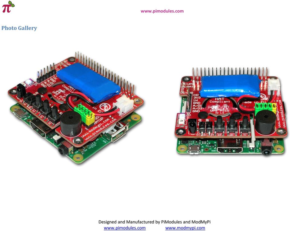
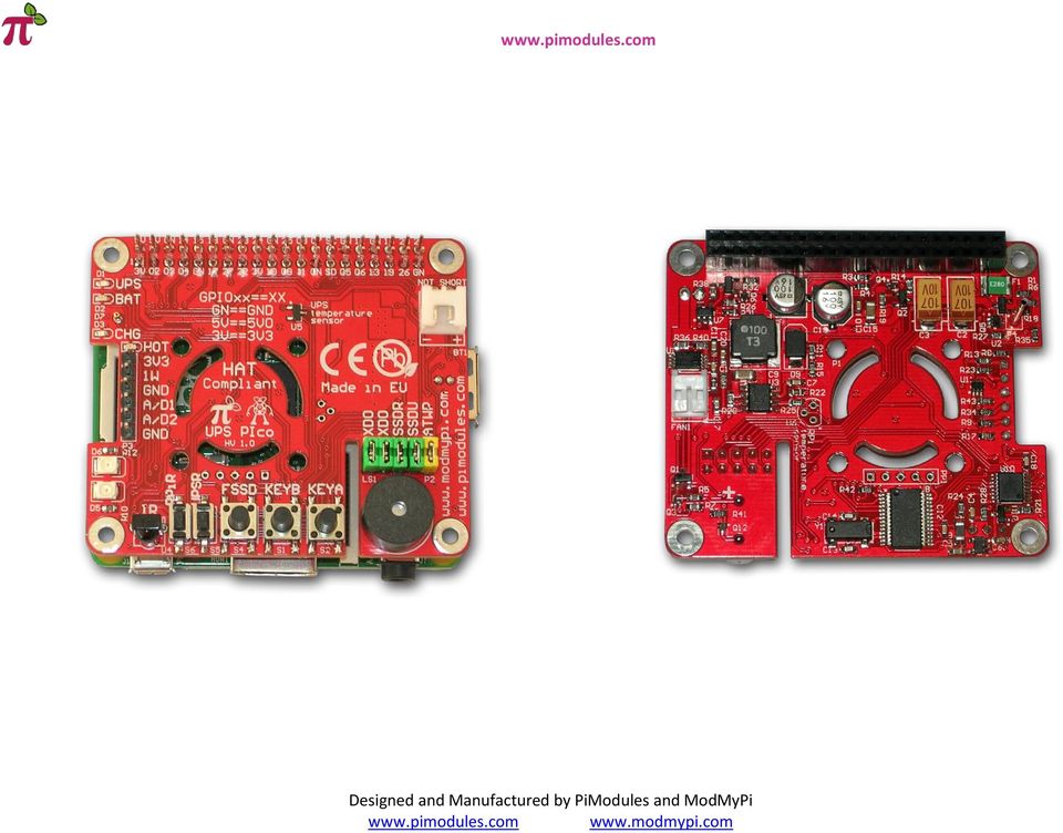
10 Photo Gallery
11

12
13

UPS PIco. to be used with. Raspberry Pi B+, A+, B, and A. HAT Compliant. Raspberry Pi is a trademark of the Raspberry Pi Foundation
 UPS PIco Uninterruptible Power Supply with Peripherals and I 2 C control Interface to be used with Raspberry Pi B+, A+, B, and A HAT Compliant Raspberry Pi is a trademark of the Raspberry Pi Foundation
UniPi technical documentation REV 1.1
 technical documentation REV 1.1 Contents Overview... 2 Description... 3 GPIO port map... 4 Power Requirements... 5 Connecting Raspberry Pi to UniPi... 5 Building blocks... 5 Relays... 5 Digital Inputs...
OPENUPS. 6-30V Intelligent Uninterruptible Power Supply. Installation Guide. Version 1.0f P/N OPENUPS-06
 OPENUPS 6-30V Intelligent Uninterruptible Power Supply Installation Guide Version 1.0f P/N OPENUPS-06 Before you start Please take a moment and read this manual before you install the OPENUPS. Often times,
Strato Pi Hardware Guide
 Strato Pi Hardware Guide October 2015 Revision 001 a professional expansion board for Raspberry Pi 2 Introduction 3 Features 4 Usage and connections 5 Hardware Installation 5 Strato Pi boards 5 Strato
FLYPORT Wi-Fi 802.11G
 FLYPORT Wi-Fi 802.11G System on module 802.11g WIFI - Infrastructure mode - softap mode - Ad hoc mode Microchip PIC 24F 16 bit processor Microchip MRF24WG0MA/MB - Native WiFi 802.11g transceiver - PCB
Web Site: www.parallax.com Forums: forums.parallax.com Sales: sales@parallax.com Technical: support@parallax.com
 Web Site: www.parallax.com Forums: forums.parallax.com Sales: sales@parallax.com Technical: support@parallax.com Office: (916) 624-8333 Fax: (916) 624-8003 Sales: (888) 512-1024 Tech Support: (888) 997-8267
SYSTEM 4C. C R H Electronics Design
 SYSTEM 4C C R H Electronics Design SYSTEM 4C All in one modular 4 axis CNC drive board By C R Harding Specifications Main PCB & Input PCB Available with up to 4 Axis X, Y, Z, A outputs. Independent 25
SYSTEM 45. C R H Electronics Design
 SYSTEM 45 C R H Electronics Design SYSTEM 45 All in one modular 4 axis CNC drive board By C R Harding Specifications Main PCB & Input PCB Available with up to 4 Axis X, Y, Z, & A outputs. Independent 25
Temperature & Humidity SMS Alert Controller
 Temperature & Humidity Alert Controller METERS 3 simple steps starting the unit: Insert the SIM card Plug in the sensors connectors Connect the AC power cord. Specifications: AC 90~260V Auto Select Internal
DKWF121 WF121-A 802.11 B/G/N MODULE EVALUATION BOARD
 DKWF121 WF121-A 802.11 B/G/N MODULE EVALUATION BOARD PRELIMINARY DATA SHEET Wednesday, 16 May 2012 Version 0.5 Copyright 2000-2012 Bluegiga Technologies All rights reserved. Bluegiga Technologies assumes
SNMP-1000 Intelligent SNMP/HTTP System Manager Features Introduction Web-enabled, No Driver Needed Powerful yet Easy to Use
 SNMP-1000 Intelligent SNMP/HTTP System Manager Features Monitors system fans, temperature, voltage, power supply, CPU fan, CPU temperature, Vcore, watchdog timer etc. Stand alone system monitoring, no
DCDC-USB. 6-34V 10A, Intelligent DC-DC converter with USB interface. Quick Installation Guide Version 1.0c P/N DCDC-USB
 DCDC-USB 6-34V 10A, Intelligent DC-DC converter with USB interface Quick Installation Guide Version 1.0c P/N DCDC-USB Introduction The DCDC-USB is a small yet powerful DC-DC power supply designed to power
EvB 5.1 v5 User s Guide
 EvB 5.1 v5 User s Guide Page 1 Contents Introduction... 4 The EvB 5.1 v5 kit... 5 Power supply...6 Programmer s connector...7 USB Port... 8 RS485 Port...9 LED's...10 Pushbuttons... 11 Potentiometers and
User s Manual of Board Microcontroller ET-MEGA2560-ADK ET-MEGA2560-ADK
 User s Manual of Board Microcontroller ET-MEGA2560-ADK ET-MEGA2560-ADK Because Arduino that is the development project on AVR MCU as Open Source has been published, it is popular and widespread shortly.
LIGHTNING. Key Features :: Cellular (UMTS/GSM) Sensors. Iridium SBD. Power. Physical Features
 Sensors. Iridium SBD. Power. Physical Features") LIGHTNING The LIGHTNING is a commercial, miniaturized, tri-mode tracking solution with processor, GPS, on-board storage, 2G/3G cellular module, Iridium satellite module, multiple sensors, multiple wired
LIGHTNING The LIGHTNING is a commercial, miniaturized, tri-mode tracking solution with processor, GPS, on-board storage, 2G/3G cellular module, Iridium satellite module, multiple sensors, multiple wired
HyperAccess Access Control System
 Control System We manufacture, an advanced PC based access control solution that will give you control over who has access to your building. With you can control access on hundreds of doors for up to 10,000
ECP240-32 & ECP240-32EX
 ECP240-32 & ECP240-32EX Hardware Manual 11Fl., 684-2, Deungchon 3-Dong, Gangseo-Gu, Seoul, Korea TEL: +82 2 2605 1486 FAX: +82 2 2605 1489 http://www.udptech.co.kr Contents 1. PRODUCT OVERVIEW...1 1.1
xpico Wi-Fi Embedded Device Server Evaluation Kit Quick Start Guide
 xpico Wi-Fi Embedded Device Server Evaluation Kit Quick Start Guide Part Number 900-685 Revision A June 2013 Copyright and Trademark Contacts 2013 Lantronix, Inc.. All rights reserved. No part of the contents
USER MANUAL V5.0 ST100
 GPS Vehicle Tracker USER MANUAL V5.0 ST100 Updated on 15 September 2009-1 - Contents 1 Product Overview 3 2 For Your Safety 3 3 ST100 Parameters 3 4 Getting Started 4 4.1 Hardware and Accessories 4 4.2
Designing Applications with Lithium-Ion Batteries
 Application Note Roland van Roy AN025 Sep 2014 Designing Applications with Lithium-Ion Batteries Contents 1. Introduction...1 2. Single Li-Ion Cell as Power Source...2 3. Battery Charging...6 4. Battery
BLE113 DEVELOPMENT KIT
 BLE113 DEVELOPMENT KIT QUICK START Thursday, 14 March 2013 Version 1.5 Copyright 2000-2013 Bluegiga Technologies Bluegiga Technologies reserves the right to alter the hardware, software, and/or specifications
Data Acquisition Module with I2C interface «I2C-FLEXEL» User s Guide
 Data Acquisition Module with I2C interface «I2C-FLEXEL» User s Guide Sensors LCD Real Time Clock/ Calendar DC Motors Buzzer LED dimming Relay control I2C-FLEXEL PS2 Keyboards Servo Motors IR Remote Control
KTA-223 Arduino Compatible Relay Controller
 8 Relay Outputs 5A 250VAC 4 Opto-Isolated Inputs 5-30VDC 3 Analog Inputs (10 bit) Connections via Pluggable Screw Terminals 0-5V or 0-20mA Analog Inputs, Jumper Selectable 5A Relay Switching Power Indicator
SMS GSM Alarm Messenger
 SMS GSM Alarm Messenger Data Logging Alarm Input Relay Output Voice Temperature Humidity Analog Input Capture and Send Data via SMS Report triggered alarm via SMS Output triggered via SMS Auto pick up
AC-115 Compact Networked Single Door Controller. Installation and User Manual
 AC-115 Compact Networked Single Controller Installation and User Manual December 2007 Table of Contents Table of Contents 1. Introduction...5 1.1 Key Features... 6 1.2 Technical Specifications... 7 2.
AUPS Series. User Manual MODEL: VESA Mount Intelligent UPS Module 12 V DC Input or 9 V ~ 36 V DC Input Network Remote Management Support
 AUPS Series Power Module MODEL: AUPS Series VESA Mount Intelligent UPS Module 12 V DC Input or 9 V ~ 36 V DC Input Network Remote Management Support User Manual Rev. 1.00 November, 2008 Page i Revision
Arduino Due Back. Warning: Unlike other Arduino boards, the Arduino Due board runs at 3.3V. The maximum. Overview
 R Arduino Due Arduino Due Front Arduino Due Back Overview The Arduino Due is a microcontroller board based on the Atmel SAM3X8E ARM Cortex-M3 CPU (datasheet). It is the first Arduino board based on a 32-bit
Disturbance Recoder SPCR 8C27. Product Guide
 Issued: April 1999 Status: Updated Version: C/26.04.2006 Data subject to change without notice Features Versatile digital disturbance recorder module for recording various phenomena in the electric power
NETWORK ENABLED EQUIPMENT MONITOR
 NETWORK ENABLED EQUIPMENT MONITOR Remotely Monitor Sensors over the Internet Connect Sensors to the Web to Remotely Monitor Equipment, Processes or Other Applications A Complete, Easy to Deploy, Stand-Alone
How To Use A Watt Saver On A Microcontroller (Watt Saver) On A Cell Phone Or Mp3 Player
 On A Cell Phone Or Mp3 Player") Watt Saver for a Cell Phone AC Adapter Reference Design Document Number: DRM130 Rev 1, 10/2013 2 Freescale Semiconductor, Inc. Contents Section number Title Page Chapter 1 Introduction 1.1 Overview...5
Watt Saver for a Cell Phone AC Adapter Reference Design Document Number: DRM130 Rev 1, 10/2013 2 Freescale Semiconductor, Inc. Contents Section number Title Page Chapter 1 Introduction 1.1 Overview...5
The modular concept of the MPA-3 system is designed to enable easy accommodation to a huge variety of experimental requirements.
 HARDWARE DESCRIPTION The modular concept of the MPA-3 system is designed to enable easy accommodation to a huge variety of experimental requirements. BASE MODULE GO LINE Digital I/O 8 Analog Out AUX 1
RC2200DK Demonstration Kit User Manual
 Demonstration Kit User Manual Table of contents TABLE OF CONTENTS... 1 QUICK INTRODUCTION... 2 INTRODUCTION... 3 DEMONSTRATION BOARD... 4 POWER SUPPLY SECTION... 5 RS-232 INTERFACE... 6 CONNECTORS... 7
EMBEDDED ACCESS CONTROL Hardware Installation Guide
 EMBEDDED ACCESS CONTROL Hardware Installation Guide Lenel goentry Hardware Installation Guide, product version 1.00. This guide is item number DOC- ENHW-ENU, revision 1.003, April 2009 Copyright 2009 Lenel
USBSPYDER08 Discovery Kit for Freescale MC9RS08KA, MC9S08QD and MC9S08QG Microcontrollers User s Manual
 USBSPYDER08 Discovery Kit for Freescale MC9RS08KA, MC9S08QD and MC9S08QG Microcontrollers User s Manual Copyright 2007 SofTec Microsystems DC01197 We want your feedback! SofTec Microsystems is always on
RN-WIFLY-EVAL-UM. WiFly Evaluation Kit. 2012 Roving Networks. All rights reserved. RN-WIFLY-EVAL-UM Version 1.32r 10/9/2012 USER MANUAL
 WiFly Evaluation Kit 2012 Roving Networks. All rights reserved. Version 1.32r 10/9/2012 USER MANUAL OVERVIEW This document describes the hardware and software setup for Roving Networks evaluation kits,
User Manual. ATX12V / EPS12V Power Supply TG-I460R (460W+460W) TG-I550R (550W+550W) Switching Power Supply User Manual
 TG-I550R (550W+550W) Switching Power Supply User Manual") ATX12V / EPS12V Power Supply TG-I460R (460W+460W) TG-I550R (550W+550W) User Manual Table of Contents 1 Introduction 2 General specification 3 Installation 4 Pin assignment & function of connectors 5 Drawing
ATX12V / EPS12V Power Supply TG-I460R (460W+460W) TG-I550R (550W+550W) User Manual Table of Contents 1 Introduction 2 General specification 3 Installation 4 Pin assignment & function of connectors 5 Drawing
DS1104 R&D Controller Board
 DS1104 R&D Controller Board Cost-effective system for controller development Highlights Single-board system with real-time hardware and comprehensive I/O Cost-effective PCI hardware for use in PCs Application
CM705B - Universal Expander Module CM707B - Plug On Zone Expander Security Systems
 CM705B - Universal Expander Module CM707B - Plug On Zone Expander Security Systems EN Security System CM705B CM705B - Universal Expander Module The CM705B universal expander provides a cost effective way
Modular I/O system Rugged Modular I/O System Solutions EN-50155 certified for railway applications
 The systems and devices of the MODULAR I/O family are the Tecnint HTE solutions for industrial and technological application of automation, acquisition and management that require particularly robustness
Designing VM2 Application Boards
 Designing VM2 Application Boards This document lists some things to consider when designing a custom application board for the VM2 embedded controller. It is intended to complement the VM2 Datasheet. A
In regard to calculating system power requirements, refer to DBK Basics located near the front of this manual.
 DBK42 16-Slot 5B Signal Conditioning Module Overview 1 Hardware Setup 2 DBK42 Connection 2 DBK42 Configuration 2 5B Module Connection 2 Power Considerations 2 Terminal Block Connections 3 DaqBoard/2000
Alarm over IP. IRIS Touch Home Installation Manual. Version 1.0 ENGLISH. Now certified and compliant with EN50131, EN50136 Security Grade 4 ATS6
 Alarm over IP IRIS Touch Home Installation Manual Version 1.0 ENGLISH Now certified and compliant with EN50131, EN50136 Security Grade 4 ATS6 1. Introduction No more bulky batteries, just one sleek unit
SOLARCARE SERIES PRODUCT AND APPLICATION GUIDE
 SOLARCARE SERIES PRODUCT AND APPLICATION GUIDE for solar energy management LEATEC Delivering Solutions for Energy Management SOLAR ENERGY DATA CENTER BUILDING 4 to8 String Monitoring with 0.% Accuracy
WICE-SPI Hardware Operation Manual
 Contents 1.Hardware Instruction...1 2. Pin Definition Of WICE-SPI Connector...2 3. Peripheral Circuit Arrangements...3 4. On-Board Programming...4 5. Off-Line Programming...8 1.Hardware Instruction 1.WICE-SPI
TCP/IP MODULE CA-ETHR-A INSTALLATION MANUAL
 TCP/IP MODULE CA-ETHR-A INSTALLATION MANUAL w w w. c d v g r o u p. c o m CA-ETHR-A: TCP/IP Module Installation Manual Page Table of Contents Introduction...5 Hardware Components... 6 Technical Specifications...
RUNNING A BUSINESS IS FUN, BUT IT S ALSO HARD WORK
 RUNNING A BUSINESS IS FUN, BUT IT S ALSO HARD WORK Click to edit Master text styles Click to edit Master text styles Second level Third level 2 MODERN BUSINESS IS ALL ABOUT DATA & CONNECTIVITY Every enterprise
xpico Wi-Fi Embedded Device Server Evaluation Board Quick Start Guide
 xpico Wi-Fi Embedded Device Server Evaluation Board Quick Start Guide Part Number 900-685 Revision B December 2014 Copyright and Trademark Contacts 2014 Lantronix, Inc.. All rights reserved. No part of
Uninterruptible Power Supply
 96-01101 / rev. 2e / 2-2-12 Uninterruptible Power Supply EXCEPTIONAL SUPPORT & PROTECTION Uninterruptible Power Supply with Energy Saver design that is optimized to address the needs of A/V systems Features
MN1010 Evaluation Kit v3 User Guide
 1 Evaluation Kit Introduction The MN1010 Evaluation Kit is designed to allow the user to quickly evaluate the Micro Modular Technologies MN1010 GPS receiver module. This kit can be used in either a laboratory
SmartPro 120V 2.2kVA 1.92kW Line-Interactive Sine Wave UPS, SNMP, Webcard option, 2U Rack/Tower, LCD, USB, DB9 Serial
 SmartPro 120V 2.2kVA 1.92kW Line-Interactive Sine Wave UPS, SNMP, Webcard option, 2U Rack/Tower, LCD, USB, DB9 Serial MODEL NUMBER: SMART2200RM2U Highlights 2.2kVA / 2200VA / 1920W line interactive 2U
User and installation manual
 User and installation manual aquaero 5 The information contained in this manual is subject to change without prior notice. All rights reserved. Current as of April 2011 ENGLISH: PAGE 1 DEUTSCH: SEITE 13
M3-ATX-HV. 6-34V Intelligent ATX Power Supply. Installation Guide Version 1.0c P/N M3-ATX-HV-01
 M3-ATX-HV 6-34V Intelligent ATX Power Supply Installation Guide Version 1.0c P/N M3-ATX-HV-01 Before you start Please take a moment and read this manual before you install the M3-ATX-HV in your vehicle.
Embedded Systems on ARM Cortex-M3 (4weeks/45hrs)
") Embedded Systems on ARM Cortex-M3 (4weeks/45hrs) Course & Kit Contents LEARN HOW TO: Use of Keil Real View for ARM Use ARM Cortex-M3 MCU for professional embedded application development Understanding
Embedded Systems on ARM Cortex-M3 (4weeks/45hrs) Course & Kit Contents LEARN HOW TO: Use of Keil Real View for ARM Use ARM Cortex-M3 MCU for professional embedded application development Understanding
Smart relays Zelio Logic Step into an intuitive world!
 Smart relays Zelio Logic Step into an intuitive world! Simply Smart! Leveraging ingenuity and intelligence for ease of use Simply select your Zelio Logic! Designed for the management of simple automation
HARDWARE MANUAL. BrightSign HD120, HD220, HD1020. BrightSign, LLC. 16795 Lark Ave., Suite 200 Los Gatos, CA 95032 408-852-9263 www.brightsign.
 HARDWARE MANUAL BrightSign HD120, HD220, HD1020 BrightSign, LLC. 16795 Lark Ave., Suite 200 Los Gatos, CA 95032 408-852-9263 www.brightsign.biz TABLE OF CONTENTS OVERVIEW... 1 Block Diagram... 2 Ports...
revolution Contents: Introduction Power 28-pin Project Board with input/output cables
 28-PIN IN IN PROJECT BOARD Contents: AXE020 28-pin Project Board with input/output cables Introduction The 28-pin project board is designed to allow rapid prototyping with 28-pin PICAXE microcontrollers.
Optimize your simple machines... Modicon M218 Selection Guide
 Optimize your simple machines... Modicon M218 Selection Guide Compact Solution for Simple Machines Optimized Logic Controller Modicon M218 With intelligent software platform, specialized functional s,
AN588 ENERGY HARVESTING REFERENCE DESIGN USER S GUIDE. 1. Kit Contents. 2. Introduction. Figure 1. Energy Harvesting Sensor Node
 ENERGY HARVESTING REFERENCE DESIGN USER S GUIDE 1. Kit Contents The RF to USB Reference Design contains the following items: Si1012 Energy Harvesting Wireless Sensor Node EZRadioPRO USB Dongle ToolStick
AUPS-C20. User Manual MODEL: VESA Mount Intelligent UPS Module, 9 V ~ 28 V DC Input, 100 W Power Output, Network Remote Management Support
 AUPS-C20 UPS Module IEI Technology Corp. MODEL: AUPS-C20 VESA Mount Intelligent UPS Module, 9 V ~ 28 V DC Input, 100 W Power Output, Network Remote Management Support User Manual Page i Rev. 1.01 30 October,
OmniVS Series 1500VA Line-Interactive Tower 120V UPS with USB port
 OmniVS Series 1500VA Line-Interactive Tower 120V UPS with USB port MODEL NUMBER: OMNIVS1500 Highlights 1500VA / 1.5kVA tower 120V line-interactive UPS Corrects brownouts and overvoltages from 75 to 147V
Current Monitoring Kit QUICK START GUIDE
 Current Monitoring Kit QUICK START GUIDE Pico Technology EL040 Current Monitoring Kit Quick Start Guide CONTENTS 1 Introduction... 1 2 Kit contents... 3 3 Installation... 3 3.1 Connecting the system together...
ABB Drives. User s Manual HTL Encoder Interface FEN-31
 ABB Drives User s Manual HTL Encoder Interface FEN-31 HTL Encoder Interface FEN-31 User s Manual 3AUA0000031044 Rev B EN EFFECTIVE: 2010-04-06 2010 ABB Oy. All Rights Reserved. 5 Safety instructions
RN-XV-RD2 Evaluation Board
 RN-XV-RD2 Evaluation Board 2012 Roving Networks. All rights reserved. -1.01Version 1.0 9/28/2012 USER MANUAL OVERVIEW This document describes the hardware and software setup for Roving Networks RN-XV-RD2
Nuvoton Nu-Link Debug Adapter User Manual
 Nuvoton Nu-Link Debug Adapter User Manual The information described in this document is the exclusive intellectual property of Nuvoton Technology Corporation and shall not be reproduced without permission
FIREDEX 2200. Conventional Fire Panels
 68 Flexible, high specification system Choice of 1, 2, 4 or 8 zones Simple one-shot auto-reset user test facility Approved to EN54 Maintenance free poly switch circuit protection, with auto reset Class
SVC400P/SVC800P. 4/8 Camera Live Tracking Vehicle DVR Installation Manual. Version 1.0
 SVC400P/SVC800P 4/8 Camera Live Tracking Vehicle DVR Installation Manual Version 1.0 1. MAIN FEATURES... 2 2. PRODUCT OVERVIEW... 2 3. DIMENSIONS... 4 4. PACKAGE CONTENTS... 5 5. MOUNTING AND ENVORNMENTAL
User Manual. AS-Interface Programmer
 AS-Interface Programmer Notice: RESTRICTIONS THE ZMD AS-INTERFACE PROGRAMMER HARDWARE AND ZMD AS-INTERFACE PROGRAMMER SOFTWARE IS DESIGNED FOR IC EVALUATION, LABORATORY SETUP AND MODULE DEVELOPMENT ONLY.
M2-ATX. 6-24V Intelligent Automotive ATX Power Supply. Installation Guide Version 1.4 (firmware v1.5, 10/15/2009) P/N M2-ATX-01
 P/N M2-ATX-01") M2-ATX 6-24V Intelligent Automotive ATX Power Supply Installation Guide Version 1.4 (firmware v1.5, 10/15/2009) P/N M2-ATX-01 Before you start Please take a moment and read this manual before you install
M2-ATX 6-24V Intelligent Automotive ATX Power Supply Installation Guide Version 1.4 (firmware v1.5, 10/15/2009) P/N M2-ATX-01 Before you start Please take a moment and read this manual before you install
SBC8600B Single Board Computer
 SBC8600B Single Board Computer 720MHz TI s Sitara AM3359 ARM Cortex-A8 Microprocessor Onboard 512MByte DDR3 SDRAM and 512MByte NAND Flash UARTs, 2*USB Host and 1*OTG, 2*Ethernet, CAN, RS485, LCD/TSP, Audio,
SKY LIGHT INTERSECTION SYSTEM
 SKY LIGHT INTERSECTION SYSTEM Sky Light Interface Card 868 NABLA QUADRO S.r.l. Via Giacomo Peroni 442 00131 Roma March 2015 Pagina 1 di 5 Nabla Quadro S.r.l. Sky Light Interface Card 868 General specification
M2M/IoT Solutions. www.contec.com
 M2M/IoT Solutions www.contec.com M2M/IoT Solutions TM Hardware Highly Reliable M2M Controllers for Various Solutions M2M Controllers Compact design available on DIN rails Low-power design using a CPU tailored
AN00140-003: Using Wago CANOpen IO
 AN00140-003: Using Wago CANOpen IO Overview Baldor now offers WAGO Modular IO Systems for use with Mint Motion Controllers using the CANOpen field bus interface. The WAGO units provide a very flexible
Installation and Operation Manual Back-UPS BX800CI-AS/BX1100CI-AS
 + Installation and Operation Manual Back-UPS BX800CI-AS/BX1100CI-AS Inventory Safety and General Information bu001c This unit is intended for indoor use only. Do not operate this unit in direct sunlight,
WIZ-Embedded WebServer User s Manual (Ver. 1.0)
") [텍스트 입력] WIZ-Embedded WebServer User s Manual (Ver. 1.0) 2007 WIZnet Inc. All Rights Reserved. For more information, visit our website at www.wiznet.co.kr Document History Information Revision Data Description
[텍스트 입력] WIZ-Embedded WebServer User s Manual (Ver. 1.0) 2007 WIZnet Inc. All Rights Reserved. For more information, visit our website at www.wiznet.co.kr Document History Information Revision Data Description
Current Monitoring Kit
 Current Monitoring Kit QUICK START GUIDE DO090-6 CONTENTS Issues: 1) 2.10.02 WP A4 format 2) 2.10.02 Added safety warning 3) 17.3.06 Word A5 format. S1: Removed relay modules. S2: Added MI010. S4.1: added
Arduino ADK Back. For information on using the board with the Android OS, see Google's ADK documentation.
 Arduino ADK Arduino ADK R3 Front Arduino ADK R3 Back Arduino ADK Front Arduino ADK Back Overview The Arduino ADK is a microcontroller board based on the ATmega2560 (datasheet). It has a USB host interface
Daker DK 1, 2, 3 kva. Manuel d installation Installation manual. Part. LE05334AC-07/13-01 GF
 Daker DK 1, 2, 3 kva Manuel d installation Installation manual Part. LE05334AC-07/13-01 GF Daker DK 1, 2, 3 kva Index 1 Introduction 24 2 Conditions of use 24 3 LCD Panel 25 4 Installation 28 5 UPS communicator
FM4100 USER MANUAL V1.4
 FM4100 USER MANUAL V1.4 Table of Contents ATTENTION!... 2 INSTRUCTIONS OF SAFETY... 3 LEGAL NOTICE... 4 Short description...5 1.1 About the document... 5 1.2 Acronyms... 5 1.3 Mounting guidelines... 5
SBC6245 Single Board Computer
 SBC6245 Single Board Computer 400MHz Atmel AT91SAM9G45 ARM 926EJ-STM Microcontroller On Board 128MB Nand Flash plus 128MB DDR2 SDRAM RS232, RS485, Ethernet, USB Host, LCD, Touch Screen, RTC, Supports for
Building the Portable Power Supply for Kinect V2 Camera
 Building the Portable Power Supply for Kinect V2 Camera Kexiang Qian April 3, 2015 Executive Summary This paper is aim to introduce how to customize a portable power source for the Xbox one Kinect camera
This Datasheet for the IC697CPM790. GMR Redundancy CPU, 486, 2K Triplex (voted) I/O. http://www.cimtecautomation.com/parts/p-14778-ic697cpm790.
 I/O. http://www.cimtecautomation.com/parts/p-14778-ic697cpm790.") his Datasheet for the GMR Redundancy CPU, 486, 2K riplex (voted) I/O. http://www.cimtecautomation.com/parts/p-14778-ic697cpm790.aspx Provides the wiring diagrams and installation guidelines for this GE
his Datasheet for the GMR Redundancy CPU, 486, 2K riplex (voted) I/O. http://www.cimtecautomation.com/parts/p-14778-ic697cpm790.aspx Provides the wiring diagrams and installation guidelines for this GE
ACR880 GPRS Portable Smart Card Terminal
 ACR880 GPRS Portable Smart Card Terminal Technical Specifications Subject to change without prior notice Table of Contents 1.0. Introduction... 3 2.0. Features... 4 3.0. Supported Card Types... 5 3.1.
Embedded Display Module EDM6070
 Embedded Display Module EDM6070 Atmel AT91SAM9X35 Based Single Board Computer BY Product Overview Version 1.0 Dated: 3 rd Dec 2013 Table of Contents Product Overview... 2 Introduction... 2 Kit Contents...
Quick Start Guide for High Voltage Solar Inverter DC-AC Board EVM. Version 1.3
 Quick Start Guide for High Voltage Solar Inverter DC-AC Board EVM Version 1.3 Introduction This document talks about the quick start principles for the high voltage solar inverter DC-AC board. From this
Bluetooth + USB 16 Servo Controller [RKI-1005 & RKI-1205]
![Bluetooth + USB 16 Servo Controller [RKI-1005 & RKI-1205]](/thumbs/40/21161302.jpg "Bluetooth + USB 16 Servo Controller [RKI-1005 & RKI-1205]") Bluetooth + USB 16 Servo Controller [RKI-1005 & RKI-1205] Users Manual Robokits India info@robokits.co.in http://www.robokitsworld.com Page 1 Bluetooth + USB 16 Servo Controller is used to control up to
Bluetooth + USB 16 Servo Controller [RKI-1005 & RKI-1205] Users Manual Robokits India info@robokits.co.in http://www.robokitsworld.com Page 1 Bluetooth + USB 16 Servo Controller is used to control up to
The following is a summary of the key features of the ARM Injector:
 Intended Use The ARM Injector is an indispensable tool for engineers who work with JTAG enabled target systems based on an ARM processor core with Debug and EmbeddedICE capability. The ARM Injector provides
A-307. Mobile Data Terminal. Android OS Platform Datasheet
 A-307 Mobile Data Terminal Android OS Platform Datasheet Revision 1.1 July, 2013 Introduction A-307 Platform Overview Introduction A-307 Platform Overview The A-307 provides Original Equipment Manufacturers
GSM Voice Auto Dialer & SMS Sender JC-999
 GSM Voice Auto Dialer & SMS Sender JC-999 Main features: () Large LCD display,integrated integrated keypad, human-friendly programming; (2) Support 2 alarm receiving numbers; (3) Triggering means: N.C
Advanced Data Capture and Control Systems
 Advanced Data Capture and Control Systems Tronisoft Limited Email: sales@tronisoft.com Web: www.tronisoft.com RS232 To 3.3V TTL User Guide RS232 to 3.3V TTL Signal Converter Modules P/N: 9651 Document
PRT3 Printer Module: ASCII Protocol Programming Instructions
 PRT3 Printer Module: ASCII Protocol Programming Instructions We hope this product performs to your complete satisfaction. Should you have any questions or comments, please visit www.paradox.com and send
Analog Devices Welcomes Hittite Microwave Corporation NO CONTENT ON THE ATTACHED DOCUMENT HAS CHANGED
 Analog Devices Welcomes Hittite Microwave Corporation NO CONTENT ON THE ATTACHED DOCUMENT HAS CHANGED www.analog.com www.hittite.com THIS PAGE INTENTIONALLY LEFT BLANK PLL & PLL with Integrated VCO Evaluation
NGSS Data Consolidator (DC)
") NGSS Data Consolidator (DC) The Data Consolidator (DC) facilitates system configuration, monitors network status, and supervises long-term data storage and remote data transmission. The DC consists of
NGSS Data Consolidator (DC) The Data Consolidator (DC) facilitates system configuration, monitors network status, and supervises long-term data storage and remote data transmission. The DC consists of
Quick Start Guide. The Raspberry Pi Single Board Computer. Source: Raspberry Pi & Wiki
 Quick Start Guide The Raspberry Pi Single Board Computer Source: Raspberry Pi & Wiki Chapter 1: RPi Hardware Basic Setup Typical Hardware You Will Need While the RPi can be used without any additional
Radio sensor powered by a mini solar cell the EnOcean STM 110 now functions with even less light
 Radio sensor powered by a mini solar cell the EnOcean STM 110 now functions with even less light In this issue, we would like to present the EnOcean radio sensor module STM 110 in more detail. The module
Electronic Control Devices The European Product Catalogue 2007
 FX14 Field Controller (1/4) FX14 Field Controller The FX14 is an equipment field controller in the Facility Explorer range of products. The controller is designed specifically for commercial Heating, Ventilating,
Product Information S N O. Portable VIP protection CCTV & Alarm System 2
 Product Information S N O Portable VIP protection CCTV & Alarm System 2 G O V E R N M E N T A L S E C U R I T Y S O L U T I VIP KIT Rapid Deployment VIP Protection Kit The VIP KIT has been designed to
MN3310 Evaluation Kit v1 User Guide
 1 Evaluation Kit Introduction The MN3310 Evaluation Kit is designed to allow the user to quickly evaluate the Micro Modular Technologies MN3310 GPS receiver module. The evaluation kit can be used in either
Smart Thermostat page 1
 Smart Thermostat page 1 3. APPROACH In today s home appliances market, automation is becoming the norm and Smart Thermostat is a typical automation appliance able to be applied easily at home. With Smart
EZmoto V2. Product description Rev. 6 10/01/2014. EZmoto V2 Product description Rev.6 10/01/2014
 EZmoto V2 Product description Rev. 6 10/01/2014 1 Contents 1. Overview... 3 2. Hardware Interface Description... 3 2.1 Main features of the EZmoto... 3 2.2 Hardware block diagram... 4 2.3 Internal Hardware
SmartPro 230V 3kVA 2.25kW Line-Interactive UPS, Extended Run, SNMP, Webcard, Tower, USB, DB9 Serial
 SmartPro 230V 3kVA 2.25kW Line-Interactive UPS, Extended Run, SNMP, Webcard, Tower, USB, DB9 Serial MODEL NUMBER: SMARTINT3000VS Highlights 3kVA / 3000VA / 2250W line interactive tower UPS system 230V