Optical Communication Networks. Client of the optical layer
|
|
|
- Joshua Parks
- 10 years ago
- Views:
Transcription
1 Optical Communication Networks Client of the optical layer Optical Communicaton Systems A.A. 2012/2013


2 Client of the optical layer (1) Client of optical layer Sonet/SDH ATM IP MPLS Storage-Area Networks Gigabit Ethernet RPR


3 Client of the optical layer (2) Networks that use optical fiber as transmission medium The optical layer provides lightpaths to clients Equivalent to physical point-to-point links Client layers process data in electrical format, by aggregating fluxes at low bit rate Fixed or statistical multiplexing Main client layers for backbone: Sonet/SDH, IP, ATM IP/ATM over Sonet, or IP/ATM over optical Main client layers for MAN and SAN Gigabit Ethernet, RPR, Fibre Channel

4 Client of the optical layer Client of optical layer Sonet/SDH ATM IP MPLS Storage-Area Networks Gigabit Ethernet RPR

5 Sonet/SDH vs. PDH (1) Sonet (Synchronous Optical Network) Standard for multiplexing and high bit rate data trasmissions in US network infrastructures SDH (Synchronous Digital Hierarchy) Analogous standard adopted in Europe, Japan and for submarine links Before Sonet and SDH PDH (Plesiochronous Digital Hierarchy), 1960 In the USA, digital asynchronous hierarchy Objective: multiplexing of voice signals Characteristics of voice signals Bandwidth: 4 khz Sampling: 8 khz (Shannon) Quantisation: 8 bits per sample Total bitrate: 64 kbit/s (PCM) Widely adopted standard
, 1960 In the USA, digital asynchronous hierarchy Objective: multiplexing of voice signals Characteristics of voice signals")
 PCM 64 kbit/s as basic signal Higher bitrate fluxes are multiples of 64 kbit/s Different standards in USA, Europe, Japan USA PCM 64 kbit/s: signal DS0 (Digital Signal 0)")
6 Sonet/SDH vs. PDH (2) PCM 64 kbit/s as basic signal Higher bitrate fluxes are multiples of 64 kbit/s Different standards in USA, Europe, Japan USA PCM 64 kbit/s: signal DS0 (Digital Signal 0) Signals DS1 (1.544 Mbps), DS3 ( Mbps) Associated transmission channels are called T1, T3 Europe Basic unit signal DS0 Formats are defined as E0, E1, E2, E3, E4
 Signals DS1 (1.544 Mbps), DS3 (44.")
7 Sonet/SDH vs. PDH (3) Previously defined bitrates are still widely used by network operators for renting links to clients However PDH had big problems : carriers look for new standards Standard Sonet/SDH Solves many of PDH problems Advantages of Sonet/SDH with respect to PDH 1) Simplification of multiplexing process Plesiochronous signals (PDH): signals characterised by a nominal rate that varies between well-defined limits Asynchronous multiplexing: each terminal has its own clock There is a unique specified nominal clock but There are significant differences in real values E.g. DS3 signals, clock variations of 20 ppm (realistic value) bitrate differences of 1.8 kbit/s!
: signals characterised by a nominal rate that varies between well-defined limits Asynchronous multiplexing: each terminal has its own clock There is a unique")
8 Sonet/SDH vs. PDH (4) Necessity of bit stuffing When multiplexing low bitrare fluxes, extra bits are added to take into account of misaligned clocks Defined bitrates are not multiples of DS0, but slightly higher E.g., DS1 = Mbps, but 24 x 64 kbit/s = 1.5 Mbps Difficulties in extracting low bitrate fluxes from high bitrate flux Necessity to fully demultiplex the flux Use of multiplexer/demultiplexer stacks Weak reliability, costly, much electronics required Sonet/SDH è synchronous All clocks are synchronised to a master clock Bitrates are multiples of DS0, bit stuffing not necessary Reduction of mux/demux cost A low bitrate flux can be extracted at once from Sonet/SDH flux! The design of Sonet ADM is very simple

9 Sonet/SDH vs. PDH (5) E.g. Extraction of DS1 signal from DS4 signal (a) Demultiplexing in PDH case (b) Demultiplexing in Sonet/SDH case
 Demultiplexing in")
10 Sonet/SDH vs. PDH (6) 2) Management Simplified network management Monitoring of performances Identification of the type of traffic and connection Identification of faults A channel is dedicated to the transmission of informations for network management All above is a property of Sonet/SDH, PDH is not suitable 3) Interoperability PDH did not define a standard transmission format Difficult to connect devices from different makers Different coding, optical interfaces Sonet/SDH define standard optical interfaces Interoperability among devices from different makers 4) Network reliability Sonet/SDH: provide topologies, protocols and protection techniques for highly reliable networks (restoration in 60 ms) PDH: restoration times from seconds to minutes
")
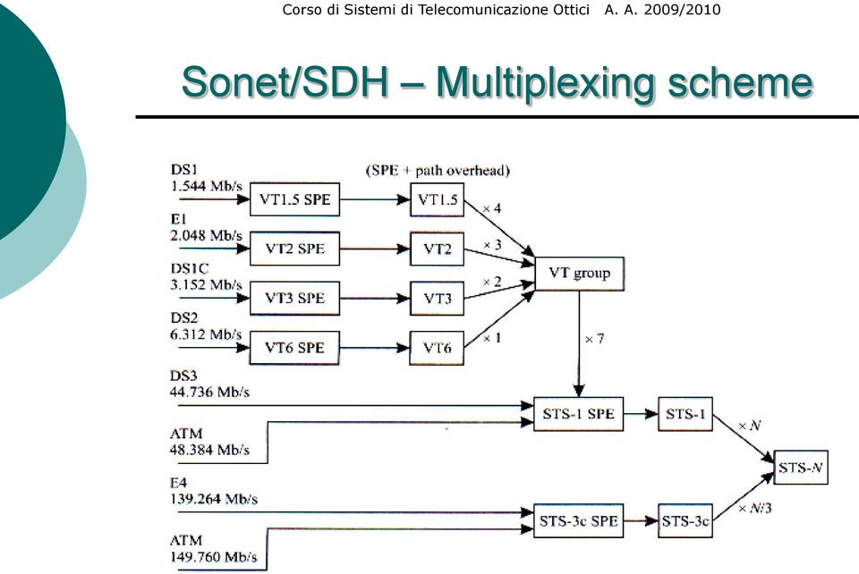
11 Sonet/SDH Multiplexing (1) Complex multiplexing system Implementation with VLSI integrated circuits Sonet and SDH are similar, but terminology is different Let us explain Sonet, and point out differences in SDH Sonet: basic bitrate Mbps Synchronous Transport Signal level-1 (STS-1) STS-N: signal with N times higher bitrate Interleaving of N STS-1 bytes, frame by frame
 STS-N: signal with N times higher")
12 Sonet/SDH Multiplexing (2) Clocks of all signals are synchronised Bit stuffing not necessary Low bitrate fluxes can be extracted without total demux STS is an electrical signal Such signal often exists in Sonet devices only Optical interface with other devices Transmitted optical signal is STS with scrambling To eliminate long sequences of 1 s and 0 s The receiver applies descrambling and demodulates To the STS-N electrical signal, it corresponds the OC-N optical interface (Optical Carrier-N) E.g., to STS-3 corresponds OC-3, to STS-12 OC-12 SDH: basic bitrate 155 Mbps Synchronous Transport Module-1 (STM-1) The same term is used both for electrical and optical signals
 E.g.")
13 Sonet/SDH Multiplexing (3) Sonet Bitrate chosen for the transmission of most common asynchronous signals (DS1 and DS3) SDH Bitrate chosen for the transmission of most common PDH signals (E1, E3, E4) Strutture of Sonet frame Transport Overhead Payload Content of Synchronous Payload Envelope (SPE) SPE contains the Path Overhead bytes, inserted at the source and extracted at destination only E.g. path trace bytes, identify the SPE and are used to verify the connection


 indicates the starting byte")
14 Sonet/SDH Multiplexing (4) Use of pointers to indicate the payload within the frame SPE does not have a fixed starting point in the frame All clocks derived from a single source Small transient frequency variations are possible Small phase differences between the input and output signals Solution: one allows the payload to shift back and forward in the frame No bit stuffing or buffering, but electronics to manage the pointers Pointer in the Transport Overhead (Line Overhead) indicates the starting byte in the SPE
 indicates the starting byte")
 Use of virtual tributaries (VT) Each VT designed with sufficient bandwidth to transmit a different payload Sonet, 4 VT of different dimensions VT1.5: 1.")
15 Sonet/SDH Virtual tributaries (1) Necessary to map in frame STS-1 non Sonet fluxes at lower bitrate (e.g. DS1) Use of virtual tributaries (VT) Each VT designed with sufficient bandwidth to transmit a different payload Sonet, 4 VT of different dimensions VT1.5: 1.5 Mbps, DS1 signals VT2: 2 Mbps, E1 signals VT3: 3 Mbps, DS1C signals VT6: 6 Mbps, DS2 signals VT composed by VT SPE: VT Synchronous Payload Envelope VT Path Overhead and VT pointer

16 Sonet/SDH Virtual tributaries (2) VT group Aggregation of VT in groups, 4 possibilities 4 x VT1.5 3 x VT2 2 x VT3 1 x VT6 Sonet STS-1 SPE Interleaving of 7 VT groups and Path Overhead byte VT SPE may fluctuate inside the STS-1 SPE VT pointer (2 bytes) indicates the beginning of VT SPE

17 Sonet/SDH Virtual tributaries (3) Necessity to map high bitrate non-sonet fluxes in STS- 1 SPE for Sonet transport Fluxes from IP router or ATM switch transported with Sonet STS-Nc (c means concatenated ) Signal locked payload, that is it cannot be demultiplexed in low bitrate fluxes E.g., ATM 150 Mbps signal transmitted on Sonet Use STS-3c signal Mapping defined for many classes of signals ATM, IP, FDDI SDH: same reasoning, different terminology VC (virtual containers) instead of VT VC-11 (DS1), VC-12 (E1), VC-2 (E2), VC-3 (E3 e DS3), VC-4 (E4) VC-11, VC-12 and VC-2 multiplexed in VC-3 e VC-4 VC-3 e VC-4 multiplexed to form STM-1

18 Sonet/SDH Multiplexing scheme
19 Sonet/SDH STS-1 Frame (1) STS-1 Frame Duration 125 μs (8000 frames/s) In analogy with 8 khz of PCM signal Indipendent of Sonet signal bitrate 9 rows by 90 columns, each cell is 1 byte Overall 810 bytes, payload + overhead (9 x 90 x 8) bit/frame x 8000 frames/s = Mbps Bytes are transmitted row after row, from left to right, the MSB (most significant bit) is transmitted first First 3 columns for the Transport Overhead Overhead Section Overhead Line Other columns for STS-1 SPE The first column contains the Path Overhead
 is transmitted first First 3")
20 Sonet/SDH STS-1 Frame (2) Structure of the STS-1 frame


21 Sonet/SDH STS-N Frame (3) STS-N Frame Interleaving of the N STS-1 frame bytes Transport Overhead in first 3N columns N sets of overhead bytes, 1 for each STS-1 Alignment with the frame Payload in remaining 87N columns Frame alignment not necessary STS-Nc Frame Similar to STS-N, but the payload in the 87N columns cannot be demultiplexed by Sonet STS payload pointer indicates the concatenated frame 1 set of overhead bytes only Payload remains unchanged from sender to receiver
22 Sonet/SDH STS-N Frame (4) Structure of STS-N frame
23 Sonet/SDH Layers (1) Sonet layer divided in 4 sublayers Path layer Line layer Section layer Physical layer Each layer, except for the physical one, adds overhead Overhead bytes added when introducing the layer and removed when the layer is finished Meaning of this overhead is explained later on Sonet (SDH) Path layer: end-to-end connection between nodes, only visible at link extremities Path overhead inserted by sender, extracted by receiver
24 Sonet/SDH Layers (2) Line layer (multiplex section layer): multiplexes a certain number of connections at path level on a single link between 2 nodes Line overhead is processed at each intermediate node with TM (Terminal Mux) or ADM (Add-Drop Mux) Responsable of protection switching (faults) Section layer (regenerator-section layer): corresponds to each span between regenerators Physical layer: trasmission of bits on fiber

25 Sonet/SDH Overhead Provide advanced management functions Particularly useful for carriers Enable understanding of connection functioning rather than exact localization and format Section and Line Overhead are important for the optical layer Many bytes are controlled by the optical layer Other bytes are still undefined Suitable for transporting the optical layer overhead In Sonet/SDH we have 3 types of overhead Section Overhead Line Overhead Path Overhead
26 Sonet/SDH Section Overhead (1) Framing (A1/A2) Used by network elements to allocate the frame, in each STS-1 inside a STS-N Section Trace (J0)/Section Growth (Z0) J0 in the first STS-1 inside a STS-N, identification byte to monitor the connection between nodes Z0 in the remaining STS-1, not yet used Section BIP-8 (B1) In the first STS-1 inside a STS-N BER monitoring between adjacent nodes Orderwire (E1) In first STS-1 inside a STS-N Voice channel of mantainance personnel
 In first STS-1 inside a STS-N Data Communication Channel (DCC) for checking Section Overhead Path Overhead Line")
27 Sonet/SDH Section Overhead (2) Section User Channel (F1) In first STS-1 inside a STS-N Insertion of user specific informations Section Data Communication Channel (D1-D3) In first STS-1 inside a STS-N Data Communication Channel (DCC) for checking Section Overhead Path Overhead Line Overhead
28 Sonet/SDH Line Overhead STS Payload Pointer (H1, H2) 2 bytes pointer, pointing to STS SPE Bytes offset between pointer and first SPE byte Line BIP-8 (B2) Parity check for each STS-1 inside a STS-N, used by TM and ADM only Regenerators act on B1, and not on B2 APS channel (K1, K2) Signaling channel for APS (Automatic Protection Switching) In general used for maintainance Line Data Communication Channel (D4-D12) In first STS-1 inside a STS-N Line DCC for maintanance and control
 The receiver uses if to inform the sender of path performances The receiver inserts the current number of")
29 Sonet/SDH Path Overhead STS Path Trace (J1) Path identifier for connection monitoring STS Path BIP-8 (B3) Path level BER control (end-to-end) STS Path Signal Label (C2) Indicates the SPE content Unique Label for each type of signal mapped in STS Path Status (G1) The receiver uses if to inform the sender of path performances The receiver inserts the current number of errors
30 Sonet/SDH Physical Layer (1) Many standard interfaces are defined for Sonet/SDH Change depending on bitrate and distance ITU standard for SDH is most used (see tables) Classification of SDH (Sonet) connections Intra-office I (short reach) Distances less than 2 km Inter-office Short-haul S (intermediate reach) 15 km at 1310 nm and 40 km at 1550 nm Inter-office Long-haul (L) (long reach) 40 km at 1310 nm and 80 km at 1550 nm Inter-office Very-long-haul (V) 60 km at 1310 nm and 120 km at 1550 nm Inter-office Ultra-long-haul (U) About 160 km
31 Sonet/SDH Physical Layer (2) Fiber types G.652 SMF standard fiber G.653 Dispersion Shifted fiber (DSF) G.655 Non Zero Dispersion Shifted Fiber (NZDSF) Source types LED at 1310 nm MLM Fabry Perot laser at 1310 nm SLM DFB laser at 1550 nm: high bitrate and distance Physical layer uses scrambling technique to avoid long sequences of 1 and 0 The standard specifies Maximum loss level (fiber, joints, connectors ) High in intra-office connections Maximum admissible chromatic dispersion
32 Sonet/SDH Physical Layer (3) Loss specifications translate on distance limitations Intra-office connections: 3.5 db/km High because of many interconnections Short-haul connections: 0.8 db/km Long-distance connections: 0.5 db/km at 1310 nm and 0.3 db/km at 1550 nm Similar situation for dispersion The standard includes use of preamplification and highpower amplification In-line amplification is not included In-line amplification often requires proprietary solutions, hence there is no standard With in-line amplification, WDM systems are possible with distance among regenerators between 400 and 600 km
33 Sonet/SDH Physical Layer (4) Standard physical interfaces for SDH Standard codes ITU G.957, ITU G.691 Letter (I, S, L, V, U) Type of connection Number (1, 4, 16, 64) Bitrate Number (1, 2, 3, 5) Fiber and wavelength For ex. V : G.652 at 1310 nm 2: G.652 at 1550 nm 3: G.653 at 1550 nm 5: G.655 at 1550 nm Very-long-haul, STM-16 DSF at 1550 nm
34 Sonet/SDH Physical Layer (5) Continuation The two D values correspond to the two different sources ffs: specification to be defined later NA: not applicable limitation (loss limited link)
35 Sonet/SDH Infrastructure (1) 3 types of configurations for Sonet networks Point-to-point Used in early installed links, still useful for some applications Nodes are called Terminal Mux (TM), or Line Terminating Equipment (LTE) Linear with ADM Add/Drop of low bitrate fluxes Ring Multiplexer add/drop (ADM) Ex. OC-48 ADM, add/drop OC-12 and OC-3 fluxes ADM inserted between TM create linear configuration Used more and more frequently: high reliability Simple, alternate link in case of failure
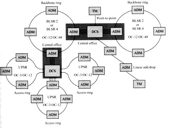
36 Sonet/SDH Infrastructure (2)
 Rings overlay, each at different wavelength BLSR architecture (Bidirectional Line-Switched Ring) 2 fibers (BLSR/2) or 4 fibers (BLSR/4) per ring Connections between multiple")
37 Sonet/SDH Ring networks Sonet ADM devices configurable as Ring ADM, linear ADM, TM Sonet rings composed by ADM Multiplexing, demultiplexing, fault protection Backbone rings OC-12/OC-48/OC-192 (now we move towards 40 Gbps) Rings overlay, each at different wavelength BLSR architecture (Bidirectional Line-Switched Ring) 2 fibers (BLSR/2) or 4 fibers (BLSR/4) per ring Connections between multiple central offices (CO) Access rings OC-3/OC-12 UPSR (Unidirectional Path-Switched Ring) architecture 1 fiber per ring In CO are connections between users and hub node

38 Sonet/SDH DCS (1) DCS (Digital CrossConnect) Basic component of Sonet network Manages all transmission resources DCS substitutes manual patch panels in CO Hundreds/thousands of ports Thousands of DS1/DS3 fluxes cannot be handled manually Automatic interconnection under software control, plus mux/demux and performance control Management of PDH, Sonet and SDH fluxes Traffic Grooming Traffic aggregation of similar type, QoS, destination Including mux/demux of low bitrate fluxes
39 Sonet/SDH DCS (2) Types of DCS Classified on the basis of grooming granularity Narrowband DCS Grooming at the level of DS0 flux Wideband DCS Grooming at the level of DS1 flux Broadband DCS Grooming at the level of DS3 (STS-1) flux Optical DCS (OXC) Grooming at the level of STS-48 flux, wavelength Fully optical DCS Interfaces from grooming bitrate up to higher bitrates Ex. broadband DCS interfaces from DS3 to OC-48
40 Clients of the optical layer Clients of optical layer Sonet/SDH ATM IP MPLS Storage-Area Networks Gigabit Ethernet RPR

41 ATM (1) ATM (Asynchronous Transfer Mode) Objective: integration between voice and data Traditionally, voice and data networks were separate ATM networks in LAN, MAN, WAN Packets (cells) with fixed dimension of 53 bytes 48 bytes of payload and 5 of overhead Compromise between voice and data requirements Voice prefers small packets Little delivery delay Data prefer big packets Less overhead Statistical cell multiplexing Efficient use of bandwidth Possibility to guarantee QoS Minimum bandwidth, maximum delay
42 ATM (2) Key point of ATM: guarantee of QoS Use of virtual circuits (VC) Knowledge of peak and average bandwidth for each VC Admission control for new connections Use of switching also in LAN This differentiates ATM from Ethernet, token ring and FDDI Easier to guarantee QoS in ATM LAN Fixed cell dimension Simple and inexpensive high speed switches Standard physical layers for ATM 25.6 Mbps on copper Mbps on monomode fiber Some standard optical interfaces 100 Mbps, with same parameters as FDDI Mbps with LED on MMF at 1310 nm
43 ATM (3) Private user-network interfaces Interfaces for interconnections between ATM users and switches of private businesses Ex. The two interfaces described in the previous slide Public user-network interfaces Interfaces for interconnection between ATM users and switches for public networks Use of PDH or Sonet/SDH as lower layer DS3, STS-3c, STS-12c, STS-48c ATM terminology Its lower layer is the physical layer (ex. Sonet) Interface ATM/Sonet: interface with physical level ISO/OSI layer model Sonet is data-link level of ATM
 is different in UNI and NNI GFC (Generic Flow Control): 4 (0) bit UNI (NNI) VPI (Virtual Path Identifier): 8 (12) bit UNI (NNI) VCI (Virtual Circuit Identifier): 16 bit PT (Payload")
44 ATM Functionalities UNI (User-to-Network Interface) Data transmitted from user to ATM network through a UNI NNI (Network-to-Network Interface) Data transmitted between ATM switches through a NNI Header (5 bytes) is different in UNI and NNI GFC (Generic Flow Control): 4 (0) bit UNI (NNI) VPI (Virtual Path Identifier): 8 (12) bit UNI (NNI) VCI (Virtual Circuit Identifier): 16 bit PT (Payload Type): 3 bit CLP (Cell Loss Priority): 1 bit HEC (Header Error Control): 8 bit CRC on 5 header bytes
45 ATM Connections Concept of end-to-end connection ATM service is connection-oriented Different from IP, which is connectionless ATM connection: virtual channel (VC) With VCI identifier It is unique for each link through which the connection goes through, but it may vary from link to link Ex. The upper connection has VCI a1, a2 e b on 0-3 link VCI determined at connection setup Released when connection is terminated Each switch handles a VCI table 3 columns: input VCI, exit VCI, output link
46 Virtual Paths (1) Millions of VC share same link VCI tables with more than elements are not manageable Aggregation of VCs by routing Thousands of VC with partially overlapping paths Use of virtual paths (VP), with VPI identifiers Ex. Two VCs share the path Common VPI assigned for each link Ex. x between 0 and 1, y between 1 and 2 Virtual path composed of 2 links 0 starting node, 2 destination node In the two links, routing using VPI Dal nodo 2 in poi, si usano i VCI
47 Virtual Paths (2) Advantages of two-levels routing Simplification of cell routing Development of low cost ATM switches Creation of logical links between nodes Virtual path between nodes is treated by VCs as logical link Ex. VP between 0 and 2 nodes is a logical link for the VCs When using VCI only 24 bit VCI for UNI, 28 bit for NNI Routing is complex and costly
 Segmentation and reassembly (SAR) AAL segments user data in ATM cells Reassembles them at destination ITU I.")
48 Adaptation layers Applications on ATM generate Continuous data fluxes (video, voice) Large dimension packets of variable size (IP) ATM uses fixed size cells (53 bytes) Necessity to map user data into cells Task of AAL (ATM Adaptation Layers) Segmentation and reassembly (SAR) AAL segments user data in ATM cells Reassembles them at destination ITU I.363 AAL standard: AAL-1, AAL-2, AAL-3/4, AAL-5 AAL-3 and AAL-4 are degenerate
 Passing to ATM level ATM adds its 5 bytes header The 47 payload bytes are not protected Adequate for voice/video")
49 AAL-1 Constant bitrate data trasport Voice, video Time continuous data flux Segmentation in 47 payload bytes AAL, 1 header byte AAL Header contains a sequence number Sequence number is protected by CRC (cyclic redundancy check) Passing to ATM level ATM adds its 5 bytes header The 47 payload bytes are not protected Adequate for voice/video transmission
50 AAL-5 Trasport of variable size packets Bytes with up to 2 16 = length Trasport of IP packets on ATM AAL-5 segments IP packets in ATM cells without adding overhead in each cell Use of PT field in the ATM header to indicate the last cell that forms the packet In the last cell, last 2 bytes are AAL header Length of IP packet and CRC of packet In all cells less one AAL payload coincides with the ATM one Reduced overhead with respect to AAL-1 CRC code on payload
51 Quality of Service QoS (1) ATM QoS Limitation on lost cells, delay and jitter Traffic shaping Contract with user on traffic characteristics Min and max cell rate, dimension of bursts that can be transfered through a UNI Cells that do not respect the contract are eliminated Otherwise their CLP (cell loss priority) is set These are eliminated first in case of congestion Accurate control of connection traffic In exchange, ATM guarantees high QoS Admission control Based on traffic shaping parameters New connections are accepted only if they are compatible with QoS of already existing connections
52 Service classes Quality of Service QoS (2) Chosen on the basis of traffic parameters and of the QoS Each connection belongs to a class Examples CBR (Constant Bit Rate) The connection specifies the peak cell rate and guarantees against cell loss, delay and jitter AAL-1 UBR (Unspecified Bit Rate) The connection specifies the peak cell rate, but without guarantee of QoS AAL-5 Complex queue management techniques Guarantee of QoS for connections of different classes
53 Flux control Routing (1) Flux control Control of user traffic not based on contract, but on network congestion Data traffic applications are not CBR controllable Ex. FTP Control through GFC bytes in UNI header Routing They signal if transmission should be enabled or blocked Routing protocols enable to build VCI e VPI tables at each switch Protocols are standardized by ATM forum PNNI (Private Network-to-Network Interface) B-ICI (Broadband Inter Carrier Interface)
54 Task PNNI Protocol Determine a path through the network from sender to receiver Necessary to provide the requested QoS State of the link Available bandwidth, lost cells, maximum delay Administrative cost, or weight Each switch performs flooding with the state of all output link with which it is connected to Each switch knows the state of all nodes When a new connection is requested Input switch compute path that guarantees QoS with minimum cost Path switches are informed of the new connection and of requested QoS
55 Client of optical layer Client of optical layer Sonet/SDH ATM IP MPLS Storage-Area Networks Gigabit Ethernet RPR
 Connection oriented FTP, Telnet, HTTP UDP (User Datagram")
56 IP (Internet Protocol) IP (1) The most widely used technology for WAN networks today Internet protocol for Internet and Intranet Connectionless service May work on many different data-link levels Ethernet, token ring, PPP, HDLC This is one of the reasons for the success of IP Transport protocols TCP (Transmission Control Protocol) Connection oriented FTP, Telnet, HTTP UDP (User Datagram Protocol) Connectionless Trasport of simple messages Streaming, NFS, SNMP
 IP packets mapped in PPP frame, coded in Sonet frame and transmitted on WDM channel IP over Gigabit Ethernet (c) 10 GE as MAC, IP packets coded in 10 GE frame and transmitted on WDM")
57 IP over WDM IP (2) Mapping of IP on the optical layer IP over ATM over Sonet (a) IP packets mapped in ATM cells, coded in Sonet frame and transmitted on a WDM channel Packet over Sonet, POS (b) IP packets mapped in PPP frame, coded in Sonet frame and transmitted on WDM channel IP over Gigabit Ethernet (c) 10 GE as MAC, IP packets coded in 10 GE frame and transmitted on WDM channel
58 Routing (1) IP packets have variable length Maximum dimension is bytes IP router is key element of internet networks Routing mechanism Each router has a routing table One or more entries for each destination router Indicates the adjacent node to to pass the packet The router searches in the packet header the destination address, hence it routes based on the table Management of routing tables in crucial for the network Routing protocols
59 Routing (2) Intra-domain routing protocols Ex. OSPF (Open Shortest Path First) protocol Each router samples the state of adjacent nodes If a state variation is found Flooding of the link state to all network nodes Modification of all routing tables based on the new informations All nodes know the current topology The flooding must be smart Old link state may arrive after a new one Sequence number assigned to each link state Link states with older sequence numbers are discarded Link states are periodically generated Since some of them could be lost
60 Routing (3) Link state packets provide to each router a global overview of the network Hence the router computes the optimum path between itself and other routers, and stores the next node for each destination Dijkstra algorithm It is impossibile that each router keeps the topology of the entire Internet Division of Internet in Autonomous Systems (AS) Intra-domain protocol (ex. OSPF) within the AS Inter-domain protocol for routing between AS Ex. BGP (Border Gateway Protocol) protocol
 Packets grouped in classes, indicated in the header Different classes, different treatment by routers Packets EF (Expedited Forwarding) Separate queue,")
61 Quality of Service QoS IP offers best effort service Packets undergo different paths, different delays, non-sequential delivery, in case of congestions packets are eliminated Strong demand for QoS in IP networks Diff-Serv (Differentiated Services) Packets grouped in classes, indicated in the header Different classes, different treatment by routers Packets EF (Expedited Forwarding) Separate queue, rapid delivery Assured Forwarding (AF) Indicates priority of discarding of packet Diff-Serv faces the QoS problem, but it cannot provide end-to-end guarantees Ex. One cannot say a priori if there is enough bandwidth for a new real-time traffic flux
62 Client of the optical layer Client of optical layer Sonet/SDH ATM IP MPLS Storage-Area Networks Gigabit Ethernet RPR

63 MPLS MPLS (Multi-Protocol Label Switching) Strong demand of end-to-end QoS in IP networks Delivery of different services differentiated by class Differentiation among different traffic types MPLS is layer between IP and data-link level (level 2.5) MPLS networks based on label switching concept Labels indicate path and attributes of services At network input, processing of packets Selection and use of proper label Internal routers read the label, apply the requested services in a proper way and route Routing based on label content Analysis and classification of packets at input only Network output: label is eliminated and delivery to destination
64 MPLS Label switching (1) Path of a packet along the network Step 1: classic construction of routing labels OSPF algorithm, also MPLS routers take part to it LDP protocol (Label Distribution Protocol) Uses routing tables to determine labels among adjacent nodes Creation of pre-configured LSP (Label Switching Paths) Step 2: a packet arrives at network input Edge Label Switching Router (LSR) LSR determines service of level 3 (QoS) LSR applies a label and routes the packet Step 3: at each node, LSR reads the label, substitutes it with a new one (from the table) and routes it Step 4: at the output, Edge LSR eliminates the label and routes to destination

65 MPLS Label switching (2)
66 MPLS Advantages (1) Paradigms of MPLS network Separate creation of LSP and routing Creation of LSP as network control functionality Hardware optimized for routing Both functionalities fully hardware implemented Label switching much simpler than IP routing Higher number of packets per second can be processed Concept of path in IP network IP routes without knowing the end-to-end connection MPLS permits to specify paths for packets Bandwidth optimization, congestion prevention, QoS Concept of end-to-end QoS in IP network Possibility to reserve bandwidth for a LSP LSP are distinguished on the basis of traffic type
67 MPLS Advantages (2) Greater reliability in case of a fault Definition of 2 LSP among the same nodes Fast switching in case of a fault IP routing is very inefficient and slow in such cases Creation of Virtual Private Networks (VPN) MPLS-based IP VPN Connectionless IP networks able to provide security and QoS through service classes Easy and efficient method to reduce costs to extend a LAN from intranet to extranet Traffic classification and routing according to the type Voce, video, Each VPN traffic is transported by a set of LSP A single infrastructure supports many VPN, so it is easy to add or erase a VPN Architecture for next generation IP services

68 MPLS - Applications Classes of service (CoS) Delivery of ad-hoc QoS for each CoS Ex. Guarantee of maximum delivery delay for a given CoS Streaming video Traffic engineering Path control to avoid network congestion Sending of data from Houston Singapore OSPF chooses the direct link A traffic jam may ultimately result MPLS may use a secondary link Bandwidth usage is optimized

69 GMPLS hints (1) Generalized MPLS Extension of MPLS to packet, TDM, wavelength, fiber switching Use of labels at all levels Problems with optical networks and TDM Devices are not designed to extract and process labels Discrete bandwidth allocation only Huge quantities of data and resources to manage Configuration of DCS, OXC is time-consuming Fault management (ex. 50 ms with Sonet)

70 Example GMPLS hints (2) IP routers connected to Sonet metro networks Metro networks connected via DWDM
71 GMPLS cenni (3) Generalised label It refers to packet, time-slot, wavelength or fiber
72 Client of optical layer Client of optical layer Sonet/SDH ATM IP MPLS Storage-Area Networks Gigabit Ethernet RPR

73 Storage-Area Networks (1) SAN (Storage Area Networks) Networks for connections between computers and other devices Useful for business with big datacenters The key element is an electronic switch Connections among devices are reconfigurable Circuit switching connections In the past, SAN limited to a building or campus Now SAN extends to metro level, or even long haul Reliability against disasters (backup) Delocalization of datacenters (cost reduction)
74 Storage-Area Networks (2) Bitrates typically between 200 Mbps and 1 Gbps on fiber Not very high bitrate, the keypoint for the optical layer is the number of connections From hundreds to thousands of links between datacenters Main SAN technologies ESCON (Enterprise Serial Connection) Fibre Channel HIPPI (High Performance Parallel Interface) Use of line coding for fiber transmission Data rate (Mbytes/s) vs. transmission rate (Mbaud/s)

75 ESCON Developed by IBM at the end of the 80 Substitutes the ineffective, slow copper connections Widely used to connect mainframes Data rate 17 Mbytes/s Overhead and line coding (8, 10), 200 Mbaud/s Physical level MMF fiber at 1310 nm with LED sources for L < 3 km SMF fiber at 1310 nm with MLM sources for L < 20 km Data-link level: stop-and-wait Sending of data, then wait for ACK before new block Reduction of throughput as length grows Heavy liniting factor with ESCON Specifications on maximum interconnection distances
76 Fibre Channel Standard developed at the end of the 90 Same applications as ESCON, with I/O ports on peripherals and computer, electrical switching Widely used until now The standard includes a large veriety of bitrates Starting from the full speed version at 100 Mbytes/s Version at ¼ speed (25 Mbytes/s) Version at 400 Mbytes/s Line coding (8, 10) as in ESCON Use of both copper and fiber interfaces Copper up to 100 Mbytes/s, fiber beyond
77 HIPPI Widely used for supercomputer links Parallel electical interface at 100 Mbytes/s Clock skew limits maximum distance to 25 m Beyond 25 m HIPPI is made serial and transmitted over fiber Serial HIPPI, optical interfaces up to 1.2 Gbaud Other versions Serial interface at 200 Mbytes/s with 2 fibers 12 fiber interface, each at 100 Mbytes/s HIPPI competitor of Fibre Channel and ESCON HIPPI network composed by host and peripherals connected to HIPPI switches by optical fibers
78 Client of optical layer Client of optical layer Sonet/SDH ATM IP MPLS Storage-Area Networks Gigabit Ethernet RPR
79 10 Gigabit Ethernet (1) Almost all Internet traffic originates and is delivered to Ethernet networks Low cost, reliable, simple to install The evolution of Ethernet (born 40 years ago) goes towards the requirements of modern packed networks Standard 10 Gigabit Ethernet Extension of protocols IEEE at 10 Gbps bitrate and to applications on WAN links (IEEE 802.3ae) Full compatibility with previous versions IEEE GE maintains the traditional Ethernet architecture It is a protocol of level 1 and 2 Necessity of a MAC (Media Access Control) Format and dimensions of frames The evolution continues in terms of bitrate and distance

80 10 Gigabit Ethernet (2) Only a difference between Ethernet and 10 GE 10 GE is full-duplex technology Protocol CSMA-CD is not necessary Architecture of protocol IEEE 802.3ae Livello data-link PCS Livello fisico (PHY) PMA + PMD
81 10 Gigabit Ethernet (3) MAC connected to physical level (PHY) through a medium indipendent interface (XGMII) Physical lavel divided in 3 sublevels PMD (Physical Media Dependent) Provides physical connection to the medium Ex. transceivers are PMDs PMA (Physical Medium Attachment) PCS (Physical Coding Sublayer) Provides coding (ex. 64B/66B) and multiplexing Two different types of PHY LAN PHY WAN PHY Similar to LAN PHY, but the PCS permits the connection with Sonet STS-192
82 10 Gigabit Ethernet - PMD IEEE 802.3ae defines 4 PMD Serial PMD at 1310 nm, monomode fiber on maximum distance of 10 km Serial PMD at 1550 nm, monomode fiber on maximum distance of 40 km Serial PMD at 850 nm, multimode fiber on maximum distance of 300 m PMD WWDM (Wide-Wave WDM) at 1310 nm, monomode fiber on maximum distance of 10 km or multimode fiber on maximum distance of 300 m

83 10 Gigabit Ethernet - Advantages Basic ethernet is most adopted technology for LAN Ever growing bandwidth request Convergence of voice and data networks on Ethernet 10 GE supports bitrates up to 10 Gbps on distances up to 40 km Multimode fibers Monomode fibers Distance spans from 5 to 40 km Use of VCSEL sources In general, possible to use low cost optics Natural choice for expansion of existing Ethernet networks Ethernet has easy interoperability with 10 GE Basic knowledge and management are very similar Standard products available from several vendors
84 10 Gigabit Ethernet Applications (1) Packets leave the server through a 10 GE short-haul connection, move on a DWDM network and arrive to a PC connected to a GE port No protocol conversion or re-framing Server connection Proprietary solutions High cost, difficult management and maintanance Fibre Channel Standard but costly, low interoperability, not well known by personnel 10 Gigabit Ethernet Optimal solution for server interconnection Offers sufficient bandwidth (10 Gbps) Single server sufficient bandwidth to replace many others Low latency time, crucial for clustering

85 10 Gigabit Ethernet Applications (2) LAN Guarantee of greater bandwidth on longer distances Support of multimode and monomode fibers Possible ad hoc choice of server and datacenter location within 40 km Backbone 10 GE short-haul multimode fiber for switchswitch and server-switch connections Low cost, high performances Low link congestion, low latency

86 10 Gigabit Ethernet Applications (3) MAN/SAN Excellent solution for backbone of metro networks Use of SMF, link up to 40 km that can reach all customers in a city WAN Links with high performances between switches/routers connected to Sonet/SDH networks Interfaces WAN PHY LAN connected by Sonet/SDH through DWDM
87 Client of the optical layer Client of the optical layer Sonet/SDH ATM IP MPLS Storage-Area Networks Gigabit Ethernet RPR

88 RPR (1) RPR (Resilient Packet Ring) Migration of packet-based networks from LAN to MAN Data traffic ever increasing, difficult to trasport on Sonet/SDH networks which are optimized for voice Solution: packet networks also in metro networks Ethernet handles in optimal way IP packets as well 10 GE has enough speed for metro networks However Most of installed MAN are ring type High reliability, fast restoration (< 60 ms) Ethernet not adapted to ring networks Missing the MAC for ring management! Ethernet has no protection mechanisms
 Fast recovery from faults (as in Sonet) Simple, efficient (as Ethernet) Equity in management of resources Management of network congestion")
89 RPR (2) Necessity of new technology that Exploits at best the characteristics of rings Maintaining advantages of packet transport RPR emerging technology for transport on metro networks Efficient support of rings (as in Sonet) Fast recovery from faults (as in Sonet) Simple, efficient (as Ethernet) Equity in management of resources Management of network congestion problems

90 Sonet Metro Ring Ring is natural configuration for Sonet/SDH Sonet born for point-to-point circuit switching Many disadvantages in data transport using Sonet Fixed circuits Bandwidth waste if the circuit not used Waste of bandwidth for logic mesh Difficult and inefficient to create logic mesh Bad management of multicast traffic A circuit and a packet for each destination Waste of bandwidth for protection Tipically 50%

91 Ethernet Metro Ring Ethernet uses the available bandwidth in efficient way But it does not use efficiently the ring topology No efficient ring protection system Ethernet protection only active at link level, and very slow 500 ms compared with 50 ms with Sonet Non equal management of the shared medium Equity only present at link level Which does not translate into global equity Ethernet is on the ring but it does not know about it! Logical scheme in figure below
 New MAC protocol for metro ring networks Packet ADM architecture (Add/Drop Mux) Comparison between Packet ADM and Ethernet switch Ethernet network composed by point-to-point links Queueing and")
92 RPR philosophy Resilient Packet Ring (1) The problem of managing the shared medium is solved at the MAC level RPR (IEEE ) New MAC protocol for metro ring networks Packet ADM architecture (Add/Drop Mux) Comparison between Packet ADM and Ethernet switch Ethernet network composed by point-to-point links Queueing and routing at each node Each node processes the traffic that enters at the line rate Beyond 10 Gbps, this approach is no longer valid
93 Resilient Packet Ring (2) RPR has the notion of transit traffic Traffic not delivered to the node passes without queueing The MAC has 3 functions Add: insertion of new traffic Drop: drop of part of the traffic Pass: transit without processing Transit path is part of transmission medium RPR ring is a continuous medium shared among nodes Packet ADM architecture does not process transit traffic High scalability at large bitrates
94 Resilient Packet Ring Advantages (1) Versatility at the physical level RPR defines a single standard for MAC At level 1 you may have Ethernet, Sonet, DWDM Reliability Efficient recovery mechanism: ring wrap In case of fault, you may reach the destination by going through the ring in the opposite direction
95 Resilient Packet Ring Advantages (2) Equitable bandwidth management A shared ring is very sensitive to excessive usage by some users Necessary to guarantee equitable bandwidth management At global ring level, and not link by link! This is impossible with Sonet and with Ethernet Sonet user utilises resources, Ethernet non equal usage There is a feedback mechanism in RPR Traffic monitoring (task of MAC) Traffic data delivered to all nodes Sources modify the traffic accordingly Non-equity of Ethernet in bandwidth management gets worse when number of nodes increases!
96 Resilient Packet Ring Advantages (3) Multicast traffic management Packet ring is ideal configuration Only one copy of a packet circulates in the ring Simplified service delivery Activation times in Sonet networks are high Ex. DS1, DS3 require weeks Activation is immediate in RPR ring Ring is shared medium, all nodes have global vision of the network
97 Resilient Packet Ring - Applications RPR is useful each time data are transported on fiber ring Ex. Metro Service Provider, DSL access network A single RPR ring connects multiple buildings in the area High reliability (< 50 ms), easy to drop at nodes Bandwidth is equally divided among users
")
 vs.")
98 RPR case study (1) Sonet/SDH (1) vs. RPR (2) (1) (2)

99 RPR case study (2) Case users equally distributed among 5 nodes 1.5 Mbps per user

100 RPR Case study (3) Case 2 Bitrate upgrade for everybody at 5 Mbps

101 Case 3 RPR Case study (4) Strong increase of user bitrate 80 users at 40 Mbps, 10 at 100 Mbps, 10 at 1 Gbps

102 Case 4 RPR Case study (5) 10 fold increase of number of users 80% at 40 Mbps, 10% at 10 Mbps, 10% at 1 Gbps
 Resolution of TDM granularity problem Ethernet 100 Mbps transported in 2 STS-1 (~ 2 x 52 Mbps = 104 Mbps) Ethernet 1 Gbps transported in 21 STS-1 (~ 21 x 52")
103 RPR Case study (6) Case 5 Same services requested as in case 4 New generation Sonet systems Use of Ethernet interfaces mapped on Sonet/SDH networks VCAT (Virtual Concatenation) Resolution of TDM granularity problem Ethernet 100 Mbps transported in 2 STS-1 (~ 2 x 52 Mbps = 104 Mbps) Ethernet 1 Gbps transported in 21 STS-1 (~ 21 x 52 Mbps = Gbps)
")
104 RPR Case study (7)
SDH and WDM A look at the physical layer
 SDH and WDM A look at the physical Andrea Bianco Telecommunication Network Group [email protected] http://www.telematica.polito.it/ Network management and QoS provisioning - 1 Copyright This
SDH and WDM: a look at the physical layer
 SDH and WDM: a look at the physical SDH and WDM A look at the physical Andrea Bianco Telecommunication Network Group [email protected] http://www.telematica.polito.it/ Network management and
Course 12 Synchronous transmission multiplexing systems used in digital telephone networks
 Course 12 Synchronous transmission multiplexing systems used in digital telephone networks o Disadvantages of the PDH transmission multiplexing system PDH: no unitary international standardization of the
Optical Communication Networks. Transport networks
 Optical Communication Networks Transport networks Corso di Laurea Specialistica in Ingegneria delle Telecomunicazioni A.A. 2009/2010 Transport networks (1) Transport networks Evolution of TLC networks
Master Course Computer Networks IN2097
 Chair for Network Architectures and Services Prof. Carle Department for Computer Science TU München Master Course Computer Networks IN2097 Prof. Dr.-Ing. Georg Carle Christian Grothoff, Ph.D. Chair for
Lecture 12 Transport Networks (SONET) and circuit-switched networks
 and circuit-switched networks") CS4/MSc Computer Networking Lecture 1 Transport Networks (SONET) and circuit-switched networks Computer Networking, Copyright University of Edinburgh 005 Transport Networks and SONET/SDH In most cases
CS4/MSc Computer Networking Lecture 1 Transport Networks (SONET) and circuit-switched networks Computer Networking, Copyright University of Edinburgh 005 Transport Networks and SONET/SDH In most cases
Introduction. Background
 Introduction By far, the most widely used networking technology in Wide Area Networks (WANs) is SONET/SDH. With the growth of Ethernet now into Metropolitan Area Networks (MANs) there is a growing need
Raj Jain. The Ohio State University Columbus, OH 43210 [email protected] These slides are available on-line at:
 IP Over SONET The Ohio State University Columbus, OH 43210 [email protected] These slides are available on-line at: http://www.cis.ohio-state.edu/~jain/cis788-99/h_bipsn.htm 1 Overview IP over SONET:
Link Layer. 5.6 Hubs and switches 5.7 PPP 5.8 Link Virtualization: ATM and MPLS
 Link Layer 5.1 Introduction and services 5.2 Error detection and correction 5.3Multiple access protocols 5.4 Link-Layer Addressing 5.5 Ethernet 5.6 Hubs and switches 5.7 PPP 5.8 Link Virtualization: and
DigiPoints Volume 1. Student Workbook. Module 5 Growing Capacity Through Technology
 Growing Capacity Through Technology Page 5. 1 DigiPoints Volume 1 Module 5 Growing Capacity Through Technology Summary This module covers the North American Digital Hierarchy (NADH), the European Digital
WAN. Introduction. Services used by WAN. Circuit Switched Services. Architecture of Switch Services
 WAN Introduction Wide area networks (WANs) Connect BNs and LANs across longer distances, often hundreds of miles or more Typically built by using leased circuits from common carriers such as AT&T Most
A review of Plesiochronous Digital Hierarchy (PDH) and Synchronous Digital Hierarchy (SDH)
 and Synchronous Digital Hierarchy (SDH)") 677 A review of Plesiochronous Digital Hierarchy (PDH) and Synchronous Digital Hierarchy (SDH) Olabenjo Babatunde 1, Salim Mbarouk 2 1 (Department of Information Systems Engineering, Cyprus International
677 A review of Plesiochronous Digital Hierarchy (PDH) and Synchronous Digital Hierarchy (SDH) Olabenjo Babatunde 1, Salim Mbarouk 2 1 (Department of Information Systems Engineering, Cyprus International
Deploying Multiservice Applications Using RPR Over the Existing SONET Infrastructure
 Deploying Multiservice Applications Using RPR Over the Existing SONET Infrastructure Introduction The migration of Ethernet technology from the LAN to metro networks, driven by increasing demand in VoIP,
It explains the differences between the Plesiochronous Digital Hierarchy and the Synchronous Digital Hierarchy.
 TECHNICAL TUTORIAL Subject: SDH Date: October, 00 Prepared by: John Rumsey SDH Synchronous Digital Hierarchy. Introduction. The Plesiochronous Digital Hierarchy (PDH). The Synchronous Digital Hierarchy
Chapter 2 - The TCP/IP and OSI Networking Models
 Chapter 2 - The TCP/IP and OSI Networking Models TCP/IP : Transmission Control Protocol/Internet Protocol OSI : Open System Interconnection RFC Request for Comments TCP/IP Architecture Layers Application
MPLS and IPSec A Misunderstood Relationship
 # 129 TECHNOLOGY WHITE PAPER Page: 1 of 5 MPLS and IPSec A Misunderstood Relationship Jon Ranger, Riverstone Networks ABSTRACT A large quantity of misinformation and misunderstanding exists about the place
Asynchronous Transfer Mode
 CHAPTER 15 Asynchronous Transfer Mode Background Asynchronous Transfer Mode (ATM) technology is based on the efforts of the International Telecommunication Union Telecommunication Standardization Sector
Computer Network. Interconnected collection of autonomous computers that are able to exchange information
 Introduction Computer Network. Interconnected collection of autonomous computers that are able to exchange information No master/slave relationship between the computers in the network Data Communications.
Lecture Computer Networks
 Lecture Computer Networks Prof. Dr. Hans Peter Großmann mit M. Rabel sowie H. Hutschenreiter und T. Nau Sommersemester 2012 Institut für Organisation und Management von Informationssystemen Asynchronous
Chap 4 Circuit-Switching Networks
 hap 4 ircuit-switching Networks Provide dedicated circuits between users Example: 1. telephone network: provides 64Kbps circuits for voice signals 64Kbps=8 k samples/sec * 8 bits/sample 2. transport network:
ATM. Asynchronous Transfer Mode. Networks: ATM 1
 ATM Asynchronous Transfer Mode Networks: ATM 1 Issues Driving LAN Changes Traffic Integration Voice, video and data traffic Multimedia became the buzz word One-way batch Two-way batch One-way interactive
10 Gigabit Ethernet WAN PHY
 White PAPER 10 Gigabit Ethernet WAN PHY Introduction The introduction of 10 Gigabit Ethernet (10 GbE) WAN PHY into the IP/Ethernet networking community has led to confusion over the applicability between
QoS Switching. Two Related Areas to Cover (1) Switched IP Forwarding (2) 802.1Q (Virtual LANs) and 802.1p (GARP/Priorities)
 Switched IP Forwarding (2) 802.1Q (Virtual LANs) and 802.1p (GARP/Priorities)") QoS Switching H. T. Kung Division of Engineering and Applied Sciences Harvard University November 4, 1998 1of40 Two Related Areas to Cover (1) Switched IP Forwarding (2) 802.1Q (Virtual LANs) and 802.1p
QoS Switching H. T. Kung Division of Engineering and Applied Sciences Harvard University November 4, 1998 1of40 Two Related Areas to Cover (1) Switched IP Forwarding (2) 802.1Q (Virtual LANs) and 802.1p
10 Gigabit Ethernet: Scaling across LAN, MAN, WAN
 Arasan Chip Systems Inc. White Paper 10 Gigabit Ethernet: Scaling across LAN, MAN, WAN By Dennis McCarty March 2011 Overview Ethernet is one of the few protocols that has increased its bandwidth, while
Communication Networks. MAP-TELE 2011/12 José Ruela
 Communication Networks MAP-TELE 2011/12 José Ruela Network basic mechanisms Introduction to Communications Networks Communications networks Communications networks are used to transport information (data)
FURTHER READING: As a preview for further reading, the following reference has been provided from the pages of the book below:
 FURTHER READING: As a preview for further reading, the following reference has been provided from the pages of the book below: Title: Broadband Telecommunications Handbook Author: Regis J. Bud Bates Publisher:
Gigabit Ethernet: Architectural Design and Issues
 Gigabit Ethernet: Architectural Design and Issues Professor of Computer and Information Sciences Columbus, OH 43210 http://www.cis.ohio-state.edu/~jain/ 9-1 Overview Distance-Bandwidth Principle 10 Mbps
Computer Networks. Definition of LAN. Connection of Network. Key Points of LAN. Lecture 06 Connecting Networks
 Computer Networks Lecture 06 Connecting Networks Kuang-hua Chen Department of Library and Information Science National Taiwan University Local Area Networks (LAN) 5 kilometer IEEE 802.3 Ethernet IEEE 802.4
New WAN PHY Approach Proposals
 New WAN Approach Proposals Feed Forward Rate Control (FFRC) & 10Gigabit Ethernet Network Interface Extension (10GENIE) IEEE P802.3ae 6-10 March, 2000 Albuquerque, NM Osamu ISHIDA and Haruhiko ICHINO NTT
ICS 153 Introduction to Computer Networks. Inst: Chris Davison [email protected]
 ICS 153 Introduction to Computer Networks Inst: Chris Davison [email protected] 1 ICS 153 Introduction to Computer Networks Course Goals Understand the basic principles of computer networks Design Architecture
Frame Relay and Frame-Based ATM: A Comparison of Technologies
 White Paper and -Based : A Comparison of Technologies Larry Greenstein Nuera Communications VP, Technology, Forum June 1995 June 27, 1995 i TABLE OF CONTENTS 1. PREFACE...1 2. INTRODUCTION...1 3. INTERWORKING
Protocol Overhead in IP/ATM Networks
 Protocol Overhead in IP/ATM Networks John David Cavanaugh * Minnesota Supercomputer Center, Inc. This paper discusses the sources of protocol overhead in an IP/ATM protocol stack. It quantifies the amount
WAN Data Link Protocols
 WAN Data Link Protocols In addition to Physical layer devices, WANs require Data Link layer protocols to establish the link across the communication line from the sending to the receiving device. 1 Data
Local Area Networks transmission system private speedy and secure kilometres shared transmission medium hardware & software
 Local Area What s a LAN? A transmission system, usually private owned, very speedy and secure, covering a geographical area in the range of kilometres, comprising a shared transmission medium and a set
High Speed Ethernet. Dr. Sanjay P. Ahuja, Ph.D. Professor School of Computing, UNF
 High Speed Ethernet Dr. Sanjay P. Ahuja, Ph.D. Professor School of Computing, UNF Hubs and Switches Hubs and Switches Shared Medium Hub The total capacity in the shared medium hub configuration (figure
Asynchronous Transfer Mode: ATM. ATM architecture. ATM: network or link layer? ATM Adaptation Layer (AAL)
") Asynchrous Transfer Mode: architecture 1980s/1990 s standard for high-speed (155Mbps to 622 Mbps and higher) Broadband Integrated Service Digital Network architecture Goal: integrated, end-end transport
Asynchrous Transfer Mode: architecture 1980s/1990 s standard for high-speed (155Mbps to 622 Mbps and higher) Broadband Integrated Service Digital Network architecture Goal: integrated, end-end transport
White paper. Reliable and Scalable TETRA networks
 Abstract The evolution of TETRA networks towards an all- IP architecture is now a reality and has been accepted by even the most demanding users of TETRA technology. Although circuit switch based TETRA
CTS2134 Introduction to Networking. Module 07: Wide Area Networks
 CTS2134 Introduction to Networking Module 07: Wide Area Networks WAN cloud Central Office (CO) Local loop WAN components Demarcation point (demarc) Consumer Premises Equipment (CPE) Channel Service Unit/Data
Overview of Asynchronous Transfer Mode (ATM) and MPC860SAR. For More Information On This Product, Go to: www.freescale.com
 and MPC860SAR. For More Information On This Product, Go to: www.freescale.com") Overview of Asynchronous Transfer Mode (ATM) and MPC860SAR nc. 2 What is ATM? o Protocol that applies primarily to layer 2 of the OSI protocol stack: Application Presentation Session Transport Network
Overview of Asynchronous Transfer Mode (ATM) and MPC860SAR nc. 2 What is ATM? o Protocol that applies primarily to layer 2 of the OSI protocol stack: Application Presentation Session Transport Network
Module 4. Switched Communication Networks. Version 2 CSE IIT, Kharagpur
 Module 4 Switched Communication Networks Lesson 6 Asynchronous Transfer Mode Switching (ATM) Specific Instructional Objectives On completion on this lesson, the student will be able to: State the need
Protocol Architecture. ATM architecture
 Asynchronous Transfer Mode (ATM) Asynchronous Transfer Mode: ATM 1990 s/00 standard for high-speed (155Mbps to 622 Mbps and higher) Broadband Integrated Service Digital Network architecture Goal: integrated,
MPLS L2VPN (VLL) Technology White Paper
 Technology White Paper") MPLS L2VPN (VLL) Technology White Paper Issue 1.0 Date 2012-10-30 HUAWEI TECHNOLOGIES CO., LTD. 2012. All rights reserved. No part of this document may be reproduced or transmitted in any form or by any
MPLS L2VPN (VLL) Technology White Paper Issue 1.0 Date 2012-10-30 HUAWEI TECHNOLOGIES CO., LTD. 2012. All rights reserved. No part of this document may be reproduced or transmitted in any form or by any
10G CWDM Conversion Technology
 10G CWDM Conversion Technology Simplifying Today s Challenges By Transition Networks Curt Carlson Product Manager [email protected] com Agenda WDM Technology Overview What are the features/benefits
BCS THE CHARTERED INSTITUTE FOR IT. BCS HIGHER EDUCATION QUALIFICATIONS BCS Level 5 Diploma in IT COMPUTER NETWORKS
 BCS THE CHARTERED INSTITUTE FOR IT BCS HIGHER EDUCATION QUALIFICATIONS BCS Level 5 Diploma in IT COMPUTER NETWORKS Friday 2 nd October 2015 Morning Answer any FOUR questions out of SIX. All questions carry
Computer Networks CS321
 Computer Networks CS321 Dr. Ramana I.I.T Jodhpur Dr. Ramana ( I.I.T Jodhpur ) Computer Networks CS321 1 / 22 Outline of the Lectures 1 Introduction OSI Reference Model Internet Protocol Performance Metrics
Quality of Service in the Internet. QoS Parameters. Keeping the QoS. Traffic Shaping: Leaky Bucket Algorithm
 Quality of Service in the Internet Problem today: IP is packet switched, therefore no guarantees on a transmission is given (throughput, transmission delay, ): the Internet transmits data Best Effort But:
ICTTEN6172A Design and configure an IP- MPLS network with virtual private network tunnelling
 ICTTEN6172A Design and configure an IP- MPLS network with virtual private network tunnelling Release: 1 ICTTEN6172A Design and configure an IP-MPLS network with virtual private network tunnelling Modification
WHITEPAPER MPLS: Key Factors to Consider When Selecting Your MPLS Provider
 WHITEPAPER MPLS: Key Factors to Consider When Selecting Your MPLS Provider INTRODUCTION Multiprotocol Label Switching (MPLS), once the sole domain of major corporations and telecom carriers, has gone mainstream
IP Networking. Overview. Networks Impact Daily Life. IP Networking - Part 1. How Networks Impact Daily Life. How Networks Impact Daily Life
 Overview Dipl.-Ing. Peter Schrotter Institute of Communication Networks and Satellite Communications Graz University of Technology, Austria Fundamentals of Communicating over the Network Application Layer
An Introduction to Resilient Packet Ring Technology
 An Introduction to Resilient Packet Ring Technology A White Paper by the Resilient Packet Ring Alliance October 2001 An Introduction to Resilient Packet Ring Technology Table of Contents 1.0 Introduction...
Local Area Networks (LANs) Blueprint (May 2012 Release)
 Blueprint (May 2012 Release)") Local Area Networks (LANs) The CCNT Local Area Networks (LANs) Course April 2012 release blueprint lists the following information. Courseware Availability Date identifies the availability date for the
Local Area Networks (LANs) The CCNT Local Area Networks (LANs) Course April 2012 release blueprint lists the following information. Courseware Availability Date identifies the availability date for the
Performance Management for Next- Generation Networks
 Performance Management for Next- Generation Networks Definition Performance management for next-generation networks consists of two components. The first is a set of functions that evaluates and reports
Basic Networking Concepts. 1. Introduction 2. Protocols 3. Protocol Layers 4. Network Interconnection/Internet
 Basic Networking Concepts 1. Introduction 2. Protocols 3. Protocol Layers 4. Network Interconnection/Internet 1 1. Introduction -A network can be defined as a group of computers and other devices connected
Introduction to Carrier Network Architectures
 1 Introduction to Carrier Network Architectures In the first chapter, we give an overview about existing and possible future Carrier Network Architectures. We will explain the traditional architectural
Ethernet Over SONET. Technology White Paper. Mimi Dannhardt Technical Advisor
 Mimi Dannhardt Technical Advisor Issue 1: February, 2002 PMC-2020296 Abstract This White Paper describes the use of the new ITU G.7041 GFP and ITU G.7042 LCAS standards to provide Ethernet leased line
Transport and Network Layer
 Transport and Network Layer 1 Introduction Responsible for moving messages from end-to-end in a network Closely tied together TCP/IP: most commonly used protocol o Used in Internet o Compatible with a
MPLS: Key Factors to Consider When Selecting Your MPLS Provider Whitepaper
 MPLS: Key Factors to Consider When Selecting Your MPLS Provider Whitepaper 2006-20011 EarthLink Business Page 1 EXECUTIVE SUMMARY Multiprotocol Label Switching (MPLS), once the sole domain of major corporations
Distributed Systems 3. Network Quality of Service (QoS)
") Distributed Systems 3. Network Quality of Service (QoS) Paul Krzyzanowski [email protected] 1 What factors matter for network performance? Bandwidth (bit rate) Average number of bits per second through
Distributed Systems 3. Network Quality of Service (QoS) Paul Krzyzanowski [email protected] 1 What factors matter for network performance? Bandwidth (bit rate) Average number of bits per second through
Communications and Computer Networks
 SFWR 4C03: Computer Networks and Computer Security January 5-8 2004 Lecturer: Kartik Krishnan Lectures 1-3 Communications and Computer Networks The fundamental purpose of a communication system is the
QoS Parameters. Quality of Service in the Internet. Traffic Shaping: Congestion Control. Keeping the QoS
 Quality of Service in the Internet Problem today: IP is packet switched, therefore no guarantees on a transmission is given (throughput, transmission delay, ): the Internet transmits data Best Effort But:
A Brief Overview of SONET Technology
 A Brief Overview of SONET Technology Document ID: 13567 Contents Introduction Prerequisites Requirements Components Used Conventions SONET Basics SONET Transport Hierarchy Configuration Example SONET Framing
CS 5516 Computer Architecture Networks
 Lecture 11: ISDN & ATM CS 5516 Computer Architecture Networks VA Tech Prof. Roy M. Wnek History of ISDN Traditionally, local loop connectivity has been with an analog signal on copper Inefficient, prone
Primary Data Center. Remote Data Center Plans (COOP), Business Continuity (BC), Disaster Recovery (DR), and data
, Business Continuity (BC), Disaster Recovery (DR), and data") White Paper Storage Extension Network Solutions Between Data Centers Simplified, Low Cost, Networks for Storage Replication, Business Continuity and Disaster Recovery TODAY S OPERATING CLIMATE DEMANDS
White Paper Storage Extension Network Solutions Between Data Centers Simplified, Low Cost, Networks for Storage Replication, Business Continuity and Disaster Recovery TODAY S OPERATING CLIMATE DEMANDS
LECTURE 5: Wide Area Networks (WANs) CIS484. Communications Systems. Summer 2015 Instructor: Dr. Song Xing
 CIS484. Communications Systems. Summer 2015 Instructor: Dr. Song Xing") LECTURE 5: Wide Area Networks (WANs) CIS484 Summer 2015 Instructor: Dr. Song Xing Department of Information Systems California State University, Los Angeles Outlines Introduction to WAN Point-to-point
LECTURE 5: Wide Area Networks (WANs) CIS484 Summer 2015 Instructor: Dr. Song Xing Department of Information Systems California State University, Los Angeles Outlines Introduction to WAN Point-to-point
Computer Networks II
 Computer Networks II SDH Giorgio Ventre COMICS LAB Dipartimento di Informatica e Sistemistica Università di Napoli Federico II Nota di Copyright Quest insieme di trasparenze è stato ideato e realizzato
1.264 Lecture 37. Telecom: Enterprise networks, VPN
 1.264 Lecture 37 Telecom: Enterprise networks, VPN 1 Enterprise networks Connections within enterprise External connections Remote offices Employees Customers Business partners, supply chain partners Patients
Course 13 SDH/SONET multiplexing strategy
 Course SDH/SONET multiplexing strategy Elements of the SDH/SONET multiplex o Container C represents a bloc structure with imposed dimensions which contains data belonging to a tributary and doesn t contain
Broadband Networks. Prof. Abhay Karandikar. Electrical Engineering Department. Indian Institute of Technology, Mumbai.
 Broadband Networks Prof. Abhay Karandikar Electrical Engineering Department Indian Institute of Technology, Mumbai Lecture - 32 Metro Ethernet Access Networks So, in today s lecture we will talk about
Chapter 11: WAN. Abdullah Konak School of Information Sciences and Technology Penn State Berks. Wide Area Networks (WAN)
") Chapter 11: WAN Abdullah Konak School of Information Sciences and Technology Penn State Berks Wide Area Networks (WAN) The scope of a WAN covers large geographic areas including national and international
Chapter 11: WAN Abdullah Konak School of Information Sciences and Technology Penn State Berks Wide Area Networks (WAN) The scope of a WAN covers large geographic areas including national and international
H3C SR8800 RPR Technology White Paper
 H3C 00 RPR Technology White Paper Keywords: RPR, IP ring network Abstract: Resilient Packet Ring (RPR) is an international standard for establishing IP ring networks, offering a highly efficient and reliable
LAN and WAN Rate 10 GigE
 LAN and WAN Rate 10 GigE IEEE 802.3 Sept. 27, 1999 Paul A. Bottorff Nortel Networks 1 Agenda A 2 PHYs Solution is the Way To Go LAN PHY compatible with LAN market LAN PHY provides connections up to 40
APPLICATION NOTE 211 MPLS BASICS AND TESTING NEEDS. Label Switching vs. Traditional Routing
 MPLS BASICS AND TESTING NEEDS By Thierno Diallo, Product Specialist Protocol Business Unit The continuing expansion and popularity of the Internet is forcing routers in the core network to support the
How To Build A Network For Storage Area Network (San)
") White Paper Data Storage across the MAN by deploying a SAN over Dark Fiber by Pieter Panis, EuroFiber 1/7 1 Introduction The purpose of this document is to illustrate how a storage area network (SAN) can
White Paper Data Storage across the MAN by deploying a SAN over Dark Fiber by Pieter Panis, EuroFiber 1/7 1 Introduction The purpose of this document is to illustrate how a storage area network (SAN) can
Internet Dagarna 2000
 Internet Dagarna 2000 October 24th 2000 2000, Cisco Systems, Inc. 1 Dennis Davidsson Director Market Development Public Carrier IP Group 2 What s Driving the Demand? 3 How How How Many Many Many of of
Bandwidth Profiles for Ethernet Services Ralph Santitoro
 Ralph Santitoro Abstract This paper provides a comprehensive technical overview of bandwidth profiles for Ethernet services, based on the work of the Metro Ethernet Forum (MEF) Technical Committee. The
Ethernet. Ethernet. Network Devices
 Ethernet Babak Kia Adjunct Professor Boston University College of Engineering ENG SC757 - Advanced Microprocessor Design Ethernet Ethernet is a term used to refer to a diverse set of frame based networking
Alcatel-Lucent 1665 Data Multiplexer (DMX) for Service Providers
 for Service Providers") Alcatel-Lucent 1665 Data Multiplexer (DMX) for Service Providers Bridges the bandwidth gap between LANs and core backbone networks. Offers multiservice growth from traditional voice/private line services
Alcatel-Lucent 1665 Data Multiplexer (DMX) for Service Providers Bridges the bandwidth gap between LANs and core backbone networks. Offers multiservice growth from traditional voice/private line services
What is CSG150 about? Fundamentals of Computer Networking. Course Outline. Lecture 1 Outline. Guevara Noubir [email protected].
 What is CSG150 about? Fundamentals of Computer Networking Guevara Noubir [email protected] CSG150 Understand the basic principles of networking: Description of existing networks, and networking mechanisms
Chapter 9A. Network Definition. The Uses of a Network. Network Basics
 Chapter 9A Network Basics 1 Network Definition Set of technologies that connects computers Allows communication and collaboration between users 2 The Uses of a Network Simultaneous access to data Data
BROADBAND AND HIGH SPEED NETWORKS
 BROADBAND AND HIGH SPEED NETWORKS INTRODUCTION TO MUTIPLEXING Multiplexing is the set of techniques that allows the simultaneous transmission of multiple signals across a single data link INTRODUCTION
How To Test For 10 Gigabit Ethernet At 10 Gb/S
 White Paper Testing Scenarios for Ethernet at 10 Gb/s By Guylain Barlow Introduction As a natural evolution, the typical test concepts borrowed from lower-rate Ethernet apply to 10 Gigabit Ethernet (GigE).
TDM services over IP networks
 Keyur Parikh Junius Kim TDM services over IP networks 1. ABSTRACT Time Division Multiplexing (TDM) circuits have been the backbone of communications over the past several decades. These circuits which
Fast Ethernet and Gigabit Ethernet. Networks: Fast Ethernet 1
 Fast Ethernet and Gigabit Ethernet Networks: Fast Ethernet 1 Fast Ethernet (100BASE-T) How to achieve 100 Mbps capacity? MII LLC MAC Convergence Sublayer Media Independent Interface Media Dependent Sublayer
Introduction to Wide Area Network Protocols
 1 Introduction to Wide Area Network Protocols Session 2 Agenda Wide Area Network (WAN) Environment Requirements Technologies Interface Signaling Protocols 3 Take-Away Message By selecting the right cache
AERONAUTICAL COMMUNICATIONS PANEL (ACP) ATN and IP
 ATN and IP") AERONAUTICAL COMMUNICATIONS PANEL (ACP) Working Group I - 7 th Meeting Móntreal, Canada 2 6 June 2008 Agenda Item x : ATN and IP Information Paper Presented by Naoki Kanada Electronic Navigation Research
AERONAUTICAL COMMUNICATIONS PANEL (ACP) Working Group I - 7 th Meeting Móntreal, Canada 2 6 June 2008 Agenda Item x : ATN and IP Information Paper Presented by Naoki Kanada Electronic Navigation Research
Smart Solutions for Network IP Migration
 for Network IP Migration Network Access Timing and Synchronization Test & Measurement Agenda: Architectures and Topologies Product life cycle Media and Protocol Conversion Application Cases Conclusion
The Key Benefits of OTN Networks
 he Key Benefits of ON Networks Introduction Optical transport networks have been migrating from SO technology to WDM architectures over the past 5 10 years. Deploying WDM systems has allowed carriers to
VoIP in 802.11. Mika Nupponen. S-72.333 Postgraduate Course in Radio Communications 06/04/2004 1
 VoIP in 802.11 Mika Nupponen S-72.333 Postgraduate Course in Radio Communications 06/04/2004 1 Contents Introduction VoIP & WLAN Admission Control for VoIP Traffic in WLAN Voice services in IEEE 802.11
Computer Networks Vs. Distributed Systems
 Computer Networks Vs. Distributed Systems Computer Networks: A computer network is an interconnected collection of autonomous computers able to exchange information. A computer network usually require
Making Ethernet Over SONET Fit a Transport Network Operations Model
 Making Over SONET Fit a Transport Network Operations Model Introduction Many carriers deploy or evaluate deployment of EoS as a private line offering to enhance existing service offerings. Service definitions
Network Simulation Traffic, Paths and Impairment
 Network Simulation Traffic, Paths and Impairment Summary Network simulation software and hardware appliances can emulate networks and network hardware. Wide Area Network (WAN) emulation, by simulating
Application Note How To Determine Bandwidth Requirements
 Application Note How To Determine Bandwidth Requirements 08 July 2008 Bandwidth Table of Contents 1 BANDWIDTH REQUIREMENTS... 1 1.1 VOICE REQUIREMENTS... 1 1.1.1 Calculating VoIP Bandwidth... 2 2 VOIP
Quality of Service (QoS)) in IP networks
) in IP networks") Quality of Service (QoS)) in IP networks Petr Grygárek rek 1 Quality of Service (QoS( QoS) QoS is the ability of network to support applications without limiting it s s function or performance ITU-T T
Quality of Service (QoS)) in IP networks Petr Grygárek rek 1 Quality of Service (QoS( QoS) QoS is the ability of network to support applications without limiting it s s function or performance ITU-T T
IST 220 Exam 3 Notes Prepared by Dan Veltri
 Concepts to know: IST 220 Exam 3 Notes Prepared by Dan Veltri The Final Exam is scheduled for Wednesday, December 15 th from 4:40PM 6:30 PM in 112 Chambers. Chapters covered: 12, 13, 15, 16, 17, 18, 20,
EE4367 Telecom. Switching & Transmission. Prof. Murat Torlak
 Packet Switching and Computer Networks Switching As computer networks became more pervasive, more and more data and also less voice was transmitted over telephone lines. Circuit Switching The telephone
Ultra High-Speed SONET Fiber-Optic Transmission System
 Ultra High-Speed Fiber-Optic Transmission System Takashi Mori Hirokuni Tsuji Hiroyuki Nakano, D.E. Shigeo Shinada ABSTRACT: Recently, there have been numerous demands not only on voice but also data/image
Multiprotocol Label Switching (MPLS)
") Multiprotocol Label Switching (MPLS) รศ.ดร. อน นต ผลเพ ม Asso. Prof. Anan Phonphoem, Ph.D. [email protected] http://www.cpe.ku.ac.th/~anan Computer Engineering Department Kasetsart University, Bangkok, Thailand
Multiprotocol Label Switching (MPLS) รศ.ดร. อน นต ผลเพ ม Asso. Prof. Anan Phonphoem, Ph.D. [email protected] http://www.cpe.ku.ac.th/~anan Computer Engineering Department Kasetsart University, Bangkok, Thailand
November 2013. Defining the Value of MPLS VPNs
 November 2013 S P E C I A L R E P O R T Defining the Value of MPLS VPNs Table of Contents Introduction... 3 What Are VPNs?... 4 What Are MPLS VPNs?... 5 What Are the Benefits of MPLS VPNs?... 8 How Do