COMPLETE SOLUTIONS FOR MAGNETIC MEDIA MANAGEMENT V660 HDD
|
|
|
- Loren Knight
- 10 years ago
- Views:
Transcription
1 COMPLETE SOLUTIONS FOR MAGNETIC MEDIA MANAGEMENT V660 HDD Evo Hard Disk Drive Degausser OPERATING & MAINTENANCE MANUAL

2 Thank you for purchasing a Verity Systems V660 HDD Evo Degausser OPERATING & MAINTENANCE MANUAL Document Reference No. M Production Standard ZZ (60 Hz) ZZ (50Hz) VERITY SYSTEMS LTD VERITY SYSTEMS, INC. 2 Eastern Road 5441 Merchant Circle, Unit A Aldershot Placerville Hampshire California GU12 4TD United Kingdom United States Tel: +44 (0) Tel: (530) Fax: +44 (0) Fax: (530) [email protected] [email protected] 2 of 21
 1252 317000 Tel: (530) 626-9363 Fax: +44 (0) 1252 316555 Fax: (530) 626-9395 Email: sales@veritysystems.")
3 WARNING! This unit emits a strong magnetic field. Remove wrist watches before use. Personnel fitted with a Cardiac Pacemaker should not stand within 0.5 metres of the unit. Operating periods in excess of specified duration will result in exterior surfaces becoming very hot. To help minimise the possibility of electrical shock hazards under no circumstances should any panels be removed CAUTION! It is recommended that magnetic storage media is kept at least 2 metres from the degausser COPYRIGHT IMPORTANT! The power on/off switch used on this equipment is not an isolating switch. it is recommended that this equipment should be operated from a separate switched isolator which should be located close to the unit and within reach of the operator. This document is the property of Verity Systems and it may not be reproduced, copied or exhibited to a third party without the written permission of Verity Systems. Verity Systems reserves the right to amend or modify the specifications and design criteria applying to these products. 3 of 21

4 Table of Contents Section 1 SPECIFICATION 6 Section 2 INTRODUCTION 7 Section 3 INSTALLATION Unpacking Power Requirements 8-9 Section 4 OPERATION Erasure of Hard Disk Drives Locally Erasure of Hard Disk Drives Remotely Section 5 INDICATORS/FEATURES Indicators Warning Indicators IR Sensor Overheat Protection Cooling Protection 11 Section 6 MAINTENANCE/SERVICE Circuit Breaker Bulb Replacement Coolong Fan Internal Components Section 7 TECHNICAL SUPPORT 13 4 of 21

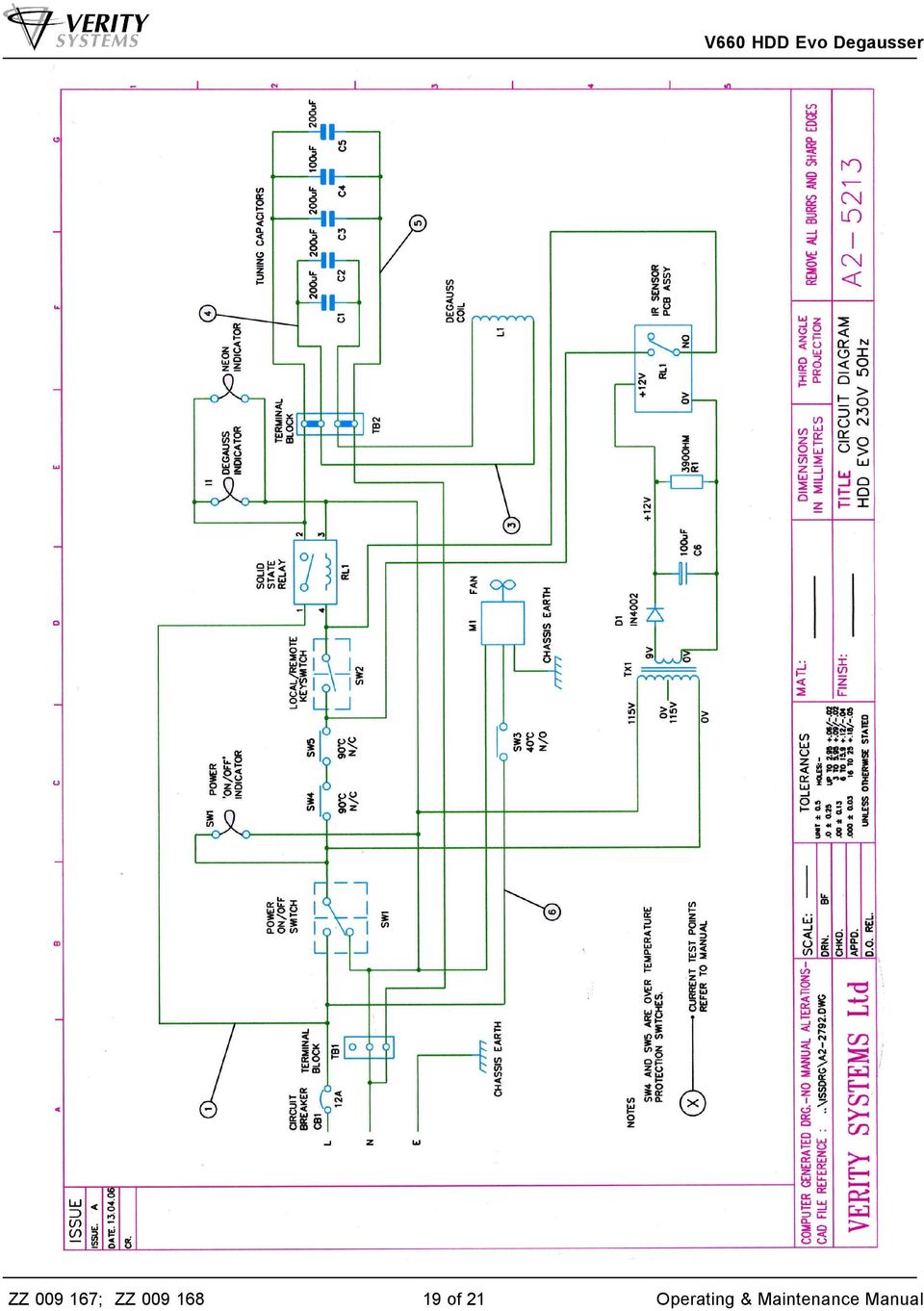
5 Table of Contents Cont d Appendix A Basic Fault Finding Table Appendix B Current Monitor Test Points 16 Appendix C Parts List Appendix D Circuit Diagrams of 21

6 SECTION 1: SPECIFICATION Hard Drives Erased 3½" PC Hard Disk Drives Power Requirements (factory set) ZZ ZZ Line Voltage: 220/240v 115v Line Frequency: 50Hz 60Hz Current (typical): 10A 14A Protection Circuit 12A 16A Erasure Time: 5 seconds typical Run Time: 10 minutes typical Duty cycle : Non-continuous. Average 10 minutes. Mounting: Free standing table top Overall Dimensions: Depth:19 inches (480mm) Width: 16.5 inches (420mm) Height: 6 inches (150mm) Weight: Approximately 77lbs/35kg 6 of 21
 Width: 16.")
7 SECTION 2: INTRODUCTION The V660 HDD Evo degausser functions like a large electro magnet, its erasing field originating as leakage flux from a large gap in the field structure, the V660 s structure is basically a U section. The field intensity decreases rapidly as the distance from the degausser surface increases. For example at a distance of approximately 2.75 inches from the degausser's surface a field strength of only 50 oersteds exists. Furthermore, the erasing field present at the front edge nearest the operator is also very low. Hard Disk Drives The vulnerability of information stored on PC hard drives is a recognised security risk. Unlike other PC data storage media the hard drive always stays with the PC. Every time a PC leaves a company s control all the data and company information will go with it. Even if the hard drive breaks down the storage platters will still contain information which could be read once repaired. In keeping with our policy of recognising user requirements we have introduced the V660 HDD Evo eraser. The V660 HDD Evo is capable of removing data from PC hard drives in less than 5 seconds. Although in most cases this will render the hard drive inoperative, the cost of a replacement hard drive cannot be compared to the cost to a company if sensitive information can be read by a third party. 7 of 21

8 SECTION 3: INSTALLATION 3.1 Unpacking Unpack the degausser carefully, and verify that all parts are present. If there are missing or damaged parts contact Verity Systems or an authorised partner/reseller immediately to correct any miss-packed or missing parts. You should find the following : Verity Systems V660 HDD Evo degausser Infrared remote control switch Power cable This user manual 3.2 Power Requirements Check the power supply requirements on the label attached to the back of the equipment with the available supply. The unit is supplied with a flying 3 wire cable which, when connected to a properly wired receptacle, earths the unit. It is essential that a proper earth connection is made to assure safe operation. Caution! A good electrical ground must be connected to the degausser. The unit must be connected to the correct power supply. Failure to do so may result in permanent damage. Connections Wire Colour 50 Hz 60 Hz Brown Live Hot Blue Neutral Cold Yellow/Green Earth Ground IMPORTANT INSTRUCTION The mains supply outlet socket should be close to the installed equipment and fully accessible. Note: Degausser Current Consumption The degaussing coils are powered as part of a tuned resonant circuit. This allows quite high circulating currents to be generated within the degaussing coils, with minimal current consumption from the mains voltage supply. However, this technique requires that the waveform of the supply voltage contains minimal harmonic distortion. A distorted waveform will result in an increase in current consumption. In extreme cases excessive current will trip the circuit breaker making it necessary to use a mains filter to remove the distortion and reduce the current consumption. 8 of 21

9 The typical current consumption figures provided in this manual are when powered from a supply with minimal distortion. Any increase in current consumption due to a distorted waveform will have minimal effect on the degausser performance, however, excessive current consumption should be avoided for obvious reasons. In the event of unexplained high currents, please consult your supplier. SECTION 4: OPERATION WARNING! STRONG MAGNETIC FIELDS ARE GENERATED. REMOVE WATCHES BEFORE USE ENSURE THAT THE FAN OPERATES CORRECTLY DURING USE. (AFTER INITIAL WARM UP PERIOD). OPERATING PERIODS IN EXCESS OF SPECIFIED DURATION WILL RESULT IN EXTERIOR SURFACES BECOMING VERY HOT. The V660 HDD Evo has been designed for simplicity of operation and erases hard disk drives in a single operation. The V660 HDD Evo can be operated locally or remotely via the infrared control Because of the different types and manufactures specifications of PC hard disk units, Verity Systems only recommends the erasure of hard disk units as a security precaution for the following. a. Erasure of data from a faulty disk pack before being sent for service/repair. b. Erasure of data from disk packs before disposal of computer equipment. Note: Verity Systems cannot guarantee that a drive will be operational after degaussing. 4.1 Erasure of Hard Drives Locally 1. With the red power switch off, lift the lid on the top of the degausser. 2. Place the hard disk drive into the foam receptacle. 3. Close the lid 4. Ensure the key switch is in the upright position indicating LOCAL operation (see image A). 5. Press the red POWER switch Note: The illuminating on/off power switch is of the latching push button type which energises the degaussing coil. 6. The yellow DEGAUSS indicator light will illuminate. 7. After 5 seconds, press the red POWER switch to stop erasure 8. Remove the erased hard disk drive Image A 9 of 21
.")
10 4.2 Erasure of Hard Disk Drives Remotely 1. Ensure the key switch is turned 90 degrees clockwise indicating REMOTE operation (see image B). 2. With the unit switch on, lift the lid on the top of the degausser. 3. Place the hard disk drive into the foam receptacle. 4. Close the lid. 5. Point the remote control at remote control sensor on the degausser (see diagram C) and hold down the large button on the control. 6. The yellow DEGAUSS indicator light will illuminate. 7. After 5 seconds, release the button on the remote control to stop erasure. 8. Remove the erased hard disk drive. 9. Switch unit off Image B Image C 10 of 21

11 SECTION 5: INDICATORS/FEATURES 5.1 Indicator The degauss indicator (large yellow button) is provided to give an indication of degausser coil energisation. Certain circumstances can arise when, although the unit is switched on, the degauss coils may not be energised. 5.2 Warning indicator The field failure indicator is provided to give further reassurance that the degauss field is present. The indicator is considered more reliable being a red LED. 5.3 IR Transmitter The infrared transmitter LED illuminates when the remote control is in operation. 5.4 Overheat Protection The high energy field developed by the V660 HDD Evo necessitates the generation of a considerable amount of heat. The degausser coil is monitored for excessively high temperatures and should this condition occur its operation will be inhibited until the coil has cooled sufficiently. 5.5 Cooling A thermostatically controlled cooling fan is provided to extend the operating period to a maximum. 5.6 Protection The unit is protected by a thermal type circuit breaker. The current rating depends on the specified operating voltage. Infrared Sensor Degauss Indicator Lights Remote/Local Operation Key Switch Local Degauss On/Off Button IR Transmitter 11 of 21

12 SECTION 6: MAINTENANCE/SERVICING The unit is basically maintenance free but periodic checks should be made to ensure the correct operation of the fan and the good condition of the power cable. Note: To reduce the risk of shock hazard, disconnect the degausser from the mains voltage supply before carrying out any maintenance or servicing. 6.1 Circuit Breaker To reset the circuit breaker simply 'push in' and 'release' the button. 6.2 Bulb Replacement Note: Remove Power from the unit before replacing bulbs Remove the "bulb lens" from the "switch/indicator body" by levering it forwards. Neon Voltage Model Power Switch Indicator ZZ v v ZZ v v Remove the bulb from the rear of the "bulb housing" using a suitable extraction tool Replace the bulb noting the following: Note: The bulb will fit in only one position in a locating slot. If when fitting this does not occur, remove the bulb and rotate it through Refit the "bulb lens" to the "switch/indicator body" gently pushing the lens into the "switch/ indicator body" housing. 12 of 21

13 6.3 Cooling Fan The cooling fan is of the conventional axial type powered from the ac voltage supply. The unit is over temperature and over current protected and does not require servicing. However in the event of failure the fan may easily be replaced from the rear of the degausser. 6.4 Internal Components Most of the internal components are replaceable, i.e. the solid state relay, toroidal transformer (60Hz only) and the thermal switches mounted on the degausser coil. However the tuning capacitors and the degaussing coil are not spared items and if found to be faulty the unit should be returned to Verity Systems for repair. To access the components inside the degausser the laminate cover must be removed. This entails breaking the adhesive seal using a sharp blade Solid State Relay Replacement A thermally conductive compound should be used to ensure adequate heat dissipation from the relay to the metal case Thermal Switch Replacement Care must be exercised when replacing either of the switches on the degausser coil. The switches are fitted using an epoxy resin and it is recommended that the new switch be fitted in a new position on the coil and the old switch be left in place. The wire connections are of the 'push on' spade type and are easily transferred to the new switch. A high temperature epoxy resin part no. EA should be used to secure the new switch Cover replacement The laminate cover should be cleaned of old adhesive before refitting, using the sealant part no. EA and high temperature tape, Part No. HS SECTION 7: TECHNICAL SUPPORT You should first attempt to get technical assistance from your dealer or authorised partner/reseller. Verity Systems support personnel can be reached at: Verity Systems Ltd. Verity Systems, Inc. 2 Eastern Road 5441 Merchant Circle, Unit A Aldershot Placerville Hampshire CA GU12 4TD United States United Kingdom Toll Free: (800) Tel: +44 (0) Tel: (530) Fax: +44 (0) Fax: (530) [email protected] [email protected] 13 of 21

14 APPENDIX A BASIC FAULT TABLE The table assists fault finding down to component levels. However, should the degaussing coil or tuning capacitors be found to be faulty it is recommended that the unit be returned to Verity Systems for repair. Function Symptoms Possible Fault Location Fails to erase drive and Circuit Breaker CB1 repeatedly tripped Incorrect supply voltage.frequency Faulty degauss coil L1 and /or tuning capacitors C1-C4 Power Lamp Fails to illuminate Loss of mains supply. User source Inside centre, left hand side User source Degauss lamp & Warning Lamp Fails to illuminate Tripped circuit breaker Faulty switch Faulty Neon Extensive use of degausser caused overheating. Allow unit to cool (not a fault). Faulty neon Faulty solid state relay R1 Faulty thermal switch SW2 Rear panel Front panel Front panel Front panel Inside on right hand side Inside on front end of degaussing coil Faulty transformer TX1 (115v 60 Hz only) Cooling Fan Fails to Operate Faulty thermal switch SW3 Faulty Fan M1 Inside front on left hand side Inside on front end of degaussing coil Rear Panel 14 of 21

15 Note: Degausser Current Consumption The degaussing coils are powered as part of a tuned resonant circuit. This allows quite high circulating currents to be generated within the degaussing coils, with minimal current consumption from the mains voltage supply. However, this technique requires that the waveform of the supply voltage contains minimal harmonic distortion. A distorted waveform will result in an increase in current consumption. The typical current consumption figures provided in this manual are when powered from a supply with minimal distortion. Any increase in current consumption due to a distorted waveform will have minimal effect on the degausser performance, however, excessive current consumption should be avoided for obvious reasons. In the event of unexplained high currents, please consult your supplier. 15 of 21

16 APPENDIX B: CURRENT MONITOR TEST POINTS The following table contains typical current values to be measured at specific points in the equipment. The values given are in amperes and may differ slightly from those actually measured due to component tolerance plus effects due to operating temperature. Model Voltage/Frequency Current Monitor Test Points ZZ ZZ v-240v 50 Hz 115v 60 Hz 10 N/A of 21

17 APPENDIX C: PARTS LIST ZZ (115V 60Hz) Designation Part No. Quantity Description CA Cable gland 16mm TB2 CG Terminal Block TB2 CG End Cover TB2 CG Jump Bar TB1 CM Terminal Block FM Guard 120mm metal M1 FM Fan 120mm HS Feet Ind 1 OI Neon SW1 OI Neon RL1 RS Relay SW3 SW Temperature Sensor SW2 SW Thermal Switch CB1 SW Circuit Breaker 16A SW1 SW Red lens SW1 SW Switch Body SW1 SW Switch Contacts IND1 SW Yellow Lens IND1 SW Indicator Body IND1 SW Dummy Socket TX1 TX Auto Toroid Transformer XX Fan Plate SW2 SW Mode Key Switch Ind2 OI Led Indicator R1 RP ohm Resistor RL2 XX IR Sensor D1 SD Rectifier Diode TX1 TX Transformer C6 CC µf Capacitor XX Fixed top XX Hinged lid XX IR Transmitter V660 HDD Evo Degausser 17 of 21

18 PARTS LIST ZZ ( V 50Hz) Designation Part No. Quantity Description CA Cable gland 16mm TB2 CG Terminal Block TB2 CG End Cover TB2 CG Jump Bar TB1 CM Terminal Block FM Guard 120mm metal M1 FM Fan 120mm HS Feet SW1 & Ind 1 OI Neon RL1 RS Relay SW3 SW Temperature Sensor SW2 SW Thermal Switch CB1 SW Circuit Breaker 12A SW1 SW Red lens SW1 SW Switch Body SW1 SW Switch Contacts IND1 SW Yellow Lens IND1 SW Indicator Body IND1 SW Dummy Socket XX Fan Plate SW4 SW Mode Key Switch Ind2 OI Led Indicator R1 RP ohm Resistor RL2 Xx IR Sensor D1 SD Rectifier Diode TX1 TX Transformer C6 CC µf Capacitor L1 MP Filter XX Fixed Top XX Hinged Lid XX IR Transmitter 18 of 21

19 19 of 21
20 20 of 21

21 Supplied by: Verity Systems Ltd. Verity Systems, Inc. 2 Eastern Road 5441 Merchant Circle, Unit A Aldershot Placerville Hampshire CA GU12 4TD United States United Kingdom Toll Free: (800) Tel: +44 (0) Tel: (530) Fax: +44 (0) Fax: (530) [email protected] [email protected]
TECHNICAL MANUAL. Operating and Maintenance Instructions for. Manual Degausser
 TECHNICAL MANUAL Operating and Maintenance Instructions for DIGI TAPEMASTER Manual Degausser DIGI TAPEMASTER TECHNICAL MANUAL Document No. M000263 Production Standard ZZ 009 154 ZZ 009 157 WARNING This
V94 BULK TAPE DEGAUSSER
 TECHNICAL MANUAL Operating and Maintenance Instructions for V94 BULK TAPE DEGAUSSER V94 BULK TAPE DEGAUSSER TECHNICAL MANUAL Document No. M000208 Production Standard ZZ 009 415 WARNING To help minimise
Security Approved Degausser
 SV91M Security Approved Degausser OPERATING and MAINTENANCE MANUAL 1 Thank you for purchasing a Verity Systems SV91M BULK TAPE DEGAUSSER OPERATING AND MAINTENANCE MANUAL Document Reference No. M000304
Vertical Display and Storage B1350-2. SKOPE Gen2: Three Door Chiller
 Vertical Display and Storage User Manual MAN1227 Rev. 3.0 March 2008 edition CONTACT ADDRESSES Designed and Manufactured by New Zealand SKOPE INDUSTRIES LIMITED PO Box 1091, Christchurch New Zealand Freephone:
Portable Air Conditioner. OWNER S MANUAL Read these instructions before use. Model: MF08CESWW. Voltage rating: 115V~60Hz Power rating : 800W
 MODE ALARM Portable Air Conditioner OWNER S MANUAL Read these instructions before use 8 Model: MF08CESWW Voltage rating: 115V~60Hz Power rating : 800W Customer Support : 1-800-474-2147 For product inquiries
USER INSTRUCTIONS FOR GET PORTABLE 12k BTU AIR CONDITIONER MODEL No. GPACU12HR
 USER INSTRUCTIONS FOR GET PORTABLE 12k BTU AIR CONDITIONER MODEL No. GPACU12HR CONTENTS Introduction Safety Notes Identification of parts Installation instructions Operation instructions Maintenance Troubleshooting
Installation and User Instructions Unvented Electric Storage Water Heater Models: S10UNV, S15UNV.
 Installation and User Instructions Unvented Electric Storage Water Heater Models: S10UNV, S15UNV. MULTIPOINT Please read and understand these instructions before starting work. Please leave this leaflet
How To Use A Power Supply Unit (Upu)
") BRAVER UPS (Uninterruptible Power System) User s Manual Safety CAUTION! This UPS utilizes voltages that may be hazardous. Do not attempt to disassemble the unit. The unit contains no user replaceable parts.
BRAVER UPS (Uninterruptible Power System) User s Manual Safety CAUTION! This UPS utilizes voltages that may be hazardous. Do not attempt to disassemble the unit. The unit contains no user replaceable parts.
SHOWER WATER HEATER MODEL BS 35 / 45 / 60 BS 35 E / 45 E / 60 E OPERATION AND INSTALLATION INSTRUCTIONS
 SHOWER WATER HEATER MODEL BS 35 / 45 / 60 BS 35 E / 45 E / 60 E OPERATION AND INSTALLATION INSTRUCTIONS 2 This water heater must be installed (water and electrical installation), commissioned and serviced
SERVICE MANUAL REFRIGERATION
 SERVICE MANUAL REFRIGERATION ELECTROLUX HOME PRODUCTS S.p.A. Publication no. Spares Operations Italy 599 36 16-90 Corso Lino Zanussi, 30 031117 I - 33080 PORCIA / PN (ITALY) ITZ/SERVICE/AA Fax +39 0434
Speedflow Undersink Unvented Water Heater. Models SF10K and SF15K. Instruction Manual
 Speedflow Undersink Unvented Water Heater Models SF10K and SF15K Instruction Manual Version 2.0 May 2009 Hyco SpeedFLOW UnVENTED WATER HEATER Models SF10K (10 Litres) and SF15K (15 Litres) 1. Introduction
INFRARED QUARTZ WALL HEATER
 INFRARED QUARTZ WALL HEATER MODEL NO: IQ2000 PART NO: 6939004 MOUNTING & OPERATION INSTRUCTIONS GC0715 INTRODUCTION Thank you for purchasing this CLARKE Infrared Wall Heater. Before attempting to use this
Oil and Coolant Circulating Heating System. Model - OCSM
 Oil and Coolant Circulating Heating System Model - OCSM Installation & Operation Manual 216280-000 REV 2 Identifying Your System The HOTSTART heating system is designed to heat fluids for use in marine
Single Channel Loop Detector
 Single Channel Loop Detector Model - LD100 Series The LD100 is a single channel inductive loop detector designed for parking and access control applications. The detector is connected to an inductive loop
IMPORTANT INSTRUCTIONS & OPERATING MANUAL. Houston 50 Inch Electric Wall Mounted Fireplace Black / White
 IMPORTANT INSTRUCTIONS & OPERATING MANUAL Houston 50 Inch Electric Wall Mounted Fireplace Black / White Model Number:MFE5050BK Model Number:MFE5050WH Read these instructions carefully before attempting
Online UPS. PowerWalker VFI 1000R/1U
 Online UPS PowerWalker VFI 1000R/1U Manual Uninterruptible Power Supply System Table of Contents 1. Important Safety Warning... 1 1-1. Transportation... 1 1-2. Preparation... 1 1-3. Installation... 1 1-4.
StorTrends 3400 Hardware Guide for Onsite Support
 StorTrends 3400 Hardware Guide for Onsite Support MAN-3400-SS 11/21/2012 Copyright 1985-2012 American Megatrends, Inc. All rights reserved. American Megatrends, Inc. 5555 Oakbrook Parkway, Building 200
User's Instructions. Alpha HE CB25/33 and HE SY25
 User's Instructions Alpha HE CB25/33 and HE SY25 Wall Mounted, Fan Assisted, Room Sealed, Gas Fired, High Efficiency Condensing Boiler Range For Technical help or for Service call... ALPHA HELPLINE Tel:
CR9971 2 Band Auto Set Dual Alarm Clock Radio ROBERTS. Sound for Generations. Please read this manual before use
 ROBERTS Sound for Generations CR9971 2 Band Auto Set Dual Alarm Clock Radio Please read this manual before use Contents Contents... 1 Controls...2-5 Switching on... 6 Setting the time manually... 6 Setting
Portable Air Conditioner. OWNER S MANUAL Read these instructions before use. Model: MM14CCS. Voltage rating: 115V~60Hz Power rating : 1400W
 Portable Air Conditioner OWNER S MANUAL Read these instructions before use Model: MM14CCS Customer Support : 1-800-474-2147 Voltage rating: 115V~60Hz Power rating : 1400W For product inquiries or support
ML 3320/3321. English. Read Me First SEL SEL MENU SHIFT TOF FF/LOAD EXIT GROUP ITEM SET PRINT POWER ALARM MENU TEAR PARK
 MENU SHIFT TOF ML 3320/3321 HSD NLQ CHARACTER PITCH UTL SSD 10 12 15 17 20 PROP Every effort has been made to ensure that the information in this document is complete, accurate, and up-to-date. Oki assumes
Name of Equipment Silver King Model SKMCD1P/C1. This equipment chapter is to be inserted in the appropriate section of the Equipment Manual.
 Name of Equipment Silver King Model SKMCD1P/C1 This equipment chapter is to be inserted in the appropriate section of the Equipment Manual. Manufactured exclusively for McDonald s By Silver King Refrigeration,
Installation and User Instructions Aquarius Undersink Vented Water Heaters Models: AU7/3, AU7/1, AU10/3, AU10/1.
 Installation and User Instructions Aquarius Undersink Vented Water Heaters Models: AU7/3, AU7/1, AU10/3, AU10/1. Please read and understand these instructions before starting work. Please leave this leaflet
AN500T, AN1000, AN1000T, AN1500, AN1500T AN2000, AN2000T
 Product Instruction Manual Accona AN500T, AN1000, AN1000T, AN1500, AN1500T AN2000, AN2000T Panel heater v16.5/5 Version 3.2 Jan 2015 Contents 1. Important safety points 2. Installation 2.1. Wall mounting
Service manual. Website: www.andico.com.au CAUTION - BEFORE SERVICING THE UNIT, READ THE SAFETY - PRECAUTIONS IN THIS MANUAL.
 Website: www.andico.com.au Service manual CAUTION - BEFORE SERVICING THE UNIT, READ THE SAFETY - PRECAUTIONS IN THIS MANUAL. - ONLY FOR AUTHORISED SERVICE PERSONNEL. MODELS: MPK1-09CR-QB8 MPK1-12ER-QB6
Portable Air Conditioner. OWNER S MANUAL Read these instructions before use. Model: MN12CES / MN10CESWW
 Portable Air Conditioner OWNER S MANUAL Read these instructions before use 8 Model: MN12CES / MN10CESWW Voltage rating: 120V~60Hz Power rating : 1100W (MN12CES) Power rating : 900W (MN10CESWW) Customer
TECHNICAL DATA & SERVICE MANUAL SPLIT SYSTEM AIR CONDITIONER INDOOR UNIT: AW52AL AW64AL AW52AL 387030095 AW64AL 0.8180.463.0 07/05
 TECHNICAL DATA & SERVICE MANUAL INDOOR UNIT: AW52AL AW64AL SPLIT SYSTEM AIR CONDITIONER Model No. Product Code No. AW52AL 387030095 AW64AL 387030096 0.8180.463.0 07/05 IMPORTANT! Please read before installation
Bubble King. User Manual
 Bubble King User Manual TABLE OF CONTENTS 1. Before You Begin... 3 What Is Included... 3 Unpacking Instructions... 3 Claims... 3 Text Conventions... 3 Icons... 3 Document Information... 3 Product at a
Floodlight Range Installation Guide
 SPARTAN Floodlight Range Installation Guide CML13ATEX3007 IEC Ex CML14.0001 This installation guide provides instructions for installing the Infra-Red and White-Light SPARTAN SPX series of explosion protected
USER S MANUAL HSC-24A
 AIRREX AIR CONDITIONER USER S MANUAL HSC-24A Thank you for purchasing an AIRREX AIR CONDITIONER. BEFORE operation please read this user s manual carefully. Keep this manual readily available. It is ESSENTIAL
Hot Water Urns. all models. Helpline. v3.0
 Hot Water Urns all models Helpline 01384 573999 instructions.indd 1 v3.0 02/06/2014 14:50 IMPORTANT INFORMATION - RETAIN FOR FUTURE USE When using any electrical appliance, basic safety precautions should
LUCCI AIRFUSION QUEST II CEILING FAN
 LUCCI AIRFUSION QUEST II CEILING FAN WITH IR REMOTE INSTALLATION OPERATION MAINTENANCE WARRANTY INFORMATION CAUTION READ INSTRUCTIONS CAREFULLY FOR SAFE INSTALLATION AND FAN OPERATION. V1.0 QUEST II IR
Current valve. for AC 24 V pulse/pause control of electrical loads up to 30 kw
 4 937 DESIO Current valve for AC 24 V pulse/pause control of electrical loads up to 30 kw SEA45.1 Use The current valve is used for the control of electric heating elements in heating, ventilation and
TABLE OF CONTENTS. Hurricane 1300 User Manual 2 Rev. 4
 User Manual TABLE OF CONTENTS 1. BEFORE YOU BEGIN... 3 What Is Included... 3 Unpacking Instructions... 3 Claims... 3 Product at a Glance... 3 Safety Instructions... 4 2. INTRODUCTION... 5 Product Overview...
COLOR VIDEO DOOR PHONE CDV-71BE/D
 COLOR VIDEO DOOR PHONE CDV-71BE/D 513-11, Sangdaewon-dong, Jungwon-gu, Seongnam-si, Gyeonggi-do, Korea Int l Business Dept. : Tel.; +82-31-7393-540~550 Fax.; +82-31-745-2133 Web site : www.commax.com Printed
User s Manual AURORA 1.2K/2.2K
 User s Manual AURORA 1.2K/2.2K Uninterruptible Power System Safety CAUTION This UPS utilizes voltages that may be hazardous. Do not attempt to disassemble the unit. The unit contains no user serviceable
Outdoor 33.6W Dual Port Passive Power-over-Ethernet Midspan For External Security Cameras and Wireless Access Points
 Outdoor 33.6W Dual Port Passive Power-over-Ethernet Midspan For External Security Cameras and Wireless Access Points Features SELV Compliant No Detection Passive Injector Gigabit Compatible Full Protection
10000HXL31/15000HXL31/20000HXL31
 Table of Contents www.eaton.com/dxups USER MANUAL ON LINE UPS 10000HXL31/15000HXL31/20000HXL31 Uninterruptible Power Supply Table of Contents 1. Brief introduction 1.1 System and model description---------------------------------------------------------------------1
Portable Air Conditioner
 Portable Air Conditioner Owner's Manual Model:3 in 1 12,000 Btu/h Series 3 Please read this owner s manual carefully before operation and retain it for future reference. CONTENTS 1. SUMMARY...1 2. PORTABLE
TMS TANK MANAGEMENT SYSTEM
 TMS TANK MANAGEMENT SYSTEM Page 1 of 9 Operating Instructions GENERAL The Tank Management System is a bespoke design to control, monitor and accommodate efficient storage and dispensing of TMS. FUNCTIONS
SUB Universal water baths SBB Boiling baths JB, PB Unstirred water baths
 SUB Universal water baths SBB Boiling baths JB, PB Unstirred water baths Operating instructions Universal water baths SUB6: 6 litres SUB14: 14 litres SUB28: 28 litres SUB36: 36 litres Boiling baths SBB6:
Daker DK 1, 2, 3 kva. Manuel d installation Installation manual. Part. LE05334AC-07/13-01 GF
 Daker DK 1, 2, 3 kva Manuel d installation Installation manual Part. LE05334AC-07/13-01 GF Daker DK 1, 2, 3 kva Index 1 Introduction 24 2 Conditions of use 24 3 LCD Panel 25 4 Installation 28 5 UPS communicator
Heat Surge Model X5C Fire Place Insert Service Manual Applies to all units w/30000208 circuit board
 Heat Surge Model X5C Fire Place Insert Service Manual Applies to all units w/30000208 circuit board 2012 HS M4417A BR16597R-1 HEAT SURGE 8000 FREEDOM AVE, N. CANTON, OH 44720 330-244-8161 WWW.HEATSURGE.COM
www.sebury.com.cn Digital Keypad Use s Manual
 K3 K4 www.sebury.com.cn Digital Keypad Use s Manual Contents Introduction Introduction Specifications Intramural Interface Circuit 3 Mounting 3 Wiring 5 Power UP 7 Engineer Programming Mode 7 The K3/K4
543-0032-00, 943-0032-00. User s Manual
 543-0032-00, 943-0032-00 User s Manual 1 Comfort Alert Diagnostics Faster Service And Improved Accuracy The Comfort Alert diagnostics module is a breakthrough innovation for troubleshooting heat pump and
USER S MANUAL. MaxPower 400-600 UPS. Uninterruptible Power System 28-2MAXPO0018
 USER S MANUAL MaxPower 400-600 UPS Uninterruptible Power System 28-2MAXPO0018 IMPORTANT SAFETY INSTRUCTIONS SAVE THESE INSTRUCTIONS This manual contains important instructions for models MaxPower 400 and
NEWTECH PRO 1-2-3 KVA ONLINE UNINTERRUPTIBLE POWER SUPPLY USER MANUAL
 NEWTECH PRO 1-2-3 KVA ONLINE UNINTERRUPTIBLE POWER SUPPLY USER MANUAL [email protected] / www.tuncmatik.com Table of Contents 1. Important Safety Warning 2 1-1. Transportation 2 1-2. Preparation 2 1-3.
WARMER or COOKER/WARMER
 WARMER or COOKER/WARMER Use & Care Manual FW-S500 WARMER 3138365 Conforms to: UL STD: 197 3138365 Conforms to: NSF STD.4 FW-S600 COOKER / WARMER Model Description Size Voltage Hz Wattage FW-S500 Electric
RI-215A Operator s Manual. Part Number: 71-0045RK Revision 0 Released: 10/3/05
 RI-215A Operator s Manual Part Number: 71-0045RK Revision 0 Released: 10/3/05 Warranty RKI Instruments, Inc., warrants gas alarm equipment sold by us to be free from defects in materials and workmanship,
3 IN 1 BATHROOM HEATER
 3 IN 1 BATHROOM HEATER MODEL NO.: A515 - SH MINI FUNCTION: HEATER, EXHAUST FAN AND LIGHT Dear customers, Thank you for selecting the AUPU 3 in 1 Bathroom Heater. Please read all instructions before commencing
REB 1 REB 3 REB 5 REB 6 REB 8 REB 10 REB 12 REB 16
 REB 1 REB 3 REB 5 REB 6 REB 8 REB 10 REB 12 REB 16 Manually Operated Electronic Speed Controller Single Phase For all applications using suitably specified single-phase induction motor fans 1 GENERAL The
Roof Top Air Conditioner INSTALLATION AND OPERATING INSTRUCTIONS
 Roof Top Air Conditioner INSTALLATION AND OPERATING INSTRUCTIONS Ducted System RECORD THIS UNIT INFORMATION FOR FUTURE REFERENCE: Model Number: Serial Number: Date Purchased: This manual must be read and
Contact Details. Please note that some of the contact details on this PDF document may not be current.
 Contact Details Please note that some of the contact details on this PDF document may not be current. Please use the following details if you need to contact us: Telephone: 0844 879 3588 Email: [email protected]
Cooktop Low-Profile Ventilation Hoods
 INSTALLATION GUIDE Cooktop Low-Profile Ventilation Hoods Contents Wolf Cooktop Low-Profile Ventilation Hoods........ 3 Cooktop Low-Profile Hood Specifications.......... 4 Cooktop Low-Profile Hood Installation............
Triac Printed Circuit Board Replacement
 Technical Service Bulletin: Triac Printed Circuit Board Replacement TRONIC 5000C Pro Models: WH17, WH27, WH36 Introduction Fig. 1 ELECTRICITY IS EXTREMELY DANGEROUS. TAKE EXTRA PRECAUTIONS AND ENSURE ALL
Bathroom Cabinet. Installation & User Guide. Illuminated Mirrors. www.illuminated-mirrors.uk.com
 Illuminated Mirrors The UK s Largest LED Mirror Supplier to Trade and Retail Installation & User Guide Bathroom Cabinet www.illuminated-mirrors.uk.com Bathroom Cabinet Installation & User Guide Thank you
MOUNTING AND OPERATING INSTRUCTIONS
 MOUNTING AND OPERATING INSTRUCTIONS CF 51/55 1. Delivery CF 51/55-1 calculator with battery (optionally with mains power supply) - 1 wall mounting bracket - package with material for sealing, screws, wall
TECHNICAL SERVICE DEPARTMENT Technical Service Bulletin 1-800-432-8373. Tankless Electric (RTE) Troubleshooting
 Troubleshooting") Sequence of Operations 1 Power supply and field wiring block 2 Energy Cut Off (ECO) 3 Water flow plunger and cold inlet 4 Magnetic flow switch 5 Water temperature thermistor 6 Control panel and circuit
Sequence of Operations 1 Power supply and field wiring block 2 Energy Cut Off (ECO) 3 Water flow plunger and cold inlet 4 Magnetic flow switch 5 Water temperature thermistor 6 Control panel and circuit
33.6W Power over Ethernet Waterproof Adapter PoE Plus Single Port Injector for Outdoor Application
 33.6W Power over Ethernet Waterproof Adapter PoE Plus Single Port Injector for Outdoor Application Features Compliant with the IEEE802.3at Standard -40 to +60 C Temperature Range Diagnostic LEDs Full Protection
EKOS Cart. Instructions for Use
 EKOS Cart Instructions for Use EKOS Corporation 11911 North Creek Parkway South Bothell, WA 98011 USA (425) 415-3100 (tel) (425) 415-3102 (fax) [email protected] (e-mail) - 1-4913-002 REV E Intended Use
TECHNICAL MANUAL. Operating and Maintenance Instructions for DATAGAUSS LG AND DATAGAUSS XL-LG HARD DRIVE DEGAUSSERS
 TECHNICAL MANUAL Operating and Maintenance Instructions for DATAGAUSS LG AND DATAGAUSS XL-LG HARD DRIVE DEGAUSSERS ZZ201207 / ZZ201208 / ZZ201209 / ZZ201211 / ZZ2001212 VS SECURITY PRODUCTS LTD DATAGAUSS
SF15K SF05KSS, SF10KSS
 Product Instruction Manual Speedflow SF05K, SF10K & SF15K SF05KSS, SF10KSS & SF15KSS Undersink unvented water heater V15.6/6 Version 3.2 Jan 2015 Thank you for purchasing a Hyco Speedflow unvented water
Wall-Mounting your HP computer. User Guide
 Wall-Mounting your HP computer User Guide The only warranties for Hewlett-Packard products and services are set forth in the express statements accompanying such products and services. Nothing herein should
User Manual 1K/2K/3K Online UPS
 User Manual 1K/2K/3K Online UPS Uninterruptible Power Supply System Table of Contents 1. Important Safety Warning... 1 1-1. Transportation... 1 1-2. Preparation... 1 1-3. Installation... 1 1-4. Operation...
ESP 120 M1, ESP 208 M1, ESP 240 M1, ESP 415 M1, ESP 277 M1, ESP 480 M1 and M1R variants. Installation instructions ESP M1/M1R mains protectors
 ESP 120 M1, ESP 208 M1, ESP 240 M1, ESP 415 M1, ESP 277 M1, ESP 480 M1 and M1R variants Installation instructions Contents Key points of installation Before installation Installation Installation check
Yaesu FT-736R PSU repair
 Yaesu FT-736R PSU repair Updated for DigiKey (North American) sources & data I gratefully acknowledge OZ1DB and his original repair documentation and DL7VHF for his schematic diagrams The built in AC/DC
SERVICE MANUAL 12VDC WALL THERMOSTAT AIR CONDITIONING SYSTEMS ROOFTOP UNITS ONLY
 SERVICE MANUAL 12VDC WALL THERMOSTAT AIR CONDITIONING SYSTEMS ROOFTOP UNITS ONLY! WARNING - SHOCK HAZARD! TO PREVENT THE POSSIBILITY OF SEVERE PERSONAL INJURY, DEATH, OR EQUIPMENT DAMAGE DUE TO ELECTRICAL
REGULINE 600VA / 1000VA REGULATOR USER MANUAL
 REGULINE 600VA / 1000VA REGULATOR USER MANUAL TUNÇMATİK REGULINE SERIES AUTOMATIC VOLTAGE REGULATOR Models: REGULINE 600VA / REGULINE 1000VA Principle of Operation Automatic Voltage Regulators regulate
SERVICE MANUAL SPLIT SYSTEM ROOM AIR CONDITIONER SHARP CORPORATION SHARP CORPORATION CONTENTS
 SERVICE MANUAL SPLIT SYSTEM ROOM AIR CONDITIONER INDOOR UNIT AH-129 AH-MP14 OUTDOOR UNIT AU-129 AU-MP14 CONTENTS SPECIFICATIONS...2 EXTERNAL DIMENSIONS...4 WIRING DIAGRAMS...5 ELECTRICAL PARTS...6 MICROCOMPUTER
ATS Overhead Table Shelf System INSTRUCTION MANUAL
 ATS Overhead Table Shelf System INSTRUCTION MANUAL ATS Overhead Table Shelf System Instruction Manual Warranty Newport Corporation warrants this product to be free of defects in material and workmanship
RE-3 : SOLID TOP RANGE RANGE TOP ONLY
 VULCAN ELECTRIC SOlid top oven range MODEL: RE-3 - SOLID TOP oven Range RE-3T - SOLID range top only ON CABINET BASE RE-3 : SOLID TOP RANGE Model Re-3T : Solid TOP RANGE TOP ONLY Index: General Data 2
Meaco 30L and Meaco 40L dehumidifier instruction manual
 Meaco 30L and Meaco 40L dehumidifier instruction manual Please read this instruction manual before using the dehumidifier and keep safe for future reference SAFETY INSTRUCTIONS PLEASE READ ALL INSTRUCTIONS
RDJ10RF/SET. Wireless room temperature controller with 24-hour time switch and LCD. Programmable, for heating systems
 3 072 RDJ10RF RCR10/433 Wireless room temperature controller with 24-hour time switch and LCD Programmable, for heating systems RDJ10RF/SET Operating modes: Automatic, Comfort, Energy Saving, and Frost
Bulb Replacement REPLACING BULBS WARNING
 Bulb Replacement REPLACING BULBS Check the operation of all exterior lamps before you drive the vehicle. Caution: Before attempting to replace a bulb, ensure that both the affected lamp and the vehicle's
Fundamentals of Power
 Fundamentals of Power Fundamentals of Power 2008 American Power Conversion Corporation. All rights reserved. All trademarks provided are the property of their respective owners. Learning Objectives At
WB/WBS 3, 4, 5, 7, 8, 11, 14, 30
 INSTRUCTION MANUAL FOR WB/WBS 3, 4, 5, 7, 8, 11, 14, 30 WATER BATH PLEASE READ THIS MANUAL CAREFULLY BEFORE OPERATION 3, Hagavish st. Israel 58817 Tel: 972 3 5595252, Fax: 972 3 5594529 [email protected]
IMPORTANT SAFETY INSTRUCTIONS WARNING READ AND SAVE THESE OPERATING AND SAFETY INSTRUCTIONS BEFORE USING THIS HEATER.
 THERMAWAVE CERAMIC HEATER Model HZ-850 Series Model HZ-860 Series IMPORTANT SAFETY INSTRUCTIONS WARNING READ AND SAVE THESE OPERATING AND SAFETY INSTRUCTIONS BEFORE USING THIS HEATER. Warning Failure to
User Manual THR840DUK Digital Thermostat
 User Manual THR840DUK Digital Thermostat 50051982-001 Rev. A WARNING: This product must be correctly installed and configured to work properly (see pages 12-24). If you are not experienced in wiring electrical
AIR-CONDITIONER SPLIT TYPE
 FILE NO. A08-016 SERVICE MANUAL AIR-CONDITIONER SPLIT TYPE RAS-M10PKVP-E, RAS-M13PKVP-E, RAS-M16PKVP-E, RAS-M18PKVP-E / RAS-M10PKVP-ND, RAS-M13PKVP-ND, RAS-M16PKVP-ND, RAS-M18PKVP-ND / RAS-3M26GAV-E1,
POWER WAVE 455M/STT & (CE)
") Illustration of Sub Assemblies Illustration of Sub Assemblies Illustration of Sub Assemblies Illustration of Sub Assemblies P-450 P-450 PARTS LIST FOR POWER WAVE 455M/STT & (CE) P-450-A P-450-A ILLUSTRATION
Illustration of Sub Assemblies Illustration of Sub Assemblies Illustration of Sub Assemblies Illustration of Sub Assemblies P-450 P-450 PARTS LIST FOR POWER WAVE 455M/STT & (CE) P-450-A P-450-A ILLUSTRATION
BD150 INDUSTRIAL DEHUMIDIFIER USER MANUAL
 BD150 INDUSTRIAL DEHUMIDIFIER USER MANUAL Drawing : - TPC337 Issue : - 2 Date : - 24/01/12 UNPACKING Thank you for deciding to purchase an EIPL Industrial dehumidifier. Like the many tens of thousands
INSTRUCTION MANUAL PLEASE READ ALL THE INSTRUCTIONS COMPLETELY BEFORE USE AND SAVE THIS MANUAL FOR FUTURE REFERENCE
 INSTRUCTION MANUAL PLEASE READ ALL THE INSTRUCTIONS COMPLETELY BEFORE USE AND SAVE THIS MANUAL FOR FUTURE REFERENCE m Before Use Please read IMPORTANT SAFETY INSTRUCTIONS on page 10 before use. It is important
GenStore Archive Cabinet
 GenStore Archive Cabinet Setup and Maintenance Manual Version A April 2014 Two GenStore Archives shown mounted on optional table stand. 2 Contents Getting Started... 4 Using this Manual...4 Safety Precautions...4
Manual for Fire Suppression & Methane Detection System
 Manual for Fire Suppression & Methane Detection System Fogmaker North America Post address: 150 Gordon Dr Exton, PA 19341 Delivery address: 150 Gordon Dr Exton, PA 19341 Tel: 610-265-3610 Fax: 610-265-8327
SunMaxx Solar Filling Station Operating Instructions
 SunMaxx Solar Filling Operating Instructions Content 1. Declaration of conformity... 2 2. Introduction... 2 3. Transportation and unpacking... 4 4. Mounting and commissioning... 5 5. End of operation...
Indoor coil is too warm in cooling mode or too cold in heating mode. Reversing valve or coil thermistor is faulty
 Codes Room Air Conditioner range: Indoor unit alarm s If timer lamp flashes for 1 second on, 1 second off, this indicates pre heating on the coil during heating mode and is not an error. If timer lamp
Doc. No: 412-121033 Issue: 1 Date: Aug 2014. BTT-02 card printer manual THERMAL TRANSFER CARD PRINTER BTT-02
 Date: Aug 2014 THERMAL TRANSFER CARD PRINTER BTT-02 TABLE OF CONTENTS Introduction... 3 System Contents and Initial Checks... 3 Installation... 4 Preparation of Installation Site... 4 Printer Connections...
Portable Air Conditioner. OWNER S MANUAL Read these instructions before use. Model: MM14CHCSCS
 Portable Air Conditioner OWNER S MANUAL Read these instructions before use Model: MM14CHCSCS Voltage rating: 120V~60Hz Power rating : 1400W(Cooling) Power rating : 1350W(Heating) Customer Support : 1-800-474-21477
FL ballasts Electronic dimming. PCA T5 BASIC lp Y II, 14 80 W BASIC T5
 T5 TC-L PCA T5 BASIC lp Y II, 1 80 W BASIC T5 Product description Processor-controlled ballast with y II inside Highest possible energy class CELMA EEI = A1 BAT 1 Noise-free precise control via DSI signal,
SERVICE SERVICE MANUAL FOR ALDE ELECTRICAL HEATER
 SERVIE SERVIE MNUL FOR LDE ELETRIL HETER 2737 2762 2763 ontents Page hap Title 3 1:0 Flow chart 4 2:0 bout the electrical heater 4 2:1 Technical data 4 3:0 General faultfinding 4 4:0 Faultfinding 4 4:1
TIG INVERTER INSTRUCTION MANUAL
 TIG INVERTER INSTRUCTION MANUAL Contents Warning General Description Block Diagram Main Parameters Circuit Diagram Installation and Operation Caution Maintenance Spare Parts List Troubleshooting 3 4 4
Operating instructions in the back. www.blackanddecker.co.uk PD1020L
 Operating instructions in the back www.blackanddecker.co.uk PD1020L 2 ENGLISH (Original instructions) Intended use Your Black & Decker Dustbuster handheld vacuum cleaner has been designed for vacuum cleaning
UV100A Ultraviolet Air Treatment System
 UV100A Ultraviolet Air Treatment System INSTALLATION INSTRUCTIONS APPLICATION When installed in forced air heating and cooling systems, the UV100A Ultraviolet Air Treatment System kills airborne microorganism
WIRELESS HOME ALARM SYSTEM (WHA1)
") WIRELESS HOME ALARM SYSTEM (WHA1) IMPORTANT : PLEASE READ THIS MANUAL CAREFULLY BEFORE ATTEMPTING TO INSTALL AND OPERATE THIS ALARM SYSTEM. SAFETY Please note: Before you start to install this alarm, we
WIRELESS HOME ALARM SYSTEM (WHA1) IMPORTANT : PLEASE READ THIS MANUAL CAREFULLY BEFORE ATTEMPTING TO INSTALL AND OPERATE THIS ALARM SYSTEM. SAFETY Please note: Before you start to install this alarm, we
Product Guide AC Voltage Control Devices. Guide Guide. Popular Variable Transformers and AC Power Supplies. www.stacoenergy.com
 Popular Variable Transformers and AC Power Supplies Product Guide AC Voltage Control Devices Guide Guide Your Tailored Power Solutions Provider TM Staco Energy Products Co. has been a leading manufacturer
User Manual. Video Doorphone CDV-1020AQ
 User Manual Video Doorphone CDV-1020AQ 513-11, Sangdaewon-dong, Jungwon-gu, Seongnam-si, Gyeonggi-do, Korea Int l Business Dept. Tel. : +82-31-7393-540~550 Fax. : +82-31-745-2133 Web site : www.commax.com
SECTION G2: CABLE PROCESSOR MODULE MAINTENANCE
 SECTION G2: CABLE PROCESSOR MODULE MAINTENANCE Cable Processor Module overview WARNING! When tipping the Cable Processor Module back, (after removing the toggle arm pin), use extreme caution not to drop
BARDIC. 4 & 8 Zone Fire Panels Zircon range. Data, installation, operation and maintenance. by Honeywell
 Data, installation, operation and maintenance 4 & 8 Zone Fire Panels Zircon range BARDIC by Honeywell LED flashing LED Continuous FAULT DISABLE/TEST Power General Fault Sounder Fault/ Disable System Fault
Master Time Clock MTC-200 MTC-400 MTC-600. Users Manual
 Master Time Clock MTC-200 MTC-400 MTC-600 Users Manual Toll Free (888)713-0373 Phone (972)987-4408 FAX (877)720-9291 www.midwest-time.com [email protected] TABLE OF CONTENTS TOPIC PAGE GENERAL DESCRIPTION