SERVICE MANUAL 12VDC WALL THERMOSTAT AIR CONDITIONING SYSTEMS ROOFTOP UNITS ONLY
|
|
|
- James Campbell
- 8 years ago
- Views:
Transcription
1 SERVICE MANUAL 12VDC WALL THERMOSTAT AIR CONDITIONING SYSTEMS ROOFTOP UNITS ONLY! WARNING - SHOCK HAZARD! TO PREVENT THE POSSIBILITY OF SEVERE PERSONAL INJURY, DEATH, OR EQUIPMENT DAMAGE DUE TO ELECTRICAL SHOCK, ALWAYS BE SURE THE POWER SUPPLY TO THE APPLIANCE IS DISCONNECTED BEFORE DOING ANY WORK ON THE APPLIANCE. THIS CAN NORMALLY BE ACCOMPLISHED BY SWITCHING THE BREAKER FOR THE AIR CONDITIONER TO OFF, DISCONNECTING ALL EXTERNAL ELECTRICAL CONNECTIONS AND CORDS, SWITCHING ON BOARD ELECTRICAL GENERATORS AND INVERTERS TO OFF, AND REMOVING THE CABLE FROM EACH POSITIVE TERMINAL ON ALL STORAGE AND STARTING BATTERIES. DANGER SOME DIAGNOSTIC TESTING MAY BE DONE ON ENERGIZED CIRCUITS. ELECTRICAL SHOCK CAN OCCUR IF NOT TESTED PROPERLY. TESTING TO BE DONE BY QUALIFIED TECHNICIANS ONLY The steps outlined in this manual are intended to guide the service technician through the process of correctly diagnosing a Coleman Mach series rooftop air conditioner with a remote wall thermostat control system. Page -1-

2 TABLE OF CONTENTS PAGE I. INTRODUCTION TO WALL THERMOSTATS... 3 II INTRODUCTION TO RELAYS... 5 HOW DO RELAYS FUNCTION... 5 III IV CHECKING CEILING PLENUMS WITH INDIVIDUAL RELAYS... 6 CHECKING CEILING PLENUMS WITH PRINTED CIRCUIT BOARDS... 8 CHECKING THE THERMOSTAT OPERATION... 9 CHECKING THE PRINTED CIRCUIT BOARD OPERATION V DIAGNOSTIC FLOW CHARTS VI WIRING DIAGRAMS Page -2-

3 I. INTRODUCTION TO WALL THERMOSTATS All of the air conditioning functions are controlled by the wall mounted thermostat. These thermostats utilize a 12 VDC electrical circuit which is supplied by the vehicle manufacture or the installer of the A/C unit. Most of the thermostats provided by Recreation Vehicle Products are combination (Heat / Cool) thermostats. These thermostats are capable of operating both the roof top air conditioner and any furnace with a 12 VDC control circuit. The Figures below list three of the most commonly found Coleman/RV Products Wall Mounted Thermostats for rooftop air conditioners (heat pumps excluded). These thermostats are listed in chronological order from the oldest to the newest. 1. Mechanical / By-Metal Thermostats Heating Anticipator 2.Electronic Thermostats 3.Electronic Digital Display Thermostats NOTE: ALL THREE OF THESE THERMOSTATS ARE COMPLETELY INTERCHANGEABLE. Thermostats are really nothing more than temperature controlled switches. When the need for Cooling or Heating exists the thermostat sends a 12VDC(+) signal to the control relays or a P.C. board which in turn energizes the air conditioner components or the furnace. (Note: Relays and P.C. boards will be further discussed later in lesson II). Page -3-

4 The following chart shows the different electrical connections made by the thermostat during operation. The chart below assumes12vdc(+) is supplied to thermostat Red wire R and that 12VDC(-) or ground is supplied to the Blue wire B at all times. Thermostat Operations Cool Mode Selected On Low Fan Cool Mode Selected On High Fan Heat Mode Selected On Any Fan Speed (Note: Furnace blower operates independently from sequencer or time delay in furnace) Fan Only Selected (Hi-Fan Only) Internal 12VDC(+) Connections Made Red R to Yellow Y and Gray GL Red R to Yellow Y and Green GH Red R to White W Red R to Green GH Note: When the auto cool mode is selected on the thermostat the fan cycles on and off with the compressor as needed. When the on cool mode has been selected the fan runs continuously and the compressor cycles on and off as needed. The following chart depicts thermostat wiring and the wiring destinations for air conditioners with control boxes containing Printed Circuit Boards. THERMOSTAT TERMINAL / WIRE R or RED B or BLUE Y or YELLOW GH or GREEN GL or GRAY CONTROL AND SUPPLY WIRING (OEM / VENDOR) ONE RED, (+) 12VDC SUPPLY WIRE TO THE THERMOSTAT TWO BLUE, ONE (-) 12VDC SUPPLY WIRE TO THE THERMOSTAT AND ONE BLUE WIRE TO CEILING ASSEMBLY / PLENUM ONE YELLOW, COMPRESSOR CONTROL WIRE TO CEILING ASSEMBLY / PLENUM ONE GREEN, HIGH FAN CONTROL WIRE TO CEILING ASSEMBLY / PLENUM ONE GRAY, LOW FAN CONTROL WIRE TO CEILING ASSEMBLY / PLENUM CEILING ASSEMBLY TERMINAL DESIGNATION N /A B Y GH GL W or WHITE ONE WHITE, 12VDC (+) FURNACE CONTROL WIRE FROM THE THERMOSTAT NOTE: The (W) White wire is not available on COOL ONLY thermostats. FURNACE NOTE: THE CONNECTING WIRES TO THE THERMOSTAT ARE PROVIDED BY THE VEHICLE MANUFACTURER OR INSTALLER. THESE O.E.M. OR VENDOR SUPPLIED WIRES MAY NOT BE COLOR CODED AS NOTED IN THE CHART ABOVE. THE GROUND WIRE MUST BE A ZERO 0" RESISTANCE GROUND. Page -4-
 Fan Only Selected (Hi-Fan Only) Internal 12VDC(+) Connections Made Red R to Yellow Y and Gray GL Red R to Yellow Y and Green GH Red R to White W Red R to Green GH Note: When the auto cool")
5 THERMOSTAT LOCATION Thermostats are very sensitive instruments. For accurate temperature control and comfort the following considerations for thermostat locations should be taken into account: 1. Locate the thermostat on an inside wall about five foot above the floor. Pick a dry area where air circulation is good. The thermostat should be mounted within a reasonable distance from the appliance the thermostat will control. This will assure a more accurate temperature relationship between the thermostat and the appliance the thermostat will control. 2. Do not install the thermostat where there are unusual heating conditions; such as direct sunlight, heat producing appliances (television, radio, wall lamp, etc.); or a furnace or air conditioner supply register. 3. Note: When installing or servicing these thermostats the technician should take all necessary precautions not to short any positive wire to ground. Permanent damage to the thermostat may occur. Make sure all connections are good and tight. Loose connections may cause relay chattering which leads to welded relay contacts on air conditioner printed circuit boards. II. INTRODUCTION TO RELAYS In the previous chapter on thermostats we learned the wall thermostat makes necessary connections that provide low voltage power to initiate all of the air conditioning or heating functions. There is one question left unanswered. How do we use this 12VDC power to operate a 115VAC appliance? THE ANSWER IS: We use relays or printed circuit boards with relays located on them. HOW DO RELAYS FUNCTION So what is a relay? A relay is defined as an electromagnetic mechanism moved by a small electrical current in a control circuit (12VDC in this case). How does this relay work? As this mechanism moves back and forth in the relay it will open or close a set of contacts capable of carrying high voltage and (115VAC in this case). All of our control circuit relays are normally open and the contacts close as power from the thermostat is applied. As shown in Figure 1. on the next page, the 115VAC power to the compressor is interrupted by a set of normally open contacts on the relay. In order for these contacts to close 12VDC must be applied by the wall thermostat to the relay coil. When the thermostat switch is placed in the cool position 12VDC(+) travels from the thermostat red wire to the thermostat yellow (Y) wire and then to the relay coil. When the coil is activated an electromagnet inside the relay will pull the contacts closed. The 115VAC will now operate the compressor until the thermostat opens or the system switch is turned to the off position. Figure 1. shows a very simplified control circuit for compressor operation only. The entire control circuit for the A/C / Heating system would include the rest of the thermostat functions and possibly 2 or 3 more relays. In addition to the compressor relay you would need a separate relay for Low Fan, one for High Fan, and possibly one for Heat, if a heat pump or electric heating element is used. Please refer to the previous lesson or use the chart below for proper wiring from the wall thermostat to each individual relay. Page -5-

6 Figure 1 III. CEILING PLENUMS WITH INDIVIDUAL RELAYS Recreational Vehicle Products built 2 types of ceiling assembly packages which incorporate individual relays for the air conditioner system functions. Line drawing examples of these two ceiling assembly types are shown in figures 2 and 3. Figure 2. Page -6-

7 Figure 3 The following charts depict the thermostat control wiring, ceiling assembly wiring destinations, and relay functions for air conditioners with control boxes containing individual relays & -726 SERIES, & 726 SERIES CEILING PLENUMS THERMOSTAT CEILING PLENUM WIRE* UNIT OPERATION Yellow (Y) Yellow Compressor relay Green (GH) Green High Fan relay Gray (GL) Gray Low Fan relay Blue (B) (12VDC-) Blue N/A White (W) White Furnace or Heat Element relay SERIES CEILING PLENUM THERMOSTAT CEILING PLENUM WIRE* UNIT OPERATION Yellow (Y) Black Compressor Green (GH) Green High Fan Gray (GL) Gray Low Fan Blue (B) (12VDC-) Blue N/A White (W) White Furnace or Heat Element relay. * The low voltage wiring connections for the these control systems are hard wired by the manufacturer or installer of the unit and they may not all use color coded wire as noted above. Note: If the heating system includes a gas fired furnace the thermostat white wire will energize the Page -7-
 Gray Low Fan Blue (B) (12VDC-) Blue N/A White (W) White Furnace or Heat Element relay.")
8 furnace control circuit, (Usually a time delay relay located at the furnace). IV. CEILING PLENUMS WITH PRINTED CIRCUIT BOARDS Most of the 7000 and 8000 series ceiling plenums built since 1992 have had Printed Circuit Boards instead of individual relays. Printed circuit boards are less costly and require less wiring. The Printed Circuit Boards all have relays mounted permanently on them. Even though the boards may look much more complicated they are very easy to troubleshoot. On the following pages you will find some visual aids that will help you trouble shoot these units without removing the thermostat or the air conditioner control box lid. Recreational Vehicle Products has and is building many ceiling assembly packages which use Printed Circuit Boards to control air conditioner system functions. Just like the individual relays, the Printed Circuit Board must receive a signal from the wall thermostat to operate. A common ducted ceiling assembly application is shown here in Figure 4. Figure 4 Page -8-

9 Note: In ducted applications similar to the one found in Figure 4, the Printed Circuit Board / Control Box Assembly is found mounted in the return air opening of the Air Conditioner. In some older applications the Printed Circuit Board / Control Box Assembly will be located in the center of the roof opening just above the return air grille. Figure 5 shows an exploded view of the Control Box Assembly Figure 5 CHECKING THE THERMOSTAT OPERATION The 12 Volt DC signal from the wall thermostat may be checked at the Low Voltage Terminal Strip (Figure 6) located externally on the ceiling plenum wiring box Figure 6. Low Voltage Terminal Strip Anytime the thermostat is placed in the FAN ONLY position you should be able to read 12VDC between terminals GH and B at the Low Voltage Terminal Strip (see figure 6). Anytime the thermostat is placed in the LOW COOL position you should be able to read 12VDC between terminals GL and B for the Low Fan, and between terminals Y and B for compressor operation. Page -9-
 located externally on the ceiling plenum wiring box Figure 6.")
10 Anytime the thermostat is placed in the HIGH COOL position you should be able to read 12VDC between terminals GH and B for the High Fan, and between terminals Y and B for Compressor operation. Note: Thermostat operation in the Heating Mode cannot be tested at the Ceiling Assembly Low Voltage Terminal Strip if the thermostat is operating a gas fired furnace. Note: The wall thermostat will be equipped with an optional Electric Heat / Gas Heat switch if the Recreational Vehicle is equipped with a Heat Pump or with an Electric Heating Element. In this case the Electric Heat Mode may be checked the Low Voltage Terminal Strip. In either case the Low Voltage Terminal Strip will have an additional terminal labeled W for electric heating operation. When Electric Heat is chosen at the thermostat you should be able to read 12VDC between terminals W and B. Please note, the W terminal is not shown on the Low Voltage Terminal Strip (Figure 6) or in the chart below because it is not tremendously common.. THERMOSTAT CEILING ASSEMBLY TERMINAL UNIT OPERATION Yellow (Y) (Y) Compressor Green (GH) (GH) High Fan Gray (GL) (GL) Low Fan Blue (B) (12VDC-) (B) N/A If you do not find voltage at the Ceiling Assembly Low Voltage Terminal Strip as described above the problem needs to be traced back to the thermostat or the vehicles low voltage wiring. CHECKING THE PRINTED CIRCUIT BOARD OPERATION Low voltage MUST be verified at the Low Voltage Terminal Strip as described earlier in this text or as noted in the chart below before preceding to the next step, or checking the Printed Circuit Board. In order to continue you must first verify the 115VAC power source to the Air Conditioner Control Box Assembly. If the 115VAC power source is NOT present, all of the Air Conditioner functions will be dead and power must be restored to continue. 115VAC power must be present to the Circuit Board if any one of the Air Conditioner functions are working. The operation of the printed circuit board may be checked at the High Voltage 9-Pin Connector (Figure 7) without removing the electric box lid. The chart below shows the 115VAC connections made by the Circuit Board to the High Voltage 9-Pin Connector THERMOSTAT CONNECTIONS 115VAC CONNECTIONS AT THE LOW VOLTAGE MADE BETWEEN TERMINALS TERMINAL STRIP AT THE 9 PIN CONNECTOR 12VDC at Y and B Terminals # 1 and # 3 12VDC at GH and B Terminals # 5 and # 9 12VDC at GL and B Terminals # 6 and # 9 Page -10-

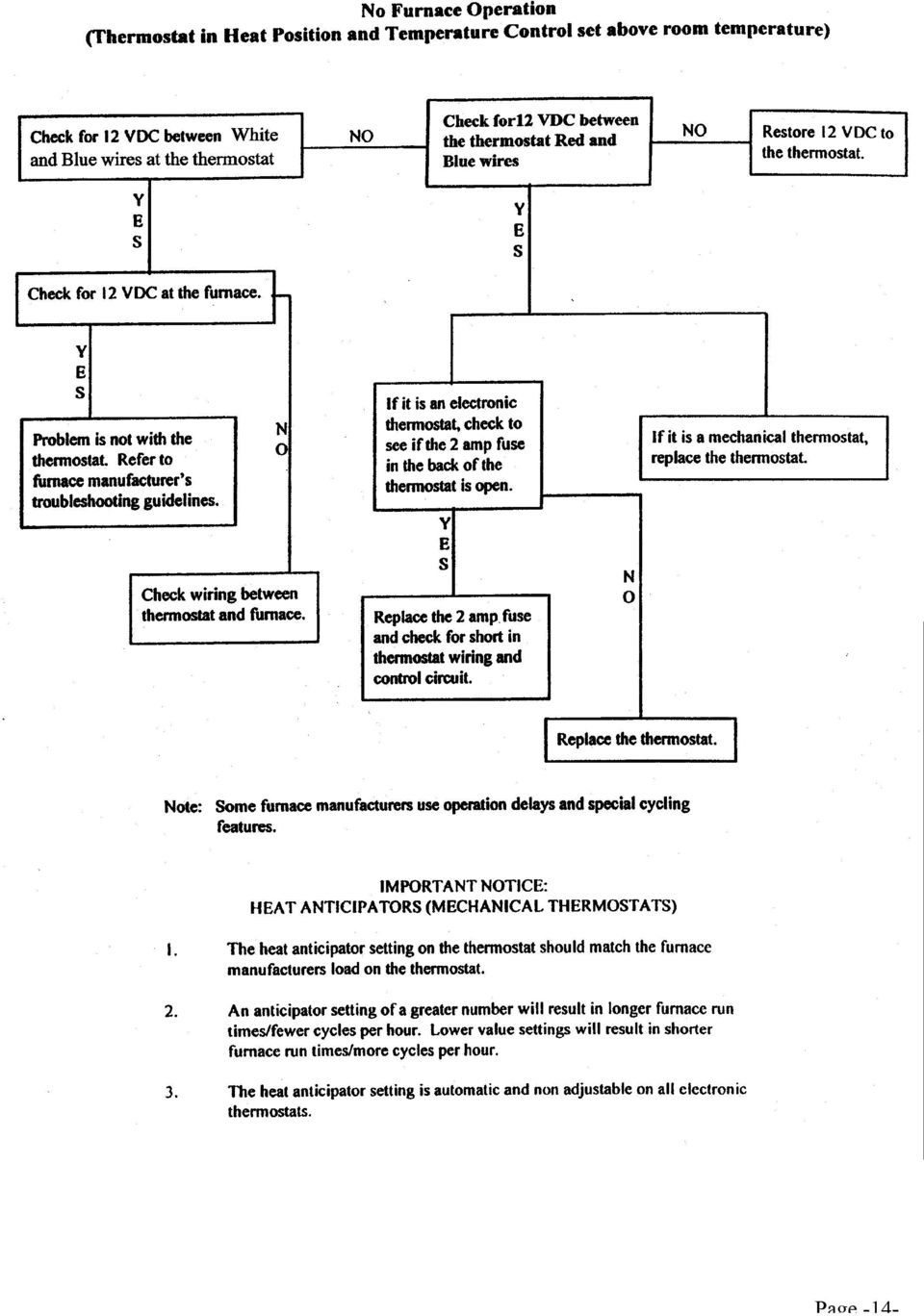
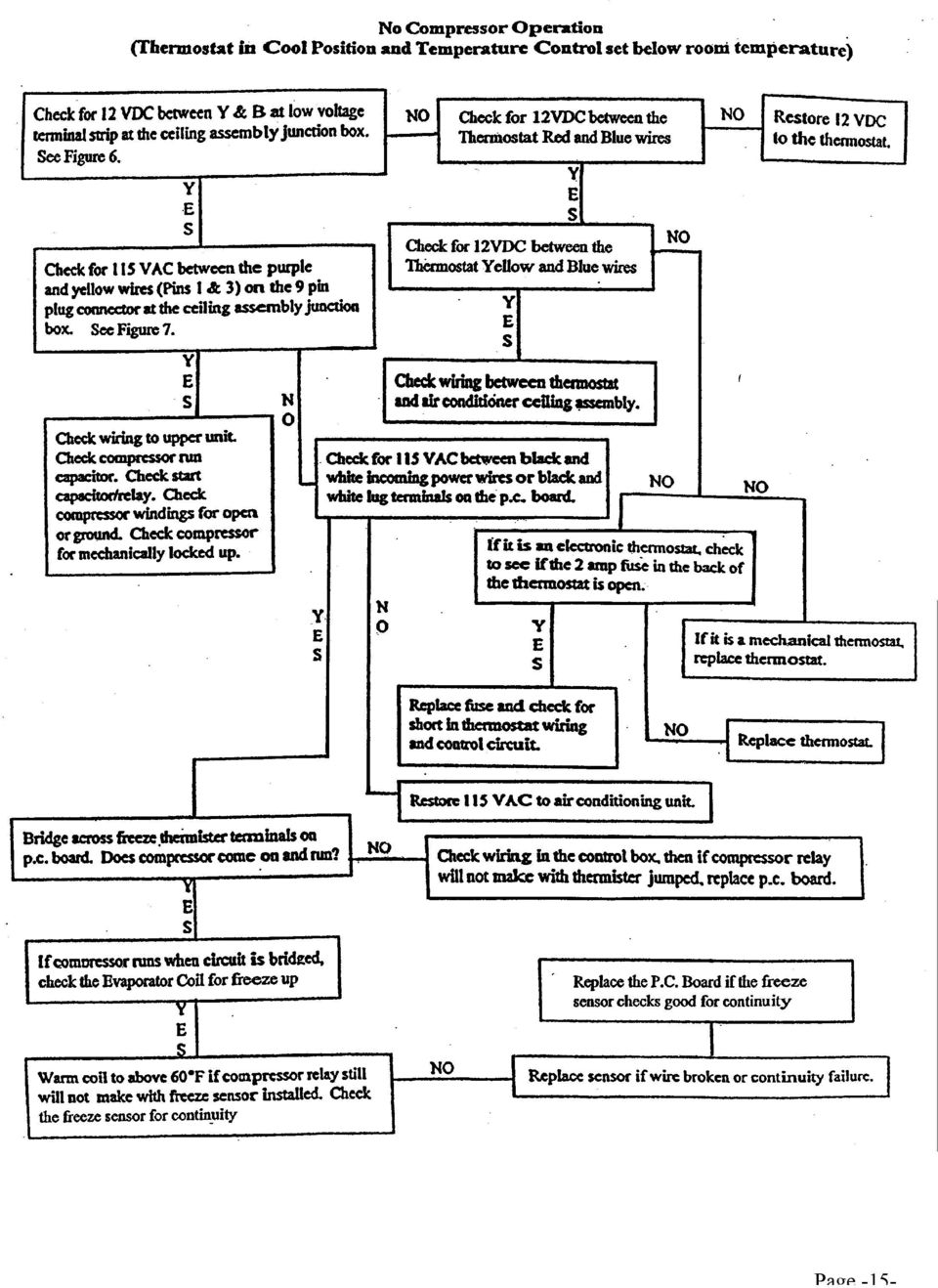
11 Figure 7. High Voltage 9-Pin Connector Note: To check voltage at the 9 pin connector plug it may be necessary to unplug the upper unit from the control box If the Air Conditioner is still not functioning and both 12VDC and 115VAC are present and accountable at their proper locations the problem is located in the upper unit. If the correct 115VAC connections are NOT made at the 9 pin connector plug after12vdc power is applied to the Low Voltage Terminal Strip; the problem is in the Printed Circuit Board with one exception as described below. The low temperature freeze thermistor could open the compressor relay on the Circuit Board if the Air Conditioner Evaporator Coil starts to freeze. If this switch is opens you would still have 12VDC at terminals Y and B, but no voltage would be present at terminals 1 and 3 in the High Voltage 9-Pin Connector. The Freeze Thermister opens if the evaporator coil temperature drops below 32 degrees and closes at 55 degrees. The probe end of this switch should be found pushed into the fins of the evaporator coil and the wires are hooked to the Printed Circuit Board. It is OK to remove the thermister wire from the Board and jump around these terminals fore diagnostic purposes. If the Air Conditioner compressor is running and NO VOLTAGE is found between terminals Y and B on the Low Voltage Terminal Strip the Printed Circuit Board must be replaced. The compressor relay has evidently welded shut. In conclusion, you can save a lot of time if you get in the habit of going immediately to the ducted control box assembly for trouble shooting purposes. There in a matter of minutes you can tell if the problem is in the Thermostat, the Printed Circuit Board, or the Upper Unit. V. DIAGNOSTIC FLOW CHARTS Note: When working with the following diagnostic flow charts, start at the top left corner and work towards the right or down the page as applicable. Do not skip around or start in middle without performing all prior steps. DANGER THE FOLLOWING DIAGNOSTIC TESTING WILL BE DONE ON ENERGIZED CIRCUITS. ELECTRICAL SHOCK CAN OCCUR IF NOT TESTED PROPERLY. TESTING TO BE DONE BY QUALIFIED TECHNICIANS ONLY Page -11-

12 Page -12-

13 Page -13-

14 Page -14-
15 Page -15-
16 VI. WIRING DIAGRAMS & Series Cool Only Ducted Ceiling Plenums , & Series Heat/ Cool Ducted Ceiling Plenums Page -16-

17 & Series Cool Only Remote Free Delivery Ceiling Plenums , & Series Heat/Cool Remote Free Delivery Ceiling Plenums Page -17-

18 (4-02) RV Products A Division of Airxcel, Inc. P.O. Box 4020 Wichita, KS Page -18-

SERVICE MANUAL FOR 12 VDC WALL THERMOSTAT AIR CONDITIONING SYSTEMS ROOF TOP UNITS ONLY
 RV Products Division SERVICE MANUAL FOR 12 VDC WALL THERMOSTAT AIR CONDITIONING SYSTEMS ROOF TOP UNITS ONLY Airxcel, Inc. RV Products Division P.O. Box 4020 Wichita, KS 67204 1976A376 (1-11) TABLE OF CONTENTS
SERVICE MANUAL FOR 6535 SERIES TWO TON HIGH EFFICIENCY PACKAGED HEAT PUMPS
 SERVICE MANUAL FOR 6535 SERIES TWO TON HIGH EFFICIENCY PACKAGED HEAT PUMPS TABLE OF CONTENTS 1. Warnings...2 2. Accessibility Of Appliance...3 3. Unit Dimensions And Specifications...3 4. Unit Specifications
Roof Top Air Conditioner INSTALLATION AND OPERATING INSTRUCTIONS
 Roof Top Air Conditioner INSTALLATION AND OPERATING INSTRUCTIONS Ducted System RECORD THIS UNIT INFORMATION FOR FUTURE REFERENCE: Model Number: Serial Number: Date Purchased: This manual must be read and
Air Conditioning Sign-Off Sheet
 Air Conditioning Sign-Off Sheet Printed Technician Name Address Social Security Number Telephone Number City State Zip Code Install Or Verify The Accuracy Of An Air Conditioner s Installation The candidate
Installation Questions
 Installation Questions How do I determine what type of heat I have? There may be several ways to determine what type of heat you have. First, if you can access the unit that is responsible for creating
Installation Instructions
 H5HK Series Installation Instructions 3 Phase Electric Heater Kits 7.5 and 0 TON Package A/C Systems Description Installation of 08/40V and 480V H5HK 3 Phase Heater Kits in 7.5 and 0 TON Packaged Air Conditioners.
543-0032-00, 943-0032-00. User s Manual
 543-0032-00, 943-0032-00 User s Manual 1 Comfort Alert Diagnostics Faster Service And Improved Accuracy The Comfort Alert diagnostics module is a breakthrough innovation for troubleshooting heat pump and
INSTALLATION & SERVICE MANUAL. Display Panel
 INSTALLATION & SERVICE MANUAL Display Panel The PowerLine EMS TM is a specialized power distribution and energy management system intended to be used in recreational vehicles. The Control Module is housed
Thermostatic Wiring Principles by Bob Scaringe Ph.D., P.E.
 Thermostatic Wiring Principles by Bob Scaringe Ph.D., P.E. Basic Thermostat Types Many technicians have great difficulty understanding how to properly wire a thermostat or how to replace a thermostat with
USER MANUAL WARNING! CONTENTS MODEL 1 SPECIFICATIONS READ ALL INSTRUCTIONS BEFORE PROCEEDING. Non-Programmable Single Stage Heat/Cool Thermostat
 Builder MODEL 1010 Series Non-Programmable Single Stage Heat/Cool Thermostat USER MANUAL Compatible with low voltage single stage gas, oil or electric heating or cooling systems, including single stage
Single Zone LCD Thermostat Operating Instructions
 Fan Cool Furnace *Heat Pump or Heat Strip On/Off F Single Zone LCD Thermostat Operating Instructions MODEL 3313192.XXX Cool/Furnace 3313193.XXX Cool/Furnace/Heat Pump 3313194.XXX Cool/Furnace/Heat Strip
EVANS ELECTRONIC TEMPERATURE CONTROL TROUBLESHOOTING GUIDE for systems equipped with electric coolant valve and external PC board.
 EVANS ELECTRONIC TEMPERATURE CONTROL TROUBLESHOOTING GUIDE for systems equipped with electric coolant valve and external PC board. This Troubleshooting Guide covers the electric coolant valve and control
INSTALLATION INSTRUCTIONS MC95HAE-1 MASTER CONTROLLER
 INSTALLATION INSTRUCTIONS MC95HAE-1 MASTER CONTROLLER Bard Manufacturing Company, Inc. Bryan, Ohio 43506 Since 1914...Moving ahead just as planned. Manual : 2100-360B Supersedes: 2100-360A File: Volume
Install Guide CT101. Caution. Caution
 Install Guide CT101 PG 1 Caution top cover Your thermostat is a precise instrument, handle it with care. Turn off electricity to the system before installing or servicing thermostat or any part of the
E2 Series Electric Furnaces
 E2 Series Electric Furnaces Service Manual Table of Contents Electrical Requirements... 10 Codes, Specifications Requirements... 10 Connection Supply Service Wires... 10 Furnace Sequence of Operation...
Install Guide CT100. Caution. Caution ENGLISH. disconnect the power supply before beginning work.
 Install Guide CT100 PG 1 Caution top cover Your thermostat is a precise instrument, handle it with care. Turn off electricity to the system before installing or servicing thermostat or any part of the
Failure code manual. content
 Failure code manual content 一 wall split AC series 2 二 floor standing AC series. 4 三 portable AC series.. 5 四 dehumidifer 6 五 DC inverter single split series...7 六 DC inverter multi-split series 10 1 一
USER INSTRUCTIONS FOR GET PORTABLE 12k BTU AIR CONDITIONER MODEL No. GPACU12HR
 USER INSTRUCTIONS FOR GET PORTABLE 12k BTU AIR CONDITIONER MODEL No. GPACU12HR CONTENTS Introduction Safety Notes Identification of parts Installation instructions Operation instructions Maintenance Troubleshooting
Transport Air Conditioning TRANSPORT AIR CONDITIONING OPERATOR S MANUAL. for SPLIT SYSTEM. Bus Air Conditioning Units.
 R Transport Air Conditioning TRANSPORT AIR CONDITIONING OPERATOR S MANUAL for SPLIT SYSTEM Bus Air Conditioning Units T--326 Rev -- OPERATOR S MANUAL BUS AIR CONDITIONING UNITS GEN IV & GEN V CONTENTS
USER S MANUAL HSC-24A
 AIRREX AIR CONDITIONER USER S MANUAL HSC-24A Thank you for purchasing an AIRREX AIR CONDITIONER. BEFORE operation please read this user s manual carefully. Keep this manual readily available. It is ESSENTIAL
Programmable Thermostat MODEL 3312026.XXX With Dehumidify 3312024.XXX With Out Dehumidify
 Comfort Control Center 2 Thermostat Operating Instructions Programmable Thermostat MODEL 3312026.XXX With Dehumidify 3312024.XXX With Out Dehumidify TABLE OF CONTENTS About your new thermostat Features...2
INSTRUCTION MANUAL FOR RECREATIONAL REFRIGERATOR/FREEZER MODEL
 INSTRUCTION MANUAL FOR RECREATIONAL REFRIGERATOR/FREEZER MODEL 15-LITER, 20-LITER, 35-LITER, 45-LITER, 60-LITER & 100-LITER SECTION 1 Basic Operation SECTION 2 Cleaning and Storing SECTION 3 Basic Trouble
Digi-Motor Installation Guide
 Digi-Motor Installation Guide Installation Video...located at marsdelivers.com Digi-Motor Installation Guide Digi-Motor For technical assistance with your Azure Digi-Motor, call the MARS technical support
 0150506194 C Limited 2nd through 5th Year Functional Parts Warranty During the 2nd through 5th year,haier will provide functional parts which prove to be defective due to workmanship
6. Diagnostics for A/C System Malfunction
 6. A: A/C OR SELF-DIAGNOSIS SYSTEMS DO NOT OPERATE TROUBLE SYMPTOM: Set temperature is not indicated on the display, switch LEDs are faulty or switches do not operate. Self-diagnosis system does not operate.
INSTALLATION INSTRUCTIONS COMMERCIAL ROOM VENTILATORS WITH EXHAUST
 INSTALLATION INSTRUCTIONS COMMERCIAL ROOM VENTILATORS WITH EXHAUST MODEL CHCRV-5 For Use with Bard CH Series 3, 4 & 5 Ton 2-Stage Wall Mount Heat Pumps AND W38H, W43H, W49H and W61H Single Stage Wall Mount
INSTALLER S & OWNER S MANUAL
 INSTALLER S & OWNER S MANUAL HVAC INSTALLER: PLEASE LEAVE MANUAL FOR HOMEOWNER DEH 3000 DEH 3000 Part No. 4028539 Dehumidifier & Ventilation System Controller P.O. Box 8680 Madison, WI 53708 TOLL-FREE
Installation and Operation Guide for PD5100 Automatic Transfer Switch
 Installation and Operation Guide for PD5100 Automatic Transfer Switch Member P r o gr e ssive Dynamics, Inc. 507 Industrial Rd Marshall, MI 49068 www.progressivedyn.com 2012 Progressive Dynamics, Inc.
R22. K Control. Indoor Unit. Nomenclature. Compatibility PL H 3 G K H B. Unit style Heat Pump Horse Power
 R22. K Control. Indoor Unit. Nomenclature. PL H 3 G K H B Compatibility Unit style Heat Pump Horse Power Control Boost Heaters R22. K Control. Outdoor Unit. Nomenclature. PU H 3 Y K A Compatibility Outdoor
Service manual. Website: www.andico.com.au CAUTION - BEFORE SERVICING THE UNIT, READ THE SAFETY - PRECAUTIONS IN THIS MANUAL.
 Website: www.andico.com.au Service manual CAUTION - BEFORE SERVICING THE UNIT, READ THE SAFETY - PRECAUTIONS IN THIS MANUAL. - ONLY FOR AUTHORISED SERVICE PERSONNEL. MODELS: MPK1-09CR-QB8 MPK1-12ER-QB6
Solar Home System. User Manual. AEH-SHS01-10W2L Solar Home System 2 Lamps
 Solar Home System User Manual AEHSHS0110W2L Solar Home System 2 Lamps All rights reserved Specifications subject to change without prior notice 2 Dear Customer, Thank you for purchasing Schneider Electric
SERVICE INSTRUCTION R410A. SPLIT TYPE ROOM AIR CONDITIONER Universal Floor / Ceiling Duct / Cassette Wall Mounted / Floor type INVERTER MULTI
 SERVICE INSTRUCTION SPLIT TYPE ROOM AIR CONDITIONER Universal Floor / Ceiling Duct / Cassette Wall Mounted / Floor type INVERTER MULTI R410A Models Indoor unit Outdoor unit AB*14LBAJ AB*18LBAJ AB*F14LAT
01-3 0000-00 6810-20 AIR CONDITIONING SYSTEM 1. FFH SPECIFICATION AIR CONDITIONING SYSTEM RODIUS 2004.09
 0000-00 01-3 6810-20 1. FFH SPECIFICATION 01-4 0000-00 2. SYSTEM LAYOUT AND COMPONENTS 0000-00 01-5 01-6 0000-00 3. FFH GENERAL INFORMATION The system is to increase the coolant temperature quickly by
BRISK AIR 579 Series, 590 Series, & 595 Series
 RECORD THIS UNIT INFORMATION FOR FUTURE REFERENCE: Model Number Serial Number Date Purchased USA SERVICE OFFICE The Dometic Corp. 509 So. Poplar St. LaGrange, IN 46761 (260) 463-4858 CANADA Dometic Dist.
INSTALLATION INSTRUCTIONS FOR INTERNATIONAL 9000 SERIES ROOF TOP AIR CONDITIONERS
 RV Products Division INSTALLATION INSTRUCTIONS FOR INTERNATIONAL 9000 SERIES ROOF TOP AIR CONDITIONERS Service Contact: Coast to Coast RV Services Pty Ltd. 20 George Young St. Auburn NSW 2144 Australia
SERVICE MANUAL. Room Air Conditioner Multi Split type Outdoor unit /R410A DC Inverter/
 SERVICE MANUAL Room Air Conditioner Multi Split type Outdoor unit /R410A DC Inverter/ FS2MI-147HFD FS2MI-187HFD FS3MI-217HFD FS3MI-277HFD FS4MI-277HFD FS4MI-367HFD FS5MI-367HFD NOTE: Before servicing the
AIR CONDITIONER & HEAT PUMP DIGITAL CONTROL FOR DUCTED SYSTEM INSTALLATION AND OPERATING INSTRUCTIONS
 AIR CONDITIONER & HEAT PUMP DIGITAL CONTROL FOR DUCTED SYSTEM INSTALLATION AND OPERATING INSTRUCTIONS FOR AC135, AC150, AC135HP, AC150HP, ACRG12, ACTH12 RECORD THIS UNIT INFORMATION FOR FUTURE REFERENCE:
Service Guide 12/27/03 TESTING, SERVICE & REPAIR GUIDE (For SH Space Heating Models & RA Water Heating Models)
") TESTING, SERVICE & REPAIR GUIDE (For SH Space Heating Models & RA Water Heating Models) WARNING - HIGH VOLTAGE AC electrical circuits are connected to this heater. Do not attempt any service work on the
TESTING, SERVICE & REPAIR GUIDE (For SH Space Heating Models & RA Water Heating Models) WARNING - HIGH VOLTAGE AC electrical circuits are connected to this heater. Do not attempt any service work on the
SERVICE MANUAL SPLIT SYSTEM ROOM AIR CONDITIONER SHARP CORPORATION SHARP CORPORATION CONTENTS
 SERVICE MANUAL SPLIT SYSTEM ROOM AIR CONDITIONER INDOOR UNIT AH-129 AH-MP14 OUTDOOR UNIT AU-129 AU-MP14 CONTENTS SPECIFICATIONS...2 EXTERNAL DIMENSIONS...4 WIRING DIAGRAMS...5 ELECTRICAL PARTS...6 MICROCOMPUTER
Air Conditioner Water Heater - A Product of HotSpot Energy LLC
 Air Conditioner Water Heater - A Product of HotSpot Energy LLC PLEASE READ THIS BEFORE YOU INSTALL THE UNIT 1. This air conditioner must be installed and/or repaired by a qualified technician. If you perform
Electronically Controlled Clutchless or Variable Drive Compressors
 Electronically Controlled Clutchless or Variable Drive Compressors On many new air conditioning systems, such as Lexus, Cadillac, Chrysler, and others, a new type of compressor has been fitted. There are
PUSH BUTTON START INSTALLATION MANUAL
 PUSH BUTTON START INSTALLATION MANUAL ALTHOUGH THIS PRODUCT HAS BEEN THOROUGHLY TESTED KPIERSON TECHNOLOGIES ASSUMES NO RESPONSIBILITY FOR ANY DAMAGE THAT MAY RESULT BY THE INSTALLATION OF THIS PRODUCT.
LG Air Conditioning Multi F(DX) Fault Codes Sheet. Multi Split Units
 Fault Codes Sheet. Multi Split Units") Multi Split Units If there is a fault on any LG Multi unit, an Error mark is indicated on the display window of the indoor unit, wired-remote controller, and LED s of outdoor unit control board. A two
Multi Split Units If there is a fault on any LG Multi unit, an Error mark is indicated on the display window of the indoor unit, wired-remote controller, and LED s of outdoor unit control board. A two
COLOR VIDEO DOOR PHONE CDV-71BE/D
 COLOR VIDEO DOOR PHONE CDV-71BE/D 513-11, Sangdaewon-dong, Jungwon-gu, Seongnam-si, Gyeonggi-do, Korea Int l Business Dept. : Tel.; +82-31-7393-540~550 Fax.; +82-31-745-2133 Web site : www.commax.com Printed
Si10-417_C. Pocket Manual. Service Diagnosis SPLIT & MULTI
 Pocket Manual Service Diagnosis SPLIT & MULTI Service Diagnosis SPLIT & MULTI 1. Troubleshooting with LED...5 1.1 Indoor Unit... 5 1.2 Outdoor Unit... 10 2. Troubleshooting by Symptoms...11 2.1 Air conditioner
ECM. Service Guide. www.thedealertoolbox.com
 ECM Service Guide www.thedealertoolbox.com ECM Table of Contents Service Guide Working on the motor with power connected may result in electrical shock or other conditions that may cause personal injury,
Pro Logic Version 4.10. Diagnostics Manual
 Pro Logic Version 4.10 Diagnostics Manual Turbo Cell & Control Electronics 2009 Hayward Industries Table of Contents Important safety instructions Pg. 1 No Cell Power 1 & No Cell Power 2 Pg. 2 No Cell
Portable Air Conditioner
 Portable Air Conditioner Owner's Manual Model:3 in 1 12,000 Btu/h Series 3 Please read this owner s manual carefully before operation and retain it for future reference. CONTENTS 1. SUMMARY...1 2. PORTABLE
ViZion Installation Guide
 ViZion Installation Guide v2.0 1 ViZion Installation Guide Table of Contents Inventory Hardware Setup Understanding Synchronization Cable Begin by taking an inventory of the required equipment DR Unit
Manual for Fire Suppression & Methane Detection System
 Manual for Fire Suppression & Methane Detection System Fogmaker North America Post address: 150 Gordon Dr Exton, PA 19341 Delivery address: 150 Gordon Dr Exton, PA 19341 Tel: 610-265-3610 Fax: 610-265-8327
FAQs. Conserve package. Gateway... 2 Range Extender... 3 Smart Plug... 3 Thermostat... 4 Website... 7 App and Mobile Devices... 7
 FAQs Conserve package Gateway... 2 Range Extender... 3 Smart Plug... 3 Thermostat... 4 Website... 7 App and Mobile Devices... 7 FAQs Gateway Can I have someone install my system for me? If you are concerned
Install Guide 3M-50. Caution. Caution
 PG 1 Install Guide 3M-50 aution Your thermostat is a precise instrument, handle it with care. Turn off electricity to the HVA system before installing or servicing thermostat or any part of the system.
WHOLESALE DIRECT INC. 5620 WEST 65TH STREET
 Auto Pump V 200 100 0 100 Max Rating Vehicle mount compressor ensures truck air brake system is properly pressurized for immediate dispatch from station Pressure switch regulated operation automatically
Advantium 2 Plus Alarm
 ADI 9510-B Advantium 2 Plus Alarm INSTALLATION AND OPERATING INSTRUCTIONS Carefully Read These Instructions Before Operating Carefully Read These Controls Corporation of America 1501 Harpers Road Virginia
Instruction Manual. 2in1 LAN Tester & Multimeter. Model: LA-1011
 Instruction Manual 2in1 LAN Tester & Multimeter Model: LA-1011 1 Contents Introduction... Features... Safety Precautions.. Meter Description... Electrical Specification... Operation.. AutoRanging Multimeter.
USER S, MAINTENANCE and SERVICE INFORMATION MANUAL
 CONTENTS SAFETY INFORMATION................ 2 FOR YOUR SAFETY....................... 2 SYSTEM OPERATION.................. 2 THERMOSTATS........................... 2 INTERMITTENT IGNITION DEVICE...........
SAFETY INSTRUCTIONS RECOGNIZE SAFETY INFORMATION
 RECORD THIS UNIT INFORMATION FOR FUTURE REFERENCE: Model Number Serial Number Date Purchased B3300 Series Roof Top Air Conditioner Used With Mechanical Air Distribution Box Kit 330978.004 This manual must
Portable Air Conditioner. OWNER S MANUAL Read these instructions before use. Model: MF08CESWW. Voltage rating: 115V~60Hz Power rating : 800W
 MODE ALARM Portable Air Conditioner OWNER S MANUAL Read these instructions before use 8 Model: MF08CESWW Voltage rating: 115V~60Hz Power rating : 800W Customer Support : 1-800-474-2147 For product inquiries
HM-W536 Install Guide
 HM-W536 Install Guide 9/13/2013 IMPORTANT SAFETY INSTRUCTIONS Warning - When using electrical devices, basic safety precautions should be followed to reduce the risk of fire, electrical shock or injury.
A/C-HEATER SYSTEM - AUTOMATIC
 A/C-HEATER SYSTEM - AUTOMATIC 1995 Volvo 850 1995-96 Auto. A/C-Heater Systems Volvo 850 * PLEASE READ THIS FIRST * WARNING: To avoid injury from accidental air bag deployment, read and carefully follow
Portable Air Conditioner. OWNER S MANUAL Read these instructions before use. Model: MN12CES / MN10CESWW
 Portable Air Conditioner OWNER S MANUAL Read these instructions before use 8 Model: MN12CES / MN10CESWW Voltage rating: 120V~60Hz Power rating : 1100W (MN12CES) Power rating : 900W (MN10CESWW) Customer
Circuit breaker panel. Power supply for condensing unit. Power supply for furnace. Air handler (Furnace)
") UNIT OBJECTIVES Describe the concept of year-round air conditioning List three typical year-round air conditioning system types List the five ways to condition the air Determine airflow for a cooling system
UNIT OBJECTIVES Describe the concept of year-round air conditioning List three typical year-round air conditioning system types List the five ways to condition the air Determine airflow for a cooling system
INSTALLATION AND OPERATION MANUAL
 RCS MODEL ZC4 4 ZONE HVAC INSTALLATION AND OPERATION MANUAL DCN: 141-0020-02 /0/03 INTRODUCTION The 4 Zone HVAC Controller series allows up to 4 standard electronic thermostats to independently control
DC400 Dispensing Cutoff System
 DC400 Dispensing Cutoff System DC404 and DC406 Installation Instructions Franklin Fueling Systems 3760 Marsh Rd. Madison, WI 53718 USA Tel: +1 608 838 8786 800 225 9787 Fax: +1 608 838 6433 www.franklinfueling.com
SERVICE INSTRUCTION R410A. WALL MOUNTEDtype INVERTER SPLIT TYPE ROOM AIR CONDITIONER. Models Indoor unit Outdoor unit
 SERVICE INSTRUCTION SPLIT TYPE ROOM AIR CONDITIONER WALL MOUNTEDtype INVERTER Models Indoor unit Outdoor unit ASYG07LECA ASYG09LECA ASYG12LECA ASYG14LECA AOYG07LEC AOYG09LEC AOYG12LEC AOYG14LEC R410A CONTENTS
Portable Air Conditioner. OWNER S MANUAL Read these instructions before use. Model: MM14CCS. Voltage rating: 115V~60Hz Power rating : 1400W
 Portable Air Conditioner OWNER S MANUAL Read these instructions before use Model: MM14CCS Customer Support : 1-800-474-2147 Voltage rating: 115V~60Hz Power rating : 1400W For product inquiries or support
General Information. Do programmable thermostats really save energy?
 General Information Do programmable thermostats really save energy? Yes, programmable thermostats can save energy which in turn saves you money on your utility bill. The US Department of Energy states
NO-FROST CUSTOMER SUPPORT INFORMATION INFORMATION ON THE NO-FROST TECHNOLOGY WHITE GOODS
 INFORMATION INFORMATION ON THE TECHNOLOGY The -Frost refrigerators are different from the other static refrigerators in terms of their operational system. In normal refrigerators, in the freezing section,the
THE CARE AND FEEDING OF YOUR RV IIl
 THE CARE AND FEEDING OF YOUR RV IIl Troubleshooting and Repair of Your Propane Equipment (Water Heaters, Furnaces & Refrigerators) by Howard Lefkowitz Airstream Tech Help Group WBCCI #6077 techhelp@wbcci.org
HOUSING QUALITY STANDARDS (HQS)
") HOUSING QUALITY STANDARDS (HQS) Series 5 Electrical Safety And INSPECTIONS 5.01 ELS Revised 8-17-06 Electricity is Dangerous All electrical repairs should be made by licensed professionals. Touching any
HOUSING QUALITY STANDARDS (HQS) Series 5 Electrical Safety And INSPECTIONS 5.01 ELS Revised 8-17-06 Electricity is Dangerous All electrical repairs should be made by licensed professionals. Touching any
ENERGY SMART TROUBLESHOOTING GUIDE TABLE OF CONTENTS:
 ENERGY SMART TROUBLESHOOTING GUIDE TABLE OF CONTENTS: COMPONENTS/BOARD LAYOUT... 2 HOT WATER... 3 1 FLASH (GREEN DIAGSTIC LIGHT)... 4 2 FLASHES (GREEN DIAGSTIC LIGHT)... 5 3 FLASHES (GREEN DIAGSTIC LIGHT)...
Rain+Birdt. Simple To Set Timer (SST) Setup & Operation Instructions. English. 1-800- RAIN BIRD (800-724-6247) or visit www.rainbird.
 Setup & Operation Instructions. English. 1-800- RAIN BIRD (800-724-6247) or visit www.rainbird.") Rain+Birdt Simple To Set r (SST) Setup & Operation Instructions English Installation...2 Tools and Supplies Needed...2 Step 1. Mount r...2 Step 2. Connect Power...2 Indoor r...2 Outdoor r...2 Step 3. Connect
Rain+Birdt Simple To Set r (SST) Setup & Operation Instructions English Installation...2 Tools and Supplies Needed...2 Step 1. Mount r...2 Step 2. Connect Power...2 Indoor r...2 Outdoor r...2 Step 3. Connect
REMOTE CONTROL MANUAL
 REMOTE CONTROL MANUAL ENGLISH CONTENT PRECAUTIONS...1-2 USING THE REMOTE CONTROL UNIT...3 OPERATION...4-9 Thank you for purchasing our Room Air Conditioner. Before using your air-conditioner, please read
i ChatterBox! Motorcycle Security
 i Before you Start the Installation * Please read this manual to become familiar with the requirements necessary to complete the installation. * Use a high quality multi-meter to test all wires before
SERVICE MANUAL. Room Air Conditioner Multi Split Wall-Mounted Type Indoor. FSAI-Pro-91AE2 FSAI-Pro-121AE2 FSAIF-Pro-181AE2
 SERVICE MANUAL Room Air Conditioner Multi Split Wall-Mounted Type Indoor FSAI-Pro-91AE2 FSAI-Pro-121AE2 FSAIF-Pro-181AE2 NOTE: Before servicing the unit, please read this at first. Always contact with
Installation/Operator Manual For use with WFCO ULTRA III Power Center Model WF-8712P and WF-8725P
 Installation/Operator Manual For use with WFCO ULTRA III Power Center Model WF-8712P and WF-8725P Distributed in the U.S.A. and Canada by CHENG USA, INC. Sales (574) 294-8997 Warranty Service (877) 294-8997
INSTALLER'S GUIDE. Supplementary Electric Heaters 18-GJ08D1-1. Table of Contents
 INSTALLER'S GUIDE ALL phases of this installation must comply with NATIONAL, STATE AND LOCAL CODES Models: BAYEAAC051A BAYEAAC05LG1A BAYEAAC081A BAYEAAC08LG1A BAYEAAC101A BAYEAAC10LG1A BAYEABC151A BAYEABC201A
INSTALLATION INSTRUCTIONS AIRCOMMAND IBIS ROOFTOP AIRCONDITIONER
 \ INSTALLATION INSTRUCTIONS AIRCOMMAND IBIS ROOFTOP AIRCONDITIONER Suitability: The IBIS caravan rooftop aircondioner is suitable for installation on caravans and motorhomes provided the roof structure
Heating, Ventilation, Air Conditioning and Refrigeration (HVACR)
") Heating, Ventilation, Air Conditioning and Refrigeration (HVACR) I. Demonstrate safety skills in typical HVACR work situations to NATE Core Installer Knowledge Areas for Technician Excellence for Safety
Heating, Ventilation, Air Conditioning and Refrigeration (HVACR) I. Demonstrate safety skills in typical HVACR work situations to NATE Core Installer Knowledge Areas for Technician Excellence for Safety
http://waterheatertimer.org/how-to-troubleshoot-gas-water-heater.html
 http://waterheatertimer.org/how-to-troubleshoot-gas-water-heater.html APPLY POWER TO APPLIANCE FIELD WIRING CORRECT? DPLAY ERROR CODE 1 OR 2 Intelli-Vent TM Sequence of Operation REQUEST FOR HEAT PRESENT?
Installation Manual. 24 VDC Rooftop Air Conditioner
 SeaMach 24 VDC Rooftop Air Conditioner Installation Manual 24 VDC Rooftop Air Conditioner Chapter 1: Safety Considerations... 2 Chapter 2: General Information... 3 Chapter 3: Air Conditioning Sizing...
SECTION 16720 - FIRE AND SMOKE ALARM SYSTEM. City of San Diego, CWP Guidelines
 PART 1 -- GENERAL 1.1 WORK OF THIS SECTION SECTION 16720 - City of San Diego, CWP Guidelines A. The WORK of this Section includes providing manual and automatic fire alarm and smoke detection systems meeting
Troubleshooting Guide, Freedom and Fleet Power Inverter/Chargers
 Technical Note Freedom/Fleet Power 512-0084-01-01 Rev 1 Troubleshooting Guide, Freedom and Fleet Power Inverter/Chargers Overview This document is a guide for troubleshooting inverters, battery chargers,
AIR CONDITIONER & HEAT PUMP SERVICE MANUAL
 AIR CONDITIONER & HEAT PUMP SERVICE MANUAL AL This Service Manual is the result of the dedication of The Dometic Corporation and its engineers to providing service people the necessary instructions for
TYPE. MODEL B3200 Roof-Top Air Conditioner used with Mechanical Air Distribution Box INSTALLATION & OPERATING INSTRUCTIONS. 3253.332 Air Conditioner
 Type 5. Installation and Operating Instructions RECORD THIS UNIT INFORMATION FOR FUTURE REFERENCE: Model Number Serial Number Date Purchased MODEL B00 Roof-Top Air Conditioner used with Mechanical Air
LG Air Conditioning - Universal Split Fault Codes Sheet. Universal Split Systems
 Universal Split Systems If there is a fault on any LG Universal unit, a two digit number will appear on the remote controllers led display. If the unit does not have a remote controller the fault will
TECHNICAL SUPPORT MANUAL 3 Phase Air Conditioner Component R2A3**GHR
 3 Phase Air Conditioner Component R2A3**GHR DANGER, WARNING, CAUTION, and NOTE The signal words DANGER, WARNING, CAU- TION, and NOTE are used to identify levels of hazard seriousness. The signal word DANGER
TECHNICAL SERVICE DEPARTMENT Technical Service Bulletin 1-800-432-8373. Tankless Electric (RTE) Troubleshooting
 Troubleshooting") Sequence of Operations 1 Power supply and field wiring block 2 Energy Cut Off (ECO) 3 Water flow plunger and cold inlet 4 Magnetic flow switch 5 Water temperature thermistor 6 Control panel and circuit
Sequence of Operations 1 Power supply and field wiring block 2 Energy Cut Off (ECO) 3 Water flow plunger and cold inlet 4 Magnetic flow switch 5 Water temperature thermistor 6 Control panel and circuit
TECHNICAL DATA & SERVICE MANUAL SPLIT SYSTEM AIR CONDITIONER INDOOR UNIT: AW52AL AW64AL AW52AL 387030095 AW64AL 0.8180.463.0 07/05
 TECHNICAL DATA & SERVICE MANUAL INDOOR UNIT: AW52AL AW64AL SPLIT SYSTEM AIR CONDITIONER Model No. Product Code No. AW52AL 387030095 AW64AL 387030096 0.8180.463.0 07/05 IMPORTANT! Please read before installation
User Manual Color video door phone
 User Manual Color video door phone CDV-70KM Thank you for purchasing COMMAX products. Please carefully read this User s Guide (in particular, precautions for safety) before using a product and follow instructions
Heat Surge Model X5C Fire Place Insert Service Manual Applies to all units w/30000208 circuit board
 Heat Surge Model X5C Fire Place Insert Service Manual Applies to all units w/30000208 circuit board 2012 HS M4417A BR16597R-1 HEAT SURGE 8000 FREEDOM AVE, N. CANTON, OH 44720 330-244-8161 WWW.HEATSURGE.COM
DORMA MODEL PS-406BB POWER SUPPLY INSTALLATION INSTRUCTIONS
 Features: INSTALLATION Install in accordance with NFPA 70. DORMA MODEL PS-406BB POWER SUPPLY INSTALLATION INSTRUCTIONS Up to 1.95 Amps Load Capacity Class 2 Rated Outputs Overload, Over Voltage, and Short
Roof Top Unit. Description Model Type Use With Air Distribution Box. Heat Pump B3200 3242 3311669.018 Integral Mechanical
 RECORD THIS UNIT INFORMATION FOR FUTURE REFERENCE: Type Number Product Number Serial Number ADB Number ADB Serial Number Date Purchased Roof Top Unit Description Model Type Use With Air Distribution Box
COLEMAN-MACH AIR CONDITIONER PARTS In Section Q: Atwood Coleman (RVP) Cooling Units Dometic Norcold Powerhouse Suburban Thetford Wedgewood X-Reference
 Cooling Units Dometic Norcold Powerhouse Suburban Thetford Wedgewood X-Reference") COLEMAN-MACH AIR CONDITIONER PARTS Blower Motor Impeller Relay Compressor Condensor Coil Fan Blade Ducted Printed Circuit Board Start Relay Filter Shroud Return Grill Ducted Thermostat Capacitors Decals
COLEMAN-MACH AIR CONDITIONER PARTS Blower Motor Impeller Relay Compressor Condensor Coil Fan Blade Ducted Printed Circuit Board Start Relay Filter Shroud Return Grill Ducted Thermostat Capacitors Decals
its ELECTRIC POSITION for electric heat, or set the units fan control appropriately to ELECTRIC or another appropriate setting.
 Troubleshooting Poor Temperature Regulation This page lists problems that may affect the temperature performance of your LUX thermostat with suggested resolutions. For more detailed information please
Technical Update TAA.TU.11093 Rev. 1
 http://www.gambro.com/en/usa_tech/ 800-525-2623 303-222-6500 Technical Update TAA.TU.11093 Rev. 1 Effective: 05 APR 2013 CO# 13084 Product: Subject: From: Phoenix Dialysis System Required Electrical Safety
How To Use A Sata Dsa Hard Disk Storage System
 EXTERNAL RAID STORAGE OF HDDS INSTRUCTION MANUAL CAUTION RISK OF ELECTRIC SHOCK CAUTION TO REDUCE THE RISK OF ELECTRIC SHOCK, DO NOT OPEN COVER. NO USER SERVICEABLE PARTS INSIDE. REFER SERVICING TO QUALIFIED
Air Conditioner 457915 B57915 459516 B59516 540315 540316 640312 640315
 RECORD THIS INFORMATION FOR FUTURE REFERENCE: Number Serial Number ADB Number ADB Serial Number Date Purchased USA SERVICE OFFICE Dometic Corporation 2320 Industrial Parkway Elkhart, IN 46516 CANADA Dometic
Technical Information
 Date of last update: Oct-11 Ref: D7.8.4/1011/E Application Engineering Europe CORESENSE DIAGNOSTICS FOR STREAM REFRIGERATION COMPRESSORS CoreSense Diagnostics for Stream Refrigeration Compressors... 1