The Application of Vector Network Analyzers in Balanced Transmission Line Signal Integrity Measurements
|
|
|
- Margaret Brooks
- 8 years ago
- Views:
Transcription
1 1 The Application of Vector Network Analyzers in Balanced Transmission Line Signal Integrity Measurements

2 Agenda 1. Introduction 1.1 The Application and Advantages of Balanced Transmission Lines 1.2 Important Parameters and Characteristics for Balanced Transmission Lines 1.3 Characteristic Impedance, Structural Return Loss (SRL), Attenuation, Delay, Skew, Near End Crosstalk (NEXT), Far End Crosstalk (FEXT) 1.4 Single Ended, Common Mode, Differential Mode, Mixed Mode Scattering Parameters (S Parameters), Mode Conversion 2. Techniques Used to Connect Vector Network Analyzers (VNA) to Balanced Transmission Lines 2.1 Use of Baluns to Transform a 50 Ohm Un-balanced VNA Test Port to 100 Ohm Balanced Transmission Line 2.2 Use of a Multiport VNA Test Set to Transform 50 Ohm Un-balanced VNA Test Ports to 100 Ohm Balanced Transmission Lines 2.3 Advantages and Limitations of Each Approach 3. Frequency Domain Measurements for Balanced Transmission Lines 3.1 Frequency Domain Measurement with a VNA 3.2 Frequency Domain Measurement with a TDR / TDT (FFT) 3.3 Advantages and Limitations of Each Approach 2
 to Balanced Transmission Lines 2.1 Use of Baluns to Transform a 50 Ohm Un-balanced VNA Test Port to 100 Ohm Balanced Transmission Line 2.")
3 Agenda 4. Time Domain Characteristics and Parameters for Balanced Transmission Lines 4.1 Characteristic Impedance, Fault Type and Location, Attenuation, Delay, Skew, Near End Crosstalk (NEXT), Far End Crosstalk (FEXT) 4.2 Single Ended, Differential Mode, Common Mode, Mixed Mode, Mode Conversion 4.3 Time Domain Measurement with a VNA (IFT) 4.4 Time Domain Measurement with a TDR / TDT 4.5 Advantages and Limitations of Each Approach 5. Techniques Used with MultiPort Vector Network Analyzers (VNA) for Balanced Transmission Line Measurements 5.1 Use of Mathmatical Superposition with a Single Source MultiPort VNA for Balanced Transmission Line Measurements 5.2 Use of Dual Differential Sources MultiPort VNA for Balanced Transmission Line Measurements 5.3 Advantages and Limitations of Each Approach 6. Fixture and Launch Considerations in Connecting to Balanced Structures 3
 for Balanced Transmission Line Measurements 5.")
4 Introduction What is Signal Integrity (SI)? An Engineering Practice That ensures all signals transmitted are received correctly That ensures signals don t interfere with one another in a way to degrade reception. That ensures signals don t damage any devices That ensures signals don t pollute the electromagnetic spectrum 4

5 Introduction Components of High Speed Design Transmitter Interconnect Receiver Transistors Sources Algorithms Passives Memory Circuit elements Transmission lines S parameter blocks Transistors Passives Algorithms Memory 5


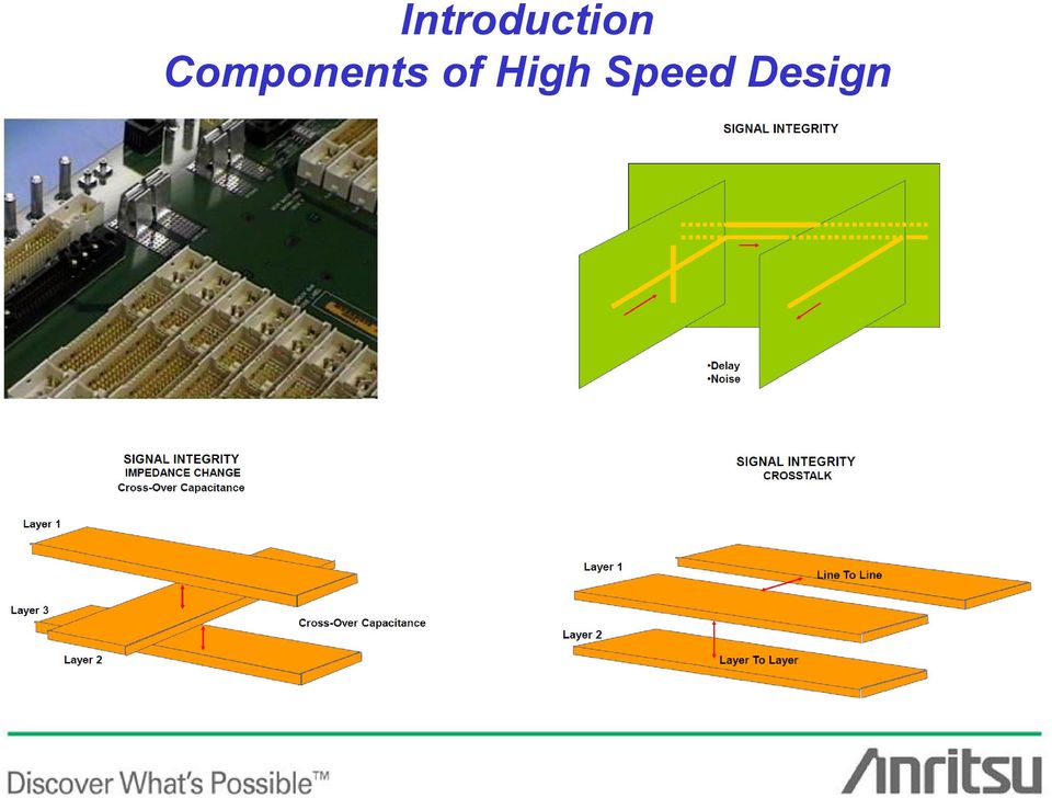
6 Introduction Components of High Speed Design 6


7 The Application and Advantages of Balanced Transmission Lines Shielded Quad Data Cable (Fiber-Channel) 7


8 The Application and Advantages of Balanced Transmission Lines 8

9 Important Parameters and Characteristics for Balanced Transmission Lines 9


10 Important Parameters and Characteristics for Balanced Transmission Lines 10

11 Important Parameters and Characteristics for Balanced Transmission Lines 11


12 Important Parameters and Characteristics for Balanced Transmission Lines 12

13 Important Parameters and Characteristics for Balanced Transmission Lines Propagation equation γ = ( R + jωl)( G+ jωc) = α+ jβ α is the attenuation (loss) factor β is the phase (velocity) factor Characteristic Impedance equation ( R+ jωl) Z0= ( G+ jωc) Propagation delay per unit length (T ( 0 ) {time/distance} [ps/in] Or Velocity (v ( 0 ) {distance/ time} [in/ps] Characteristic Impedance (Z ( 0 ) Per-unit unit-length Capacitance (C ( 0 ) [pf/in] Per-unit unit-length Inductance (L ( 0 ) [nf/in] Per-unit unit-length (Series) Resistance (R ( 0 ) [W/in] Per-unit unit-length (Parallel) Conductance (G ( 0 ) [S/in] 13
![{time/distance} [ps/in] Or Velocity (v ( 0 ) {distance/ time} [in/ps] Characteristic Impedance (Z ( 0 ) Per-unit unit-length Capacitance (C ( 0 ) [pf/in]](/docs-images/40/4806144/images/page_13.jpg "Per-unit unit-length Inductance (L ( 0 ) [nf/in] Per-unit unit-length (Series) Resistance (R ( 0 ) [W/in] Per-unit unit-length (Parallel) Conductance (G (")
14 Important Parameters and Characteristics for Balanced Transmission Lines Knowing any two out of Z 0, T d, C 0, and L 0, the other two can be calculated. C 0 and L 0 are reciprocal functions of the line crosssectional dimensions and are related by constant µε. ε is electric permittivity ε 0 = 8.85 X F/m (free space) ε r i s relative dielectric constant µ is magnetic permeability µ 0 = 4p X 10-7 H/m (free space) µ r is relative permeability Z0 C0 v0 = = = µ = L0 C0 T0 Z 0 1 µε µµ r 0 T d L0 C = 0 L0 = Z ε = εε r L0 0T0 = µε 0 C 14 0
 ε r i s relative dielectric constant µ is magnetic permeability µ 0 = 4p X 10-7 H/m (free space) µ r is")
15 Important Parameters and Characteristics for Balanced Transmission Lines Measurement of Characteristic Impedance Z 0 Measure S11 with Far End Terminated in Z 0 Z 0_TL = 1 + S11 1 S11 * Zo Measure S11 with Far End Terminated in Short Circuit Z 0C Measure S11 with Far End Terminated in Open Circuit Z SC Z 0_TL = = 1 + S11 1 S S11 1 S11 = Z oc * Z sc oc * * sc Zo Zo 15

16 Important Parameters and Characteristics for Balanced Transmission Lines Measurement of Reflection Characteristics Reflection Coefficient = ρ = S D 1 D 1 = b 1 / a 1 = reflected / incident Voltage Standing Wave Ratio = VSWR = Return Loss (db) = - 20 log 10 ( S D 1 D 1 ) [Structural Return Loss (db) ] 1 + S D 1 D S D 1 D 1 16
 = - 20 log 10 ( S D 1 D 1 ) [Structural Return Loss (db) ] 1 + S D 1 D 1 1 -")
17 Important Parameters and Characteristics for Balanced Transmission Lines Measurement of Transmission Characteristics Single Pair Measurements Insertion Loss (db) = 20 log 10 ( S D 2 D 1 ) [ Log Magnitude ] Attenuation (db/in) = 20 log 10 ( S D 2 D 1 ) / (Length of Transmission Line) Delay (ns) = (S D 2 D 1) [Group Delay] 17
![Loss (db) = 20 log 10 ( S D 2 D 1 ) [ Log Magnitude ] Attenuation (db/in) = 20](/docs-images/40/4806144/images/page_17.jpg "log 10 ( S D 2 D 1 ) / (Length of Transmission Line) Delay (ns) = (S D 2 D 1)")
18 Important Parameters and Characteristics for Balanced Transmission Lines Measurement of Transmission Characteristics Single Pair Measurements Delay Skew (ns) = (S31) [Group Delay] - (S42) [Group Delay] 18
 = (S31) [Group Delay]")
19 Important Parameters and Characteristics for Balanced Transmission Lines Measurement of Transmission Characteristics Two Pair Measurements Near End Crosstalk (NEXT) (db) = (S D 3 D 1) [Log Magnitude ] 19
 (db) = (S D 3 D 1) [Log")
20 Important Parameters and Characteristics for Balanced Transmission Lines Measurement of Transmission Characteristics Two Pair Measurements Far End Crosstalk (FEXT) (db) = (S D 3 D 1) [Log Magnitude ] 20
 (db) = (S D 3 D 1) [Log")
21 Important Parameters and Characteristics for Balanced Transmission Lines Measurement of Transmission Characteristics Multiple Pair Measurements Power Sum - NEXT (db) = Σ NEXT Reference Pair to All Other Pairs Power Sum - ELFEXT (db) = Σ FEXT Reference Pair to All Other Pairs 21
22 Important Parameters and Characteristics for Balanced Transmission Lines 22
23 Important Parameters and Characteristics for Balanced Transmission Lines Single Ended S-Parameters Traditional S-Parameters All Measurements Use Ground as the Return (Common Mode) Balanced Lines and Devices Measured One Side at a Time Delay Skew is Based on Single Ended Measurements 23
24 Important Parameters and Characteristics for Balanced Transmission Lines Common Mode S-Parameters Balanced Transmission Lines / Devices Treated as a 4 Port Ground is Common Return For All Ports (May be Virtual) Each DUT Port is Connected to a VNA Port Center Conductor Delay Skew Can Be Derived From Common Mode Measurements 24
25 Important Parameters and Characteristics for Balanced Transmission Lines Differential Mode S-Parameters Balanced Transmission Lines / Devices Treated as a 4 Port Ground is Common Return For All Ports (May be Virtual) Each DUT Port is Connected to a VNA Port Center Conductor Delay Skew Can Be Derived From Common Mode Measurements 25
 Each DUT Port is Connected to a VNA Port Center Conductor Mixed Mode Parameters Include Important Mode Conversion Parameters, Differential Mode Common Mode")
26 Important Parameters and Characteristics for Balanced Transmission Lines Mixed Mode S-Parameters Balanced Transmission Lines / Devices Treated as a 4 Port Ground is Common Return For All Ports (May be Virtual) Each DUT Port is Connected to a VNA Port Center Conductor Mixed Mode Parameters Include Important Mode Conversion Parameters, Differential Mode Common Mode 26
27 Important Parameters and Characteristics for Balanced Transmission Lines Mode Conversion Balanced Transmission Lines / Devices Treated as a 4 Port Ground is Common Return For All Ports (May be Virtual) Each DUT Port is Connected to a VNA Port Center Conductor Mixed Mode Parameters Include Important Mode Conversion Parameters, Differential Mode Common Mode 27
28 Techniques Used to Connect Vector Network Analyzers (VNA) to Balanced Transmission Lines Typical 2 Port VNA ( 3 Receiver) Typical 4 Port VNA ( 2 Source) Typical 2 Port VNA ( 4 Receiver) 28


29 Use of Baluns to Transform a 50 Ohm Un-balanced VNA Test Port to 100 Ohm Balanced Transmission Line Picosecond Pulse Labs Model 5315A BALUN 17 GHz typical BW 29

30 Use of Baluns to Transform a 50 Ohm Un-balanced VNA Test Port to 100 Ohm Balanced Transmission Line VNA Configurations for Balun Based Measurements Reflection Measurements Balun Based 50Ω 100Ω Transmission Measurements Balun Based 50Ω 100Ω 30
31 Use of Baluns to Transform a 50 Ohm Un-balanced VNA Test Port to 100 Ohm Balanced Transmission Line VNA Configurations for Balun Based Measurements NEXT Measurements Balun Based 50Ω 100Ω FEXT Measurements Balun Based 50Ω 100Ω 31
32 Use of a 2 Port VNA Test Set to Transform 50 Ohm Un-balanced VNA Test Ports to 100 Ohm Balanced Transmission Lines VNA Configurations for Reflection Measurements Multiport (2 Port) Based 32
33 Use of a Multiport VNA Test Set to Transform 50 Ohm Un-balanced VNA Test Ports to 100 Ohm Balanced Transmission Lines VNA Configurations for Reflection Measurements Multiport (4 Port) Based VNA Configurations for Transmission Measurements Multiport (4 Port) Based 33

 Based")
34 Use of a Multiport VNA Test Set to Transform 50 Ohm Un-balanced VNA Test Ports to 100 Ohm Balanced Transmission Lines VNA Configurations for NEXT Measurements Multiport (4 Port) Based 34

 Based")
35 Use of a Multiport VNA Test Set to Transform 50 Ohm Un-balanced VNA Test Ports to 100 Ohm Balanced Transmission Lines VNA Configurations for FEXT Measurements Multiport (4 Port) Based 35
36 Advantages and Limitations of Each Approach Balun Based Balanced VNA Advantages 1. Lowest Cost Balanced VNA Approach 2. True Differential Stimulus 3. Simple Balanced VNA Calibration (SOLT, TRL ) With Fewer Connections 4. Traditional Balanced VNA Approach Limitations 1. Limited Measurement Bandwidth With Transformer Baluns 2. Difficult to Separate Residual Common Mode Component (Longitudinal Balance ) 3. Difficult to Measure Mixed Mode and Common Mode S Parameters 4. No Single VNA Vendor Support Science Fair Project 5. VNA Based Reflection and Transmission Time Domain (TDR / TDT) Limited to Band Pass, Impulse Response 36
37 Advantages Advantages and Limitations of Each Approach 2 Port Based Balanced VNA 1. Lowest Cost VNA Configuration 2. Simple Balanced VNA Reflection Calibration (SOLT) 3. Full VNA Reflection Time Domain (TDR) Available Limitations 1. Reflection Only Balanced VNA Measurements 2. Not True Differential Stimulus (Superposition) With Standard, Lowest Cost 2 Port VNA s 37
38 Advantages and Limitations of Each Approach Multiport 4 Port Based Balanced VNA Advantages 1. True Differential Stimulus With Two Coherent Source 4 Port VNA 2. Simple to Measure Differential Mode, Mixed Mode and Common Mode S Parameters 3. Full VNA Reflection and Transmission Time Domain (TDR / TDT) Available Limitations 1. Not True Differential Stimulus (Superposition) With Standard, Single Source 4 Port VNA s 2. Cumbersome Balanced VNA Calibration (SOLT) With Many Connections 3. Most Expensive Balanced VNA Approach 4. External Test Set Multiport 4 Port Based Balanced VNA Usually Requires External Software for Test Set Control 38
39 Frequency Domain Measurement for Balanced Transmission Lines S Parameters are Complex Numbers (Real and Imaginary) or (Magnitude and Phase) Frequency Domain Measurements are Parameter Versus Frequency Frequency Domain Measurements Represent a Weighted Average Over Time Time Domain Measurements are Parameter Versus Time Time Domain Measurements Represent a Weighted Average Over Frequency 39
 or (Magnitude and Phase) Frequency Domain Measurements are Parameter Versus Frequency Frequency Domain Measurements Represent a Weighted")
40 Frequency Domain Measurement with a VNA Stimulus Sources are Sine Wave Oscillators that are Stepped in Frequency All Receiver Channels are Narrowband Tuned Receivers Synchronized to the Stimulus Sources S Parameters are Complex Numbers (Real and Imaginary) or (Magnitude and Phase) Frequency Domain Measurements are Parameter Versus Frequency Frequency Domain Measurements Represent a Weighted Average Over Time 40
 In and Common (Single-Ended) Out SCD are Common (Single-Ended) In and Differential (Balanced) Out")
41 Frequency Domain Measurement with a VNA SDD are Differential (Balanced) In and Out SCC are Common (Single-Ended) In and Out SDC are Differential (Balanced) In and Common (Single-Ended) Out SCD are Common (Single-Ended) In and Differential (Balanced) Out 41
42 Frequency Domain Measurement with a TDR / TDT (FFT) Measurements Made With Fast Rise Time Voltage Step Generator Both Reflection (TDR) and Transmission (TDT) Made in Time Domain Step Response Differentiated to Calculate Impulse Response Chirp Z Fast Fourier Transform (FFT) Applied to Impulse Response to Calculate Frequency Domain S Parameters 42

43 Frequency Domain Measurement Comparison VNA vs TDR / TDT 43
44 Frequency Domain Measurement Comparison VNA vs TDR / TDT 44
45 Advantages and Limitations of Each Approach Frequency Domain Measurement with a VNA Advantages 1. Higher Source Power and Tuned Receiver High Dynamic Range (> 100 db) 2. Applies to Both Active and Passive Linear Devices 3. Direct Frequency Domain Measurements No Post Processing Required 4. Traditional Measurement Approach For Frequency Domain Performance 5. Better Signal to Noise Measurements More Repeatable, Less Deviation Limitations 1. All Measurements are Causal No Insight Into DUT Topology 2. Higher Cost Than Comparable TDR/TDT Oscilloscope 3. Slower Measurement Speed Than Comparable TDR/TDT Oscilloscope 4. More Complex, Less Bandwidth Signal Separation Test Set 45
46 Advantages and Limitations of Each Approach Frequency Domain Measurement with a TDR/TDT Advantages 1. Wide Measurement Bandwidth DC to Max Frequency 2. Lower Cost Stimulus (Step Generator(s)) 3. Lower Cost Per Measurement Channel 4. Broadband Receiver Measurements Made Faster, Single Shot Capture Limitations 1. Applies to Only Passive Devices 2. Limited Dynamic Range 40 db to 50 db 3. Limited Power in Harmonics of Voltage Step Generator Less Signal to Noise 4. Direct Time Domain Measurements FFT Post Processing Required 5. Additional Software Required For Frequency Domain Performance 46

47 Time Domain Characteristics and Parameters for Balanced Transmission Lines 47
48 Time Domain Characteristics and Parameters for Balanced Transmission Lines Impedance 48

49 Time Domain Characteristics and Parameters for Balanced Transmission Lines Fault Type and Location 49


50 Time Domain Characteristics and Parameters for Balanced Transmission Lines Determining Fault Location 50


51 Time Domain Characteristics and Parameters for Balanced Transmission Lines TDT - Time Domain Transmission, Insertion Loss, Delay, Skew 51
, Far End Crosstalk")
52 Time Domain Characteristics and Parameters for Balanced Transmission Lines Near End Crosstalk (NEXT), Far End Crosstalk (FEXT) 52
53 Time Domain Characteristics and Parameters for Balanced Transmission Lines Near End Crosstalk (NEXT), Quiet Line Open Terminated 53

54 Time Domain Characteristics and Parameters for Balanced Transmission Lines True Differential TDR / TDT 54

55 Time Domain Characteristics and Parameters for Balanced Transmission Lines TDR/TDT and VNA 55
56 Single Ended, Differential Mode, Common Mode, Mixed Mode, Mode Conversion Time Domain Measurements are Parameter Versus Time / Distance Time Domain Measurements Represent a Weighted Average Over Frequency 56
57 Time Domain Measurement with a VNA (IFT) Measurements Made in Frequency Domain and Converted to Time Domain by Inverse Fourier Transform (IFT) Step Response, Impulse Response, and Band Pass Impulse Response Step Response and Impulse Response Require Harmonic Related Frequencies Time Resolution Related to ( 1/ Frequency Span) Time Range Related to (1/ F) Windowing Used to Deal With Frequency Truncation Error (Finite Frequency Range) 57

58 Time Domain Measurement with a TDR / TDT Measurements Made With Fast Rise Time Voltage Step Generator Both Reflection (TDR) and Transmission (TDT) Made in Time Domain Step Response Standard For Time Domain Measurements TDT Direct Measurement of Insertion Loss, Crosstalk, and Delay TDR Direct Measurement of Reflection Coefficient and Impedance with Location 58
59 Time Domain Measurement with a TDR / TDT Differential TDR Using a Single Step Generator Requires Launch Into Balanced Transmission Line Complement Step Generated in Transmission Line by Reciprocity Stimulus From Transmission Line is True Differential 59
60 Advantages and Limitations of Each Approach Time Domain Measurement with a VNA (IFT) Advantages 1. Higher Source Power and Tuned Receiver Faster Effective Rise Time, Better Time Resolution 2. Both Step and Impulse Response Available 3. Impulse Response of High Pass or Band Pass Devices 4. Time Domain Gating Available 5. DC Response of DUT Not Required (DC Blocks Not a Problem) Limitations 1. Time Domain Requires Software Post Processing (IFT) 2. Higher Cost Than Comparable TDR/TDT Oscilloscope 3. Slower Measurement Speed Than Comparable TDR/TDT Oscilloscope 4. Windowing Required to Deal With Frequency Truncation Error (Finite Frequency Range) 60
61 Advantages and Limitations of Each Approach Time Domain Measurement with a TDR/TDT Advantages 1. Direct Time Domain Measurements 2. Direct Time Base Based Delay Measurements 3. Frequency Response of Step Generator Not Band Limited, Windowing Not Required 4. Lower Cost Than Comparable VNA 5. Differential Step Generators With Adjustable Skew Limitations 1. Step Response Only 2. DC Response of DUT Required ( DC Blocks a Problem) 3. Limited Dynamic Range 40 db to 50 db 4. Limited Power in Harmonics of Voltage Step Generator Slower Rise Time, Less Time Resolution 61
 Typical 4 Port VNA ( 2 Source) Typical 2 Port VNA ( 4 Receiver) Typical Balun Based VNA")
62 Techniques Used with MultiPort Vector Network Analyzers (VNA) for Balanced Transmission Line Measurements Typical 2 Port VNA ( 3 Receiver) Typical 4 Port VNA ( 2 Source) Typical 2 Port VNA ( 4 Receiver) Typical Balun Based VNA 62

63 Use of Mathematical Superposition with a Single Source MultiPort VNA for Balanced Transmission Line Measurements Passive Balanced / Differential DUT Transmission Lines PCB Lumped Components Passive Filters UTP, STP, Quad Cables Connectors / Interfaces Linear Active Balanced / Differential DUT Linear Amplifiers, Differential Amplifiers Linear Active Filters Input / Output Match ADC / DAC Standard Single Source VNA Used With Switch Matrix Single Ended S Parameters Measured for All Path Combinations Differential and Mixed Mode Parameters Calculated by Superposition Basic Assumption That DUT Is Linear If Interconnect From 4 Port Test Set to DUT Uses Balanced Transmission Lines, True Differential Stimulus Generated By Reciprocity 63
64 Use of Dual Differential Sources MultiPort VNA for Balanced Transmission Line Measurements Passive Balanced / Differential DUT Transmission Lines PCB Lumped Components Passive Filters UTP, STP, Quad Cables Connectors / Interfaces Linear Active Balanced / Differential DUT Linear Amplifiers, Differential Amplifiers Linear Active Filters Input / Output Match ADC / DAC Non Linear Active Balanced / Differential DUT Devices in Compression / Saturation Log Amplifiers Dual Source VNA Used Sources Are Synchronous and 180 Degree Phase Difference Common, Differential and Mixed Mode Parameters Measured Directly DUT Can Be Linear or Nonlinear True Differential Stimulus Balun Based VNA True Differential for Differential Mode Parameters 64
65 Advantages and Limitations of Each Approach Mathematical Superposition with a Single Source MultiPort VNA Advantages 1. Lower VNA System Cost 2. If Interconnect From 4 Port Test Set to DUT Uses Balanced Transmission Lines, True Differential Stimulus Generated By Reciprocity 3. Single Ended 2 Port VNA Can Be Upgraded to 4 Port Balanced VNA By Adding Test Set 4. Valid Balanced / Differential Measurements For All Linear DUT s Limitations 1. Requires Software For Mathematical Superposition Calculation 2. Stimulus Not True Differential * May Not Be Valid For Non Linear DUT s 3. Switch Matrix Repeatability Can Degrade Systematic Error Correction Resulting in Higher Residual Errors (Ripple) in Corrected Measurements 65
66 Advantages Advantages and Limitations of Each Approach Dual Differential Sources MultiPort VNA 1. True Differential Stimulus 2. Valid Balanced / Differential Measurements For All Linear and Non Linear DUT s 3. Better Test Set Repeatability Lower Residual Errors (Ripple) in Corrected Measurements Limitations 1. Higher VNA System Cost Degree Phase Relationship Difficult to Maintain From VNA to DUT Skew Error Problematic For Non Linear DUT s 66

67 Fixture and Launch Considerations in Connecting to Balanced Structures 67
68 Fixture and Launch Considerations in Connecting to Balanced Structures End Launch Connectors
69 References Multi-Port Calibration Techniques for Differential Parameter Measurements with Network Analyzers Holger Heuermann, Committee Member, IEEE, MTT-11 ROHDE & SCHWARZ WORKSHOP, EUMC 2003,, OCTOBER 2003 Generalized Mixed-Mode S-Parameters Andrea Ferrero, Member, IEEE, and Marco Pirola, Member, IEEE IEEE TRANSACTIONS ON MICROWAVE THEORY AND TECHNIQUES, VOL. 54, NO. 1, JANUARY 2006 Combined Differential and Common-Mode Scattering Parameters: Theory and Simulation David E. Bockelman, Member, IEEE, and William R. Eisenstadt, Senior Member, IEEE IEEE TRANSACTIONS ON MICROWAVE THEORY AND TECHNIQUES, VOL. 43, NO. 7, JULY 1995 Mixed-Mode S-Parameter Characterisation of Differential Structures W. Fan, A. C. W. Lu, L. L. Wai and B. K. Lok STR/04/011/JT Single-Ended and Differential S-Parameters MAXIM High-Frequency/Fiber Communications Group Application Note: HFAN Rev 0; 03/01 Measuring Balanced Components with Vector Network Analyzer ZVB Rohde & Schwarz Application Note Signal Integrity Basics Anritsu Field Application Engineers Anritsu Signal Integrity Basics White Paper_ Transmission Line Basics II - Class 6 Michael Leddige Intel Bus Boot Camp 69
70 References Network Analyzer Basics Agilent Technologies S-parameter Measurements with Multiport Balanced Test Sets Anritsu Company Lightning and Scorpion VNAs Application Note Measurement of Longitudinal Balance North Hills Signal Processing Corp Application Note # 156 PCB Design for SI and EMC of Gb/s Differential Transmission Lines Keith Armstrong, Cherry Clough Consultants 5th June 2008 De-Mystifying Cabling Specifications Valerie Maguire, The Siemon Company TDR and VNA Techniques for PCB Characterization Dr. Eric Bogatin GigaTest Labs Sunnyvale, CA TDR and VNA Measurement Primer TDA Systems EE Times Planet Analog, April 14th, 2004 S-parameter Measurements with the PSPL Model 4022 High-Speed TDR and TDT System Kipp Schoen, Picosecond Pulse Labs (PSPL), Boulder, Colorado, USA Correlation between VNA and TDR/TDT Extracted S-Parameters up to 20 GHz Cherry Wakayama, Jeff Loyer Intel Corp 70
71 References A Comparison of Measurement Uncertainty in Vector Network Analyzers and Time Domain Reflectometers Paul Pino, Application Engineer W. L. Gore & Associates, Inc White Paper May 2010 Ultra-Wideband Differential Measurements Using PSPL BALUNs James R. Andrews, Ph.D., IEEE Fellow PICOSECOND PULSE LABS Application Note AN-8 Two-Port Balanced Network Measurements North Hills Signal Processing Corp Application Note # 160 Agilent Signal Integrity Analysis Series Part 2: 4-Port TDR/VNA/PLTS Application Note EN Time Domain Reflectometry (TDR) and S-parameters "Advanced Measurements...not only Signal Integrity July 2009 LeCroy 71
Agilent De-embedding and Embedding S-Parameter Networks Using a Vector Network Analyzer. Application Note 1364-1
 Agilent De-embedding and Embedding S-Parameter Networks Using a Vector Network Analyzer Application Note 1364-1 Introduction Traditionally RF and microwave components have been designed in packages with
Agilent Improved Method for Characterizing and Modeling Gigabit Flex-Circuit Based Interconnects. White Paper
 Agilent Improved Method for Characterizing and Modeling Gigabit Flex-Circuit Based Interconnects White Paper Improved Method for Characterizing and Modeling Gigabit Flex-Circuit Based Interconnects Eric
Agilent Time Domain Analysis Using a Network Analyzer
 Agilent Time Domain Analysis Using a Network Analyzer Application Note 1287-12 0.0 0.045 0.6 0.035 Cable S(1,1) 0.4 0.2 Cable S(1,1) 0.025 0.015 0.005 0.0 1.0 1.5 2.0 2.5 3.0 3.5 4.0 Frequency (GHz) 0.005
Utilizing Time Domain (TDR) Test Methods For Maximizing Microwave Board Performance
 Test Methods For Maximizing Microwave Board Performance") The Performance Leader in Microwave Connectors Utilizing Time Domain (TDR) Test Methods For Maximizing Microwave Board Performance.050 *.040 c S11 Re REF 0.0 Units 10.0 m units/.030.020.010 1.0 -.010 -.020
The Performance Leader in Microwave Connectors Utilizing Time Domain (TDR) Test Methods For Maximizing Microwave Board Performance.050 *.040 c S11 Re REF 0.0 Units 10.0 m units/.030.020.010 1.0 -.010 -.020
Category 8 Cable Transmission Measurements Comparative Study between 4-port single wire measurements and 2-port balun measurements
 Category 8 Cable Transmission Measurements Comparative Study between 4-port single wire measurements and 2-port balun measurements Stefan Estevanovich Rafael Herrera, Nadim Kafati Hitachi Cable USA NDC
Recommendations for TDR configuration for channel characterization by S-parameters. Pavel Zivny IEEE 802.3 100GCU Singapore, 2011/03 V1.
 Recommendations for TDR configuration for channel characterization by S-parameters Pavel Zivny IEEE 802.3 100GCU Singapore, 2011/03 V1.0 Agenda TDR/TDT measurement setup TDR/TDT measurement flow DUT electrical
RF Network Analyzer Basics
 RF Network Analyzer Basics A tutorial, information and overview about the basics of the RF Network Analyzer. What is a Network Analyzer and how to use them, to include the Scalar Network Analyzer (SNA),
MEASUREMENT UNCERTAINTY IN VECTOR NETWORK ANALYZER
 MEASUREMENT UNCERTAINTY IN VECTOR NETWORK ANALYZER W. Li, J. Vandewege Department of Information Technology (INTEC) University of Gent, St.Pietersnieuwstaat 41, B-9000, Gent, Belgium Abstract: Precision
R3765/67 CG Network Analyzer
 R3765/67 CG Network Analyzer RSE 05.03.02 1 R376XG Series Overview R3765 300kHz ~ 3.8 GHz R3767 300kHz ~ 8 GHz AG BG Basic model Built-in Bridge A/R & B/R Transmission Reflection CG Built-in S-parameter
Agilent Balanced Measurement Example: Differential Amplifiers
 Agilent Balanced Measurement Example: Differential Amplifiers Application Note 1373-7 Introduction Agilent Technologies has developed a solution that allows the most accurate method available for measuring
Performing Amplifier Measurements with the Vector Network Analyzer ZVB
 Product: Vector Network Analyzer R&S ZVB Performing Amplifier Measurements with the Vector Network Analyzer ZVB Application Note This document describes typical measurements that are required to be made
Keysight Technologies Understanding the Fundamental Principles of Vector Network Analysis. Application Note
 Keysight Technologies Understanding the Fundamental Principles of Vector Network Analysis Application Note Introduction Network analysis is the process by which designers and manufacturers measure the
Michael Hiebel. Fundamentals of Vector Network Analysis
 Michael Hiebel Fundamentals of Vector Network Analysis TABIH OF CONTENTS Table of contents 1 Introduction 12 1.1 What is a network analyzer? 12 1.2 Wave quantities and S-parameters 13 1.3 Why vector network
Impedance 50 (75 connectors via adapters)
") VECTOR NETWORK ANALYZER PLANAR TR1300/1 DATA SHEET Frequency range: 300 khz to 1.3 GHz Measured parameters: S11, S21 Dynamic range of transmission measurement magnitude: 130 db Measurement time per point:
VECTOR NETWORK ANALYZER PLANAR TR1300/1 DATA SHEET Frequency range: 300 khz to 1.3 GHz Measured parameters: S11, S21 Dynamic range of transmission measurement magnitude: 130 db Measurement time per point:
Introduction to Network Analyzer Measurements
 Introduction to Network Analyzer Measurements Introduction to Network Analyzer Measurements 1 Table of Contents 1. Introduction to Network Analyzer Measurements... 3 VNA Basics...3 Applications for Network
Agilent Test Solutions for Multiport and Balanced Devices
 Agilent Test Solutions for Multiport and Balanced Devices Duplexer test solutions 8753ES option H39/006 During design and final alignment of duplexers, it is often necessary to see both the transmit-antenna
Experiment 7: Familiarization with the Network Analyzer
 Experiment 7: Familiarization with the Network Analyzer Measurements to characterize networks at high frequencies (RF and microwave frequencies) are usually done in terms of scattering parameters (S parameters).
Comparison of Vector Network Analyzer and TDA Systems IConnect Generated S-Parameters
 Comparison of Vector Network Analyzer and TDA Systems IConnect Generated S-Parameters Purpose: This technical note presents single-ended insertion loss ( SE IL) and return loss ( SE RL) data generated
Designing the NEWCARD Connector Interface to Extend PCI Express Serial Architecture to the PC Card Modular Form Factor
 Designing the NEWCARD Connector Interface to Extend PCI Express Serial Architecture to the PC Card Modular Form Factor Abstract This paper provides information about the NEWCARD connector and board design
2. The Vector Network Analyzer
 ECE 584 Laboratory Experiments 2. The Vector Network Analyzer Introduction: In this experiment we will learn to use a Vector Network Analyzer to measure the magnitude and phase of reflection and transmission
Mixed-mode S-parameters and Conversion Techniques
 Mixed-mode S-parameters and Conversion Techniques 1 x 1 Mixed-mode S-parameters and Conversion Techniques Allan Huynh, Magnus Karlsson and Shaofang Gong Linköping University Sweden 1. Introduction Differential
A Network Analyzer For Active Components
 A Network Analyzer For Active Components EEEfCom 29-30 Juni ULM Marc Vanden Bossche, NMDG Engineering Remi Tuijtelaars, BSW Copyright 2005 NMDG Engineering Version 2 Outline Review of S-parameters Theory
Digital Systems Ribbon Cables I CMPE 650. Ribbon Cables A ribbon cable is any cable having multiple conductors bound together in a flat, wide strip.
 Ribbon Cables A ribbon cable is any cable having multiple conductors bound together in a flat, wide strip. Each dielectric configuration has different high-frequency characteristics. All configurations
PHY3128 / PHYM203 (Electronics / Instrumentation) Transmission Lines. Repeated n times I L
 Transmission Lines. Repeated n times I L") Transmission Lines Introduction A transmission line guides energy from one place to another. Optical fibres, waveguides, telephone lines and power cables are all electromagnetic transmission lines. are
Transmission Lines Introduction A transmission line guides energy from one place to another. Optical fibres, waveguides, telephone lines and power cables are all electromagnetic transmission lines. are
Network Analyzer Operation
 Network Analyzer Operation 2004 ITTC Summer Lecture Series John Paden Purposes of a Network Analyzer Network analyzers are not about computer networks! Purposes of a Network Analyzer Measures S-parameters
AVX EMI SOLUTIONS Ron Demcko, Fellow of AVX Corporation Chris Mello, Principal Engineer, AVX Corporation Brian Ward, Business Manager, AVX Corporation
 AVX EMI SOLUTIONS Ron Demcko, Fellow of AVX Corporation Chris Mello, Principal Engineer, AVX Corporation Brian Ward, Business Manager, AVX Corporation Abstract EMC compatibility is becoming a key design
Agilent AN 1287-9 In-Fixture Measurements Using Vector Network Analyzers
 Agilent AN 1287-9 In-Fixture Measurements Using Vector Network Analyzers Application Note Agilent Network Analysis Solutions Table of Contents 3 3 4 4 5 5 6 7 8 12 13 13 13 15 16 17 17 17 17 18 18 19 19
Understanding the Fundamental Principles of Vector Network Analysis. Application Note 1287-1. Table of Contents. Page
 Understanding the Fundamental Principles of Vector Network Analysis Application Note 1287-1 Table of Contents Page Introduction 2 Measurements in Communications Systems 2 Importance of Vector Measurements
Time and Frequency Domain Analysis for Right Angle Corners on Printed Circuit Board Traces
 Time and Frequency Domain Analysis for Right Angle Corners on Printed Circuit Board Traces Mark I. Montrose Montrose Compliance Services 2353 Mission Glen Dr. Santa Clara, CA 95051-1214 Abstract: For years,
Using Simple Calibration Load Models to Improve Accuracy of Vector Network Analyzer Measurements
 Using Simple Calibration Load Models to Improve Accuracy of Vector Network Analyzer Measurements Nick M. Ridler 1 and Nils Nazoa 2 1 National Physical Laboratory, UK (www.npl.co.uk) 2 LA Techniques Ltd,
Vector Network Analyzer Techniques to Measure WR340 Waveguide Windows
 LS-296 Vector Network Analyzer Techniques to Measure WR340 Waveguide Windows T. L. Smith ASD / RF Group Advanced Photon Source Argonne National Laboratory June 26, 2002 Table of Contents 1) Introduction
Jeff Thomas Tom Holmes Terri Hightower. Learn RF Spectrum Analysis Basics
 Jeff Thomas Tom Holmes Terri Hightower Learn RF Spectrum Analysis Basics Learning Objectives Name the major measurement strengths of a swept-tuned spectrum analyzer Explain the importance of frequency
Department of Electrical and Computer Engineering Ben-Gurion University of the Negev. LAB 1 - Introduction to USRP
 Department of Electrical and Computer Engineering Ben-Gurion University of the Negev LAB 1 - Introduction to USRP - 1-1 Introduction In this lab you will use software reconfigurable RF hardware from National
SIGNAL GENERATORS and OSCILLOSCOPE CALIBRATION
 1 SIGNAL GENERATORS and OSCILLOSCOPE CALIBRATION By Lannes S. Purnell FLUKE CORPORATION 2 This paper shows how standard signal generators can be used as leveled sine wave sources for calibrating oscilloscopes.
Oscar E. Morel UtilX Corporation
 Oscar E. Morel UtilX Corporation Time Domain Reflectometry (TDR) has been the preferred technique to assess: Cable length Splice number and spatial location, and Metallic neutral condition Tests for neutral
Eye Doctor II Advanced Signal Integrity Tools
 Eye Doctor II Advanced Signal Integrity Tools EYE DOCTOR II ADVANCED SIGNAL INTEGRITY TOOLS Key Features Eye Doctor II provides the channel emulation and de-embedding tools Adds precision to signal integrity
GigaSPEED X10D Solution How
 SYSTIMAX Solutions GigaSPEED X10D Solution How White Paper June 2009 www.commscope.com Contents Modal Decomposition Modeling and the Revolutionary 1 SYSTIMAX GigaSPEED X10D Performance MDM An Introduction
The N2PK Vector Network Analyzer (N2PK VNA) Original by Paul Kiciak, N2PK, 2007 * (*Pages edited or added by VE7WRS, 2009)
 Original by Paul Kiciak, N2PK, 2007 * (*Pages edited or added by VE7WRS, 2009)") The N2PK Vector Network Analyzer (N2PK VNA) Original by Paul Kiciak, N2PK, 2007 * (*Pages edited or added by VE7WRS, 2009) What Does Vector Mean?! Vector: magnitude & direction (angle) 01/22/07 N2PK *
The N2PK Vector Network Analyzer (N2PK VNA) Original by Paul Kiciak, N2PK, 2007 * (*Pages edited or added by VE7WRS, 2009) What Does Vector Mean?! Vector: magnitude & direction (angle) 01/22/07 N2PK *
Measuring RF Parameters of Networks Bill Leonard NØCU
 Measuring RF Parameters of Networks Bill Leonard NØCU NAØTC - 285 TechConnect Radio Club http://www.naøtc.org/ What is a Network? A Network is a group of electrical components connected is a specific way
Probes and Setup for Measuring Power-Plane Impedances with Vector Network Analyzer
 Probes and Setup for Measuring Power-Plane Impedances with Vector Network Analyzer Plane impedance measurement with VNA 1 Outline Introduction, Y, and S parameters Self and transfer impedances VNA One-port
0HDVXULQJWKHHOHFWULFDOSHUIRUPDQFH FKDUDFWHULVWLFVRI5),)DQGPLFURZDYHVLJQDO SURFHVVLQJFRPSRQHQWV
,)DQGPLFURZDYHVLJQDO SURFHVVLQJFRPSRQHQWV") 0HDVXULQJWKHHOHFWULFDOSHUIRUPDQFH FKDUDFWHULVWLFVRI5),)DQGPLFURZDYHVLJQDO SURFHVVLQJFRPSRQHQWV The treatment given here is introductory, and will assist the reader who wishes to consult the standard texts
0HDVXULQJWKHHOHFWULFDOSHUIRUPDQFH FKDUDFWHULVWLFVRI5),)DQGPLFURZDYHVLJQDO SURFHVVLQJFRPSRQHQWV The treatment given here is introductory, and will assist the reader who wishes to consult the standard texts
T = 1 f. Phase. Measure of relative position in time within a single period of a signal For a periodic signal f(t), phase is fractional part t p
, phase is fractional part t p") Data Transmission Concepts and terminology Transmission terminology Transmission from transmitter to receiver goes over some transmission medium using electromagnetic waves Guided media. Waves are guided
Data Transmission Concepts and terminology Transmission terminology Transmission from transmitter to receiver goes over some transmission medium using electromagnetic waves Guided media. Waves are guided
A Comparison of Measurement Uncertainty in Vector Network Analyzers and Time Domain Reflectometers. White Paper
 A Comparison of Measurement Uncertainty in Vector Network Analyzers and Time Domain Reflectometers White Paper May 2010 Abstract: Measurement uncertainty has a direct impact on the reliability of test
EMC countermeasures for High-Speed Differential Interfaces
 TDK EMC Technology Practice Section EMC countermeasures for High-Speed Differential Interfaces How Do Common Mode Filters Suppress EMI in Differential Transmission Circuits? TDK Corporation Application
R&S ZVA Vector Network Analyzer High performance up to 110 GHz with up to four test ports
 R&S ZVA Vector Network Analyzer High performance up to 110 GHz with up to four test ports Test & Measurement Product Brochure 09.00 R&S ZVA Vector Network Analyzer At a glance The R&S ZVA series is the
UNDERSTANDING NOISE PARAMETER MEASUREMENTS (AN-60-040)
") UNDERSTANDING NOISE PARAMETER MEASUREMENTS (AN-60-040 Overview This application note reviews noise theory & measurements and S-parameter measurements used to characterize transistors and amplifiers at
UNDERSTANDING NOISE PARAMETER MEASUREMENTS (AN-60-040 Overview This application note reviews noise theory & measurements and S-parameter measurements used to characterize transistors and amplifiers at
Vector Network Analyzer (VNA) Calibration: The Basics
 Calibration: The Basics") White Paper Vector Network Analyzer (VNA) Calibration: The Basics By Michael Hiebel Note: VNA calibration has been the subject of hundreds of papers, and when discussed in terms of its mathematical derivation
White Paper Vector Network Analyzer (VNA) Calibration: The Basics By Michael Hiebel Note: VNA calibration has been the subject of hundreds of papers, and when discussed in terms of its mathematical derivation
Harmonics and Noise in Photovoltaic (PV) Inverter and the Mitigation Strategies
 Inverter and the Mitigation Strategies") Soonwook Hong, Ph. D. Michael Zuercher Martinson Harmonics and Noise in Photovoltaic (PV) Inverter and the Mitigation Strategies 1. Introduction PV inverters use semiconductor devices to transform the
Soonwook Hong, Ph. D. Michael Zuercher Martinson Harmonics and Noise in Photovoltaic (PV) Inverter and the Mitigation Strategies 1. Introduction PV inverters use semiconductor devices to transform the
Agilent EEsof EDA. www.agilent.com/find/eesof
 Agilent EEsof EDA This document is owned by Agilent Technologies, but is no longer kept current and may contain obsolete or inaccurate references. We regret any inconvenience this may cause. For the latest
iva Cable & Antenna Analyzer
 iva Cable & Antenna Analyzer VSWR, Return Loss Measurement & Distance to Fault The iva Series Cable & Antenna Analyzer is an exciting new product from Kaelus that enables users to accurately measure VSWR/return
Agilent PN 8753-1 RF Component Measurements: Amplifier Measurements Using the Agilent 8753 Network Analyzer. Product Note
 Agilent PN 8753-1 RF Component Measurements: Amplifier Measurements Using the Agilent 8753 Network Analyzer Product Note 2 3 4 4 4 4 6 7 8 8 10 10 11 12 12 12 13 15 15 Introduction Table of contents Introduction
Calibration Procedure for Measuring S-Parameters in Balun Applications on 150-Ω High-Speed Cables
 NASA/TM 2012-217296 Calibration Procedure for Measuring S-Parameters in Balun Applications on 150-Ω High-Speed Cables Onoufrios Theofylaktos and Joseph D. Warner Glenn Research Center, Cleveland, Ohio
Automatic compression measurement using network analyzers
 Automatic compression measurement using network analyzers Introduction The dynamic range of an amplifier is determined by noise figure and compression. In multi carrier applications third order intercept
Revision 1.10 April 7, 2015 Method of Implementation (MOI) for 100BASE-TX Ethernet Cable Tests Using Keysight E5071C ENA Option TDR
 for 100BASE-TX Ethernet Cable Tests Using Keysight E5071C ENA Option TDR") Revision 1.10 April 7, 2015 Method of Implementation (MOI) for 100BASE-TX Ethernet Cable Tests Using Keysight E5071C ENA Option TDR 1 Table of Contents 1. Revision History... 3 2. Purpose... 3 3. References...
Revision 1.10 April 7, 2015 Method of Implementation (MOI) for 100BASE-TX Ethernet Cable Tests Using Keysight E5071C ENA Option TDR 1 Table of Contents 1. Revision History... 3 2. Purpose... 3 3. References...
Cable Impedance and Structural Return Loss Measurement Methodologies
 Cable Impedance and Structural Return Loss Measurement Methodologies Introduction Joe Rowell Joel Dunsmore and Les Brabetz Hewlett Packard Company Santa Rosa, California Two critical electrical specifications
Application Note Noise Frequently Asked Questions
 : What is? is a random signal inherent in all physical components. It directly limits the detection and processing of all information. The common form of noise is white Gaussian due to the many random
Improving Network Analyzer Measurements of Frequency-translating Devices Application Note 1287-7
 Improving Network Analyzer Measurements of Frequency-translating Devices Application Note 1287-7 - + - + - + - + Table of Contents Page Introduction......................................................................
Agilent 10 Hints for Making Better Network Analyzer Measurements. Application Note 1291-1B
 Agilent 10 Hints for Making Better Network Analyzer Measurements Application Note 1291-1B Contents HINT 1. Measuring high-power amplifiers HINT 2. Compensating for time delay in cable HINT 3. Improving
a 1 a 2 2 Port b 2 b 1 Multi-Port Handset Switch S-Parameters Application Note AN20 Seven-Port S-Parameter Definition Introduction Summary:
 AN2 Multi-Port Handset Switch S-Parameters Introduction High-power UltraCMOS switches are the nextgeneration solution for wireless handset power amplifiers and antenna switch modules. Most multi-throw
High Speed Characterization Report
 ECUE-E-12-XXX-T1-P2 Mated with: UEC5-019-1-H-D-RA-1-A Description: FireFly Equalized Micro Flyover System, 36 AWG Micro Twinax Ribbon Cable Samtec, Inc. 2005 All Rights Reserved Table of Contents Cable
ECE 435 INTRODUCTION TO THE MICROWAVE NETWORK ANALYZER
 ECE 435 INTRODUCTION TO THE MICROWAVE NETWORK ANALYZER Latest revision: October 1999 Introduction A vector network analyzer (VNA) is a device capable of measuring both the magnitude and phase of a sinusoidal
Applications in EMC testing. Outline. Antennas for EMC Testing. Terminology
 Antennas for EMC Testing Zhong Chen ETS-Lindgren 1301 Arrow Point Drive Cedar Park, TX 78613 Zhong.Chen@ets-lindgren.com Outline EMC Terms and Definitions Typical EMC Antennas Calibration of EMC Antennas
A wave lab inside a coaxial cable
 INSTITUTE OF PHYSICS PUBLISHING Eur. J. Phys. 25 (2004) 581 591 EUROPEAN JOURNAL OF PHYSICS PII: S0143-0807(04)76273-X A wave lab inside a coaxial cable JoãoMSerra,MiguelCBrito,JMaiaAlves and A M Vallera
R&S ZVA Vector Network Analyzer High performance up to 67 GHz with up to four test ports
 Test & Measurement Product Brochure 06.01 ООО "Техэнком" Контрольно-измерительные приборы и оборудование www.tehencom.com R&S ZVA Vector Network Analyzer High performance up to 67 GHz with up to four test
Advanced Nonlinear Device Characterization Utilizing New Nonlinear Vector Network Analyzer and X-parameters
 Advanced Nonlinear Device Characterization Utilizing New Nonlinear Vector Network Analyzer and X-parameters presented by: Loren Betts Research Scientist Presentation Outline Nonlinear Vector Network Analyzer
Cable Analysis and Fault Detection using the Bode 100
 Cable Analysis and Fault Detection using the Bode 100 By Stephan Synkule 2014 by OMICRON Lab V1.3 Visit www.omicron-lab.com for more information. Contact support@omicron-lab.com for technical support.
CAS: Network Analysis (Part 2)
") CAS: Network Analysis (Part 2) F. Caspers CERN, Geneva, Switzerland Abstract The network analyzer has become an absolutely indispensable tool for RF signal analysis. In this lecture, the operating principles
CAS: Network Analysis (Part 2) F. Caspers CERN, Geneva, Switzerland Abstract The network analyzer has become an absolutely indispensable tool for RF signal analysis. In this lecture, the operating principles
Standex-Meder Electronics. Custom Engineered Solutions for Tomorrow
 Standex-Meder Electronics Custom Engineered Solutions for Tomorrow RF Reed Relays Part II Product Training Copyright 2013 Standex-Meder Electronics. All rights reserved. Introduction Purpose Designing
Optimizing IP3 and ACPR Measurements
 Optimizing IP3 and ACPR Measurements Table of Contents 1. Overview... 2 2. Theory of Intermodulation Distortion... 2 3. Optimizing IP3 Measurements... 4 4. Theory of Adjacent Channel Power Ratio... 9 5.
The Design & Test of Broadband Launches up to 50 GHz on Thin & Thick Substrates
 The Performance Leader in Microwave Connectors The Design & Test of Broadband Launches up to 50 GHz on Thin & Thick Substrates Thin Substrate: 8 mil Rogers R04003 Substrate Thick Substrate: 30 mil Rogers
DSL LINE TESTER USING WIDEBAND FREQUENCY DOMAIN REFLECTOMETRY
 DSL LINE TESTER USING WIDEBAND FREQUENCY DOMAIN REFLECTOMETRY A Thesis Submitted to the College of Graduate Studies and Research in Partial Fulfillment of the Requirements for the Degree of Master of Science
How To Measure Power Loss On A Cable Or Antenna System
 Understanding Cable & Antenna Analysis www.anritsu.com In this guide, the fundamentals of line sweeping cable and antenna systems are discussed. After reading this guide, the reader will understand what
Nexus Technology Review -- Exhibit A
 Nexus Technology Review -- Exhibit A Background A. Types of DSL Lines DSL comes in many flavors: ADSL, ADSL2, ADSL2+, VDSL and VDSL2. Each DSL variant respectively operates up a higher frequency level.
Agilent 8510-13 Measuring Noninsertable Devices
 Agilent 8510-13 Measuring Noninsertable Devices Product Note A new technique for measuring components using the 8510C Network Analyzer Introduction The majority of devices used in real-world microwave
Coupling attenuation up to 2 GHz with virtual Balun
 Coupling attenuation up to GHz with virtual Balun Multiport (four-port) respectively mixed-mode VNA Bernhard Mund, Berkenhoff&Drebes GmbH, Herborner trasse 00, 3564 Asslar, Germany, bmund@.com, www..com
Measurement of Multi-Port S-Parameters using Four-Port Network Analyzer
 JOURNAL OF SEMICONDUCTOR TECHNOLOGY AND SCIENCE, VOL.13, NO.6, DECEMBER, 2013 http://dx.doi.org/10.5573/jsts.2013.13.6.589 Measurement of Multi-Port S-Parameters using Four-Port Network Analyzer Jongmin
Agilent Stripline TRL Calibration Fixtures for 10-Gigabit Interconnect Analysis. White Paper
 Agilent Stripline TRL Calibration Fixtures for 10-Gigabit Interconnect Analysis White Paper Contents Introduction...3 Why Calibrate?...4 Linear 2-Port Network Analyzer Measurements...5 VNA Measurement
Connectivity in a Wireless World. Cables Connectors 2014. A Special Supplement to
 Connectivity in a Wireless World Cables Connectors 204 A Special Supplement to Signal Launch Methods for RF/Microwave PCBs John Coonrod Rogers Corp., Chandler, AZ COAX CABLE MICROSTRIP TRANSMISSION LINE
SECTION 2 Transmission Line Theory
 SEMICONDUCTOR DESIGN GUIDE Transmission Line Theory SECTION 2 Transmission Line Theory Introduction The ECLinPS family has pushed the world of ECL into the realm of picoseconds. When output transitions
Solving Difficult Cable Measurements
 Slide #1 Solving Difficult Introduce yourself and the topic for the next 40 minutes. Inquire if there are any customers that are currently performing cable testing and determine the level of the audience.
Embedded FM/TV Antenna System
 1 Embedded FM/TV Antenna System Final Report Prepared for By January 21, 2011 2 Table of Contents 1 Introduction... 5 2 Technical Specification... 6 3 Prototype Antenna... 7 4 FASTROAD Active module fabrication...
Primer of investigation of 90- degree, 45-degree and arched bends in differential line
 Simbeor Application Note #2009_02, April 2009 2009 Simberian Inc. Primer of investigation of 90- degree, 45-degree and arched bends in differential line Simberian, Inc. www.simberian.com Simbeor : Easy-to-Use,
When designing. Inductors at UHF: EM Simulation Guides Vector Network Analyzer. measurement. EM SIMULATION. There are times when it is
 Inductors at UHF: EM Simulation Guides Vector Network Analyzer Measurements John B. Call Thales Communications Inc., USA When designing There are times when it is circuits for necessary to measure a operation
Microwave Measurements. 3rd Edition. Edited by RJ. Collier and A.D. Skinner. The Institution of Engineering and Technology
 Microwave Measurements 3rd Edition Edited by RJ. Collier and A.D. Skinner The Institution of Engineering and Technology Contents List of contributors Preface xvii xix 1 Transmission lines - basic principles
CONDUCTED EMISSION MEASUREMENT OF A CELL PHONE PROCESSOR MODULE
 Progress In Electromagnetics esearch C, Vol. 42, 191 203, 2013 CONDUCTED EMISSION MEASUEMENT OF A CELL PHONE POCESSO MODULE Fayu Wan *, Junxiang Ge, and Mengxiang Qu Nanjing University of Information Science
Grounding Demystified
 Grounding Demystified 3-1 Importance Of Grounding Techniques 45 40 35 30 25 20 15 10 5 0 Grounding 42% Case 22% Cable 18% Percent Used Filter 12% PCB 6% Grounding 42% Case Shield 22% Cable Shielding 18%
Data Transmission. Data Communications Model. CSE 3461 / 5461: Computer Networking & Internet Technologies. Presentation B
 CSE 3461 / 5461: Computer Networking & Internet Technologies Data Transmission Presentation B Kannan Srinivasan 08/30/2012 Data Communications Model Figure 1.2 Studying Assignment: 3.1-3.4, 4.1 Presentation
5 in 1 DVB-T Transmitter & Dual Cast Agile Digital Transposer TV EQUIPMENT
 The VHF/UHF Dual cast Digital Transposers/ Digital Transmitters set new standards for ATV and DVB-T transposer and transmitter technology by combining top performance with an extensive number of features
Time-Correlated Multi-domain RF Analysis with the MSO70000 Series Oscilloscope and SignalVu Software
 Time-Correlated Multi-domain RF Analysis with the MSO70000 Series Oscilloscope and SignalVu Software Technical Brief Introduction The MSO70000 Series Mixed Oscilloscope, when coupled with SignalVu Spectrum
The Critical Length of a Transmission Line
 Page 1 of 9 The Critical Length of a Transmission Line Dr. Eric Bogatin President, Bogatin Enterprises Oct 1, 2004 Abstract A transmission line is always a transmission line. However, if it is physically
Balun Parameter Definitions & Measurement May 2004
 Balun Parameter Definitions & Measurement May 2004 Differential circuits are becoming more widely used in RF circuits for the same reason that they have been used for years in lower frequency circuits.
ELECTRICAL ENGINEERING
 EE ELECTRICAL ENGINEERING See beginning of Section H for abbreviations, course numbers and coding. The * denotes labs which are held on alternate weeks. A minimum grade of C is required for all prerequisite
What are the Requirements for an Accurate DSL Line Simulator? Paradyne International, France
 Title: Source: Author: Contact: What are the Requirements for an Accurate DSL Line Simulator? Paradyne International, France Jack Douglass Jack Douglass Paradyne Networks, Inc. Voice: 949-233-3558 Email:
Power Amplifier Gain Compression Measurements
 Technical Brief Power Amplifier Gain Compression Measurements GPIB Private Bus Sweep Out Sweep In Pulse In AC Mod Out Blank/Marker Out Blanking In Overview The 1 db gain compression of an amplifier describes
Application Guide to RF Coaxial Connectors and Cables
 Application Guide to RF Coaxial Connectors and Cables By: Michael J. Hannon Product Applications Engineer and Pat Malloy, Sr. Applications Engineer There is a wide variety of coaxial connectors and cables
APPLICATION NOTES POWER DIVIDERS. Things to consider
 Internet Copy Rev A Overview Various RF applications require power to be distributed among various paths. The simplest way this can be done is by using a power splitter/divider. Power dividers are reciprocal
Agilent AN 1316 Optimizing Spectrum Analyzer Amplitude Accuracy
 Agilent AN 1316 Optimizing Spectrum Analyzer Amplitude Accuracy Application Note RF & Microwave Spectrum Analyzers Table of Contents 3 3 4 4 5 7 8 8 13 13 14 16 16 Introduction Absolute versus relative
An Overview of the Electrical Validation of 10BASE-T, 100BASE-TX, and 1000BASE-T Devices
 An Overview of the Electrical Validation of 10BASE-T, 100BASE-TX, and 1000BASE-T Devices Application Note The number of devices that come with a built-in network interface card has risen steadily and will
Publication VII. 2009 European Power Electronics and Drives Association (EPE Association)
") Publication VII Konstantin Kostov and Jorma Kyyrä. 9. Common mode choke coils characterization. In: Proceedings of the th European Conference on Power Electronics and Applications (EPE 9). Barcelona, Spain.
Publication VII Konstantin Kostov and Jorma Kyyrä. 9. Common mode choke coils characterization. In: Proceedings of the th European Conference on Power Electronics and Applications (EPE 9). Barcelona, Spain.
Understanding the Electrical Performance of Category Cables
 Understanding the Electrical Performance of Category Cables By: Mike Levesque, Mike Karg & Himmeler Themistocle Obsessed with cable solutions. Understanding the Electrical Performance of Category Cables