Improving measuring accuracy and EFT immunity for STPM3x applications
|
|
|
- Ralph Goodwin
- 9 years ago
- Views:
Transcription
1 DT0039 Design tip Improving measuring accuracy and EFT immunity for STPM3x applications By S. Ranno Main components STPM32 STPM33 STPM34 ASSP for metering applications with up to four independent 24-bit 2nd order sigma-delta ADCs, 4 MHz OSF and 2 embedded PGLNA Purpose and benefits STPM3x devices have been designed for energy metering application. Their application boards usually works in harsh environments: they are connected to the AC electric energy distribution utility from one side and to the home appliances to the other side. For this reason they are subjected to huge electrical fast transient (EFT) spikes. In addition, due to the architecture of the measuring circuitry they have to measure very low amplitude signals with a very good accuracy in a continuous dynamic signal change. Therefore, good PCB rules have to be followed in order to guarantee measuring accuracy and to keep the application operation working in the presence of EFT disturbances. PCB tips help to keep a good measuring accuracy As a typical example of an application with the STPM3x devices, let s consider the schematic of our evaluation boards: September 2014 DT0039 Rev 1 1/12

2 Figure 1. Typical circuit diagram September 2014 DT0039 Rev 1 2/12


3 It is possible to identify its main critical blocks: Figure 2. Circuit critical blocks Analog and Reference Regulated Outputs Voltage Inputs Current Inputs The highlighted blocks are: The current measuring block: it includes the current sensors (shunts CTs, RoCoils) and the ADC anti-aliasing filters. The AC current consumed by the appliances is transduced into a voltage signal and applied to the STPM3x ADC current inputs. The voltage measuring block: it includes the voltage divider resistors and the ADC antialiasing filtering capacitor. The voltage provided by the utility network is scaled down to a safe and lower voltage signal and applied to the STPM3x ADC voltage inputs. The analog and reference regulated outputs block: the STPM3x internal analog section is supplied by a low-drop voltage regulator (VDDA), whose output needs an external filtering capacitor. The ADC references can be selected as internal or external, for each primary and secondary channel; in the case of external selected, the reference voltage September 2014 DT0039 Rev 1 3/12
.")


4 can be fed through the Vref1 and/or Vref2 input. In the case of internal selected, the Vref1 and/or Vref2 are outputs for external filtering capacitor(s). All these three blocks can be grouped into one single macro-block, called Analog Block. The rest of the schematic contains other functional blocks, like oscillator, communication interface, main supply voltage, etc, that can be grouped into a Digital macro-block. Figure 3. Circuit Macro-blocks Digital Macro-Block Analog Macro-Block The most important actions to keep an overall good accuracy have to be applied to the analog macro block. They are: To keep all the sensors and components as close as possible to the STPM3x analog measuring inputs, as well as the filtering capacitors to each regulated/reference pin. Maybe, the upper branch of each voltage divider (that consists of three or four resistors) requires more room due to high voltage constraints. In this case, to keep the lower resistors (R5 and R19 in the schematic) closer to the input pins is sufficient. September 2014 DT0039 Rev 1 4/12
5 To keep sufficient room between the analog and digital macro-blocks. Another optimal improvement is the separation of the board ground into two PCB ground planes. The first surrounds and lays down the components of the analog macro-block, the second does the same for the components of the digital macro-block. Both ground planes have to be joined together in the correspondence of the STPM3x exposed pad (each STPM3x chip is enclosed in a QFN package which has a large square pad which lays exactly down the chip and is electrically connected to the device ground pins). A good design tip could be to design the PCB layout following (as much as possible) the same placement of the components of the given schematic. The result is the creation of two L shaped regions and related gnd planes for the above macro-blocks. As an example, here below it is the PCB component placement for the STPM3x evaluation boards: September 2014 DT0039 Rev 1 5/12
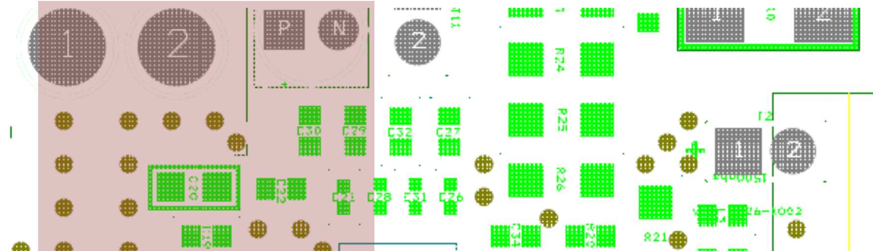

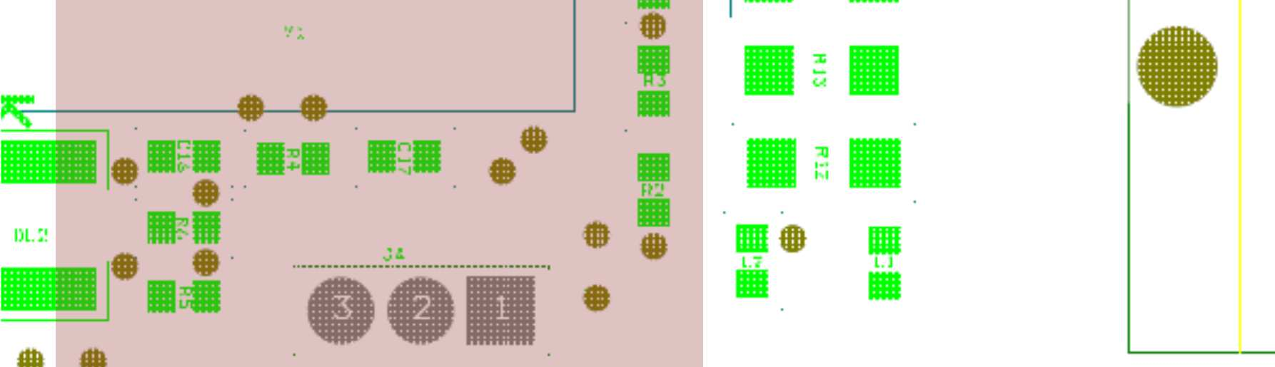


6 Figure 4. Macro-blocks in a STPM3x evaluation PCB Digital Macro-Block Analog Macro-Block September 2014 DT0039 Rev 1 6/12


 get")

7 And below there is the PCB ground planes that lay in the bottom layer: Figure 5. PCB ground planes Digital gnd plane STPM3X Exposed Pad Analog gnd plane The digital ground plane (on the left) get in contact with the analog ground plane just below the STPM3x, by means of its exposed pad. September 2014 DT0039 Rev 1 7/12
8 PCB tips help to improve EFT immunity Due to the environment where energy meters operate, they often face with the problem of electrical fast transient (EFT) bursts. Such kind of disturbances, due to the high-frequency noise and high voltage amplitude can affect the normal operation and sometimes damage the electronic components. Energy meters must withstand EFT bursts without damage, loss of operation and/or loss of measurement accuracy. In order to comply with these restrictions, energy meters are submitted to standard EFT tests, like the IEC test. The characteristics of this test are: Fast repetition of bursts of pulses Max. energy is 4mJ/pulse at 2KV (50ohm impedance) Pulse rise time is 5ns Pulse duration is 50ns (50% amplitude) Here below, the amplitude vs time shape of a single pulse Figure 6. Typical IEC EFT pulse shape The bursts are applied to the power lines with the energy meter connected to the energy utility and the current load. Therefore, the bursts enter the energy meter via the voltage and current sensing circuitry (the voltage divider and the current sensor, especially the shunt sensor which is a non-isolated transducer), but, the high-frequency content of each pulse allows them to couple to other parts of the application through stray capacitance; due to temporary voltage bounces, large differential signals can be generated by inductance of PCB tracks and signal ground. For the digital section of the application, which is September 2014 DT0039 Rev 1 8/12
9 responsible for programming and data transferring, this can lead to an undesirable loss of operation because of data corruption. Like in the previous chapters, the actions that can be put in place against the EFT issue can be split into two separate groups for the analog and the digital blocks of the STPM3x applications: Analog block: the easiest way is to reduce the bandwidth so that the high frequency content of the EFT can be arrested. The required bandwidth for the energy meters is quite low, it often does not exceed the 50th harmonics of the power line frequency (about line), then it can be limited without affecting the measurement performance. The anti-aliasing filters avoid the high-frequencies to reach the analog inputs. Further protection can be added by putting SMD ferrite beads in series to each analog input, but several EFT tests performed on STPM3x show ferrite beads are not necessary. The real improvement comes from an accurate PCB layout design that, basically, should follow the same rules and tips like for accuracy improvement: components very close to the inputs and separate analog ground plane surrounding all the sensitive components. Digital block: since the EFT pulses can corrupt data information and can lead the Digital Signal Processing unit to an inoperative or unpredictable functional state, EFT tetst performed on STPM3x boards show that the communication port terminals must be protected by filtering high-frequency spikes. This has been implemented by adding R-C filters to those terminals. Those filters should be placed close to the STPM3x input pins, rather than the port connectors (UART or SPI headers). Also in this case, the separation of the digital and the analog blocks and the addition of a surrounding ground plane helps to prevent loss of operation, minimizing the crossconduction of high-frequency noise across stray ground loops. September 2014 DT0039 Rev 1 9/12
10 Conclusions The PCB rules described above have been followed during the design of STPM3x demoboards. After the implementation of those rules, accuracy tests and EFT immunity tests show excellent results. Here below a typical accuracy chart: X-axis is the % of the nominal current; Y-axis is the error between measured and supplied energy. Green, Blue and Brown shapes are the limits of the reference standards for 0.5, 1 and 2 accuracy classes: Figure 7. Accuracy chart EFT tests, in accordance with the IEC standard show a correct device operation during and after the EFT injection up to and above 4KV pulse amplitude. Support material Related design support material Product/ system Evaluation board EVALSTPM32; EVALSTPM34; EVALSTPM35 Development kit Gerber files EVALSTPM34_GERBER VAL-STPM34.zip PCB layout, bill of materials and schematics files EVALSTPM33/34_SCHEMATICS ui/static/active/en/resource/technical/layouts_and_diagrams/schematic_pack/33-34%20v2%20schematic.pdf EVALSTPM34_BOM Documentation Datasheet STPM32, STPM33, STPM34 ASSP for metering applications with up to four independent 24-bit, 2nd order, sigma-delta ADCs, 4 MHz OSF and 2 embedded PGLNA September 2014 DT0039 Rev 1 10/12
11 Related design support material User manual, UM1719: The STPM3x evaluation software; UM1748: EVALSTPM34, EVALSTPM33, EVALSTPM32 evaluation board Application note, AN4470: The STPM3x application calibration Revision history Date Version Changes 15-Sep Initial release September 2014 DT0039 Rev 1 11/12
12 IMPORTANT NOTICE PLEASE READ CAREFULLY STMicroelectronics NV and its subsidiaries ( ST ) reserve the right to make changes, corrections, enhancements, modifications, and improvements to ST products and/or to this document at any time without notice. Purchasers should obtain the latest relevant information on ST products before placing orders. ST products are sold pursuant to ST s terms and conditions of sale in place at the time of order acknowledgement. Purchasers are solely responsible for the choice, selection, and use of ST products and ST assumes no liability for application assistance or the design of Purchasers products. No license, express or implied, to any intellectual property right is granted by ST herein. Resale of ST products with provisions different from the information set forth herein shall void any warranty granted by ST for such product. ST and the ST logo are trademarks of ST. All other product or service names are the property of their respective owners. Information in this document supersedes and replaces information previously supplied in any prior versions of this document STMicroelectronics All rights reserved September 2014 DT0039 Rev 1 12/12
AN3353 Application note
 Application note IEC 61000-4-2 standard testing Introduction This Application note is addressed to technical engineers and designers to explain how STMicroelectronics protection devices are tested according
UM1613 User manual. 16-pin smartcard interface ST8034P demonstration board. Introduction
 User manual 16-pin smartcard interface ST8034P demonstration board Introduction The purpose of this document is to describe, and provide information on, how to efficiently use the ST8034P smartcard interface
ETP01-xx21. Protection for Ethernet lines. Features. Description. Applications. Benefits. Complies with the following standards
 ETP0-xx2 Protection for Ethernet lines Features Differential and common mode protection Telcordia GR089 Intrabuilding: 50 A, 2/0 µs ITU-T K20/2: 40 A, 5/30 µs Low capacitance: 3 pf max at 0 V UL94 V0 approved
TS555. Low-power single CMOS timer. Description. Features. The TS555 is a single CMOS timer with very low consumption:
 Low-power single CMOS timer Description Datasheet - production data The TS555 is a single CMOS timer with very low consumption: Features SO8 (plastic micropackage) Pin connections (top view) (I cc(typ)
50 ohm nominal input / conjugate match balun to nrf51822- CEAA/CDAB/CFAC and nrf51422-ceaa/cdab/cfac. Benefits. Description
 50 ohm nominal input / conjugate match balun to nrf51822- /CDAB/CFAC and nrf51422-/cdab/cfac Datasheet production data Benefits Very low profile: < 560 µm after reflow High RF performance RF BOM and area
TDA2003 10W CAR RADIO AUDIO AMPLIFIER
 TDA2003 10W CAR RADIO AUDIO AMPLIFIER DESCRIPTION The TDA 2003 has improved performance with the same pin configuration as the TDA 2002. The additional features of TDA 2002, very low number of external
Application Note, Rev.1.0, September 2008 TLE8366. Application Information. Automotive Power
 Application Note, Rev.1.0, September 2008 TLE8366 Automotive Power Table of Contents 1 Abstract...3 2 Introduction...3 3 Dimensioning the Output and Input Filter...4 3.1 Theory...4 3.2 Output Filter Capacitor(s)
STLQ015. 150 ma, ultra low quiescent current linear voltage regulator. Description. Features. Application
 150 ma, ultra low quiescent current linear voltage regulator Description Datasheet - production data Features SOT23-5L Input voltage from 1.5 to 5.5 V Very low quiescent current: 1.0 µa (typ.) at no load
LM337. Three-terminal adjustable negative voltage regulators. Features. Description
 Three-terminal adjustable negative voltage regulators Datasheet - production data current limit, thermal overload protection and safe area protection. All overload protection circuitry remains fully functional
DSL01-xxxSC5. Secondary protection for DSL lines. Features. Description. Applications. Benefits. Complies with the following standards
 -xxxsc5 Secondary protection for DSL lines Features Low capacitance devices: -xxxsc5: Delta C typ = 3.5 pf High surge capability: 30 A - 8/20 µs Voltage: 8 V, 10.5 V, 16 V, and 24 V RoHS package Benefits
DSL03. Low capacitance TVS for high speed lines such as xdsl. Description. Features. Complies with the following standards
 Low capacitance TVS for high speed lines such as xdsl Description Datasheet - production data Features High surge capability to comply with GR-1089 and ITU-T K20/21 Keeps its peak power capability up to
LM217M, LM317M. Medium current 1.2 to 37 V adjustable voltage regulator. Description. Features
 Medium current 1.2 to 37 V adjustable voltage regulator Datasheet - production data Description The LM217M and LM317M are monolithic integrated circuits in DPAK package used as positive adjustable voltage
TDA2004R. 10 + 10 W stereo amplifier for car radio. Features. Description
 10 + 10 W stereo amplifier for car radio Features Low distortion Low noise Protection against: Output AC short circuit to ground Overrating chip temperature Load dump voltage surge Fortuitous open ground
AND8326/D. PCB Design Guidelines for Dual Power Supply Voltage Translators
 PCB Design Guidelines for Dual Power Supply Voltage Translators Jim Lepkowski ON Semiconductor Introduction The design of the PCB is an important factor in maximizing the performance of a dual power supply
EVAL6491HB. Demonstration board for L6491 gate driver with smartsd. Description. Features
 Demonstration board for L6491 gate driver with smartsd Description Data brief Features High voltage rail up to 600 V dv/dt immunity: 50 V/ns in full temperature range Driver current capability: 4 A source/sink
Description SO-8. Table 1. Device summary. Order codes. SO-8 (tape and reel) TO-92 (Bag) TO-92 (Ammopack) TO-92 (tape and reel)
 TO-92 (Bag) TO-92 (Ammopack) TO-92 (tape and reel)") Low current 1.2 to 37 V adjustable voltage regulators Description Datasheet - production data TO-92 SO-8 TO-92 Tape and reel Bag Ammopack Features Outuput voltage range: 1.2 to 37 V Output current up to
Low current 1.2 to 37 V adjustable voltage regulators Description Datasheet - production data TO-92 SO-8 TO-92 Tape and reel Bag Ammopack Features Outuput voltage range: 1.2 to 37 V Output current up to
Evaluation Board User Guide UG-127
 Evaluation Board User Guide UG-127 One Technology Way P.O. Box 9106 Norwood, MA 02062-9106, U.S.A. Tel: 781.329.4700 Fax: 781.461.3113 www.analog.com Evaluation Board for High Speed Op Amps Offered in
Buffer Op Amp to ADC Circuit Collection
 Application Report SLOA098 March 2002 Buffer Op Amp to ADC Circuit Collection Bruce Carter High Performance Linear Products ABSTRACT This document describes various techniques that interface buffer op
L6234. Three phase motor driver. Features. Description
 Three phase motor driver Features Supply voltage from 7 to 52 V 5 A peak current R DSon 0.3 Ω typ. value at 25 C Cross conduction protection TTL compatible driver Operating frequency up to 150 khz Thermal
STIEC45-xxAS, STIEC45-xxACS
 Transil TVS for IEC 61000-4-5 compliance Datasheet - production data differential mode MIL STD 883G, method 3015-7 Class 3B 25 kv HBM (human body model) Resin meets UL 94, V0 MIL-STD-750, method 2026 solderability
Supply voltage Supervisor TL77xx Series. Author: Eilhard Haseloff
 Supply voltage Supervisor TL77xx Series Author: Eilhard Haseloff Literature Number: SLVAE04 March 1997 i IMPORTANT NOTICE Texas Instruments (TI) reserves the right to make changes to its products or to
LM134-LM234-LM334. Three terminal adjustable current sources. Features. Description
 Three terminal adjustable current sources Features Operates from 1V to 40V 0.02%/V current regulation Programmable from 1µA to 10mA ±3% initial accuracy Description The LM134/LM234/LM334 are 3-terminal
Printed Circuit Boards. Bypassing, Decoupling, Power, Grounding Building Printed Circuit Boards CAD Tools
 Printed Circuit Boards (PCB) Printed Circuit Boards Bypassing, Decoupling, Power, Grounding Building Printed Circuit Boards CAD Tools 1 Bypassing, Decoupling, Power, Grounding 2 Here is the circuit we
AN2604 Application note
 AN2604 Application note STM32F101xx and STM32F103xx RTC calibration Introduction The real-time clock (RTC) precision is a requirement in most embedded applications, but due to external environment temperature
Features. Modulation Frequency (khz) VDD. PLL Clock Synthesizer with Spread Spectrum Circuitry GND
 VDD. PLL Clock Synthesizer with Spread Spectrum Circuitry GND") DATASHEET IDT5P50901/2/3/4 Description The IDT5P50901/2/3/4 is a family of 1.8V low power, spread spectrum clock generators capable of reducing EMI radiation from an input clock. Spread spectrum technique
DATASHEET IDT5P50901/2/3/4 Description The IDT5P50901/2/3/4 is a family of 1.8V low power, spread spectrum clock generators capable of reducing EMI radiation from an input clock. Spread spectrum technique
ICS514 LOCO PLL CLOCK GENERATOR. Description. Features. Block Diagram DATASHEET
 DATASHEET ICS514 Description The ICS514 LOCO TM is the most cost effective way to generate a high-quality, high-frequency clock output from a 14.31818 MHz crystal or clock input. The name LOCO stands for
UA741. General-purpose single operational amplifier. Features. Applications. Description. N DIP8 (plastic package)
") General-purpose single operational amplifier Datasheet - production data N DIP8 (plastic package) D SO8 (plastic micropackage) Pin connections (top view) 1 - Offset null 1 2 - Inverting input 3 - Non-inverting
General-purpose single operational amplifier Datasheet - production data N DIP8 (plastic package) D SO8 (plastic micropackage) Pin connections (top view) 1 - Offset null 1 2 - Inverting input 3 - Non-inverting
A p p l i c a t i o n N o t e
 USB Port Protection The USB-Interface might be the most distributed PC interface in the world. The usage in industryapplications is more and more common. Let s have a closer look to the special environmental
ESDLIN1524BJ. Transil, transient voltage surge suppressor diode for ESD protection. Features. Description SOD323
 Transil, transient voltage surge suppressor diode for ESD protection Datasheet production data Features Max peak pulse power 160 W (8/0 µs) Asymmetrical bidirectional device Stand-off voltage: 15 and 4
AN3306 Application note
 Application note Current sensing in metering applications using a Pulse current sensor and ST metering devices Introduction This application note describes the benefits of a current sensing system for
ICS379. Quad PLL with VCXO Quick Turn Clock. Description. Features. Block Diagram
 Quad PLL with VCXO Quick Turn Clock Description The ICS379 QTClock TM generates up to 9 high quality, high frequency clock outputs including a reference from a low frequency pullable crystal. It is designed
Description. Table 1. Device summary
 2 A positive voltage regulator IC Description Datasheet - production data Features TO-220 Output current up to 2 A Output voltages of 5; 7.5; 9; 10; 12; 15; 18; 24 V Thermal protection Short circuit protection
Application Note AN:005. FPA Printed Circuit Board Layout Guidelines. Introduction Contents. The Importance of Board Layout
 FPA Printed Circuit Board Layout Guidelines By Paul Yeaman Principal Product Line Engineer V I Chip Strategic Accounts Introduction Contents Page Introduction 1 The Importance of 1 Board Layout Low DC
AN2680 Application note
 Application note Fan speed controller based on STDS75 or STLM75 digital temperature sensor and ST72651AR6 MCU Introduction This application note describes the method of defining the system for regulating
Harmonics and Noise in Photovoltaic (PV) Inverter and the Mitigation Strategies
 Inverter and the Mitigation Strategies") Soonwook Hong, Ph. D. Michael Zuercher Martinson Harmonics and Noise in Photovoltaic (PV) Inverter and the Mitigation Strategies 1. Introduction PV inverters use semiconductor devices to transform the
Soonwook Hong, Ph. D. Michael Zuercher Martinson Harmonics and Noise in Photovoltaic (PV) Inverter and the Mitigation Strategies 1. Introduction PV inverters use semiconductor devices to transform the
TESTS OF 1 MHZ SIGNAL SOURCE FOR SPECTRUM ANALYZER CALIBRATION 7/8/08 Sam Wetterlin
 TESTS OF 1 MHZ SIGNAL SOURCE FOR SPECTRUM ANALYZER CALIBRATION 7/8/08 Sam Wetterlin (Updated 7/19/08 to delete sine wave output) I constructed the 1 MHz square wave generator shown in the Appendix. This
AN4646 Application note
 Application note Peripheral interconnections on STM32F401 and STM32F411 lines Introduction On top of the highest performance and the lowest power consumption of the STM32F4 family, STM32F401/411 peripherals
Description. Table 1. Device summary. Order code Package Packing
 4 x 41 W quad bridge car radio amplifier Datasheet - production data Features Flexiwatt25 High output power capability: 4 x 41 W / 4 max. Low distortion Low output noise Standby function Mute function
Application Note AN-1135
 Application Note AN-1135 PCB Layout with IR Class D Audio Gate Drivers By Jun Honda, Connie Huang Table of Contents Page Application Note AN-1135... 1 0. Introduction... 2 0-1. PCB and Class D Audio Performance...
CAN bus ESD protection diode
 Rev. 04 15 February 2008 Product data sheet 1. Product profile 1.1 General description in a small SOT23 (TO-236AB) Surface-Mounted Device (SMD) plastic package designed to protect two automotive Controller
Obsolete Product(s) - Obsolete Product(s)
 - Obsolete Product(s)") 32 W hi-fi audio power amplifier Features High output power (50 W music power IEC 268.3 rules) High operating supply voltage (50 V) Single or split supply operations Very low distortion Short-circuit protection
32 W hi-fi audio power amplifier Features High output power (50 W music power IEC 268.3 rules) High operating supply voltage (50 V) Single or split supply operations Very low distortion Short-circuit protection
LM135-LM235-LM335. Precision temperature sensors. Features. Description
 Precision temperature sensors Features Directly calibrated in K 1 C initial accuracy Operates from 450µA to 5mA Less than 1Ω dynamic impedance TO-92 (Plastic package) Description The LM135, LM235, LM335
Evaluating AC Current Sensor Options for Power Delivery Systems
 Evaluating AC Current Sensor Options for Power Delivery Systems State-of-the-art isolated ac current sensors based on CMOS technology can increase efficiency, performance and reliability compared to legacy
AVX EMI SOLUTIONS Ron Demcko, Fellow of AVX Corporation Chris Mello, Principal Engineer, AVX Corporation Brian Ward, Business Manager, AVX Corporation
 AVX EMI SOLUTIONS Ron Demcko, Fellow of AVX Corporation Chris Mello, Principal Engineer, AVX Corporation Brian Ward, Business Manager, AVX Corporation Abstract EMC compatibility is becoming a key design
Interfacing Intel 8255x Fast Ethernet Controllers without Magnetics. Application Note (AP-438)
") Interfacing Intel 8255x Fast Ethernet Controllers without Magnetics Application Note (AP-438) Revision 1.0 November 2005 Revision History Revision Revision Date Description 1.1 Nov 2005 Initial Release
Interfacing Intel 8255x Fast Ethernet Controllers without Magnetics Application Note (AP-438) Revision 1.0 November 2005 Revision History Revision Revision Date Description 1.1 Nov 2005 Initial Release
STLM20. Ultra-low current 2.4 V precision analog temperature sensor. Features. Applications
 Ultra-low current 2.4 V precision analog temperature sensor Features Precision analog voltage output temperature sensor ±1.5 C maximum temperature accuracy at 25 C (±0.5 C typical) Ultra-low quiescent
Simplifying System Design Using the CS4350 PLL DAC
 Simplifying System Design Using the CS4350 PLL 1. INTRODUCTION Typical Digital to Analog Converters (s) require a high-speed Master Clock to clock their digital filters and modulators, as well as some
32F072BDISCOVERY. Discovery kit for STM32F072xx microcontrollers. Features. Description
 Discovery kit for STM32F072xx microcontrollers Data brief Features STM32F072RBT6 microcontroller featuring 128 KB of Flash memory, 16 KB of SRAM in an LQFP64 package On-board ST-LINK/V2 with switch to
LEVERAGING FPGA AND CPLD DIGITAL LOGIC TO IMPLEMENT ANALOG TO DIGITAL CONVERTERS
 LEVERAGING FPGA AND CPLD DIGITAL LOGIC TO IMPLEMENT ANALOG TO DIGITAL CONVERTERS March 2010 Lattice Semiconductor 5555 Northeast Moore Ct. Hillsboro, Oregon 97124 USA Telephone: (503) 268-8000 www.latticesemi.com
Application Note, V 2.2, Nov. 2008 AP32091 TC1766. Design Guideline for TC1766 Microcontroller Board Layout. Microcontrollers. Never stop thinking.
 Application Note, V 2.2, Nov. 2008 AP32091 TC1766 Design Guideline for TC1766 Microcontroller Board Layout Microcontrollers Never stop thinking. Edition Published by Infineon Technologies AG 81726 München,
AN3252 Application note
 Application note Building a wave generator using STM8L-DISCOVERY Application overview This application note provides a short description of how to use the STM8L-DISCOVERY as a basic wave generator for
STPS5L60. Power Schottky rectifier. Description. Features
 Power Schottky rectifier Datasheet - production data Description Power Schottky rectifier suited for switch mode power supplies and high frequency inverters. This device is intended for use in low voltage
MC33079. Low noise quad operational amplifier. Features. Description
 Low noise quad operational amplifier Datasheet production data Features Low voltage noise: 4.5 nv/ Hz High gain bandwidth product: 15 MHz High slew rate: 7 V/µs Low distortion: 0.002% Large output voltage
Obsolete Product(s) - Obsolete Product(s)
 - Obsolete Product(s)") Vertical deflection booster for 3 App TV/monitor applications with 0 V flyback generator Features Figure. Heptawatt package Power amplifier Flyback generator Stand-by control Output current up to 3.0 App
Vertical deflection booster for 3 App TV/monitor applications with 0 V flyback generator Features Figure. Heptawatt package Power amplifier Flyback generator Stand-by control Output current up to 3.0 App
Features. Description. Table 1. Device summary. Order code Marking Package Packing. STP110N8F6 110N8F6 TO-220 Tube
 N-channel 80 V, 0.0056 Ω typ.,110 A, STripFET F6 Power MOSFET in a TO-220 package Features Datasheet - production data Order code V DS R DS(on)max I D P TOT TAB STP110N8F6 80 V 0.0065 Ω 110 A 200 W TO-220
AN3359 Application note
 Application note Low cost PCB antenna for 2.4GHz radio: Meander design 1 Introduction This application note is dedicated to the STM32W108 product family from STMicroelectronics. One of the main reasons
AN3110 Application note
 Application note Using the STVM100 to automatically adjust VCOM voltage in e-paper Introduction The widespread use of multimedia electronic devices, coupled with environmental concerns over the manufacturing
ICS650-44 SPREAD SPECTRUM CLOCK SYNTHESIZER. Description. Features. Block Diagram DATASHEET
 DATASHEET ICS650-44 Description The ICS650-44 is a spread spectrum clock synthesizer intended for video projector and digital TV applications. It generates three copies of an EMI optimized 50 MHz clock
AN3332 Application note
 Application note Generating PWM signals using STM8S-DISCOVERY Application overview This application user manual provides a short description of how to use the Timer 2 peripheral (TIM2) to generate three
This application note is written for a reader that is familiar with Ethernet hardware design.
 AN18.6 SMSC Ethernet Physical Layer Layout Guidelines 1 Introduction 1.1 Audience 1.2 Overview SMSC Ethernet products are highly-integrated devices designed for 10 or 100 Mbps Ethernet systems. They are
CM1213A-04SO, SZCM1213A-04SO 4-Channel Low Capacitance ESD Protection Array
 CM1213A-04SO, SZCM1213A-04SO 4-Channel Low Capacitance ESD Protection Array Product Description CM1213A 04SO has been designed to provide ESD protection for electronic components or subsystems requiring
Description. Table 1. Device summary. Order codes. TO-220 (single gauge) TO-220 (double gauge) D²PAK (tape and reel) TO-220FP
 TO-220 (double gauge) D²PAK (tape and reel) TO-220FP") 1.2 V to 37 V adjustable voltage regulators Description Datasheet - production data TO-220 TO-220FP The LM217, LM317 are monolithic integrated circuits in TO-220, TO-220FP and D²PAK packages intended for
1.2 V to 37 V adjustable voltage regulators Description Datasheet - production data TO-220 TO-220FP The LM217, LM317 are monolithic integrated circuits in TO-220, TO-220FP and D²PAK packages intended for
TN0023 Technical note
 Technical note Discontinuous flyback transformer description and design parameters Introduction The following is a general description and basic design procedure for a discontinuous flyback transformer.
AND9035/D. BELASIGNA 250 and 300 for Low-Bandwidth Applications APPLICATION NOTE
 BELASIGNA 250 and 300 for Low-Bandwidth Applications APPLICATION NOTE Introduction This application note describes the use of BELASIGNA 250 and BELASIGNA 300 in low bandwidth applications. The intended
AN2866 Application note
 Application note How to design a 13.56 MHz customized tag antenna Introduction RFID (radio-frequency identification) tags extract all of their power from the reader s field. The tags and reader s antennas
VN03. ISO high side smart power solid state relay PENTAWATT. Features. Description. www.tvsat.com.pl
 ISO high side smart power solid state relay Features Type V DSS R DS(on) I n (1) Maximum continuous output current (a) : 4A @ Tc= 25 C 5V logic level compatible input Thermal shutdown Under voltage protection
AN4368 Application note
 Application note Signal conditioning for pyroelectric passive infrared (PIR) sensors Sylvain Colliard-Piraud Introduction Pyroelectric passive infrared (PIR) sensors are widely used in daily life. They
L78MxxAB L78MxxAC. Precision 500 ma regulators. Features. Description
 L78MxxAB L78MxxAC Precision 500 ma regulators Features Output current to 0.5 A Output voltages of 5; 6; 8; 9; 10; 12; 15; 18; 24 V Thermal overload protection Short circuit protection Output transition
AN2760 Application note
 Application note Using clock distribution circuits in smart phone system design Introduction As smart phones become more and more popular in the market, additional features such as A-GPS, Bluetooth, WLAN
QUICK START GUIDE FOR DEMONSTRATION CIRCUIT 956 24-BIT DIFFERENTIAL ADC WITH I2C LTC2485 DESCRIPTION
 LTC2485 DESCRIPTION Demonstration circuit 956 features the LTC2485, a 24-Bit high performance Σ analog-to-digital converter (ADC). The LTC2485 features 2ppm linearity, 0.5µV offset, and 600nV RMS noise.
Application Report. 1 Description of the Problem. Jeff Falin... PMP Portable Power Applications ABSTRACT
 Application Report SLVA255 September 2006 Minimizing Ringing at the Switch Node of a Boost Converter Jeff Falin... PMP Portable Power Applications ABSTRACT This application report explains how to use proper
STCS1A. 1.5 A max constant current LED driver. Features. Applications. Description
 1.5 A max constant current LED driver Features Up to 40 V input voltage Less than 0.5 V voltage overhead Up to 1.5 A output current PWM dimming pin Shutdown pin LED disconnection diagnostic DFN8 (3 x 3
Design and Test of Fast Laser Driver Circuits
 Design and Test of Fast Laser Driver Circuits Since the invention of the laser by Theodore H Maiman 50 years ago, lasers have found widespread applications in various technological fields, such as telecommunications,
STCS1. 1.5 A max constant current LED driver. Features. Applications. Description
 1.5 A max constant current LED driver Features Up to 40 V input voltage Less than 0.5 V voltage overhead Up to 1.5 A output current PWM dimming pin Shutdown pin LED disconnection diagnostic DFN8 (3x3 mm)
AAV003-10E Current Sensor
 Datasheet AAV003-10E Current Sensor Key Features For Low Current Detection On-Chip Current Strap for Precise Operation 80 ma to +80 ma Linear Range Sensitivity up to 2 mv/ma AC or DC Measurement Ultraminiature
Push-Pull FET Driver with Integrated Oscillator and Clock Output
 19-3662; Rev 1; 5/7 Push-Pull FET Driver with Integrated Oscillator General Description The is a +4.5V to +15V push-pull, current-fed topology driver subsystem with an integrated oscillator for use in
STM32F4DISCOVERY. Discovery kit with STM32F407VG MCU. Features. Description
 Discovery kit with STM32F407VG MCU Data brief Features STM32F407VGT6 microcontroller featuring 32-bit ARM Cortex -M4 with FPU core, 1-Mbyte Flash memory, 192-Kbyte RAM in an LQFP100 package On-board ST-LINK/V2
ULN2801A, ULN2802A, ULN2803A, ULN2804A
 ULN2801A, ULN2802A, ULN2803A, ULN2804A Eight Darlington array Datasheet production data Features Eight Darlington transistors with common emitters Output current to 500 ma Output voltage to 50 V Integral
Product Datasheet P1110 915 MHz RF Powerharvester Receiver
 DESCRIPTION The Powercast P1110 Powerharvester receiver is an RF energy harvesting device that converts RF to DC. Housed in a compact SMD package, the P1110 receiver provides RF energy harvesting and power
Miniature Surface-Mount DAA for Audio or Data Transfer XE0402LCC BLOCK DIAGRAM
 XE0402LCC January 2007 Miniature Surface-Mount DAA for Audio or Data Transfer Description The XE0402LCC supplies a complete telephone line interface or DAA (Data Access Arrangement) in a miniature, surface-mount
Table 1. Absolute maximum ratings (T amb = 25 C) Symbol Parameter Value Unit. ISO 10605 - C = 330 pf, R = 330 Ω : Contact discharge Air discharge
 Symbol Parameter Value Unit. ISO 10605 - C = 330 pf, R = 330 Ω : Contact discharge Air discharge") Automotive dual-line Transil, transient voltage suppressor (TVS) for CAN bus Datasheet - production data Complies with the following standards ISO 10605 - C = 150 pf, R = 330 Ω : 30 kv (air discharge)
Automotive dual-line Transil, transient voltage suppressor (TVS) for CAN bus Datasheet - production data Complies with the following standards ISO 10605 - C = 150 pf, R = 330 Ω : 30 kv (air discharge)
CS4525 Power Calculator
 1. OVERVIEW CS4525 Power Calculator The CS4525 Power Calculator provides many important application-specific performance numbers for the CS4525 based on user-supplied design parameters. The Power Calculator
AVR127: Understanding ADC Parameters. Introduction. Features. Atmel 8-bit and 32-bit Microcontrollers APPLICATION NOTE
 Atmel 8-bit and 32-bit Microcontrollers AVR127: Understanding ADC Parameters APPLICATION NOTE Introduction This application note explains the basic concepts of analog-to-digital converter (ADC) and the
PS25202 EPIC Ultra High Impedance ECG Sensor Advance Information
 EPIC Ultra High Impedance ECG Sensor Advance Information Data Sheet 291498 issue 2 FEATURES Ultra high input resistance, typically 20GΩ. Dry-contact capacitive coupling. Input capacitance as low as 15pF.
BD241A BD241C. NPN power transistors. Features. Applications. Description. NPN transistors. Audio, general purpose switching and amplifier transistors
 BD241A BD241C NPN power transistors Features. NPN transistors Applications Audio, general purpose switching and amplifier transistors Description The devices are manufactured in Planar technology with
August 2001 PMP Low Power SLVU051
 User s Guide August 2001 PMP Low Power SLVU051 IMPORTANT NOTICE Texas Instruments and its subsidiaries (TI) reserve the right to make changes to their products or to discontinue any product or service
PRTR5V0U2F; PRTR5V0U2K
 Rev. 02 19 February 2009 Product data sheet 1. Product profile 1.1 General description Ultra low capacitance double rail-to-rail ElectroStatic Discharge (ESD) protection devices in leadless ultra small
Single LNB supply and control IC DiSEqC 1.X compliant with EXTM based on the LNBH29 in a QFN16 (4x4) Description
 Description") Single LNB supply and control IC DiSEqC 1.X compliant with EXTM based on the LNBH29 in a QFN16 (4x4) Data brief Low-drop post regulator and high-efficiency step-up PWM with integrated power N-MOS allowing
Single LNB supply and control IC DiSEqC 1.X compliant with EXTM based on the LNBH29 in a QFN16 (4x4) Data brief Low-drop post regulator and high-efficiency step-up PWM with integrated power N-MOS allowing
PL-277x Series SuperSpeed USB 3.0 SATA Bridge Controllers PCB Layout Guide
 Application Note PL-277x Series SuperSpeed USB 3.0 SATA Bridge Controllers PCB Layout Guide Introduction This document explains how to design a PCB with Prolific PL-277x SuperSpeed USB 3.0 SATA Bridge
LEDs offer a more energy efficient and no radiated heat, no Ultra Violet light solution to replace some halogen lamp applications.
 A Product Line of Diodes Incorporated DN96 MR11 LED Lighting application with AL8805 Introduction MR11 lamps are one variety of Multifaceted Reflector (MR) lamps that usually employ a halogen filament
Balun Parameter Definitions & Measurement May 2004
 Balun Parameter Definitions & Measurement May 2004 Differential circuits are becoming more widely used in RF circuits for the same reason that they have been used for years in lower frequency circuits.
Output Ripple and Noise Measurement Methods for Ericsson Power Modules
 Output Ripple and Noise Measurement Methods for Ericsson Power Modules Design Note 022 Ericsson Power Modules Ripple and Noise Abstract There is no industry-wide standard for measuring output ripple and
CAPACITIVE SENSING MADE EASY, Part 2 Design Guidelines
 CAPACITIVE SENSING MADE EASY, Part 2 Design Guidelines By Pushek Madaan and Priyadeep Kaur, Cypress Semiconductor Corp. When it comes to capacitive sensing design, layout plays a crucial role. Giving importance
AN2389 Application note
 Application note An MCU-based low cost non-inverting buck-boost converter for battery chargers Introduction As the demand for rechargeable batteries increases, so does the demand for battery chargers.
Digital to Analog Converter. Raghu Tumati
 Digital to Analog Converter Raghu Tumati May 11, 2006 Contents 1) Introduction............................... 3 2) DAC types................................... 4 3) DAC Presented.............................
How to design SMPS to Pass Common Mode Lightning Surge Test
 Application Note, V1.0, September 2006 How to design SMPS to Pass Common Mode Lightning Surge Test Power Management & Supply N e v e r s t o p t h i n k i n g. Edition 2006-09-06 Published by Infineon
Description. Table 1. Device summary. Order code Temperature range Package Packaging Marking
 14-stage ripple carry binary counter/divider and oscillator Applications Automotive Industrial Computer Consumer Description Datasheet - production data Features Medium speed operation Common reset Fully
AN4571 Application note
 Application note STM32 BLE toolbox for Android Introduction The application note describes the STM32 Bluetooth low energy (BLE) toolbox Android application (STSW-STM32153) to be used with an Android 4.3
Cumbria Designs T-1. SSB/CW Filter kit (4.9152MHz) User Manual
 User Manual") Cumbria Designs T-1 SSB/CW Filter kit (4.9152MHz) User Manual CONTENTS 1 INTRODUCTION 2 2 CIRCUIT DESCRIPTION 2 3 ASSEMBLY 2 4 TESTING 4 The Steading Stainton PENRITH Cumbria CA11 0ES UK 1 Introduction
Cumbria Designs T-1 SSB/CW Filter kit (4.9152MHz) User Manual CONTENTS 1 INTRODUCTION 2 2 CIRCUIT DESCRIPTION 2 3 ASSEMBLY 2 4 TESTING 4 The Steading Stainton PENRITH Cumbria CA11 0ES UK 1 Introduction
ICS650-01 SYSTEM PERIPHERAL CLOCK SOURCE. Description. Features. Block Diagram DATASHEET
 DATASHEET ICS650-01 Description The ICS650-01 is a low-cost, low-jitter, high-performance clock synthesizer for system peripheral applications. Using analog/digital Phase-Locked Loop (PLL) techniques,