Specifications, Installation, and Operating Instructions
|
|
|
- Ruby Conley
- 7 years ago
- Views:
Transcription


1 Specifications, Installation, and Operating Instructions Model: SP Plus Family CAUTION: THE INSTALLATION OF A SURGE PROTECTION DEVICE () MUST BE DONE BY QUALIFIED ELECTRICAL PERSONNEL. A MUST BE GROUNDED THROUGH THE POWER SYSTEM GROUND FOR PROPER OPERATION. WARNING: BEFORE INSTALLING THE SUPPRESSOR, AC POWER MUST BE OFF. FAILURE TO DO SO COULD RESULT IN DAMAGE TO THE SUPPRESSOR AND POSES A POTENTIAL ELECTRICAL SHOCK HAZARD TO PERSONNEL. WARNING: READ LABEL ON SIDE OF THE ENCLOSURE TO VERIFY VOLTAGE CONFIGURATION. WARNING: DISCONTINUE INSTALLATION IF THE MEASURED VOLTAGE IS NOT IN THE RANGE OF THE MODEL VOLTAGE CONFIGURATION OF THE BEING INSTALLED. CONTACT LEA INTERNATIONAL S TECHNICAL SUPPORT WITH ANY QUESTIONS CONCERNING THE VOLTAGE CONFIGURATION PRIOR TO INSTALLATION AND APPLICATION OF POWER. B Rev D 1
2 Contents: TITLE PAGE Specifications 3 Pre-Installation Notes 4 Installation Procedure 4 Installation Checklist 4 Troubleshooting 5 Wiring Diagrams 5 Part Number Model: Type II Description B SP /240-SP MOV 100kA, NEMA 4X plastic encl, Single Phase, Alarm/no Switch 2 B SP /240-SP MOV 100kA, NEMA 1 plastic encl, Single Phase, Alarm/with Switch 2 B SP /208-3Y MOV 100kA, NEMA 4X plastic encl, Wye, Alarm/no Switch 3 B SP /208-3Y MOV 100kA, NEMA 1 plastic encl, Wye, Alarm/with Switch 3 Fig. Ref. B SP /480-3Y MOV 100kA, NEMA 4X plastic encl, Wye, Alarm/no Switch (Option) MOV 100kA, NEMA 1 plastic encl, Wye, Alarm/with Switch 3 B SP /240-SP MOV 200kA, NEMA 4X plastic encl, Single Phase, Alarm/no Switch (Option) MOV 200kA, NEMA 1 plastic encl, Split Phase, Alarm/with Switch 5 B SP /208-3Y MOV 200kA, NEMA 4X plastic encl, Wye, Alarm/no Switch (Option) MOV 200kA, NEMA 1 plastic encl, Wye, Alarm/with Switch 6 B SP /480-3Y MOV 200kA, NEMA 4X plastic encl, Wye, Alarm/no Switch (Option) MOV 200kA, NEMA 1 plastic encl, Wye, Alarm/with Switch 6 B SP D MOV 200kA, NEMA 4X plastic encl, Delta, Alarm/no Switch 7 Model: Type I B SP /240-1 MOV 100kA, NEMA 4X plastic encl, Single Phase, Alarm/no Switch 2 B SP /240-1 MOV 100kA, NEMA 1 plastic encl, Single Phase, Alarm/with Switch 2 B Rev D 2
3 Specifications: All Models Protection Provided,,, (Single Phase, Wye);, (Delta) Maximum Surge Current 100,000 Amps SP-100 Dissipation per Phase* 200,000 Amps SP-200 Nominal Discharge Current (In) Maximum Load Current per Phase 20 ka Unlimited Operating Temperature Range -40 C to +85 C Operating Humidity (noncondensing) 5% to 95% Operating Altitude (feet) Up to 12,000 Certifications UL rd Edition Listed (E315238) *8 x 20 µsec I wave per ANSI/IEEE C62.41 Model SP /240 SP /208 SP /480 SP /240 SP /208 SP /480 SP /240-1 SP Product Type Type 1 V (V ac) Phase VPR (Vpk) In MCOV 120/ /208 3Y 277/480 3Y 120/ /208 3Y 277/480 3Y 120/ D ka 127/ ka 127/ ka 293/ ka 127/ ka 127/ ka 293/ ka 138/ ka 508 B Rev D 3
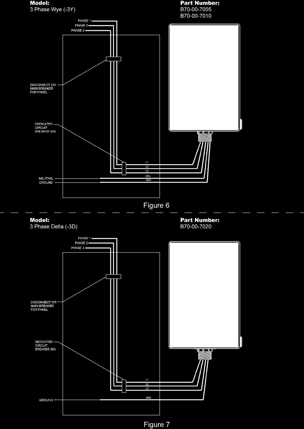
4 PRE-INSTALLATION NOTES Please read the entire installation manual before installing this. Unpack unit carefully, removing packing material. Inspect for damages during shipment. If unit seems damaged, contact LEA International and shipping agency. Do not continue to install unit. Confirm install location temperature will not exceed rating (-40 C to +85 C). Verify that all nuts and bolts have good tight connections. Verify install location meets enclosure NEMA type rating (1 or 4) per label. Electrical Specification for Installation: Verify the voltage configuration of the matches actual system voltage configuration of service point. Ground resistance is less than 25 ohms and all wiring conductors are in accordance with the appropriate layout/installation drawing. INSTALLATION PROCEDURE Length of leads and conductor size: Leads must be as short as possible, not exceeding the recommended length of a foot and a half (1.5 ); and routed with gradual bends avoiding sharp or 90 bends. The comes with #10 AWG wire pre-cut for installation. Extending existing wire by splicing is not recommended. Mounting: The is installed in parallel with the incoming phase conductors. After removing the clear enclosure cover screws mount the using the concealed screw holes located near each outside corner of the enclosure. For the SP100, the mounting holes of the enclosure have a distance in length (from top to bottom) of and a distance in width (from left to right) of And for the SP200, the mounting holes of the enclosure have a distance in length (from top to bottom) of 9.00 and a distance in width (from left to right) of 5.10.The should be mounted as close as possible to the connection of service point; utilizing a ½ knockout in the panel. Secure a conduit locknut onto the ½ nipple before proceeding. Electrical Connection: Connect the phase input wires (black) to the terminals marked phase 1, phase 2, or phase 3 inputs as illustrated on the drawings. Connect the neutral input wires (white) to the terminal marked neutral in the service point, as illustrated in drawings (if applicable). Connect the ground leads (green) to the terminal marked ground in the service point, as illustrated in the drawings. It is recommended to use a minimum 30 Amp circuit breaker when connecting the. Final check: Check installation of unit as indicated in installation drawings. Apply external AC power to the. The unit is operational. If all green indicator lamps are illuminated. If not, contact LEA International s technical support at Visual inspection: Operational status of the is verified by observing the phase status indicator LED(s). The LED, illuminated Green indicates normal operation with all protection modes functioning. INSTALLATION CHECKLIST: YES NO [ ] [ ] The voltage configuration of the matches actual voltage configuration of service point. [ ] [ ] Ground resistance is less than 25 ohms. [ ] [ ] All wiring conforms to the national electric code (NEC) [ ] [ ] All conductors are in accordance with the appropriate layout/installation drawing. [ ] [ ] All lead lengths are as short as possible. [ ] [ ] The is installed in parallel with the incoming phase conductors. [ ] [ ] After installation, all lights are illuminated green. [ ] [ ] All critical loads are protected by the. If not, additional (s) may be required. B Rev D 4
5 TROUBLESHOOTING Problem Alarm sound is audible Status LED(s) are red Status LED(s) are not illuminated Solution If disable switch is available. Silence alarm by using disable switch; otherwise use the circuit breaker to disconnect power and silence the alarm. This indicates loss of protection in phase(s), unit may need replacement. Please call LEA technical support to check warranty. This indicates a loss of power. Please verify power is being supplied to service point; if problem persist, call LEA technical support. LEA Technical Support is available at Wiring Diagrams: The following section contains all layout/installation drawings found within the SP Plus Family. Locate the appropriate drawing based on the model number of your system. B Rev D 5

6 B Rev D 6
7 B Rev D 7

8 B Rev D 8
TSn SERIES Surge Protective Device
 Page: 1 of 8 TSn SERIES Surge Protective Installation & Operation Manual 3621 Saunders Avenue www.systems.us Ph 804.355.1100 Richmond, VA 23227 4354 Sales@Systems.us Fax 804.355.8900 Page: 2 of 8 Quick
INSTALLATION INSTRUCTIONS
 LIGHTING CONTROL PANELS 4 AND 8 RELAYS INSTALLATION INSTRUCTIONS INSTALLATION OVERVIEW The installation instructions contained in this document are provided as a guide for proper and reliable installation.
SURGE PROTECTIVE DEVICES (SPDs) LOW VOLTAGE AC INTEGRATED SURGE PROTECTION FOR ELECTRICAL DISTRIBUTION SYSTEMS SECTION 16671A SECTION 16671A
 LOW VOLTAGE AC INTEGRATED SURGE PROTECTION FOR ELECTRICAL DISTRIBUTION SYSTEMS SECTION 16671A SECTION 16671A") SURGE PROTECTIVE DEVICES (SPDs) INTEGRATED UNITS LOW VOLTAGE AC SURGE PROTECTION FOR ELECTRICAL DISTRIBUTION SYSTEMS PART 1 GENERAL 01 02 03 SCOPE The Contractor shall furnish and install the Surge Protective
SURGE PROTECTIVE DEVICES (SPDs) INTEGRATED UNITS LOW VOLTAGE AC SURGE PROTECTION FOR ELECTRICAL DISTRIBUTION SYSTEMS PART 1 GENERAL 01 02 03 SCOPE The Contractor shall furnish and install the Surge Protective
Project Name: Nortrax Section 26 41 00 Project No: 13-013 SURGE PROTECTION DEVICES Page 1
 Page 1 PART 1 - GENERAL 1.1 RELATED DOCUMENTS A. General: Drawings and general provisions of the Contract, including General and Supplementary Conditions and Divisions 1 Specification sections apply to
ETC TWO STAGE ELECTRONIC TEMPERATURE CONTROL
 RANCO INSTALLATION INSTRUCTIONS ETC TWO STAGE ELECTRONIC TEMPERATURE CONTROL Relay Electrical Ratings PRODUCT DESCRIPTION The Ranco ETC is a microprocessor-based family of electronic temperature controls,
Parallel Redundant Uninterruptible Power Supply
 9 315 Parallel Redundant Uninterruptible Power Supply Installation/Operation Manual 164202013 Rev. D ------------------------------------------------------------------------ ------------------------------------------------------------------------
ATS Overhead Table Shelf System INSTRUCTION MANUAL
 ATS Overhead Table Shelf System INSTRUCTION MANUAL ATS Overhead Table Shelf System Instruction Manual Warranty Newport Corporation warrants this product to be free of defects in material and workmanship
IntelliBrite Controller (For IntelliBrite Pool, Spa and Landscape Lighting Fixtures) Installation and User s Guide
 Installation and User s Guide") IntelliBrite Controller (For IntelliBrite Pool, Spa and Landscape Lighting Fixtures) Installation and User s Guide *619751* P/N 619751 - Rev C IMPORTANT SAFETY INSTRUCTIONS READ AND FOLLOW ALL INSTRUCTIONS
IntelliBrite Controller (For IntelliBrite Pool, Spa and Landscape Lighting Fixtures) Installation and User s Guide *619751* P/N 619751 - Rev C IMPORTANT SAFETY INSTRUCTIONS READ AND FOLLOW ALL INSTRUCTIONS
READ THIS MANUAL BEFORE PROCEEDING WITH THE INSTALLATION. FAILURE TO FOLLOW THE INSTALLATION INSTRUCTIONS MAY VOID YOUR WARRANTY!
 READ THIS MANUAL BEFORE PROCEEDING WITH THE INSTALLATION. FAILURE TO FOLLOW THE INSTALLATION INSTRUCTIONS MAY VOID YOUR WARRANTY! The main power to any existing system must be disconnected prior to the
OASIS-PLUS 120V READ ALL INSTRUCTIONS BEFORE OPERATING READ ALL INSTRUCTIONS BEFORE OPERATING OZONE IS A POWERFUL OXIDIZER AND MUST BE USED WITH CARE
 OASIS-PLUS 120V INFORMATION & OPERATING INSTRUCTIONS READ ALL INSTRUCTIONS BEFORE OPERATING READ ALL INSTRUCTIONS BEFORE OPERATING OZONE IS A POWERFUL OXIDIZER AND MUST BE USED WITH CARE 56041852 WARNING:
Owner s Manual. For Automatic Transfer Switch. 100-200 Amp, Service Entrance/Non-Service Entrance
 Owner s Manual For Automatic Transfer Switch 100-200 Amp, Service Entrance/Non-Service Entrance Model Numbers RTST100A3 RTSP100A3 RTST150A3 RTST200A3 RTSP200A3 MODEL NUMBER: SERIAL NUMBER: DATE PURCHASED:
Freeze Protection Thermostats MODELS SST 2. Installation and Operation Manual
 Freeze Protection Thermostats MODELS SST 2 Part Number 22744 MANUAL We Manage Heat Installation and Operation Manual Environmental Technology, Inc. 1850 N Sheridan Street South Bend, Indiana 46628 (574)
Contractors Guide Central Inverter System Installation
 Contractors Guide Central Inverter System Installation Step By Step Procedures 2,200 Watt/VA 6 Step Installation 1. Mount Bottom Cabinet 2. Mount Top Cabinet 3. Install Batteries 4. Install Conduit 5.
ISL-540 TBTS SERIES D EMERGENCY LIGHTING EQUIPMENT
 P.O. BOX 11846 TUCSON, AZ 85734 (520) 294-3292 FAX (520) 741-2837 www.iotaengineering.com INSTRUCTION MANUAL IMPORTANT SAFEGUARDS When using electrical equipment, basic safety precautions should always
AMERBRITE UNDERWATER WHITE LED POOL LAMP
 AMERBRITE UNDERWATER WHITE LED POOL LAMP FOR USE ONLY WITH PENTAIR AMERLITE LUMINAIRE INSTALLATION AND USER S GUIDE IMPORTANT SAFETY INSTRUCTIONS READ AND FOLLOW ALL INSTRUCTIONS SAVE THESE INSTRUCTIONS
PART 8: FIELD WIRING. n WARNING NOTICE. Boiler Manual
 PART 8: FIELD WIRING A. INSTALLATION MUST COMPLY WITH: 1. National Electrical Code and any other national, state, provincial or local codes or regulations. 2. In Canada, CSA C22.1 Canadian Electrical Code
Installation. Smart-UPS VT MGE Galaxy 3500. Maintenance Bypass Panel. 10-40 kva 400 V
 Installation Smart-UPS VT MGE Galaxy 3500 Maintenance Bypass Panel 10-40 kva 400 V Contents Safety.................................................. 1 Save these instructions...................................
Wiser Panel Meter, Model Number WISERCTPM200 Installer s Guide
 Instruction Bulletin EAV85226 08/2014 Wiser Panel Meter, Model Number WISERCTPM200 Installer s Guide Retain for future use. Product Description Kit Contents The Wiser Panel Meter is for use in energy management
TC-9102 Series Surface Mount Temperature Controllers
 TC-9102 Series Surface Mount Temperature Controllers General Description & Applications The TC-9102 Series Temperature Controller offers a versatile solution for a wide variety of applications that may
EKOS Cart. Instructions for Use
 EKOS Cart Instructions for Use EKOS Corporation 11911 North Creek Parkway South Bothell, WA 98011 USA (425) 415-3100 (tel) (425) 415-3102 (fax) info@ekoscorp.com (e-mail) - 1-4913-002 REV E Intended Use
SURGE PROTECTIVE DEVICES
 SURGE PROTECTIVE DEVICES 1. INTRODUCTION In order to ensure safety of people, protection of equipment and, to a certain extent, continuity of supply, insulation co-ordination aims at reducing the likelihood
White Paper SolarEdge Three Phase Inverter System Design and the National Electrical Code. June 2015 Revision 1.5
 White Paper SolarEdge Three Phase Inverter System Design and the National Electrical Code June 2015 Revision 1.5 Shalhevet Bar-Asher; SolarEdge Technologies, Inc. Bill Brooks, PE; Brooks Engineering LLC
MTE SERIES RLW. World REACTORS USER MANUAL PART NO. INSTR 030 REL. 090930. 2009 MTE Corporation
 MTE SERIES RLW World REACTORS USER MANUAL PART NO. INSTR 030 REL. 090930 2009 MTE Corporation IMPORTANT USER INFORMATION NOTICE MTE Series RLW reactors are components designed to improve the reliability
Solid Core and Split Core Adjustable Current Status Switches CSS-O, CSS-C; CSP-O, CSP-C
 Solid Core and Split Core Adjustable Current Status Switches CSS-O, CSS-C; CSP-O, CSP-C DESCRIPTION FEATURES PRODUCT DATA Very low operating trip points LED status indication Integral DIN rail mounting
12 Volt 30 Amp Digital Solar Charge Controller
 12 Volt 30 Amp Digital Solar Charge Controller User s Manual WARNING Read carefully and understand all INSTRUCTIONS before operating. Failure to follow the safety rules and other basic safety precautions
SURGE PROTECTIVE DEVICES (SPDs) LOW VOLTAGE AC EXTERNAL SIDEMOUNT SURGE PROTECTION FOR ELECTRICAL DISTRIBUTION SYSTEMS SECTION 16671B SECTION 16671B
 LOW VOLTAGE AC EXTERNAL SIDEMOUNT SURGE PROTECTION FOR ELECTRICAL DISTRIBUTION SYSTEMS SECTION 16671B SECTION 16671B") SURGE PROTECTIVE DEVICES (SPDs) EXTERNAL SIDEMOUNT UNITS LOW VOLTAGE AC SURGE PROTECTION FOR ELECTRICAL DISTRIBUTION PART 1 GENERAL 01 02 03 SCOPE The Contractor shall furnish and install the Surge Protective
SURGE PROTECTIVE DEVICES (SPDs) EXTERNAL SIDEMOUNT UNITS LOW VOLTAGE AC SURGE PROTECTION FOR ELECTRICAL DISTRIBUTION PART 1 GENERAL 01 02 03 SCOPE The Contractor shall furnish and install the Surge Protective
Tips for connecting 24-volt power
 Digital Designer s Guide Application NoteAN0604D Revision B Tips for connecting 24-volt power This application note covers choosing a transformer and connecting 24 volt AC power to a KMC Controls DDC controller.
I nstallation. M100Q Series Proportional Actuator with R81Q Controller Board for Thermistor Sensor Applications. Tools Needed.
 FANs 268.1, 1628.3 Installation Bulletin M100Q Issue Date 1099 M100Q Series Proportional Actuator with R81Q Controller Board for Thermistor Sensor Applications I nstallation Parts Included M110QGA-1 and
METER REQUIREMENTS GENERAL REQUIREMENTS SECTION D
 12 - ELECTRIC SERVICE HANDBOOK SECTION D METER REQUIREMENTS This chapter gives you information on Central Lincoln s metering requirements. It's divided into three sections: General requirements This section
INSTALLATION GUIDE LOW VOLTAGE TRANSFORMER
 INSTALLATION GUIDE LOW VOLTAGE TRANSFORMER 300W 600W 900W 1200W ATTENTION: Please read and understand thoroughly this installation guide to ensure safe and efficient operation of this Power Module 1 Open
SECTION 26 09 13 - POWER MONITOR FOR ELECTRICAL, STEAM CONDENSATE, AND WATER PART I - GENERAL
 SECTION 26 09 13 - POWER MONITOR FOR ELECTRICAL, STEAM CONDENSATE, AND WATER PART I - GENERAL 1.1 SUMMARY A. This section describes the requirements for the installation of Power Monitors and associated
PS4-24 OWNERS MANUAL 24 VAC 90 WATT WALL MOUNTED CCTV POWER SUPPLY
 PS4-24 OWNERS MANUAL 24 VAC 90 WATT WALL MOUNTED CCTV POWER SUPPLY 7320 Ashcroft, Suite 104 Houston, Texas 77081 p: 713-772-1404 f: 713-772-7360 e: info@juicegoose.com www.juicegoose.com 06-06 CONGRATULATIONS
WARNING: FAILURE TO FOLLOW THESE RULES MAY RESULT IN SERIOUS PERSONAL INJURY CAUTION: INSTALLATION LOCATION:
 Revision Level: 01 Revision Date: 07/07/2011 Please read all instructions carefully to help ensure a correct and SAFE installation of your Second Wind Ultraviolet Germicidal Air Purifier. Failure to do
PT-6000 Power Tower INSTALLATION MANUAL SPECIFICATIONS
 PT-6000 Power Tower INSTALLATION MANUAL 10.5 9.75 12 22.75 10.75 MAXIMUM SOIL HEIGHT: DO NOT ALLOW FILL TO EXCEED THIS LEVEL! 11.5 4 4 13 Optional PT-BASE for new installations or when previous 2000/6000
Power surges can also be generated by equipment in your facility such as:
 Power Quality Surge Suppressors What is Surge Protection A surge suppressor can be the first and best defense against the instant or gradual destruction of electrical equipment. Compared to the replacement
CalMod Design-Build Electrification Services
 SECTION 28 16 00 INTRUSION DETECTION SYSTEM PART 1 - GENERAL 1.1 DESCRIPTION A. This section describes the detailed technical requirements for the Intrusion Detection System (IDS), where the Contractor
Advantium 2 Plus Alarm
 ADI 9510-B Advantium 2 Plus Alarm INSTALLATION AND OPERATING INSTRUCTIONS Carefully Read These Instructions Before Operating Carefully Read These Controls Corporation of America 1501 Harpers Road Virginia
LIEBERT VNSA Installation Sheet
 LIEBERT VNSA Installation Sheet Description The Liebert vnsa network switch is designed for connecting multiple Ethernet-ready devices and comes in various models. The unit may have: A Liebert icom display
Intersection Preassembled 19-inch Rack
 Intersection Preassembled 19-inch Rack The intersection preassembled 19-inch rack comes fully assembled, wired and ready to be installed in a server rack. The rack provides communications, power conversion
T7079A,B Solid State Remote Temperature Controllers
 T7079A,B Solid State Remote Temperature Controllers FEATURES PRODUCT DATA Switch selection of heat or cool mode. Temperature sensing up to 400 feet. Does not require field calibration. 0K NTC temperature
Troubleshooting Guide, Freedom and Fleet Power Inverter/Chargers
 Technical Note Freedom/Fleet Power 512-0084-01-01 Rev 1 Troubleshooting Guide, Freedom and Fleet Power Inverter/Chargers Overview This document is a guide for troubleshooting inverters, battery chargers,
DIGITAL ALARM II FOR HOSPITALS AND LABORATORIES INSTALLATION AND OPERATING INSTRUCTIONS 52 635.0
 Form No. 74-00-4001 S168-195-001 Revision E DIGITAL ALARM II FOR HOSPITALS AND LABORATORIES INSTALLATION AND OPERATING INSTRUCTIONS 52 635.0 INTRODUCTION Allied Healthcare Products, Inc. s Digital Alarm
ELECTRICAL GUIDELINES FOR SINGLE-FAMILY HOME OWNERS:
 ELECTRICAL GUIDELINES FOR SINGLE-FAMILY HOME OWNERS: Chapter 12 of the Burlington Code of ordinances allows owner occupants of single family homes to do their own wiring if they choose. If you choose to
Owner's/Installation Manual
 Owner's/Installation Manual Power Management Module (PMM) and Starter Kit NOTE: The starter kit must be purchased and installed prior to individual PMM usage. Model Numbers: 00686-0 PMM 00699-0 PMM WITH
2a. IEM Indoor Metal Clad Medium Voltage Switchgear 15KV 16346-1. 2a. Section 16346 INDOOR METAL CLAD MEDIUM VOLTAGE SWTICHGEAR (Std.
 2a. IEM Indoor Metal Clad Medium Voltage Switchgear 15KV 16346-1 2a. Section 16346 INDOOR METAL CLAD MEDIUM VOLTAGE SWTICHGEAR (Std. Relays) Part 1 General 1.1 CONDITIONS AND REQUIREMENTS: A. Refer to
Introduction. Safety Guidelines. Part Numbers. Operation and Maintenance Manual. Operation and Maintenance Manual
 Operation and Maintenance Manual Introduction Read all instructions thoroughly. Installation of the OilTector must comply with all Federal, State and Local Codes, Regulations and Practices. The OilTector
Power Supply and Indicator Unit Type 5024-1. Fig. 1 Type 5024-1. Mounting and Operating Instructions EB 9539 EN
 Power Supply and Indicator Unit Type 5024-1 Fig. 1 Type 5024-1 Mounting and Operating Instructions EB 9539 EN Edition October 2003 Application 1 Application The Type 5024-1 Power Supply and Indicator Unit
HP UPS R1500 Generation 3
 HP UPS R1500 Generation 3 Installation Instructions Part Number 650952-001 NOTE: The rating label on the device provides the class (A or B) of the equipment. Class B devices have a Federal Communications
AMFA-27 AMFA-29. Operator s Manual & Installation Instructions. Rev. 2.5
 AMFA-27 AMFA-29 Operator s Manual & Installation Instructions Rev. 2.5 Date: 17 July, 2010 Permanently-connected, utility Interactive, single-phase, inverters Model AMFA-27 WIND TURBINE INVERTER (240 VAC
DIVISION 28 ELECTRONIC SAFETY AND SECURITY SECTION 28 13 00 SECURITY AND ACCESS CONTROL SYSTEM
 DIVISION 28 ELECTRONIC SAFETY AND SECURITY PART 1 GENERAL 1.01 DESCRIPTION A. Division 28 Contractor shall extend a complete Matrix Systems Access Control System as shown on the Drawings and as specified
Instructions & Safety Information Models A220-20D and A220-20L Version 2
 Quick 220 Voltage Converting Power Supply Instructions & Safety Information Models A220-20D and A220-20L Version 2 Quick 220 Systems LLC PO Box 47489 Phoenix, Arizona 85068-7489 800-347-0394 602-938-6057
Air-cooled Generator Battery Charger Installation Guidelines
 Air-cooled Generator Battery Charger Installation Guidelines Table of Contents Table of Contents...Inside Front Cover Section 1 General Information... IFC 1.1 Introduction...IFC 1.2 Battery Charger Compatibility...
Roof Top Air Conditioner INSTALLATION AND OPERATING INSTRUCTIONS
 Roof Top Air Conditioner INSTALLATION AND OPERATING INSTRUCTIONS Ducted System RECORD THIS UNIT INFORMATION FOR FUTURE REFERENCE: Model Number: Serial Number: Date Purchased: This manual must be read and
OPL BASIC. Dosing System for Professional Laundry machines. Contents
 OPL BASIC Dosing System for Professional Laundry machines Contents 1 Getting Started. Page 2 2 Installation. Page 4 3 Set Up & Operation. Page 8 4 Maintenance & Accessories. Page 10 5 Troubleshooting Page
EMBEDDED ACCESS CONTROL Hardware Installation Guide
 EMBEDDED ACCESS CONTROL Hardware Installation Guide Lenel goentry Hardware Installation Guide, product version 1.00. This guide is item number DOC- ENHW-ENU, revision 1.003, April 2009 Copyright 2009 Lenel
Fire Fighter Phone System Installation Instructions
 Fire Fighter Phone System Installation Instructions Introduction This publication describes the installation procedure for the Fire Fighter s Phone on a 4100U or a 4100ES Fire Alarm Control Panel (FACP).
42U/45U 28" Wide Rack Installation & Service Guide
 42U/45U 28" Wide Rack Installation & Service Guide 96-00171-005 Rev B Important Information Information in this document is subject to change without notice and does not represent a commitment on the part
HP R12000 and R18000 DirectFlow UPS User Guide
 HP R12000 and R18000 DirectFlow UPS User Guide Abstract This document includes installation, configuration, and operation information for the HP R12000 and R18000 DirectFlow UPS. This document is for the
Water Leak Detection System
 Water Leak Detection System Installation and Operating Manual 505-334-5865 ph 505-334-5867 fax www.rodisystems.com email:info@rodisystems.com 936 Highway 516 Aztec, NM 87410-2828 Manual Revisions and Copyright
Ducoterra Radiant Heating Panel Installation Manual
 Ducoterra Radiant Heating Panel Installation Manual 1. Introduction Your new radiant heating panels are designed to heat living and working spaces rapidly and efficiently by radiant heating. Like the sun,
with MERCURY FREE 1 HP Relays ! WARNING Before using this product read and understand instructions.
 B Installation & Maintenance Instructions MM-414 Series 150E and 157E Low Water Cut-Off/Pump Controllers For Steam Boilers and Other Level Control Applications A Typical Applications: Primary or secondary
ARCO Electric Products Installation and Maintenance Manual Low Voltage Automatic Power Factor Correction Capacitor Systems 2013
 ARCO Electric Products Installation and Maintenance Manual Low Voltage Automatic Power Factor Correction Capacitor Systems 2013 READ CAREFULLY These instructions are intended to cover good practices in
PV-Inverter SunPower SPR-5000m / SPR-6000m / SPR-7000m / SPR-8000m
 PV-Inverter SunPower SPR-5000m / SPR-6000m / SPR-7000m / SPR-8000m Installation Guide SPR50-80m-IUS102630 TB-SPR50_60_70M DMS#. 001-16803 Rev *E US Copyright 2010 SunPower, Corp. All rights reserved.
Residential Gateway (RG) Battery Backup
 Battery Backup") Residential Gateway (RG) Battery Backup BU3DC000-12V User Manual Table of Contents Page Introduction... 3 Safety Information... 3 System Requirements... 3 Package Contents... 4 Recycling... 4 Product Layout
Residential Gateway (RG) Battery Backup BU3DC000-12V User Manual Table of Contents Page Introduction... 3 Safety Information... 3 System Requirements... 3 Package Contents... 4 Recycling... 4 Product Layout
Operation. PowerScan Wireless Monitor GM29535 GM29536. Wireless Monitoring System. Models: TP-6223 10/05a
 Operation Wireless Monitoring System Models: PowerScan Wireless Monitor GM29535 GM29536 TP-6223 10/05a Product Identification Information Record the product identification information in the spaces below
Solar Inverter Sunny Boy 5000US, 6000US, 7000US
 Solar Inverter Sunny Boy 5000US, 6000US, 7000US Installation Guide SB50US-70US-IUS090523 TBUS-SB50_60_70US Version 2.3 US Copyright 2008 SMA America, Inc. All rights reserved. No part of this document
Instruction / Installation Sheet DataComm Electronics 50-6623-WH-KIT Flat Panel TV Cable Organizer Kit with Duplex Power Solution
 Instruction / Installation Sheet DataComm Electronics 50-6623-WH-KIT Flat Panel TV Cable Organizer Kit with Duplex Power Solution DataComm Electronics, Inc. 6349 Peachtree Street Norcross, GA 30071-1725
Fire Pump Controllers Remote Alarm Panels
 Fire Pump Controllers Remote Alarm Panels Remote Alarm Panels 1.8 Remote Alarm Panels FDAP-M Electric... DFDAP-M Diesel... Product Specifications... 2 6 9 Features 1-1 DFDAP-M / FDAP-M Remote Alarm Panel
Automatic Transfer Switch FT-10 Network Control Communications Module (CCM-T) Kit 541 0811
 Kit 541 0811") Instruction Sheet 1-2003 Automatic Transfer Switch FT-10 Network Control Communications Module (CCM-T) Kit 541 0811 PURPOSE OF KIT A CCM-T is used to monitor and control an automatic transfer switch. The
Instruction Sheet 1-2003 Automatic Transfer Switch FT-10 Network Control Communications Module (CCM-T) Kit 541 0811 PURPOSE OF KIT A CCM-T is used to monitor and control an automatic transfer switch. The
Solar Panel Installations
 Solar Panel Installations Page 1 of 6 SINGLE-FAMILY RESIDENTIAL CHECKLIST City of Hayward Development Services Department Revised: 7-09-15 PERMIT REQUIREMENTS Permits are required for all solar panel installations.
Lighting Controls ! WARNING RISK OF ELECTRIC SHOCK. Installation Instructions DESCRIPTION
 GE Lighting Installation Instructions Lighting Controls Centralized Lighting Control Panel Interior Catalog Number CLCINTxx DESCRIPTION The Centralized Lighting Control System is a small network of relay
Installing the Tracer ZN517 Unitary Controller Ordering number: 4950 0496, 4950 0596
 Installing the Tracer ZN517 Unitary Controller Ordering number: 4950 0496, 4950 0596 Product overview The Tracer ZN517 controller is a field-installed, application-specific controller that provides directdigital
About the BitStorm 6051 POTS Splitter
 BitStorm 6051 Installation Instructions Document Number 6051-A2-GZ40-10 July 2002 About the BitStorm 6051 The BitStorm system enables simultaneous high-speed digital data access and analog voice service
Operation and Installation Manual
 Operation and Installation Manual RCM-10 Remote Control Monitor and RSM-10 Remote Status Monitor for the CNA-100 & CNA-200 Automations Revision 1.1 9/98 WARRANTY INFORMATION The RCM-10 Remote Control
Model 201 Wiegand Touchpad Reader Installation Guide
 Model 201 Wiegand Touchpad Reader Installation Guide P/N 460353001C 15AUG11 2011 UTC Fire & Security. All rights reserved. This document may not be copied in whole or in part or otherwise reproduced without
PHOTOVOLTAIC SYSTEM CONTROLLERS SUNSAVER MODELS INCLUDED IN THIS MANUAL SS-6 / SS-6L SS-10 / SS-10L SS-10-24V / SS-10L-24V SS-20L SS-20L-24V
 PHOTOVOLTAIC SYSTEM CONTROLLERS OPERATOR S MANUAL SUNSAVER MODELS INCLUDED IN THIS MANUAL SS-6 / SS-6L SS-10 / SS-10L SS-10-24V / SS-10L-24V SS-20L SS-20L-24V 6A / 12V 10A / 12V 10A / 24V 20A / 12V 20A
Electrical Wiring Methods, Components and Equipment for General Use. Approved for Public Release; Further Dissemination Unlimited
 Electrical Wiring Methods, Components and Equipment for General Use Approved for Public Release; Further Dissemination Unlimited At the completion of this unit you shall be able to: 1. Utilize section
5-port / 8-port 10/100BaseTX Industrial Ethernet Switch User Manual
 5-port / 8-port 10/100BaseTX Industrial Ethernet Switch User Manual Content Overview... 1 Introduction... 1 Features... 3 Packing List... 4 Safety Precaution... 4 Hardware Description... 5 Front Panel...
98371000 REV. REL 1302 WEST BEARDSLEY AVENUE P.O. BOX 1127 ELKHART IN 46515 (574) 295-8330 FAX (574) 293-9914 2011 ELKHART BRASS MFG. CO., INC.
 295-8330 FAX (574) 293-9914 2011 ELKHART BRASS MFG. CO., INC.") 81471067 Electric Monitor Motor Control Panel For use with Model 8394059 SPIT-FIRE Monitor Installation, Operation, and Maintenance Instructions FOR ATEX APPLICATIONS 1302 WEST BEARDSLEY AVENUE P.O. BOX
81471067 Electric Monitor Motor Control Panel For use with Model 8394059 SPIT-FIRE Monitor Installation, Operation, and Maintenance Instructions FOR ATEX APPLICATIONS 1302 WEST BEARDSLEY AVENUE P.O. BOX
DC400 Dispensing Cutoff System
 DC400 Dispensing Cutoff System DC404 and DC406 Installation Instructions Franklin Fueling Systems 3760 Marsh Rd. Madison, WI 53718 USA Tel: +1 608 838 8786 800 225 9787 Fax: +1 608 838 6433 www.franklinfueling.com
HotSwap MBP Maintenance Bypass
 ENGLISH HotSwap MBP Maintenance Bypass MBP6Ki MBP11Ki MBP11Ki1 Installation and user manual Copyright 201 EATON All rights reserved. Service and support: Call your local service representative SAFETY INSTRUCTIONS
Single Phase Soft Starter
 Single Phase Soft Starter Installation & Operating Manual 6/02 Table of Contents Section 1 General Information................................................... 1 1 General Description................................................
VS CONTROL PACK INSTALLATION INSTRUCTIONS
 VS CONTROL PACK INSTALLATION INSTRUCTIONS Hot Tub Works www.hottubworks.com 1-800-770-0292 CustomerCare@HotTubWorks.com Congratulations! You have purchased and are about to install in your spa, the most
CONTROL PANEL INSTALLATION INSTRUCTIONS. Single Phase Simplex Page 2-7. 3-Phase Simplex Page 8-13
 CONTROL PANEL INSTALLATION INSTRUCTIONS Single Phase Simplex Page 2-7 3-Phase Simplex Page 8-13 Single Phase Simplex SXL21=3, SXL24=3, SXH21=3, and SXH24=3 Manufactured by SJE-Rhombus Installation Instructions
This equipment has been tested and found to comply with the limits for a Class B digital device, pursuant to part 15 of the FCC Rules.
 Power Max Level 2 Charging Station en Installation and Operating Instructions This equipment has been tested and found to comply with the limits for a Class B digital device, pursuant to part 15 of the
Owner's Manual. Automatic Transfer Switch. This manual should remain with the unit.
 Owner's Manual Automatic Transfer Switch REFERENCE THE OWNER'S MANUAL SUPPLIED WITH THE GENERATOR WHEN USING THIS DOCUMENTATION. NOT INTENDED FOR USE IN CRITICAL LIFE SUPPORT APPLICATIONS. THIS PRODUCT
RLH 2 Wire Digital Phone Fiber Link Card System
 RLH Industries, Inc. The leader in rugged fiber optic technology. USER GUIDE! Unconditional Lifetime Warranty U-008 2014C-0924 RLH 2 Wire Digital Phone Fiber Link Card System CARD INSTALLATION INFORMATION
Power Management Module 2. Installation
 Power Management Module 2 30 300 kva Installation Table of Contents Safety... 1 Safety Instructions... 1 Certification Standards Three Phase... 1 Product Safety... 2 Special Precautions... 2 System Description...
Installation Instructions
 H5HK Series Installation Instructions 3 Phase Electric Heater Kits 7.5 and 0 TON Package A/C Systems Description Installation of 08/40V and 480V H5HK 3 Phase Heater Kits in 7.5 and 0 TON Packaged Air Conditioners.
D. Infrared scanning reports with pictures printed in a final report with any deficiencies and actions taken to rectify.
 SECTION 263354 STATIC UPS TESTING AND COMMISSIONING PART 1 - GENERAL 1.1 SUMMARY A. Section Includes 1. System start-up services. 2. Battery charging. 3. Load bank testing. 4. Battery load testing. 5.
Sense Components. Sense monitor. Antenna assembly. External mounting kit Current sensors. Download the Sense app. Go to sense.com/app.
 Sense Components Sense monitor Antenna assembly External mounting kit Current sensors Download the Sense app. Go to sense.com/app Power cable Technical Specifications Sense is a home energy monitoring
INSTALLATION/PROGRAMMING INSTRUCTIONS 928 ENTRYCHECK
 3580 Willow Lane, Westlake Village, CA 91361-4921 (805) 494-0622 Fax: (805) 494-8861 www.sdcsecurity.com E-mail: service@sdcsecurity.com INSTALLATION/PROGRAMMING INSTRUCTIONS 928 ENTRYCHECK INTRODUCTION
Applied Electronics. Commercial Dimming System UPDATE NOTICE
 REV. A Applied Electronics Commercial Dimming System UPDATE NOTICE This notice is to inform the end user of an additional feature added to this DP12/2400 dimming unit. This unit has been outfitted with
DORMA MODEL PS-406BB POWER SUPPLY INSTALLATION INSTRUCTIONS
 Features: INSTALLATION Install in accordance with NFPA 70. DORMA MODEL PS-406BB POWER SUPPLY INSTALLATION INSTRUCTIONS Up to 1.95 Amps Load Capacity Class 2 Rated Outputs Overload, Over Voltage, and Short
High PoE Midspans NPD-6001A NPD-9501A. en Installation Manual
 High PoE Midspans NPD-6001A NPD-9501A en Installation Manual High PoE Midspans Table of Contents en 3 Table of contents 1 Safety 4 1.1 About this Manual 4 1.2 Legal Information 4 1.3 Safety Precautions
Generator Transfer Switch Model # HTS15-AUTO
 Generator Transfer Switch Model # HTS15-AUTO Congratulations on your purchase of our Single Circuit Generator Transfer Switch, We hope this meets and exceeds your expectations. If at anytime you have any
Single Station Remote Alarm
 ADI 5106G Certified ISO 9001:2000 Single Station Remote Alarm 529 5106-01-120 529 5106-01-220 INSTALLATION AND OPERATING INSTRUCTIONS Carefully Read These Instructions Before Operating Controls Corporation
Applications. Remote Display Mounting Kits
 June 200 Sheet 105 Surge Protection Products TVSS General Description Clipper Power System Visor Series.1-5 Clipper Power System Visor Series General Description Eaton s Cutler-Hammer leading-edge surge
HONEYWELL COMMERCIAL FIRE/BURG PANEL UL LISTING REQUIREMENTS (Compiled from VistaFBPT Installation Instructions 800-09617V1 Rev A 11/12)
") HONEYWELL COMMERCIAL FIRE/BURG PANEL UL LISTING REQUIREMENTS (Compiled from VistaFBPT Installation Instructions 800-09617V1 Rev A 11/12) UL864 (Commercial Fire) Compliance General Requirements The VISTA-128FBPT/VISTA250FBPT
HONEYWELL COMMERCIAL FIRE/BURG PANEL UL LISTING REQUIREMENTS (Compiled from VistaFBPT Installation Instructions 800-09617V1 Rev A 11/12) UL864 (Commercial Fire) Compliance General Requirements The VISTA-128FBPT/VISTA250FBPT
Battery Power Inverters
 Battery Power Inverters Renogy 500W 1000W 2000W Pure Sine Wave Inverter Manual 2775 E. Philadelphia St., Ontario, CA 91761 1-800-330-8678 1 Version 1.1 Important Safety Instructions Please save these instructions.