Owner's/Installation Manual
|
|
|
- Patrick McCarthy
- 9 years ago
- Views:
Transcription
1 Owner's/Installation Manual Power Management Module (PMM) and Starter Kit NOTE: The starter kit must be purchased and installed prior to individual PMM usage. Model Numbers: PMM PMM WITH STARTER KIT C US LISTED

2 Table of Contents Safety Rules... Inside Front Cover General Information.... Introduction.... Unpacking....3 Equipment Description....4 PMM Data Decal....5 Safe Use of PMM Starter Kit... Installation.... Introduction to Installation.... Mounting....3 Connecting Power Source and Load Lines pole Mechanism Installing the Transformer Connecting PMM Control Wires... 4 Operation Functional Tests & Adjustments... 6 Notes... 7 SAFETY RULES SAVE THESE INSTRUCTIONS! Read the following information carefully before attempting to install, operate or service this equipment. Also read the instructions and information on tags, decals, and labels that may be affixed to the transfer switch. Replace any decal or label that is no longer legible. DANGER! Connection of a generator to an electrical system normally supplied by an electric utility shall be by means of suitable transfer equipment so as to isolate the electric system from utility distribution system when the generator is operating (Article 70 Legally Required Standby Systems or Article 70 Optional Standby Systems, as applicable). Failure to isolate electric system by these means may result in damage to generator and may result in injury or death to utility workers due to backfeed of electrical energy. The manufacturer cannot anticipate every possible circumstance that might involve a hazard. The warnings in this manual, and on tags and decals affixed to the unit are, therefore, not all-inclusive. If using a procedure, work method or operating technique the manufacturer does not specifically recommend, ensure that it is safe for others. Also make sure the procedure, work method or operating technique chosen does not render the transfer switch unsafe. For authorized service, reference the dealer locator number found inside the generator owner s manual. WARNING! California Proposition 65 Engine exhaust and some of its constituents are known to the state of California to cause cancer, birth defects, and other reproductive harm. WARNING! California Proposition 65 This product contains or emits chemicals known to the state of California to cause cancer, birth defects, and other reproductive harm.

3 Safety Rules Throughout this publication, and on tags and decals affixed to the generator, DANGER, WARNING, CAUTION and NOTE blocks are used to alert personnel to special instructions about a particular operation that may be hazardous if performed incorrectly or carelessly. Observe them carefully. Their definitions are as follows: AFTER THIS HEADING, READ INSTRUCTIONS THAT, IF NOT STRICTLY COMPLIED WITH, WILL RESULT IN SERIOUS PERSONAL INJURY, INCLUDING DEATH. After this heading, read instructions that, if not strictly complied with, could result in serious personal injury, including death. After this heading, read instructions that, if not strictly complied with, might result in minor or moderate injury. NOTE: After this heading, read instructions that, if not strictly complied with, may result in damage to equipment and/or property. These safety warnings cannot eliminate the hazards that they indicate. Common sense and strict compliance with the special instructions while performing the service are essential to preventing accidents. Four commonly used safety symbols accompany the DANGER, WARNING and CAUTION blocks. The type of information each indicates follows: This symbol points out important safety information that, if not followed, could endanger personal safety and/or property. This symbol points out potential explosion hazard. This symbol points out potential fire hazard. This symbol points out potential electrical shock hazard. GENERAL HAZARDS Improper or unauthorized installation, operation, service or repair of the equipment is extremely dangerous and may result in death, serious personal injury, or damage to equipment and/ or personal property. Extremely high and dangerous power voltages are present inside an installed PMM. Any contact with high voltage terminals, contacts or wires will result in extremely hazardous, and possibly LETHAL, electric shock. DO NOT WORK ON THE TRANSFER SWITCH UNTIL ALL POWER VOLTAGE SUPPLIES TO THE SWITCH HAVE BEEN POSITIVELY TURNED OFF. Competent, qualified personnel should install, operate and service this equipment. Adhere strictly to local, state and national electrical and building codes. When using this equipment, comply with regulations the National Electrical Code (NEC), CSA Standard; C. Canadian Electric Code and Occupational Safety and Health Administration (OSHA) have established. Never handle any kind of electrical device while standing in water, while barefoot, or while hands or feet are wet. DANGEROUS ELECTRICAL SHOCK MAY RESULT. Remove all jewelry (such as rings, watches, bracelets, etc.) before working on this equipment. If work must be done on this equipment while standing on metal or concrete, place insulative mats over a dry wood platform. Work on this equipment only while standing on such insulative mats. Never work on this equipment while physically or mentally fatigued. Keep the PMM enclosure door closed and screwed together at all times. Only qualified personnel should be permitted access to the switch interior. In case of an accident caused by electric shock, immediately shut down the source of electrical power. If this is not possible, attempt to free the victim from the live conductor but AVOID DIRECT CONTACT WITH THE VICTIM. Use a nonconducting implement, such as a dry rope or board, to free the victim from the live conductor. If the victim is unconscious, apply first aid and get immediate medical help.

4 General Information. INTRODUCTION This manual has been prepared especially for the purpose of familiarizing personnel with the design, application, installation, operation and servicing of the applicable equipment. Read the manual carefully and comply with all instructions. This will help to prevent accidents or damage to equipment that might otherwise be caused by carelessness, incorrect application, or improper procedures. Every effort has been expended to make sure that the contents of this manual are both accurate and current. The manufacturer, however, reserves the right to change, alter or otherwise improve the product at any time without prior notice.. UNPACKING Carefully unpack the module. Inspect closely for any damage that might have occurred during shipment. The purchaser must file with the carrier any claims for loss or damage incurred while in transit..3 EQUIPMENT DESCRIPTION This Power Management Module (PMM) is used to control or turn on and off a load under the control of the Overload Prevention Control Board (OPCB) in the transfer switch. The PMM starter kit is comprised of a Power Management Module (PMM) and 4VAC Class power supply transformer. The PMM consists of a -pole N.O. relay mounted in an enclosure. The -pole relay is rated to control: Current 50A resistive or 40A inductive. Voltage 600 VAC. Motor Rating 7-/ 40 VAC. LRA 40 VAC. Coil Voltage 4 VAC (6.5 VA holding) The enclosure is non-metallic and is rated UL type 3R. A UL type 3R enclosure primarily provides a degree of protection against falling rain and sleet; is undamaged by the formation of ice on the enclosure. It is suitable for mounting indoors or outdoors. The PMM is UL listed as a magnetic motor controller, to U.S. and Canadian safety standards. Several crimp-on connectors are supplied for use in making the contactor coil connections (/4 quick connect) and grounding terminal connections (/4 ring terminals). Note: Use yellow colored insulator terminals for #0-# AWG wire, blue colored insulator terminals for #4-6 AWG wire. The 4VAC class transformer is to be mounted in the RTS series transfer switch. RTSR and RTSY have pre-punched mounting holes for this purpose..4 PMM DATA DECAL A DATA DECAL is permanently affixed to the PMM enclosure. Use this PMM only within the specific limits shown on the DATA DECAL and on other decals and labels that may be affixed. This will prevent damage to equipment and property. When requesting information or ordering parts for this equipment, make sure to include all information from the DATA DECAL. Record the Model number in the space provided below for future reference. MODEL #.5 SAFE USE OF PMM STARTER KIT Before installing, operating or servicing this equipment, read the SAFETY RULES (inside front cover) carefully. Comply strictly with all SAFETY RULES to prevent accidents and/or damage to the equipment. Also, be sure to read all instructions and information found on tags, labels and decals affixed to the equipment. A publication that outlines the safe use of PMM is: NFPA 70; National Electrical Code NOTE: It is essential to use the latest version of any standard to ensure correct and current information.. INTRODUCTION TO INSTALLATION Installing the PMM includes the following procedures: Mounting the enclosure. Connecting line and load power leads. Connecting relay control leads.. MOUNTING Handle PMM carefully when installing. Do not drop the PMM. Protect the PMM against impact at all times, and against construction grit and metal chips. Never install a PMM that has been damaged. Install the PMM as close as possible to the electrical loads that are to be connected to it. The PMM enclosure must be mounted on the back surface of the enclosure. Indoor installation The enclosure can be mounted in any orientation that is convenient. Outdoor installation The enclosure must be mounted with the drain hole on the bottom.

5 Installation To prevent switch distortion, level all mounting points. To maintain the type 3R rating a suitable UL listed box connector must be used. The connector must be UL listed for use in wet locations. Remove screws () holding the cover in place. Mounting slots and holes (4 5mm) are provided in the back of the enclosure. The plastic covering will need to be removed from the hole before use of the holes and/ or slots. This can be done with the mounting screw or a screwdriver. Only remove plastic covering from holes that will be used. See Figure.. Figure. PMM Enclosure and Mounting Dimensions.3 CONNECTING POWER SOURCE AND LOAD LINES NOTE: Not intended for use with rigid metal conduit. Make sure to turn OFF both the UTILITY (NORMAL) and EMERGENCY (STANDBY) power supplies before trying to connect power source and load lines to the transfer switch and PMM. Supply voltages are extremely high and dangerous. Contact with such high voltage power supply lines will result in an extremely hazardous, possibly lethal, electrical shock..3. -POLE MECHANISM Mounting Slots & Holes Conductor sizes must be adequate to handle the maximum current to which they will be subjected to, based on the 75 C column of tables, charts, etc. used to size conductors. The installation must comply fully with all applicable codes, standards and regulations. Before connecting wiring cables to terminals, remove any surface oxides from the cable ends. All power cables should enter the switch next to transfer mechanism terminals. Tighten terminal lugs to the torque values as noted on the decal located on the top of the contactor. The PMM enclosure has four (4) ½ knockouts; two () on the bottom and one () on each side. The knockouts can be removed by hitting them with a chisel near the outer edge of the knockout. Only remove knockouts that will be used. See Figure.. All knockout openings in the enclosure must be closed. Figure. Knockouts and Mounting Dimensions Use a torque wrench to tighten the lugs, being sure not to over tighten, or damage to the switch base could occur. If not tightened enough, a loose connection would result, causing excess heat which could damage the switch base. Connect power source and load conductors to the terminals as shown in Figure.3:. Connect LINE power source wires to contactor terminal L and L.. Connect LOAD wires to terminals T, T. Connect ground wires to the ground stud inside the PMM. Ring terminals are provided to make the wire connection on the ground stud. 3

6 } Installation Figure.3 Line Load Control Connections Figure.4 Mounting Hole Locations Ground Stud Load Connections Terminals T & T RTSR TRANSFORMER MOUNTING } RTSY TRANSFORMER MOUNTING Line Connections Terminals L & L Contactor Control Connections.4 INSTALLING THE TRANSFORMER The transformer is the power supply for the 4VAC contactors in the PMMs. The transformer needs to be mounted and connected. Mount the transformer into the transfer switch subplate using the two M4 screws provided (Figure.4). Connect the black wire on the transformer to the terminal labeled T on the Overload Prevention Control Board. Note that factory wiring will already be located here and there will be two wires connected to this point total. Connect the white wire on the transformer to the terminal labeled Neutral on the Overload Prevention Control Board. Note that factory wiring will already be located here and there will be two wires connected to this point total. Connect the blue wire on the transformer to the terminal labeled Load Supply on the Overload Prevention Control Board. Connect the yellow wire on the transformer to the terminal labeled Load Supply on the Overload Prevention Control Board. The completed transformer wiring is shown in Figure.5. Load supply voltage on the OPCB terminals must match the PMM contactor coil voltage, or the equipment will be damaged..5 CONNECTING PMM CONTROL WIRES The PMM is for use with the Overload Prevention Control Board (OPCB) mounted in the transfer switch. The OPCB is designed and connected to power the PMM contactor operating coil. The OPCB is supplied by a 4 VAC supply, class power supply transformer, connected to the LOAD supply in the RTS. (Each output is limited to amp) The PMM contactor coil connections are made at the OPCB terminal strip. Connect the PMM contactor coil to OPCB contactor terminals (,, 3 or 4). The selection of contactor terminal used will depend on the priority of the load being controlled. This is a 4 VAC circuit and wiring methods for class should be used. Use the 90, ¼ quick connect terminals provided to make the contactor coil connections on the PMM. See Figure.6. NOTE: Only one PMM can be connected to each of the Load (-4) connections (up to 4 PMMs total can be connected to the OPCB). 4
.")
7 Installation Figure.5 4 VAC Supply Connections 0 Ground 94 +V 3 Transfer A/C 4V A/C 4V A/C & LOAD A/C & LOAD LOAD 3 LOAD 4 LOAD SUPPLY T NEUTRAL LOAD SUPPLY LOAD A MAX LOAD A MAX LOAD 3 A MAX LOAD 4 A MAX Blue Black White Yellow Figure.6 Overload Prevention Control Board Connections Supply 0 Ground LOAD SUPPLY 94 +V T PMM # Load # 3 Transfer NEUTRAL Y wire A/C 4V A/C 4V A/C & LOAD A/C & LOAD LOAD SUPPLY LOAD A MAX LOAD A MAX LOAD 3 A MAX Coil wires Supply PMM # Load # Supply Y wire LOAD 3 LOAD 4 LOAD 4 A MAX PMM #3 Load #3 Supply PMM #4 Load #4 5

8 Operation A grommet is provided to route Class wiring through the PMM. The grommet can be used in any knockout for NEMA installations. The grommet can only be used in the bottom knockouts for NEMA 3R installations. 3. FUNCTIONAL TESTS AND ADJUSTMENTS Following transfer switch installation and interconnection, inspect the entire installation carefully. A competent, qualified electrician should inspect it. The installation should comply strictly with all applicable codes, standards, and regulations. When absolutely certain the installation is proper and correct, complete a functional test of the system. IMPORTANT: Before proceeding with functional tests, read and make sure all instructions and information in this section are understood. Also read the information and instructions of labels and decals affixed to the switch. Note any options or accessories that might be installed and review their operation.. Turn ON the UTILITY supply to the transfer switch with whatever means provided (such as the UTILITY main line circuit breaker). 3. Test function of PMMs. Locate the TEST button on the OPCB in the RTS transfer switch (see Figure 3.). Press the TEST button and release. All connected loads and contactors will be de-energized. Verify. 4. After five (5) minutes verify AC, Load are energized. Status LED AC, Load is ON. 5. After another 5 seconds, verify AC, Load are energized. Status LED AC, Load is ON. 6. After another 5 seconds, verify Load 3 is energized. Status LED Load 3 is ON. 7. After another 5 seconds, verify Load 4 is energized. Status LED Load 4 is ON. Figure 3. Test Button PROCEED WITH CAUTION. THE TRANSFER SWITCH IS NOW ELECTRICALLY HOT. CONTACT WITH LIVE TERMINALS RESULTS IN EXTREMLY HAZARDOUS AND POSSIBLE FATAL ELECTRICAL SHOCK.. The installed PMM contactors should be energized and the loads connected to the PMMs will be powered from the UTILITY. Verify the loads connected to the PMMs are powered. This can be done by checking the load for normal operation. If not operating normally, turn off UTILITY supply to the transfer switch and review the installation. Restore UTILITY supply when review is completed. NOTE: The PMM contactors utilize an AC coil and a low volume, 60Hz "hum" is normal. If the hum is excessive, verify that all recommendations in the "Mounting" section were followed, that the correct terminals were used in the directions from the "Connecting PMM Control Wires" section, and that the PMM enclosure cover screws are tightened securely. 6

9 Notes 7

10 Notes 8

11 Notes 9

12 Generac Power Systems S45 W990 Hwy 59 Waukesha, WI GEN-INFO Part No. 0J6604 Revision C (0/0/3) Printed in U.S.A.
")
13
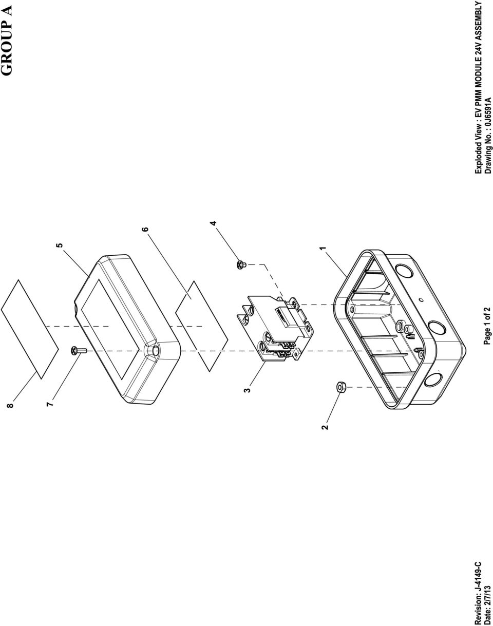
14 EXPLODED VIEW: EV PMM MODULE 4V ASSEMBLY DRAWING #: 0J659A APPLICABLE TO: ITEM PART# QTY. DESCRIPTION GROUP A 0H7377 ASSY BOTTOM COVER DLM NUT HEX /4-0 SS 3 0J6590 CONTACTOR P 40A 4V COIL 4 0H SCREW PPPH #0 X /4"LG 5 0H7649 COVER TOP CONTACTOR BOX DLM 6 0J6593 DECAL DLM MODULE 4V SERIAL 7 0H7646 SCREW PPPH #0 X 5/8"LG 8 0J6603 DECAL DLM 4V GENERAC () LUG RNGTNG INS 6-4X/4X.477 () LUG RNGTNG INS -0X/4X.598 () 0K355 5 LUG DIS FLAG -8AWG FE 90DEG () 0K54 BUSHING UNIVERSAL.875 DIA () BAG ZIP 3 X 4 POLY () NOT SHOWN NOTE: ITEMS 9 THRU TO BE PLACED INSIDE POLY ZIP BAG ITEM 3. REVISION: J-449-C PAGE OF DATE: /7/3
0 08787 3 LUG RNGTNG INS -0X/4X.598 () 0K355 5 LUG DIS FLAG -8AWG FE 90DEG () 0K54 BUSHING UNIVERSAL.")
Owner's Manual. Automatic Transfer Switch. This manual should remain with the unit.
 Owner's Manual Automatic Transfer Switch REFERENCE THE OWNER'S MANUAL SUPPLIED WITH THE GENERATOR WHEN USING THIS DOCUMENTATION. NOT INTENDED FOR USE IN CRITICAL LIFE SUPPORT APPLICATIONS. THIS PRODUCT
Owner s Manual. For Automatic Transfer Switch. 100-200 Amp, Service Entrance/Non-Service Entrance
 Owner s Manual For Automatic Transfer Switch 100-200 Amp, Service Entrance/Non-Service Entrance Model Numbers RTST100A3 RTSP100A3 RTST150A3 RTST200A3 RTSP200A3 MODEL NUMBER: SERIAL NUMBER: DATE PURCHASED:
Automatic Transfer Switch
 Automatic Transfer Switch Owner s Manual ATS Service Entrance HS Type Transfer Switch This manual should remain with the unit. IMPORTANT SAFETY INSTRUCTIONS SAVE THESE INSTRUCTIONS! Read the following
INSTALLATION INSTRUCTIONS
 LIGHTING CONTROL PANELS 4 AND 8 RELAYS INSTALLATION INSTRUCTIONS INSTALLATION OVERVIEW The installation instructions contained in this document are provided as a guide for proper and reliable installation.
Installation. Smart-UPS VT MGE Galaxy 3500. Maintenance Bypass Panel. 10-40 kva 400 V
 Installation Smart-UPS VT MGE Galaxy 3500 Maintenance Bypass Panel 10-40 kva 400 V Contents Safety.................................................. 1 Save these instructions...................................
HP UPS R1500 Generation 3
 HP UPS R1500 Generation 3 Installation Instructions Part Number 650952-001 NOTE: The rating label on the device provides the class (A or B) of the equipment. Class B devices have a Federal Communications
For 100 Amp Automatic Transfer Switch/Load Center Models: 10 Circuit, 12 Circuit and 16 Circuit. Installed with 7, 10, 13 and 16kW Generators.
 INSTALLATION GUIDE For s Residential Power Systems For 100 Amp Automatic Transfer Switch/Load Center Models: 10 Circuit, 12 Circuit and 16 Circuit. Installed with 7, 10, 13 and 16kW Generators. This Automatic
Wiser Panel Meter, Model Number WISERCTPM200 Installer s Guide
 Instruction Bulletin EAV85226 08/2014 Wiser Panel Meter, Model Number WISERCTPM200 Installer s Guide Retain for future use. Product Description Kit Contents The Wiser Panel Meter is for use in energy management
Use & Care Manual. Electric Tankless Water Heaters. With Installation Instructions for the Installer AP15447 (10/10)
") Use & Care Manual With Installation Instructions for the Installer Electric Tankless Water Heaters The purpose of this manual is twofold: one, to provide the installer with the basic directions and recommendations
Use & Care Manual With Installation Instructions for the Installer Electric Tankless Water Heaters The purpose of this manual is twofold: one, to provide the installer with the basic directions and recommendations
Union County Public Schools. Facilities Department. Electrical. Safe Work Practices
 1 Union County Public Schools Facilities Department Electrical Safe Work Practices 2 Purpose In accordance with OSHA Standards 1910.331-335, safety-related work practices shall be used by Union County
Single Phase Soft Starter
 Single Phase Soft Starter Installation & Operating Manual 6/02 Table of Contents Section 1 General Information................................................... 1 1 General Description................................................
ARCO Electric Products Installation and Maintenance Manual Low Voltage Automatic Power Factor Correction Capacitor Systems 2013
 ARCO Electric Products Installation and Maintenance Manual Low Voltage Automatic Power Factor Correction Capacitor Systems 2013 READ CAREFULLY These instructions are intended to cover good practices in
Advantium 2 Plus Alarm
 ADI 9510-B Advantium 2 Plus Alarm INSTALLATION AND OPERATING INSTRUCTIONS Carefully Read These Instructions Before Operating Carefully Read These Controls Corporation of America 1501 Harpers Road Virginia
PT-6000 Power Tower INSTALLATION MANUAL SPECIFICATIONS
 PT-6000 Power Tower INSTALLATION MANUAL 10.5 9.75 12 22.75 10.75 MAXIMUM SOIL HEIGHT: DO NOT ALLOW FILL TO EXCEED THIS LEVEL! 11.5 4 4 13 Optional PT-BASE for new installations or when previous 2000/6000
HM-W536 Install Guide
 HM-W536 Install Guide 9/13/2013 IMPORTANT SAFETY INSTRUCTIONS Warning - When using electrical devices, basic safety precautions should be followed to reduce the risk of fire, electrical shock or injury.
Installation Instructions for Alarm Module Kit A043F059
 Instruction Sheet 07-2013 Installation Instructions for Alarm Module Kit A043F059 1 Introduction The information contained within is based on information available at the time of going to print. In line
READ THIS MANUAL BEFORE PROCEEDING WITH THE INSTALLATION. FAILURE TO FOLLOW THE INSTALLATION INSTRUCTIONS MAY VOID YOUR WARRANTY!
 READ THIS MANUAL BEFORE PROCEEDING WITH THE INSTALLATION. FAILURE TO FOLLOW THE INSTALLATION INSTRUCTIONS MAY VOID YOUR WARRANTY! The main power to any existing system must be disconnected prior to the
LIEBERT VNSA Installation Sheet
 LIEBERT VNSA Installation Sheet Description The Liebert vnsa network switch is designed for connecting multiple Ethernet-ready devices and comes in various models. The unit may have: A Liebert icom display
Contractors Guide Central Inverter System Installation
 Contractors Guide Central Inverter System Installation Step By Step Procedures 2,200 Watt/VA 6 Step Installation 1. Mount Bottom Cabinet 2. Mount Top Cabinet 3. Install Batteries 4. Install Conduit 5.
MTE SERIES RLW. World REACTORS USER MANUAL PART NO. INSTR 030 REL. 090930. 2009 MTE Corporation
 MTE SERIES RLW World REACTORS USER MANUAL PART NO. INSTR 030 REL. 090930 2009 MTE Corporation IMPORTANT USER INFORMATION NOTICE MTE Series RLW reactors are components designed to improve the reliability
Electrical Wiring Methods, Components and Equipment for General Use. Approved for Public Release; Further Dissemination Unlimited
 Electrical Wiring Methods, Components and Equipment for General Use Approved for Public Release; Further Dissemination Unlimited At the completion of this unit you shall be able to: 1. Utilize section
OASIS-PLUS 120V READ ALL INSTRUCTIONS BEFORE OPERATING READ ALL INSTRUCTIONS BEFORE OPERATING OZONE IS A POWERFUL OXIDIZER AND MUST BE USED WITH CARE
 OASIS-PLUS 120V INFORMATION & OPERATING INSTRUCTIONS READ ALL INSTRUCTIONS BEFORE OPERATING READ ALL INSTRUCTIONS BEFORE OPERATING OZONE IS A POWERFUL OXIDIZER AND MUST BE USED WITH CARE 56041852 WARNING:
Step 1. Item 6. Item 1
 Voltage Regulators QD3/T350 Motor Replacement Kit Kit Number 57A63675100B Service Information S225-50-35 Contents General..................................... 1 Parts Supplied...............................
PowerFlex 700S and 700H Frame 12 DC Bus Connector Kit
 PowerFlex 700S and 700H Frame 12 DC Bus Connector Kit Installation Instructions This document provides instructions for the installation of a DC bus connector kit for PowerFlex 700S and 700H frame 12 drives
E2 Series Electric Furnaces
 E2 Series Electric Furnaces Service Manual Table of Contents Electrical Requirements... 10 Codes, Specifications Requirements... 10 Connection Supply Service Wires... 10 Furnace Sequence of Operation...
Installation and Operation Guide for PD5100 Automatic Transfer Switch
 Installation and Operation Guide for PD5100 Automatic Transfer Switch Member P r o gr e ssive Dynamics, Inc. 507 Industrial Rd Marshall, MI 49068 www.progressivedyn.com 2012 Progressive Dynamics, Inc.
TECHNICAL SUPPORT MANUAL 3 Phase Air Conditioner Component R2A3**GHR
 3 Phase Air Conditioner Component R2A3**GHR DANGER, WARNING, CAUTION, and NOTE The signal words DANGER, WARNING, CAU- TION, and NOTE are used to identify levels of hazard seriousness. The signal word DANGER
Part I - Installation
 400 Series Pressure and Differential Pressure Switches Types: H400, H402, H403, H400K, H402K, J400, J402, J403, J400K, J402K UNITED ELECTRIC CONTROLS Installation and Maintenance Instructions Please read
DC400 Dispensing Cutoff System
 DC400 Dispensing Cutoff System DC404 and DC406 Installation Instructions Franklin Fueling Systems 3760 Marsh Rd. Madison, WI 53718 USA Tel: +1 608 838 8786 800 225 9787 Fax: +1 608 838 6433 www.franklinfueling.com
CONTROL PANEL INSTALLATION INSTRUCTIONS. Single Phase Simplex Page 2-7. 3-Phase Simplex Page 8-13
 CONTROL PANEL INSTALLATION INSTRUCTIONS Single Phase Simplex Page 2-7 3-Phase Simplex Page 8-13 Single Phase Simplex SXL21=3, SXL24=3, SXH21=3, and SXH24=3 Manufactured by SJE-Rhombus Installation Instructions
WARNING: FAILURE TO FOLLOW THESE RULES MAY RESULT IN SERIOUS PERSONAL INJURY CAUTION: INSTALLATION LOCATION:
 Revision Level: 01 Revision Date: 07/07/2011 Please read all instructions carefully to help ensure a correct and SAFE installation of your Second Wind Ultraviolet Germicidal Air Purifier. Failure to do
Doorbell Intercom Security System
 Doorbell Intercom Security System POWER IN USE OFF A B C LOCK CALL TALK Installation Guide Model WHDB-301 EXPLANATION OF GRAPHIC WARNING SYMBOLS This symbol is intended to alert the user to the presence
! WARNING. McDonnell & Miller Installation & Maintenance Instructions MM-217(I) Series 150S and 157S (Snap Switch, All Models except 157S-RB-P)
 Series 150S and 157S (Snap Switch, All Models except 157S-RB-P)") Series 150S and 157S (Snap Switch, All Models except 157S-RB-P) Low Water Cut-Off/Pump Controllers For Steam Boilers and Other Level Control Applications McDonnell & Miller Installation & Maintenance Instructions
Series 150S and 157S (Snap Switch, All Models except 157S-RB-P) Low Water Cut-Off/Pump Controllers For Steam Boilers and Other Level Control Applications McDonnell & Miller Installation & Maintenance Instructions
SP4-LOC SAFEPATH4 REMOTE MICROPHONE AND LOCAL OPERATOR CONSOLE
 SP4LOC SAFEPATH4 REMOTE MICROPHONE AND LOCAL OPERATOR CONSOLE INSTALLATION AND OPERATION MANUAL MASS NOTIFICATION SYSTEM Part Number: P84767 Rev. A Copyright 2006 Cooper Wheelock, Inc. All rights reserved.
ATS Overhead Table Shelf System INSTRUCTION MANUAL
 ATS Overhead Table Shelf System INSTRUCTION MANUAL ATS Overhead Table Shelf System Instruction Manual Warranty Newport Corporation warrants this product to be free of defects in material and workmanship
On/Off Relay Switch and 3-Way Switch Kit
 45637/45638 Wireless Lighting Control On/Off Relay Switch and 3-Way Switch Kit marthome Control the On/Off status of permanently installed lighting, fans and more! www.lowes.com/iris 2012 JASCO Made in
Air-cooled Generator Battery Charger Installation Guidelines
 Air-cooled Generator Battery Charger Installation Guidelines Table of Contents Table of Contents...Inside Front Cover Section 1 General Information... IFC 1.1 Introduction...IFC 1.2 Battery Charger Compatibility...
Installer s Guide WARNING: 18-GJ11D1-2. Ultraviolet (UV-C) Lamp Kit for 2-5 Ton Air Handlers HAZARDOUS VOLTAGE - DISCONNECT POWER BEFORE SERVICING
 Lamp Kit for 2-5 Ton Air Handlers HAZARDOUS VOLTAGE - DISCONNECT POWER BEFORE SERVICING") Installer s Guide 18-GJ11D1-2 : Models: BAYUVCLK001-40 Watt, 2 Lamp NOTE: A BAYCC24VK01 can be installed for Series 8 Air Handlers to extend the life of the lamp. This accessory kit will disable the lamp
Installer s Guide 18-GJ11D1-2 : Models: BAYUVCLK001-40 Watt, 2 Lamp NOTE: A BAYCC24VK01 can be installed for Series 8 Air Handlers to extend the life of the lamp. This accessory kit will disable the lamp
 0150506194 C Limited 2nd through 5th Year Functional Parts Warranty During the 2nd through 5th year,haier will provide functional parts which prove to be defective due to workmanship
All work must conform to the National Electric Code, latest edition, and all other applicable codes and regulations.
 DIVISION 16 ELECTRICAL SECTION 16100 - ELECTRICAL PART 1 - GENERAL SCOPE All electrical work as shown on the drawings and as necessary to provide a complete electrical system. Include primary service,
AMERBRITE UNDERWATER WHITE LED POOL LAMP
 AMERBRITE UNDERWATER WHITE LED POOL LAMP FOR USE ONLY WITH PENTAIR AMERLITE LUMINAIRE INSTALLATION AND USER S GUIDE IMPORTANT SAFETY INSTRUCTIONS READ AND FOLLOW ALL INSTRUCTIONS SAVE THESE INSTRUCTIONS
with MERCURY FREE 1 HP Relays ! WARNING Before using this product read and understand instructions.
 B Installation & Maintenance Instructions MM-414 Series 150E and 157E Low Water Cut-Off/Pump Controllers For Steam Boilers and Other Level Control Applications A Typical Applications: Primary or secondary
PART 8: FIELD WIRING. n WARNING NOTICE. Boiler Manual
 PART 8: FIELD WIRING A. INSTALLATION MUST COMPLY WITH: 1. National Electrical Code and any other national, state, provincial or local codes or regulations. 2. In Canada, CSA C22.1 Canadian Electrical Code
SECTION 26 09 26 LOW VOLTAGE LIGHTING CONTROLS
 SECTION 26 09 26 LOW VOLTAGE LIGHTING CONTROLS PART 1 - GENERAL 1.01 RELATED DOCUMENTS: A. The Conditions of the Contract and applicable requirements of Division 1, "General Requirements", and Section
12-Volt 10-Amp Regulated Power Supply
 22-506.fm Page 1 Friday, August 6, 1999 12:55 PM Cat. No. 22-506 OWNER S MANUAL Please read before using this equipment. 12-Volt 10-Amp Regulated Power Supply 22-506.fm Page 2 Friday, August 6, 1999 12:55
IMPORTANT: BEFORE INSTALLING ANY HEATING TERMINAL UNIT TO A DOMESTIC WATER HEATER, CONSULT THE LOCAL PLUMBING CODES.
 QUIET-ONE Environmental Products 2000 Kickspace Heater Series Models: KS 2004, KS 2006 KS 2008, KS 2010 INSTALLATION OPERATING MAINTENANCE Please read these instructions thoroughly before beginning your
ScreenLogic Wireless Connection Kit. Installation Guide. pool/spa control system
 pool/spa control system ScreenLogic Wireless Connection Kit Installation Guide P/N 520663 - Rev B 8 Technical Support Contact Technical Support at: Sanford, North Carolina (8 A.M. to 5 P.M.) Phone: (800)
TSn SERIES Surge Protective Device
 Page: 1 of 8 TSn SERIES Surge Protective Installation & Operation Manual 3621 Saunders Avenue www.systems.us Ph 804.355.1100 Richmond, VA 23227 4354 [email protected] Fax 804.355.8900 Page: 2 of 8 Quick
Packaged Terminal Air Conditioner Wall Sleeve Installation
 Installation & Maintenance Data IM 1196 Group: PTAC Part Number: 910141799 Date: October 2013 Packaged Terminal Air Conditioner Installation x 42" PGAN with Top-Mounted Hydronic Heat Note: Installation
Chromalox. Installation, Operation. Portable Industrial Unit Blower Air Heater Type DRA RENEWAL PARTS IDENTIFICATION
 Chromalox Installation, Operation RENEWAL PARTS IDENTIFICATION Portable Industrial Unit Blower Air Type DRA and DIVISION SALES REFERENCE DATE SECTION (Supersedes P-) PF-) NOVEMBER, 00 DRA PF- -0-00 Specifications
RAY-MAX Integrated Solar Power Strip
 RAY-MAX Integrated Solar Power Strip 600008, 600009, 600010, 600208, 600209, 600210 Owner s Manual NEXTRONEX, INC. Revision Date: 10/27/14 Contents 1. Safety Instructions... 3 2. General Equipment Warnings...
ELECTRICAL SAFETY. The standard unit for measuring electrical current.
 ELECTRICAL SAFETY Introduction The following sections provide general safety guidelines and procedures for electrical safety. This chapter covers the following topics: TOPIC PAGE General Electrical Safety
543-0032-00, 943-0032-00. User s Manual
 543-0032-00, 943-0032-00 User s Manual 1 Comfort Alert Diagnostics Faster Service And Improved Accuracy The Comfort Alert diagnostics module is a breakthrough innovation for troubleshooting heat pump and
For Models #6-5001, #6-7501, #10-7501 & #10-12K1
 EmerGen Switch Manual Transfer Switch Manufactured by CONNECTICUT ELECTRIC SWITCH MFG. CO. 1-800-730-2557 OWNER S MANUAL & INSTALLATION INSTRUCTIONS For Models #6-5001, #6-7501, #10-7501 & #10-12K1 PLEASE
ELECTRICAL GUIDELINES FOR SINGLE-FAMILY HOME OWNERS:
 ELECTRICAL GUIDELINES FOR SINGLE-FAMILY HOME OWNERS: Chapter 12 of the Burlington Code of ordinances allows owner occupants of single family homes to do their own wiring if they choose. If you choose to
SECTION 26 09 13 - POWER MONITOR FOR ELECTRICAL, STEAM CONDENSATE, AND WATER PART I - GENERAL
 SECTION 26 09 13 - POWER MONITOR FOR ELECTRICAL, STEAM CONDENSATE, AND WATER PART I - GENERAL 1.1 SUMMARY A. This section describes the requirements for the installation of Power Monitors and associated
RayClic Connection System Installation Instructions
 F M -W RayClic Connection System Installation Instructions RayClic WARNING: Shock Hazard 718K Pipe Heating Cable with HWAT, IceStop, also Listed De-icing and and XL-Trace heating Snow Melting Equipment
INSTALLATION INSTRUCTIONS MULTI-MOUNT KIT Part Number: 75330 Application: Warn HP PowerPlant P/N 71800
 INSTALLATION INSTRUCTIONS MULTI-MOUNT KIT Part Number: 75330 Application: Warn HP PowerPlant P/N 71800 Your safety, and the safety of others, is very important. To help you make informed decisions about
UHIR Series. Horizontal or Vertical Mounting Industrial / Commercial Electric Unit Heater. Owner s Manual
 UHIR Series Horizontal or Vertical Mounting Industrial / Commercial Electric Unit Heater Owner s Manual This manual covers installation, maintenance and repair parts. Read carefully before attempting to
Installation and Operation Guide PD4600 Series Converter Replacement
 Installation and Operation Guide PD4600 Series Converter Replacement Extended warranties are available for purchase at www.progressivedyn.com Member Thank you for selecting Progressive Dynamics as your
JANUS INTERNATIONAL CORPORATION INSTALLATION INSTRUCTIONS Pantheon Mini Operator
 JANUS INTERNATIONAL CORPORATION INSTALLATION INSTRUCTIONS Pantheon Mini Operator The Janus Pantheon mini operator does not typically require the provision of any additional site requirements other than
Mini-led spotlight with magnetic base
 Mini-led spotlight with magnetic base Model 95799 Assembly And Operation Instructions Due to continuing improvements, actual product may differ slightly from the product described herein. 3491 Mission
Introduction. Safety Guidelines. Part Numbers. Operation and Maintenance Manual. Operation and Maintenance Manual
 Operation and Maintenance Manual Introduction Read all instructions thoroughly. Installation of the OilTector must comply with all Federal, State and Local Codes, Regulations and Practices. The OilTector
Instruction Bulletin. MCS025 Sync-Check Module Installation Sheet
 Instruction Bulletin 63230-216-244B1 LaVergne, TN, USA MCS025 Sync-Check Module Installation Sheet Retain for future use. DANGER HAZARD OF ELECTRIC SHOCK, EXPLOSION, OR ARC FLASH Only qualified electrical
Installation Instructions
 Installation Instructions Accessory Ultraviolet (UV) Germicidal Lamp 1 & 2 Lamp Models 115-v & 208/230-v UV Lamp C03009 Fig. 1 Two Lamp Model UV Lamp NOTE: Read the entire instruction manual before starting
Freeze Protection Thermostats MODELS SST 2. Installation and Operation Manual
 Freeze Protection Thermostats MODELS SST 2 Part Number 22744 MANUAL We Manage Heat Installation and Operation Manual Environmental Technology, Inc. 1850 N Sheridan Street South Bend, Indiana 46628 (574)
Requirements for Electrical Installations
 ARTICLE 110 Requirements for Electrical Installations INTRODUCTION TO ARTICLE 110 REQUIREMENTS FOR ELECTRICAL INSTALLATIONS Article 110 sets the stage for how you ll implement the rest of the NEC. This
This equipment has been tested and found to comply with the limits for a Class B digital device, pursuant to part 15 of the FCC Rules.
 Power Max Level 2 Charging Station en Installation and Operating Instructions This equipment has been tested and found to comply with the limits for a Class B digital device, pursuant to part 15 of the
Owner s Manual & Safety Instructions
 Owner s Manual & Safety Instructions Save This Manual Keep this manual for the safety warnings and precautions, assembly, operating, inspection, maintenance and cleaning procedures. Write the product s
Operating Instructions
 Operating Instructions Series L 000 Cord Reels Model Numbers: L 000 L 0 0 L 0 B L 0 X L 00 L A X L 0 L 0 0 L 00 L 0 L 0 B L 0 0 X L 00 L 0 A L 0 X IMPORTANT Read this manual carefully before installing,
OPERATOR S MANUAL 18 VOLT, 1 HOUR CHARGER
 OPERATOR S MANUAL 18 VOLT, 1 HOUR CHARGER P110 Your battery charger has been engineered and manufactured to Ryobi s high standard for dependability, ease of operation, and operator safety. When properly
Your safety and the safety of others are very important.
 NATURAL GAS TO PROPANE CONVERSION KIT 090 INSTALLATION INSTRUCTIONS FOR ALTITUDES 0 -,00 FT. ONLY PROPANE CONVERSION KIT SAFETY... INSTALLATION REQUIREMENTS... Tools and Parts... LP Gas Requirements...
SUBJECT: How to wire a motor starter Number: AN-MC-004 Date Issued: 2/08/2005 Revision: Original
 SUBJECT: How to wire a motor starter Number: AN-MC-004 Date Issued: 2/08/2005 Revision: Original A motor starter is a combination of devices to allow an induction motor to start, run and stop according
INSTALLATION MANUAL ELECTRIC RANGE. Please read these instructions thoroughly before installing and operating the range.
 ENGLISH ESPAÑOL INSTALLATION MANUAL ELECTRIC RANGE Please read these instructions thoroughly before installing and operating the range. LRE3025ST LRE3085ST LRE3083ST LRE3083SB LRE3083SW LRE3021ST LDE3037ST
33.6W Power over Ethernet Waterproof Adapter PoE Plus Single Port Injector for Outdoor Application
 33.6W Power over Ethernet Waterproof Adapter PoE Plus Single Port Injector for Outdoor Application Features Compliant with the IEEE802.3at Standard -40 to +60 C Temperature Range Diagnostic LEDs Full Protection
Seven function digital multimeter
 Seven function digital multimeter 98025 Set up And Operating Instructions Distributed exclusively by Harbor Freight Tools. 3491 Mission Oaks Blvd., Camarillo, CA 93011 Visit our website at: http://www.harborfreight.com
INTELLICHLOR POWER CENTER FOR USE WITH INTELLILCHLOR CHLORINE GENERATOR MODEL IC20, IC40 & IC60
 INTELLICHLOR POWER CENTER FOR USE WITH INTELLILCHLOR CHLORINE GENERATOR MODEL IC20, IC40 & IC60 INSTALLATION AND USER S GUIDE IMPORTANT SAFETY INSTRUCTIONS READ AND FOLLOW ALL INSTRUCTIONS SAVE THESE INSTRUCTIONS
Generator Transfer Switch Model # HTS15-AUTO
 Generator Transfer Switch Model # HTS15-AUTO Congratulations on your purchase of our Single Circuit Generator Transfer Switch, We hope this meets and exceeds your expectations. If at anytime you have any
Square D Clipsal DIN-Rail Four-Channel Auxiliary Input Unit
 Square D Clipsal DIN-Rail Four-Channel Auxiliary Input Unit SLCLE5504AUX for Use with Wired C-Bus Networks Instruction Bulletin Retain for future use. Square D Clipsal DIN-Rail Four-Channel Auxiliary Input
EPM3. Phase Sequence and Motor Rotation Tester. Users Manual
 EPM3 Phase Sequence and Motor Rotation Tester Users Manual 1 L1 L2 L3 2 3 A B C CAT 600V 3-PHASE TESTER 5 TEST M1 M2 BATT M3 EPM3 MOTOR ROTATION TESTER EPM3 MOTOR ROTATION DETERMINED WHILE FACING MOTOR
Roof Top Air Conditioner INSTALLATION AND OPERATING INSTRUCTIONS
 Roof Top Air Conditioner INSTALLATION AND OPERATING INSTRUCTIONS Ducted System RECORD THIS UNIT INFORMATION FOR FUTURE REFERENCE: Model Number: Serial Number: Date Purchased: This manual must be read and
ELECTRIC METERING COMMERCIAL & INDUSTRIAL
 ELECTRIC METERING COMMERCIAL & 1.0 INDEX 1.0 INDEX 2.0 SCOPE 3.0 GENERAL REQUIREMENTS 4.0 METER LOCATIONS 5.0 UNDERGROUND TERMINATIONS 6.0 METERING TRANSFORMER ENCLOSURES 7.0 SINGLE CUSTOMER METER INSTALLATIONS
MACBlower Model Number: MAC40R MAC60R MAC80R MAC100R. MAC120R MAC150R MAC 200R Serial # www.macblowers.com
 MACBlower Model Number: MAC40R MAC60R MAC80R MAC100R MAC120R MAC150R MAC 200R Serial # Fuji Clean USA 41-2 Greenwood Road Brunswick, Maine 04011 207-406-2729 www.macblowers.com MACBlowers The Intelligent
Metallic and Non-Metallic Air Conditioning Disconnects. A Complete Family of. Disconnects with Exclusive Time Saving Features
 Metallic and Non-Metallic Air Conditioning Disconnects A Complete Family of Disconnects with Exclusive Time Saving Features Enclosed Molded Case Disconnect Switch Not-Fusible The preferred molded case
HEAT WAVE DUCT KIT KIT # 946-568
 HEAT WAVE DUCT KIT KIT # 946-568 www.regency-fire.com Approved for use with Models: P36, P36D, P42, P48, P90, P95, L676S, P33S & HZ54 WARNING: Improper installation, adjustment, alteration, service or
CUSTOM AUXILIARY FORWARD LIGHTING KIT
 -J0 REV. 0--0 CUSTOM AUXILIARY FORWARD LIGHTING KIT GENERAL Kit Number -0, 0000 Models This Custom Auxiliary Lighting Kit adds lamps and turn signals to 00 and later FLHX model motorcycles. Additional
Sense Components. Sense monitor. Antenna assembly. External mounting kit Current sensors. Download the Sense app. Go to sense.com/app.
 Sense Components Sense monitor Antenna assembly External mounting kit Current sensors Download the Sense app. Go to sense.com/app Power cable Technical Specifications Sense is a home energy monitoring
Electrical for Detached Garages: Updated Feb 19, 2016 for 2015 CE Code in force Jan. 1, 2016. Underground branch circuit feeding a detached garage:
 Electrical for Detached Garages: Updated Feb 19, 2016 for 2015 CE Code in force Jan. 1, 2016 * Garage construction requires permits (electrical, building) * Permits must be applied for at the time. * Dial
Installation. Smart-UPS VT and MGE Galaxy 3500. Maintenance Bypass Panel with Power Distribution (wall-mount) 10-30 kva 208 V
 10-30 kva 208 V") Installation Smart-UPS VT and MGE Galaxy 3500 Maintenance Bypass Panel with Power Distribution (wall-mount) 10-30 kva 208 V Contents Safety... 1 SAVE THESE INSTRUCTIONS...............................
Installation Smart-UPS VT and MGE Galaxy 3500 Maintenance Bypass Panel with Power Distribution (wall-mount) 10-30 kva 208 V Contents Safety... 1 SAVE THESE INSTRUCTIONS...............................
SIMATIC S7-300. Getting Started for First Time Users. Order No.: 6ZB5310-0NC02-0BA0 04/2007 A5E01094750-01
 SIMATIC S7-300 Getting Started for First Time Users Order No.: 6ZB5310-0NC02-0BA0 04/2007 A5E01094750-01 Safety Guidelines This manual contains notices you have to observe in order to ensure your personal
G670 Intermittent Pilot Ignition Controls
 Installation Sheets Manual 121 Gas Combustion Combination Controls and Systems Section G Technical Bulletin Issue Date 0300 Intermittent Pilot Ignition Controls Figure 1: Intermittent Pilot Ignition Control
DLP-PU/E Instruction Manual
 Instruction Manual BEFORE USING THE POWER SUPPLY UNIT Pay attention to all warnings and cautions before using the unit. Incorrect usage could lead to an electrical shock, damage to the unit or a fire hazard.
ELECTRIC CONVECTION BUILT-IN OVEN
 ENGLISH ESPAÑOL FRANÇAIS INSTALLATION MANUAL ELECTRIC CONVECTION BUILT-IN OVEN Please read these instructions thoroughly before installing and operating the oven. LWS3081ST LWD3081ST LSWS305ST LSWD305ST
BroadBand PowerShield. User Manual
 BroadBand PowerShield User Manual 990-0375G 12/2006 Chapter 1 General Information The PowerShield provides a power source for broadband telephony and other DC applications. Safety This Safety Guide contains
Infrarot-Bewegungsmelder IP44
 Infrarot-Bewegungsmelder IP44 infrared motion sensors IP44 ODA (weiß) slim ODA (schwarz) slim 95174 96000 ODA (weiß) ODA (schwarz) 95175 96001 Betriebsanleitung User s Manual User s Manual infrared motion
DRM75A 230V 20/100A DIN rail single phase two wire energy meter
 DRM75A 230V 20/100A DIN rail single phase two wire energy meter 1.1 Safety instruction 1.2 Foreword 1.3 Performance criteria 1.4 Specifications 1.5 Basic errors 1.6 Description 1.7 Dimensions 1.8 Installation
7 FUNCTION DIGITAL MULTIMETER
 7 FUNCTION DIGITAL MULTIMETER 90899 OPERATING INSTRUCTIONS 3491 Mission Oaks Blvd., Camarillo, CA 93011 Visit our Web site at http://www.harborfreight.com Copyright 2004 by Harbor Freight Tools. All rights
Installation Instructions
 H5HK Series Installation Instructions 3 Phase Electric Heater Kits 7.5 and 0 TON Package A/C Systems Description Installation of 08/40V and 480V H5HK 3 Phase Heater Kits in 7.5 and 0 TON Packaged Air Conditioners.
8" BENCH GRINDER OWNER'S MANUAL
 8" BENCH GRINDER OWNER'S MANUAL WARNING: Read carefully and understand all INSTRUCTIONS before operating. Failure to follow the safety rules and other basic safety precautions may result in serious personal
Parallel Redundant Uninterruptible Power Supply
 9 315 Parallel Redundant Uninterruptible Power Supply Installation/Operation Manual 164202013 Rev. D ------------------------------------------------------------------------ ------------------------------------------------------------------------