GEM APPLICATION USER S GUIDE KAntrak 1700
|
|
|
- Emil Carroll
- 9 years ago
- Views:
Transcription

1 GEM APPLICATION USER S GUIDE KAntrak 1700
2 Buffer Page Hard covers must be printed on top side only
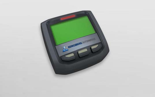
3 Gem Application User's Guide Thank you for choosing the KAntrak 1700 display. These pages provide a brief introduction to the KAntrak 1700 Generic Engine Monitoring (GEM). For more information please see the web site: Section/Contents Page 1. Menu Browsing Display Modes Settings Menu Supported Parameters... 13

4 1. Menu Browsing The KAntrak 1700 unit has only three(3) buttons for different features selection. For that reason a dynamic style menu system has been implemented. During normal operation, the buttons have no specific functions. When pressing any button once, a dynamic pop-up menu appears. The menu contains some functions icons aligned above the associated button. The user selects the required function from the displayed menu. After a few seconds, the menu will be hidden. page 2
5 2. Display Modes The GEM application is used to display live parameters and diagnostic trouble codes available on the J1939 bus. By pressing the button the user can scroll through the available parameters on the vehicle's network. A complete list of supported parameters are listed into the Supported Parameters section. At any time in any display mode, the user can select the tool to access the setting menu and change the current display mode. See Settings Menu section. 2.1 Single Screen This mode is used to monitor one parameter at a time. The screen also displays the associated parameter icon, the description, the units and a bar graph. page 3


6 Bar graph Limits adjust The Single Screen mode has a special function for bar graph limits minimum and maximum adjustment. This can be done by selecting the related parameter and then pressing the button. The unit should now display the bar graph limits adjust mode. Use +/- for adjustment and select Exit when finished. page 4
 parameters selected by the user.")
7 2.2 Dual Screen The Dual Screen mode is used to monitor two parameters at a time. The screen also displays the associated parameter icon and units. 2.3 Multi Screen The Multi Screen mode is used to monitor a list of four(4) parameters selected by the user. Every item is listed with its associated icon and units. page 5

8 2.4 DTC Screen The DTC Screen mode is used to display Data Trouble Codes according to SAE J The main screen displays all vehicle active faults (DM1) and occurs faults (DM2). A bright bulb means that the current fault is active while a dark bulb means that the current fault has occured. The header contains the total active/inactive faults, the associated SPN and FMI and the numbers of occurances as well. page 6
, the FMI")
 and the related node source address (SRC) will then")
9 DTC Detailed info For a given DTC, the user may select the? function from the menu. A detailed screen of the selected DTC including the SPN description (Header), the FMI Description (Header), the fault status (Status), the SPN Number (SPN), the FMI Number (FMI), the total number of occurrences (OCC) and the related node source address (SRC) will then appear. page 7

10 3. Settings Menu 3.1 Display Mode This setting is used to select the current display mode: Single, Dual, Multi or Dtc. Display modes are explained into the section Language The user can select various supported languages for interface display. 3.3 Fuel Level Source With Input mode selected, the device reads the fuel level signal from the discrete sensor input. In this mode, the local information is also broadcasted on the J1939 network to other nodes. page 8
11 In Network mode, the device reads the fuel signal from the associated PGN on the J1939 network. 3.4 Alarm Output When enabled the external alarm device is turned on when a new active fault (DM1) occurs. The alarm is turned off when all new active faults have been acknowledged. In Disable mode, the external device is never activated. 3.5 Demo Mode By enabling this option, the users can test the unit even though is not connected to the vehicle network. The network feed is replaced by a simulation lead that allows the user to display every supported SPNs. Moreover some Data Trouble Codes (DTC) are also generated. This is disabled by default at power on. 3.6 Tier4 Popout Mode This option enables pop-up monitoring of the selective catalytic reduction (SCR) parameters available in J1939. When enabled, any status change will appear in a pop-up window even if the main window does not monitor the TIER4 parameters. page 9

12 3.7 Contrast /Backlight Contrast and backlight commands according to the user's preferences. 3.8 Units The system supports many combinations of units depending on the user's preferences. Distance, Pressure and Volume units could be selected independently. Default settings correspond to all other measurements units. 3.9 Faults Clear This submenu is used to send a request to every modules on the vehicle to clear all occured faults (DM2). page 10
13 3.10 Fuel Tank Calibration This submenu is related to the discrete fuel input calibration. By doing the calibration sequence, the user can calibrate the fuel sender response for any custom tank in three(3) points. The best way to do this is to start with an empty thank and fill it with fuel during the process. The bargraph level represents the resistance signal value as read from the discrete input. The response profile may be different according to the sender characteristics. page 11
14 3.11 Factory settings This is intended to turn the unit back to the original factory settings. All current setttings will be lost. page 12
15 4. Supported Parameters Supported parameters as defined into SAE J SPN # PGN # Description Icon Pneumatic Supply Pressure Engine Intercooler Temperature Wheel-Based Vehicle Speed Accelerator Pedal Position Engine Percent Load At Current Speed Engine Fuel Delivery Pressure Fuel Level Engine Oil Level Engine Oil Pressure page 13
16 SPN # PGN # Description Icon Engine Intake Manifold #1 Pressure Engine Intake Manifold #1 Temperature Engine Air Inlet Pressure Engine Air Filter 1 Differential Pressure Barometric Pressure Engine Coolant Pressure Engine Coolant Temperature Engine Coolant Level Net Battery Current Alternator Current Transmission Oil Pressure page 14
17 SPN # PGN # Description Icon Keyswitch Battery Potential Charging System Potential (Voltage) Battery Potential / Power Input Engine Air Inlet Temperature Engine Exhaust Gas Temperature Engine Fuel Temperature Engine Oil Temperature Engine Turbocharger Oil Temperature Transmission Oil Temperature Engine Fuel Rate Engine Instantaneous Fuel Economy page 15
18 SPN # PGN # Description Icon Engine Average Fuel Economy Engine Speed Transmission Output Shaft Speed Total Vehicle Hours Engine Total Hours of Operation Auxiliary Temperature Driver's Demand Engine - Percent Torque Actual Engine - Percent Torque Navigation-Based Vehicle Speed Transmission Current Gear Transmission Selected Gear page 16
19 SPN # PGN # Description Icon Estimated Percent Fan Speed Total ECU Distance Engine Wait to Start Lamp Auxiliary Pressure # Catalyst Tank Level Hydraulic Pressure Catalyst Tank Temperature Aftertreatment 1 Exhaust Gas Temperature 1 (upstream) Aftertreatment 1 Exhaust Gas Temperature 3 (downstream) 3697 * Particulate Trap Lamp Command 3700 * Particulate Trap Active Regeneration Status page 17
20 SPN # PGN # Description Icon 3701 * Particulate Trap Status 3703 * Particulate Trap Active Regeneration Inhibited Due to Inhibit Switch Particulate Filter 1 Soot Load Percent Particulate Filter 1 Ash Load Percent (*) See section 4.1 page 18
21 4.1 Tier 4 specific display For SCR parameters (SPN# 3697, 3700, 3701 and 3703), the regeneration status is presented in 3 columns as follows when monitored in the main screen. When monitored by pop-up, the status will be labeled. Not Needed Request Level Warning Level Service Level Stop Level Not Available Unknown Not Inhibited Inhibited Unknown Not Active Active Needed Unknown page 19
22 Buffer Page Hard covers must be printed on top side only

23 Kongsberg Automotive: Christopher Martin Road Basildon, Essex England SS14 3ES Tel: +44(0) Fax: +44(0) , 28e Rue Grand-Mère (Qc) Canada G9T 7E9 Tel: (819) Fax: ( Kongsberg Automotive Specifications subject to change without notice. Any trademark used are recognised and are the property of their respective owners. Part Number: AC1938 (P03552A02) May 2011
Fault codes DM1. Industrial engines DC09, DC13, DC16. Marine engines DI09, DI13, DI16 INSTALLATION MANUAL. 03:10 Issue 5.0 en-gb 1
 Fault codes DM1 Industrial engines DC09, DC13, DC16 Marine engines DI09, DI13, DI16 03:10 Issue 5.0 en-gb 1 DM1...3 Abbreviations...3 Fault type identifier...3...4 03:10 Issue 5.0 en-gb 2 DM1 DM1 Fault
Signature and ISX CM870 Electronics
 Signature and ISX CM870 Electronics Cummins West Training Center System Description General Information The Signature and ISX CM870 engine control system is an electronically operated fuel control system
Note: This information obtained from internet sources and not verified- use at your own risk!!!!
 Cummins Engine Diagnostic Fault Codes for 2003 and later engines (generally for 2004 and later Alpines; see page 13 for earlier engine diagnostic codes): Note: This information obtained from internet sources
Diagnostic Fault Codes For Cummins Engines
 Section - Diagnostic Fault Codes For Cummins Engines Applies to Engine Models T, T, QSL T, QSM, QS, QSK9, QSK, QST, QSK//8 Note: These fault codes are current at date of publication. Always refer to engine
Service Information Trucks
 Service Information Trucks Group 28 Release2 Engine Control Module (ECM), Diagnostic Trouble Code (DTC), Guide 2010 Emissions CHU CXU GU TD 89047073 Foreword The descriptions and service procedures contained
Service Manual Trucks
 Service Manual Trucks Group 36 Vehicle Electronic Control Unit (MID 144), Diagnostic Trouble Code (DTC), Guide From build date 1.2007 PV776-88951780 Foreword The descriptions and service procedures contained
The Aftertreatment System Technician's Guide has been revised.
 NUMBER: 2 ATS 07 S.M. REF.: Listed in Table 1 ENGINE: ATS DATE: April 2007 SUBJECT: UPDATES TO AFTERTREATMENT SYSTEM TROUBLESHOOTING PUBLICATION: 7SE63 The Aftertreatment System Technician's Guide has
Introduction to Electronic Signals
 Introduction to Electronic Signals Oscilloscope An oscilloscope displays voltage changes over time. Use an oscilloscope to view analog and digital signals when required during circuit diagnosis. Fig. 6-01
RA Automotive. Silver Scan-Tool for the testing of OBD functionality. Peter Stoß Senior Manager RA Automotive. Mai 2008
 RA Automotive Silver Scan-Tool for the testing of OBD functionality Peter Stoß Senior Manager RA Automotive RA Consulting GmbH Zeiloch 6a D-76646 Bruchsal Tel +49 (0)7251 3862-0 Fax +49 (0)7251 3862-11
Electronic Power Control
 Service. Self-Study Programme 210 Electronic Power Control Design and Function With the Electronic Power Control system, the throttle valve is actuated only by an electric motor. This eliminates the need
Diagnostic Trouble Code (DTC) Charts
 Charts") Diagnostic Trouble Code (DTC) Charts Note: Before proceeding to the Pinpoint Test, refer to the Diagnostic Trouble Code (DTC) Descriptions for additional information to assist in diagnosis. 6.0L Diesel
Diagnostic Trouble Code (DTC) Charts Note: Before proceeding to the Pinpoint Test, refer to the Diagnostic Trouble Code (DTC) Descriptions for additional information to assist in diagnosis. 6.0L Diesel
USER MANUAL OPERATION AND USE OF CAR WITH. Diego G3 / NEVO SEQUENTIAL GAS INJECTION SYSTEM
 USER MANUAL OPERATION AND USE OF CAR WITH Diego G3 / NEVO SEQUENTIAL GAS INJECTION SYSTEM Page 2 z 7 Table of contents 1. STARTING THE ENGINE... 3 2. CONTROL PANEL... 3 2.1 Indication of the current level
G-100/200 Operation & Installation
 G-100/200 Operation & Installation 2 Contents 7 Installation 15 Getting Started 16 GPS Mode Setup 18 Wheel Sensor Mode Setup 20 Fuel Calibration 23 Basic Operation 24 Telemetery Screen 27 Entering a Distance
EMR 3 CAN BUS specification
 EMR 3 CAN BUS specification Version 11-3 Overview 1. SAE J1939-Standard CAN Messages... 3 1.1. EEC1:... 3 1.2. EEC2:... 5 1.3. Engine Temperature:... 6 1.4. Engine Fluid Level / Pressure:... 7 1.5. Inlet
V-MAC III Fault Assignments
 V-MAC III Fault Assignments ELECTRICAL FAULTS Stp Circuit Failure Blink Sequence 4 Engine Oil Pressure Low Voltage / Open 1 1 P 100 4 128/143 4 Engine Oil Pressure High Voltage 1 1 P 100 3 128/143 9 Barometric
I n s t r u m e n t a t i o n
 I n s t r u m e n t a t i o n Overview The 2008 Blue Bird Vision instrument cluster is a single unit containing all electronic guages manufactured by Stoneridge. In addition to gauges, the instrument panel
INSTRUMENT PANEL. 1995 Volvo 850 DESCRIPTION & OPERATION. 1995-96 ACCESSORIES & EQUIPMENT Volvo Instrument Panels
 INSTRUMENT PANEL 1995 Volvo 850 1995-96 ACCESSORIES & EQUIPMENT Volvo Instrument Panels 850 WARNING: When working around steering column and before performing repairs, disconnect and shield battery ground
DTC Database (OBD-II Trouble Codes)
") Auto Consulting S.a.s di Cofano A. & C. Attrezzature diagnostiche Elaborazioni elettroniche Formazione tecnica DTC Database (OBD-II Trouble Codes) Definitions for generic powertrain diagnostic trouble
Auto Consulting S.a.s di Cofano A. & C. Attrezzature diagnostiche Elaborazioni elettroniche Formazione tecnica DTC Database (OBD-II Trouble Codes) Definitions for generic powertrain diagnostic trouble
ON-Board Diagnostic Trouble Codes
 ON-Board Diagnostic Trouble Codes The list below contains standard diagnostic trouble codes (DTC s) that are used by some manufacturers to identify vehicle problems. The codes provide below are generic
Electronic Controls / LCD Display
 Operator s manual Read these instructions carefully and make sure you understand them before using the FS 6600 D / FS 8400 D. FS 6600 D, FS 6800 D, FS 8400 D, FS 9900 D Manual del operador Lea cuidadosamente
COMMON RAIL SYSTEM (CRS) SERVICE MANUAL: Operation
 SERVICE MANUAL: Operation") ISUZU ELF 4HK1/4JJ1 Engine COMMON RAIL SYSTEM (CRS) SERVICE MANUAL: Operation Issued : June 2007 Revised : July 2009 00400601EA 2009 DENSO CORPORATION All rights reserved. This material may not be reproduced
ISUZU ELF 4HK1/4JJ1 Engine COMMON RAIL SYSTEM (CRS) SERVICE MANUAL: Operation Issued : June 2007 Revised : July 2009 00400601EA 2009 DENSO CORPORATION All rights reserved. This material may not be reproduced
Volvo Vehicle Communications Software Manual
 Volvo Vehicle Communications Software Manual August 2013 EAZ0025B47A Rev. C Trademarks Snap-on is a trademark of Snap-on Incorporated. All other marks are trademarks or registered trademarks of their respective
E - THEORY/OPERATION
 E - THEORY/OPERATION 1995 Volvo 850 1995 ENGINE PERFORMANCE Volvo - Theory & Operation 850 INTRODUCTION This article covers basic description and operation of engine performance-related systems and components.
Operating Instructions Display, graphic T3014418
 Operating Instructions Display, graphic T3014418 Introduction... 1 Display, general... 1 Location and content of display... 2 Display control stalk... 3 Display menus... 4 Display symbols... 7 Alarm,
RETAINS STEERING WHEEL CONTROLS, SYNC MEDIA PLAYER, SYNC BLUETOOTH AND MORE!
 Owner's Guide Mustang & Kenwood radio RETAINS STEERING WHEEL CONTROLS, SYNC MEDIA PLAYER, SYNC BLUETOOTH AND MORE! PRODUCTS REQUIRED idatalink Maestro RR Radio Replacement Interface MUS1 Dash Kit OPTIONAL
SSI Technologies TULC Application Note
 UREA ( DEF and Adblue ) Tank Applications Governments around the world are creating legislation to control and reduce the amount of pollutants that can be released into the environment especially from
Cat Electronic Technician 2015A v1.0 Product Status Report 4/20/2016 2:49 PM
 Page 1 of 19 Cat Electronic Technician 2015A v1.0 Product Status Report 2:49 PM Product Status Report Parameter Value Product ID WRK00337 Equipment ID WRK00337 Comments A01-52 C9 330D (THX37891) Parameter
SAS light Check Engine Malfunction Indicator Lamp
 SAS light Check Engine Malfunction Indicator Lamp Here's how to do it: In car ECM Diagnostics/ECM Reset procedure: 1) Sit in the driver's seat. 2) Turn the ignition key to the ON position and wait three
Adaptive Cruise Control System Overview
 5th Meeting of the U.S. Software System Safety Working Group April 12th-14th 2005 @ Anaheim, California USA 1 Introduction Adaptive Cruise System Overview Adaptive Cruise () is an automotive feature that
Marine after-treatment from STT Emtec AB
 Marine after-treatment from STT Emtec AB For Your Vessel and the Environment 6 7 8 1 11 1 10 9 1. Pick up. Flow direction valve. Filters. Cooler. Condensate trap 6. Flow meter 7. EGR-valve 8. Secondary
Performance Pages: Challenger/Charger/300... 1 Downloading Timers Data... 4. Give it a Try!... 9
 PERFORMANCE PAGES Contents Performance Pages: Challenger/Charger/300... 1 Downloading Timers Data... 4 Give it a Try!... 8 Requirements... 8 Disclaimers... 8 Tips... 9 FAQs... 9 SRT Performance Pages:
RETAINS STEERING WHEEL CONTROLS, SYNC MEDIA PLAYER, SYNC BLUETOOTH AND MORE!
 Owner's Guide FOR1 & Kenwood radio RETAINS STEERING WHEEL CONTROLS, SYNC MEDIA PLAYER, SYNC BLUETOOTH AND MORE! PRODUCTS REQUIRED idatalink Maestro RR Radio Replacement Interface FOR01 Installation Harness
SNMP Web Management. User s Manual For SNMP Web Card/Box
 SNMP Web Management User s Manual For SNMP Web Card/Box Management Software for Off-Grid Inverter Version: 1.2 Table of Contents 1. Overview... 1 1.1 Introduction... 1 1.2 Features... 1 1.3 Overlook...
MAX ENERGY POWER PROGRAMMER PART #52001/52501 REFERENCE GUIDE AND INSTALLATION MANUAL ADDENDUM 2007-2010 JEEP WRANGLER WITH ENHANCED OFF-ROAD FEATURES
 MAX ENERGY POWER PROGRAMMER PART #52001/52501 REFERENCE GUIDE AND INSTALLATION MANUAL ADDENDUM 2007-2010 JEEP WRANGLER WITH ENHANCED OFF-ROAD FEATURES The following is a step by step guide for installing
Overview. Technical Training
 Overview Diesel particulate are typically soot particles with adherent hydrocarbons, sulphate and other condensed compounds. Legally a particulate is anything in the exhaust stream that can be captured
Cat Electronic Technician 2015A v1.0 Product Status Report 6/3/2015 4:41 PM
 Cat Electronic Technician 2015A v1.0 Product Status Report 6/3/2015 4:41 PM Product Status Report Parameter Product ID Equipment ID Comments Value DHK00407 Machine Control 320D/323D (DHK00407) Parameter
INSITE 7.6.1 - What s New? Electronic Service Tools
 INSITE 7.6.1 - What s New? Electronic Service Tools What s New Topics? Installation Operating Systems Supported New Engines Supported New Features Supported New ECM Diagnostic Test Supported What s New
Lectric Enterprises 5905 Sprucepine Drive Winston Salem, NC. 27105 Telephone 336-655-4801 e-mail: [email protected]
 KNIGHT RIDER DASH ELECTRONICS PILOT\SEASON 2-2 TV DASH INSTALLATION INSTRUCTION MANUAL Bezel Overlay Voice Box Instructions Relay connection for a dash startup delay. Connect to the +12v side of relay
Honda's Dual-Mode Charging System
 Southern Illinois University Carbondale OpenSIUC Presentations Department of Automotive Technology 10-1-2009 Honda's Dual-Mode Charging System Omar Trinidad Southern Illinois University Carbondale, [email protected]
Cat Electronic Technician 2015C v1.0 Product Status Report 2/20/2016 4:34 PM
 Cat Electronic Technician 2015C v1.0 Product Status Report 2/20/2016 4:34 PM Product Status Report Parameter Product ID Equipment ID Comments Value JGB00714 NOT PROGRAMMED Machine Control 345D (JGB00714)
Turbocharger system components, servicing
 21-1 Turbocharger system components, servicing Engine codes: AAZ, 1Z, AHU Observe rules of cleanliness Page 21-10 Turbocharger hoses and lines, connecting Page 21-11 WARNING! Do not re-use any fasteners
EVBIKE LCD Display Control User Guide. EVBIKE LCD Display Control User Guide WWW.EVBIKE.CZ - 1 -
 EVBIKE LCD Display Control User Guide WWW.EVBIKE.CZ - 1 - Table of Contents: 1) Description of the individual components and installation 2) Description of the measured quantities and user control display
OIL PRESS 71.8 PSI FUEL. Cloud based, diagnostic, engine monitoring and reporting system. www.faria-instruments.com www.beede.com
 OIL PRESS 71.8 PSI Cloud based, diagnostic, engine monitoring and reporting system www.faria-instruments.com www.beede.com Start Updating Send Data The Faria EntelNet service is a multi part system which
Electrical Systems - IQAN Digital Control System. IQAN Control System Components... 5.1.3
 Section 5.1 Electrical Systems - IQAN Digital Control System IQAN Control System Components........................... 5.1.3 IQAN Operational Description: At Machine Startup.....................................
Automotive Sensor Simulator. Automotive sensor simulator. Operating manual. AutoSim
 Automotive sensor simulator Operating manual AutoSim Contents Introduction.. page 3 Technical specifications.... page 4 Typical application of AutoSim simulator..... page 4 Device appearance... page 5
Section 7. Evaporator thermistor. Under-and-over pressure safety switches. Connections to the ECU
 Automatic Temperature Control Diagnosis and Repair Diagnosis of Automatic A/C Systems The most common automatic A/C system malfunctions tend to be the result of basic air conditioning problems. These problems
PEMS Conference. Acquiring Data from In-Vehicle Networks. Rick Walter, P.E. HEM Data Corporation
 PEMS Conference Acquiring Data from In-Vehicle Networks Rick Walter, P.E. HEM Data Corporation Acquiring Data from In-Vehicle Networks Topics Overview/Benefits Heavy Duty J1939 protocol Available J1939
Transporter Current Flow Diagram No. 80 / 1
 Transporter Current Flow Diagram No. 80 / 1 2.5 l/65 kw direct injection turbo diesel, engine code AJT From May 1999 2.5 l/75 kw direct injection turbo diesel, engine codes ACV, AUF 2.5 l/111 kw direct
1. SAFETY PRECAUTIONS AND WARNINGS
 Table of Contents 1. SAFETY PRECAUTIONS AND WARNINGS...1 2. INTRODUCTION...3 2.1 On Board Diagnostics (OBD)...3 2.2 Vehicles Covered...4 2.3 Diagnostic Trouble Codes (DTCs)...6 2.4 Location of the Data
EDGE PRODUCTS EVOLUTION CS and CTS DIESEL POWER LEVELS AND SUPPORTED VEHICLE PARAMETERS (PIDs) [85100 and 85200]
![EDGE PRODUCTS EVOLUTION CS and CTS DIESEL POWER LEVELS AND SUPPORTED VEHICLE PARAMETERS (PIDs) [85100 and 85200]](/thumbs/40/21144514.jpg "EDGE PRODUCTS EVOLUTION CS and CTS DIESEL POWER LEVELS AND SUPPORTED VEHICLE PARAMETERS (PIDs) [85100 and 85200]") EDGE PRODUCTS EVOLUTION CS and CTS DIESEL POWER LEVELS AND SUPPORTED VEHICLE PARAMETERS (PIDs) [85100 and 85200] File date 6/14/2014. For a more up to date listing please visit the manufacturer s website.
EDGE PRODUCTS EVOLUTION CS and CTS DIESEL POWER LEVELS AND SUPPORTED VEHICLE PARAMETERS (PIDs) [85100 and 85200] File date 6/14/2014. For a more up to date listing please visit the manufacturer s website.
US Heavy Duty Fleets - Fuel Economy
 US Heavy Duty Fleets - Fuel Economy Feb. 22, 2006 Anthony Greszler Vice President Advanced Engineering VOLVO POWERTRAIN CORPORATION Drivers for FE in HD Diesel Pending oil shortage Rapid oil price increases
IQAN MDM Operation Manual
 IQAN MDM Operation Manual Purpose The primary purpose of this document is to inform a user of the IQAN system on the ease of adjustments of the system. A person can create a much smoother machine control
Global OBD Vehicle Communication Software Manual
 Global OBD Vehicle Communication Software Manual August 2013 EAZ0025B43C Rev. A Trademarks Snap-on is a trademark of Snap-on Incorporated. All other marks are trademarks or registered trademarks of their
GPSMAP 78 series. quick start manual. for use with the GPSMAP 78, GPSMAP 78s, and GPSMAP 78sc
 GPSMAP 78 series quick start manual for use with the GPSMAP 78, GPSMAP 78s, and GPSMAP 78sc Getting Started warning See the Important Safety and Product Information guide in the product box for product
DTC P1271/78 FUEL PRESSURE REGULATOR CIRCUIT MALFUNCTION (OPEN/SHORT) DTC P1272/78 FUEL PRESSURE REGULATOR SYSTEM MALFUNCTION
 DTC P1272/78 FUEL PRESSURE REGULATOR SYSTEM MALFUNCTION") 05 596 DIAGNOSTICS ECD SYSTEM (1KD FTV)(From August, 2004) DTC P1271/78 FUEL PRESSURE REGULATOR CIRCUIT MALFUNCTION (OPEN/SHORT) 05NJ6 01 DTC P1272/78 FUEL PRESSURE REGULATOR SYSTEM MALFUNCTION For more
05 596 DIAGNOSTICS ECD SYSTEM (1KD FTV)(From August, 2004) DTC P1271/78 FUEL PRESSURE REGULATOR CIRCUIT MALFUNCTION (OPEN/SHORT) 05NJ6 01 DTC P1272/78 FUEL PRESSURE REGULATOR SYSTEM MALFUNCTION For more
Marine after-treatment from STT Emtec AB
 Marine after-treatment from STT Emtec AB For Your Vessel and the Environment Recommended by Volvo Penta 16 15 5 6 10 8 13 2 14 12 3 4 7 9 11 1 1. SCR Catalyst 2. Injection nozzle 3. Mixer unit 4. Diagnostic
Quick Start Guide RIVA/Athena Sea-Doo ECU
 Quick Start Guide RIVA/Athena Sea-Doo ECU PART# - RS11891-ECU-DC APPLICATION(S): Sea-Doo 260/255/215hp icontrol Models RIVA/Athena ECU Manager Web Site: www.rivaathena.com NOTE: YOU MUST PERFORM PHYSICAL
ISX15 and ISX Well Servicing Applications. ISX15 (EPA 2010) 2-3 400-600 hp (298-447 kw) ISX (EPA 2007) 4-5 400-600 hp (298-447 kw)
 2-3 400-600 hp (298-447 kw) ISX (EPA 2007) 4-5 400-600 hp (298-447 kw)") ISX15 and ISX Well Servicing Applications Model Pages ISX15 (EPA 2010) 2-3 400-600 hp (298-447 kw) ISX (EPA 2007) 4-5 400-600 hp (298-447 kw) Better Every Mile. ISX15 For EPA 2010. n Cooled Exhaust Gas
ISX15 and ISX Well Servicing Applications Model Pages ISX15 (EPA 2010) 2-3 400-600 hp (298-447 kw) ISX (EPA 2007) 4-5 400-600 hp (298-447 kw) Better Every Mile. ISX15 For EPA 2010. n Cooled Exhaust Gas
Electronic Service Tools Newsletter. New and ReCon Parts March 2013
 Electronic Service Tools Newsletter New and ReCon Parts March 2013 1 Contents INSITE 8.0.0 Licensing Requirements Cummins Inc. Update Manager Issue INSITE Simulator Changes Tech Tips INSITE 7.6.1 Information
COURSES FOR SERVICE TECHNICIANS
 COURSES FOR SERVICE TECHNICIANS MACK TRUCKS ACADEMY: BUILDING THE SKILLS THAT BUILD YOUR BOTTOM LINE No other truck is built like a Mack and with today s advanced technology, Mack trucks and engines are
SPARTAN INSTRUMENTATION OPERATORS GUIDE
 SPARAN INSRUMNAION OPRAORS GUID 1 1. INRODUCION his operator s guide provides the information needed to operate and understand the Medallion Instrumentation System installed on Spartan Chassis. Although
Kobelco Extended Warranty Program. www.kobelco-europe.com
 Kobelco Extended Warranty Program www.kobelco-europe.com Kobelco Extended Warranty is a convenient, value added way to give your Kobelco customers added security and peace of mind. Benefits of the Kobelco
Air conditioning, electrical testing
 just a test. Air conditioning, electrical testing 01-253 Wire and component test using VAG1598 A test box Special tools and equipment VAG 1598 A test box and VAG 1598/11 adapter cable and VAG 1598/12 VAG1526
Typical ECM/PCM Inputs
 Typical ECM/PCM Inputs The computer system components fall into two categories: sensors (inputs) and controlled components (outputs). Each system has sensors. Not every system has all the ones listed,
Marine after-treatment from STT Emtec AB
 Marine after-treatment from STT Emtec AB For Your Vessel and the Environment SCR Technology How it works The selective catalytic reduction of nitrous oxides (NOx) by nitrogen compounds such as urea solutions
DIAGNOSIS SYSTEM (3S GTE and 5S FE)
") Diagnosis System (3SGTE and 5SFE) FI39 DIAGNOSIS SYSTEM (3SGTE and 5SFE) DESCRIPTION The ECM contains a builtin, selfdiagnosis system by which troubles with the engine signal network are detected and a
Diagnosis System (3SGTE and 5SFE) FI39 DIAGNOSIS SYSTEM (3SGTE and 5SFE) DESCRIPTION The ECM contains a builtin, selfdiagnosis system by which troubles with the engine signal network are detected and a
Changing printer settings 1
 Changing printer settings 1 You can change your printer setting by using your application software, your Lexmark printer driver, the printer operator panel, or the remote operator panel available from
DESCRIPTION. DTC P0351 Ignition Coil "A" Primary / Secondary Circuit. DTC P0352 Ignition Coil "B" Primary / Secondary Circuit
 1 of 10 6/4/2012 10:38 PM Last Modified: 3-27-2012 6.4 C From: 201203 Model Year: 2013 Model: FR-S Doc ID: RM000000XH40PUX Title: FA20 ENGINE CONTROL: SFI SYSTEM: P0351-P0354: Ignition Coil "A" Primary
FAULT CODE READER OBD11 FOR PETROL ENGINES PART NO
 FAULT CODE READER OBD11 FOR PETROL ENGINES PART NO 77004 HANDBOOK FAULT CODE READER FOR PETROL ENGINES with OBD11 INDEX Page 1. Introduction 4 2. Instructions 5 3. Common Terms 6 4. Precautions 6 5. Fault
Electronic Manual Gearbox
 Service. Self-Study Programme 221 Electronic Manual Gearbox Design and Function Taking the Lupo as the basis, Volkswagen has developed the world's first 3 L car that will also go into volume production.
Electronic Diesel Control EDC 16
 Service. Self-Study Programme 304 Electronic Diesel Control EDC 16 Design and Function The new EDC 16 engine management system from Bosch has its debut in the V10-TDI- and R5-TDI-engines. Increasing demands
Wynn s Extended Care
 Wynn s Extended Care Every car deserves to receive the very best care... especially yours. How Do You Keep Your Reliable Transportation Reliable? Count on Wynn s Because Wynn s has been caring for cars
AMS-1000 Multi-Channel Air Management System for Boost Control
 AMS-000 Multi-Channel Air Management System for Boost Control The terminal pin descriptions may also be viewed on screen. See Page 4 of manual for details. Clutch Input Shift Input Scramble Boost Input
A/C-HEATER SYSTEM - AUTOMATIC
 A/C-HEATER SYSTEM - AUTOMATIC 1995 Volvo 850 1995-96 Auto. A/C-Heater Systems Volvo 850 * PLEASE READ THIS FIRST * WARNING: To avoid injury from accidental air bag deployment, read and carefully follow
GPSMAP 62 series quick start manual. For use with the GPSMAP 62, 62s, 62st, 62sc, and 62stc
 GPSMAP 62 series quick start manual For use with the GPSMAP 62, 62s, 62st, 62sc, and 62stc Getting Started warning See the Important Safety and Product Information guide in the product box for product
ABS Flash Code (Blink Code) Instructions
 Instructions") ABS Flash Code (Blink Code) Instructions Innovative Products of America Incorporated Tinker Street, Woodsttock, NY 8 Local: 8-6-00 Toll Free: 888-86-8 Fax: 8-6-600 www.ipatools.com [email protected] ABS
ABS Flash Code (Blink Code) Instructions Innovative Products of America Incorporated Tinker Street, Woodsttock, NY 8 Local: 8-6-00 Toll Free: 888-86-8 Fax: 8-6-600 www.ipatools.com [email protected] ABS
600-901 DIAGNOSTIC TROUBLE CODES: TRANSFER CASE MOTOR
 2005 99 S10 Blazer/Pickup/ S15 Sonoma, 2002 1998 Suburban/Tahoe/Yukon, 2002 1999 Sierra/Silverado/Escalade, 1999 98 K1500/K2500 Pickups, 2001 1999 Bravada/Jimmy, 2002 Avalanche DTC-C0308: Description:
Powertrain DTC Summaries EOBD
 Powertrain DTC Summaries Quick Reference Diagnostic Guide Jaguar XJ Range V6, V8 N/A and V8 SC 2003.5 Model Year Refer to pages 2 9 for important information regarding the use of Powertrain DTC Summaries.
Fixed Right First Time. Volvo Technicians, Service and Parts Managers
 Tech-Net Notes Fixed Right First Time Volvo Technicians, Service and Parts Managers NO: 25-149-A DATE: 04-03-06 MODEL/YEAR: C70 1999-2002 S70 1999-2000 S60 2001 all engine variants, 2002 non-turbo only.
Operating Instructions Display, graphic. Numeric language
 Operating Instructions Display, graphic Numeric language Contents Numeric language, general... 1 Numeric language, general... 1 Display control stalk... 1 Text strings... 1 Stop message... 2 Change language...
PART 11: START-UP PROCEDURES FOR THE INSTALLER
 PART 11: START-UP PROCEDURES FOR THE INSTALLER NOTICE It is important to note that the user can adjust the heat curve down by adjusting the central heating temperature to a lower setting. 212 CENTRAL HEATING
Cat Electronic Technician 2015C v1.0 Product Status Report 2/16/2016 9:19 AM
 Cat Electronic Technician 2015C v1.0 Product Report 2/16/2016 9:19 AM Product Report Product ID Comments Unavailable H2A00626 3054 M313C (CRX13565) H2A00626 Engine Serial Number CRX13565 ECM Serial Number
Perfectly Adapted. ISL Euro 6 Gas Engine 250-320PS
 Perfectly Adapted ISL Euro 6 Gas Engine 250-320PS Cummins ISL-G The ISL G is the natural choice in alternative-fuel engine technology. With industry leading performance, it combines all the advantages
A6210 WiFi USB Adapter 802.11ac USB 3.0 Dual Band User Manual
 802.11ac USB 3.0 Dual Band User Manual August 2014 202-11373-01 350 East Plumeria Drive San Jose, CA 95134 USA Support Thank you for selecting NETGEAR products. After installing your device, locate the
Trucks. Group 28 Release1. Engine Control Module (ECM), AftertreatmentControlModule (ACM), VMAC IV Diagnostic Trouble Code (DTC)
, AftertreatmentControlModule (ACM), VMAC IV Diagnostic Trouble Code (DTC)") ServiceInformation Trucks Group 28 Release1 Engine Control Module (ECM), AftertreatmentControlModule (ACM), VMAC IV Diagnostic Trouble Code () 89091093 Foreword The descriptions and service procedures
ServiceInformation Trucks Group 28 Release1 Engine Control Module (ECM), AftertreatmentControlModule (ACM), VMAC IV Diagnostic Trouble Code () 89091093 Foreword The descriptions and service procedures
DESTROKED. Circuits that will be run through the Ford PCM and Ford Engine Harness
 DESTROKED Thank you for your interest in Destroked. Please read through this overview to get a good idea of what is involved in your Cummins conversion project. Circuits that will be run through the Ford
Perfectly Adapted. ISB Euro 6 Diesel Engines 150-310PS. Cummins Ltd. Address Line One Address Line Two Address Line Three
 Perfectly Adapted ISB Euro 6 Diesel Engines 150-310PS Cummins Ltd. Address Line One Address Line Two Address Line Three Tel: +00 0000 000000 Fax: +00 0000 000000 Internet: cummins.com Bulletin 0000000
01-3 0000-00 6810-20 AIR CONDITIONING SYSTEM 1. FFH SPECIFICATION AIR CONDITIONING SYSTEM RODIUS 2004.09
 0000-00 01-3 6810-20 1. FFH SPECIFICATION 01-4 0000-00 2. SYSTEM LAYOUT AND COMPONENTS 0000-00 01-5 01-6 0000-00 3. FFH GENERAL INFORMATION The system is to increase the coolant temperature quickly by
FLOWMETER INSTALLATION INSTRUCTIONS
 SAFETY FIRST: Follow ALL safety precautions when working on motor equipment-wear safety glasses! Fuel vapors and liquid are extremely flammable and explosive, personal injury and/or property damage could
Lotus Service Notes Section EMP
 ENGINE MANAGEMENT SECTION EMP Sub-Section Page Diagnostic Trouble Code List EMP.1 3 'Lotus Scan' Diagnostic Tool EMP.2 43 Engine Management Component Location EMP.3 45 Mechanical Throttle Setting Procedure
Diagram of components 2. Reducer..3
 Index Diagram of components 2 Reducer..3 Rail Filter - Rail Filter 4 - MAP Sensor.4 Injector & Nozzle - Single Injector / Rail Injector...5 - Bi-Fuel Connector...6 - Nozzle...7 ECU...8 Switch 9 Wiring
This is us. Passionate about Apprenticeships.
 Technical TRAINING This is us The Manchester College is the only assessment centre in the UK that can offer all levels and disciplines of irtec licensing. We can assess you for a licence at any of the
UM-X Field display for continous level sensors
 Technical Documentation Field display for continous level sensors 10/2007 Edition: 1 Item No.: 207120 FAFNIR GmbH Bahrenfelder Str. 19 D-22765 Hamburg Telephone: +49 (0)40-39 82 07-0 Fax: +49 (0)40-3 90
TSB #: 74 Date: 9/7/2013 HOLDEN VE/WM HVAC & A/C DIAGNOSTIC HINTS
 HOLDEN VE/WM HVAC & A/C DIAGNOSTIC HINTS TSB #: 74 Date: 9/7/2013 Initial Once Read: In this technical bulletin we have listed diagnostic advice relating to the Holden VE/WM HVAC & A/C system. This information
AUTOMATIC TRANSMISSION IN-CAR DIAGNOSTICS
 Learning Guide CHASSIS ELECTRICAL SPECIALIST AUTOMATIC TRANSMISSION IN-CAR DIAGNOSTICS COURSE NUMBER: C050-01 Notice Due to the wide range of vehicles makes and models, the information given during the
GEARBOX MONITOR MODEL NR. 1.1203 USER MANUAL
 GEARBOX MONITOR MODEL NR. 1.1203 USER MANUAL USER SAFETY Before starting to drive with a mounted gearbox monitor you need to make sure that: the monitor does not limit field of vision of the driver; monitor
Pressure Control Solenoid "D" Performance (Shift Solenoid Valve SLT)
") 750E UTOMIC TRNSMISSION UTOMIC TRNSMISSION SYSTEM 123 DTC DESCRIPTION P2714 Pressure Control Solenoid "D" Performance (Shift Solenoid Valve SLT) Line Pressure Control Pressure Current Flow to Solenoid
750E UTOMIC TRNSMISSION UTOMIC TRNSMISSION SYSTEM 123 DTC DESCRIPTION P2714 Pressure Control Solenoid "D" Performance (Shift Solenoid Valve SLT) Line Pressure Control Pressure Current Flow to Solenoid
PG DRIVES TECHNOLOGY R-NET PROGRAMMER R-NET PROGRAMMING SOFTWARE - DEALER ELECTRONIC MANUAL SK78809/2 SK78809/2 1
 R-NET PROGRAMMING SOFTWARE - DEALER ELECTRONIC MANUAL SK78809/2 SK78809/2 1 PG Drives Technology 2009 All rights reserved. This manual is furnished under copyright and may only be used in accordance with
16.4.3 Lab: Data Backup and Recovery in Windows XP
 16.4.3 Lab: Data Backup and Recovery in Windows XP Introduction Print and complete this lab. In this lab, you will back up data. You will also perform a recovery of the data. Recommended Equipment The
VOLVO TRUCKS ACADEMY. Courses for Service Technicians and Drivers
 2013 VOLVO TRUCKS ACADEMY Courses for Service Technicians and Drivers VOLVO TRUCKS ACADEMY: Training That Builds Your Bottom Line Today s Volvo trucks and engines are more dependable and fuel-efficient