Design of a Simple Feed-Forward Controller for DC-DC Buck Converter
|
|
|
- Kerry Benson
- 9 years ago
- Views:
Transcription
1 Design of a Simple Feed-Forward Controller for DC-DC Buck Converter Shu Wu, Yasunori Kobori, Zachary Nosker, Murong Li, Feng Zhao, Li Quan, Qiulin Zhu, Nobukazu Takai, Haruo Kobayashi Gunma University, Japan Tetsuji Yamaguchi, Eiji Shikata, Tsuyoshi Kaneko, AKM Technology Corporation Kimio Ueda Asahi Kasei Microdevices 2013/11/16 1
2 Outline Research Objective Proposed Feed-forward Control Method Capacitor Charge Balance Proposed Feed-forward Controller Simulation Results SISO Buck Converter Simulation SIDO Buck Converter Simulation Conclusion 2013/11/16 2
3 Outline Research Objective Proposed Feed-forward Control Method Capacitor Charge Balance Proposed Feed-forward Controller Simulation Results SISO Buck Converter Simulation SIDO Buck Converter Simulation Conclusion 2013/11/16 3
4 Background Dual Power Supply Circuit (DC-DC converter) Single Inductor + + Conventional approach SIDO Converters Reduce number of inductors Reduce cost Reduce volume SIDO: Single Inductor Dual Output 2013/11/16 4
5 Cross-Regulation SIDO buck converter with feedback control Essential problem: transient response 2013/11/16 5
6 Conventional Method Feed-back control Control Delay Feed-forward + Feed-back control Accurate control variables modulation are required digital non-linear feed-forward control Complicated for SIDO converter Not cost-effective 2013/11/16 6
7 Principle Research Objective Charge balance of output capacitor Advantage Simple Fast transient response Cross-regulation improvement for SIDO buck converter 2013/11/16 7
8 Outline Research Objective Proposed Feed-forward Control Method Capacitor Charge Balance Proposed Feed-forward Controller Simulation Results SISO Buck Converter Simulation SIDO Buck Converter Simulation Conclusion 2013/11/16 8
9 Charge Balance (1) SISO buck converter Charge by input and inductor Discharge to output 2013/11/16 9
10 Charge Balance (2) I I L I o I o Steady State I C Charge=Discharge 0 T s I C dt = 0 0 T s I c t Load is changed I L can t step change I o Capacitor more discharge discharge I C Charge Discharge 2013/11/16 10
11 Charge Balance (3) S 0 decides how much power is supplied SIDO buck converter with exclusive control S 2 decides which converter is served 2013/11/16 11 Timing chart
12 Charge Balance (4) I I o1 + I o2 Server for converter1 Server for converter2 Steady State A=B = C=D I o1 T s I o1 I c1 I c2 This balance is useless for feed-forward control I o2 A D C B t Approximate Balance I o2 T s I C1 + I C2 dt 0 I o1 I o /11/16 12
13 System Block Diagram S 0 L I c V o C load PWM Comp Sawtooth Generator - + V con Feed-forward controller V error V con + + V Feed-back controller 1 period integrator N-period integrator Error Amplifier Amp - + V ref Capacitor current sensor 2013/11/16 13
14 Integrate the current of output capacitor (1) Integrator Circuit 2013/11/16 14
15 Integrate the current of output capacitor (2) Integrator Timing Chart CLK CLK2 CLK1 V 1 DC bias t 3 2 T s t V I_peak = 1 R 3 C I T s V i_c t dt /11/16 15
16 Control Variable Compensation (1) N-period integrator V I_1 V I_2 V I_nT V I_n V I_1 V I_2 V I_n N-period integrator Timing chart 2013/11/16 16
17 Control Variable Compensation (2) V I_nT ---output of N-period integrator V con ---single period integration control variable 2013/11/16 V ---constant compensation 17
18 Peak voltage of sawtooth--v P_S (V) Saw-tooth Generator Sawtooth Control variable-v con (V) Sawtooth Generator 2013/11/16 18
19 Outline Research Objective Proposed Feed-forward Control Method Capacitor Charge Balance Proposed Feed-forward Controller Simulation Results SISO Buck Converter Simulation SIDO Buck Converter Simulation Conclusion 2013/11/16 19
20 Parameters and Phase Compensation Converter Parameters V in Input voltage 12V V out Output voltage SISO 6V L Inductor 20μH C Output capacitor 500μF ESR Equivalent Series Resistance 5mΩ f switch Switching frequency 500kHz SIDO 6V, 4V Open-loop Bode Plot Phase Compensation Open-loop LC filter Phase compensation Phase Margin 45 f cross = 20KHz 2013/11/16 20
 load current (2) inductor current (FB) (3) inductor current FF (4) output voltage")
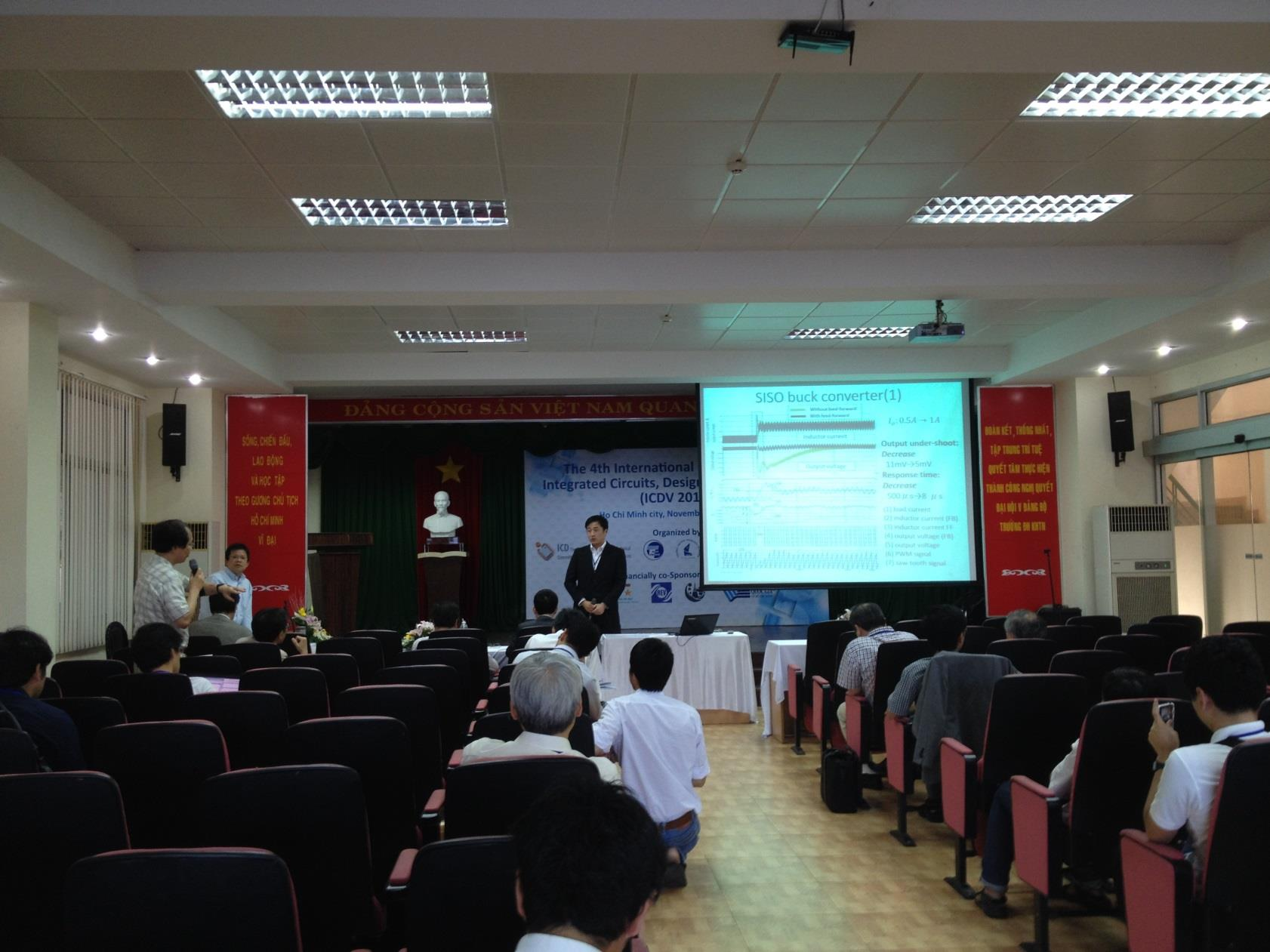
21 SISO buck converter(1) Without feed-forward With feed-forward Inductor current Output voltage I o : 0.5A 1A Output under-shoot: Decrease 11mV 5mV Response time: Decrease 500μ s 8 μ s (1) load current (2) inductor current (FB) (3) inductor current FF (4) output voltage (FB) (5) output voltage (6) PWM signal (7) saw-tooth signal 2013/11/16 21
 load current (2) inductor current (FB) (3) inductor current FF (4) output voltage (FB) (5) output voltage (6)")
22 SISO buck converter(2) Without feed-forward With feed-forward Inductor current I o : 0.5A 1.5A Output voltage (1) load current (2) inductor current (FB) (3) inductor current FF (4) output voltage (FB) (5) output voltage (6) PWM signal (7) saw-tooth signal 2013/11/16 22
")
23 SIDO buck converter(1) I o1 : 0.5A 0.96A, I o2 : 0.5A Without feed-forward With feed-forward 6V 4V Feed-forward With Without Self-regulation -- 25mV Cross-regulation -- 30mV (1) load current of sub-converter1 (2) load current of sub-converter2 2013/11/16 23

24 SIDO buck converter(2) I o1 : 0.5A, I o2 : 0.5A 1.85A Without feed-forward With feed-forward 6V 4V Feed-forward With Without Self-regulation 5mV 35mV Cross-regulation 10mV 40mV (1) load current of sub-converter1 (2) load current of sub-converter2 2013/11/16 24
25 Outline Research Objective Proposed Feed-forward Control Method Capacitor Charge Balance Proposed Feed-forward Controller Simulation Results SISO Buck Converter Simulation SIDO Buck Converter Simulation Conclusion 2013/11/16 25
26 Conclusion Proposed new feed-forward controller Simple: Only output capacitor current is detected Digital nonlinear calculation not required Applicable to SIDO converter Cost-effective Available: Transient response is Significantly improved Cross-regulation of SIDO converter is improved 2013/11/16 26
27 The End Thanks for your attention 2013/11/16 27
")
28 Presented by 呉澍 (Wu Shu) 2013/11/16 28
29 Q&A 2013/11/16 29
30 Question and Answer 1 The simulation result in page 21 and 22, there is oscillation in output voltage after transient response. Is it a right result? No, it is not a good result. This oscillation is caused by qualitatively multi-period integration compensation. But feed-forward require accurate control variable modulation. This problem will be improved in further.
31 Question and Answer 2 Normally when we talk about the voltage control mode and the current control mode of switching power supplies, they belong to feedback control scheme. What is the different between your proposed method and current control mode? Current control mode is feedback control. Inductor current is detected and compared with error signal. By this comparison, duty cycle is regulated. While our proposed method use capacitor current to regulate sawtooth signal. When transient response happen, we don t need wait until error signal is changed, then regulate duty cycle.
Designing Stable Compensation Networks for Single Phase Voltage Mode Buck Regulators
 Designing Stable Compensation Networks for Single Phase Voltage Mode Buck Regulators Technical Brief December 3 TB47. Author: Doug Mattingly Assumptions This Technical Brief makes the following assumptions:.
3-Phase Synchronous PWM Controller IC Provides an Integrated Solution for Intel VRM 9.0 Design Guidelines
 3-Phase Synchronous PWM Controller IC Provides an Integrated Solution for Intel VRM 9.0 Design Guidelines Odile Ronat International Rectifier The fundamental reason for the rapid change and growth in information
Application of network analyzer in measuring the performance functions of power supply
 J Indian Inst Sci, July Aug 2006, 86, 315 325 Indian Institute of Science Application of network analyzer in measuring the performance functions of power supply B SWAMINATHAN* AND V RAMANARAYANAN Power
Fundamentals of Power Electronics. Robert W. Erickson University of Colorado, Boulder
 Robert W. Erickson University of Colorado, Boulder 1 1.1. Introduction to power processing 1.2. Some applications of power electronics 1.3. Elements of power electronics Summary of the course 2 1.1 Introduction
Design A High Performance Buck or Boost Converter With Si9165
 Design A High Performance Buck or Boost Converter With Si9165 AN723 AN723 by Kin Shum INTRODUCTION The Si9165 is a controller IC designed for dc-to-dc conversion applications with 2.7- to 6- input voltage.
Switch Mode Power Supply Topologies
 Switch Mode Power Supply Topologies The Buck Converter 2008 Microchip Technology Incorporated. All Rights Reserved. WebSeminar Title Slide 1 Welcome to this Web seminar on Switch Mode Power Supply Topologies.
Lecture 24. Inductance and Switching Power Supplies (how your solar charger voltage converter works)
") Lecture 24 Inductance and Switching Power Supplies (how your solar charger voltage converter works) Copyright 2014 by Mark Horowitz 1 Roadmap: How Does This Work? 2 Processor Board 3 More Detailed Roadmap
Lecture 24 Inductance and Switching Power Supplies (how your solar charger voltage converter works) Copyright 2014 by Mark Horowitz 1 Roadmap: How Does This Work? 2 Processor Board 3 More Detailed Roadmap
AC/DC Power Supply Reference Design. Advanced SMPS Applications using the dspic DSC SMPS Family
 AC/DC Power Supply Reference Design Advanced SMPS Applications using the dspic DSC SMPS Family dspic30f SMPS Family Excellent for Digital Power Conversion Internal hi-res PWM Internal high speed ADC Internal
Power Electronic Circuits
 Power Electronic Circuits Assoc. Prof. Dr. H. İbrahim OKUMUŞ Karadeniz Technical University Engineering Faculty Department of Electrical And Electronics 1 DC to DC CONVERTER (CHOPPER) General Buck converter
Development of High Frequency Link Direct DC to AC Converters for Solid Oxide Fuel Cells (SOFC)
") Development of High Frequency Link Direct DC to AC Converters for Solid Oxide Fuel Cells (SOFC) Dr. Prasad Enjeti Power Electronics Laboratory Department of Electrical Engineering College Station, TX -
Development of High Frequency Link Direct DC to AC Converters for Solid Oxide Fuel Cells (SOFC) Dr. Prasad Enjeti Power Electronics Laboratory Department of Electrical Engineering College Station, TX -
Laboratory 4: Feedback and Compensation
 Laboratory 4: Feedback and Compensation To be performed during Week 9 (Oct. 20-24) and Week 10 (Oct. 27-31) Due Week 11 (Nov. 3-7) 1 Pre-Lab This Pre-Lab should be completed before attending your regular
Op Amp Circuit Collection
 Op Amp Circuit Collection Note: National Semiconductor recommends replacing 2N2920 and 2N3728 matched pairs with LM394 in all application circuits. Section 1 Basic Circuits Inverting Amplifier Difference
Understanding Power Impedance Supply for Optimum Decoupling
 Introduction Noise in power supplies is not only caused by the power supply itself, but also the load s interaction with the power supply (i.e. dynamic loads, switching, etc.). To lower load induced noise,
Lecture 24: Oscillators. Clapp Oscillator. VFO Startup
 Whites, EE 322 Lecture 24 Page 1 of 10 Lecture 24: Oscillators. Clapp Oscillator. VFO Startup Oscillators are circuits that produce periodic output voltages, such as sinusoids. They accomplish this feat
Parametric variation analysis of CUK converter for constant voltage applications
 ISSN (Print) : 232 3765 (An ISO 3297: 27 Certified Organization) Vol. 3, Issue 2, February 214 Parametric variation analysis of CUK converter for constant voltage applications Rheesabh Dwivedi 1, Vinay
Power supply output voltages are dropping with each
 DESIGNER S SERIES Second-Stage LC Filter Design First Inductor by Dr. Ray Ridley First Capacitor Power supply output voltages are dropping with each new generation of Integrated Circuits (ICs). Anticipated
Precision Diode Rectifiers
 by Kenneth A. Kuhn March 21, 2013 Precision half-wave rectifiers An operational amplifier can be used to linearize a non-linear function such as the transfer function of a semiconductor diode. The classic
MODELING AND SIMULATION OF A THREE-PHASE INVERTER WITH RECTIFIER-TYPE NONLINEAR LOADS
 , pp. 7-1 MODELING AND SIMULAION OF A HREE-PHASE INERER WIH RECIFIER-YPE NONLINEAR LOADS Jawad Faiz 1 and Ghazanfar Shahgholian 2 1 School of Electrical and Computer Engineering, Faculty of Engineering,
Testing a power supply for line and load transients
 Testing a power supply for line and load transients Power-supply specifications for line and load transients describe the response of a power supply to abrupt changes in line voltage and load current.
LM2576R. 3.0A, 52kHz, Step-Down Switching Regulator FEATURES. Applications DESCRIPTION TO-220 PKG TO-220V PKG TO-263 PKG ORDERING INFORMATION
 LM2576 FEATURES 3.3, 5.0, 12, 15, and Adjustable Output ersions Adjustable ersion Output oltage Range, 1.23 to 37 +/- 4% AG10Maximum Over Line and Load Conditions Guaranteed 3.0A Output Current Wide Input
Simple PWM Boost Converter with I/O Disconnect Solves Malfunctions Caused when V OUT <V IN
 Simple PWM Boost Converter with I/O Disconnect Solves Malfunctions Caused when V OUT
TDA4605 CONTROL CIRCUIT FOR SWITCH MODE POWER SUPPLIES USING MOS TRANSISTORS
 CONTROL CIRCUIT FOR SWITCH MODE POWER SUPPLIES USING MOS TRANSISTORS Fold-Back Characteristic provides Overload Protection for External Diodes Burst Operation under Short-Circuit and no Load Conditions
MP2365 3A, 28V, 1.4MHz Step-Down Converter
 The Future of Analog IC Technology MP365 3A, 8,.MHz Step-Down Converter DESCRIPTION The MP365 is a.mhz step-down regulator with a built-in Power MOSFET. It achieves 3A continuous output current over a
Single-Stage High Power Factor Flyback for LED Lighting
 Application Note Stockton Wu AN012 May 2014 Single-Stage High Power Factor Flyback for LED Lighting Abstract The application note illustrates how the single-stage high power factor flyback converter uses
MP2259 1A, 16V, 1.4MHz Step-Down Converter
 MP59 1A, 1V, 1.MHz Step-Down Converter TM The Future of Analog IC Technology DESCRIPTION The MP59 is a monolithic integrated stepdown switch mode converter with an internal power MOSFET. It achieves 1A
Application Note, Rev.1.0, September 2008 TLE8366. Application Information. Automotive Power
 Application Note, Rev.1.0, September 2008 TLE8366 Automotive Power Table of Contents 1 Abstract...3 2 Introduction...3 3 Dimensioning the Output and Input Filter...4 3.1 Theory...4 3.2 Output Filter Capacitor(s)
28V, 2A Buck Constant Current Switching Regulator for White LED
 28V, 2A Buck Constant Current Switching Regulator for White LED FP7102 General Description The FP7102 is a PWM control buck converter designed to provide a simple, high efficiency solution for driving
Technical Note #3. Error Amplifier Design and Applications. Introduction
 Technical Note #3 Error Amplifier Design and Applications Introduction All regulating power supplies require some sort of closed-loop control to force the output to match the desired value. Both digital
SWITCH-MODE POWER SUPPLY CONTROLLER PULSE OUTPUT DC OUTPUT GROUND EXTERNAL FUNCTION SIMULATION ZERO CROSSING INPUT CONTROL EXTERNAL FUNCTION
 SWITCH-MODE POWER SUPPLY CONTROLLER. LOW START-UP CURRENT. DIRECT CONTROL OF SWITCHING TRAN- SISTOR. COLLECTOR CURRENT PROPORTIONAL TO BASE-CURRENT INPUT REERSE-GOING LINEAR OERLOAD CHARACTERISTIC CURE
TDA2040. 20W Hi-Fi AUDIO POWER AMPLIFIER
 20W Hi-Fi AUDIO POWER AMPLIFIER DESCRIPTION The TDA2040 is a monolithic integrated circuit in Pentawatt package, intended for use as an audio class AB amplifier. Typically it provides 22W output power
Input and Output Capacitor Selection
 Application Report SLTA055 FEBRUARY 2006 Input and Output Capacitor Selection Jason Arrigo... PMP Plug-In Power ABSTRACT When designing with switching regulators, application requirements determine how
Introduction to SMPS Control Techniques
 Introduction to SMPS Control Techniques 2006 Microchip Technology Incorporated. All Rights Reserved. Introduction to SMPS Control Techniques Slide 1 Welcome to the Introduction to SMPS Control Techniques
Design of a TL431-Based Controller for a Flyback Converter
 Design of a TL431-Based Controller for a Flyback Converter Dr. John Schönberger Plexim GmbH Technoparkstrasse 1 8005 Zürich 1 Introduction The TL431 is a reference voltage source that is commonly used
Chapter 11 Current Programmed Control
 Chapter 11 Current Programmed Control Buck converter v g i s Q 1 D 1 L i L C v R The peak transistor current replaces the duty cycle as the converter control input. Measure switch current R f i s Clock
Bi-directional Power System for Laptop Computers
 Bi-directional Power System for Laptop Computers Terry L. Cleveland Staff Applications Engineer Microchip Technology Inc. [email protected] Abstract- Today the typical laptop computer uses
Interfacing Analog to Digital Data Converters
 Converters In most of the cases, the PIO 8255 is used for interfacing the analog to digital converters with microprocessor. We have already studied 8255 interfacing with 8086 as an I/O port, in previous
AP1509. 150KHz, 2A PWM BUCK DC/DC CONVERTER. Description. Pin Assignments V IN. Applications. Features. (Top View) GND GND. Output AP1509 GND GND
 GND GND. Output AP1509 GND GND") Description Pin Assignments The series are monolithic IC designed for a stepdown DC/DC converter, and own the ability of driving a 2A load without additional transistor. It saves board space. The external
Description Pin Assignments The series are monolithic IC designed for a stepdown DC/DC converter, and own the ability of driving a 2A load without additional transistor. It saves board space. The external
LM 358 Op Amp. If you have small signals and need a more useful reading we could amplify it using the op amp, this is commonly used in sensors.
 LM 358 Op Amp S k i l l L e v e l : I n t e r m e d i a t e OVERVIEW The LM 358 is a duel single supply operational amplifier. As it is a single supply it eliminates the need for a duel power supply, thus
Bridgeless PFC Implementation Using One Cycle Control Technique
 Bridgeless PFC Implementation Using One Cycle Control Technique Bing Lu Center for Power Electronics Systems Virginia Polytechnic Institute and State University 674 Whittemore Hall Blacksburg, VA 24061
1ED Compact A new high performance, cost efficient, high voltage gate driver IC family
 1ED Compact A new high performance, cost efficient, high voltage gate driver IC family Heiko Rettinger, Infineon Technologies AG, Am Campeon 1-12, 85579 Neubiberg, Germany, [email protected]
Design and Simulation of Soft Switched Converter Fed DC Servo Drive
 International Journal of Soft Computing and Engineering (IJSCE) ISSN: 2231-237, Volume-1, Issue-5, November 211 Design and Simulation of Soft Switched Converter Fed DC Servo Drive Bal Mukund Sharma, A.
Inrush Current. Although the concepts stated are universal, this application note was written specifically for Interpoint products.
 INTERPOINT Although the concepts stated are universal, this application note was written specifically for Interpoint products. In today s applications, high surge currents coming from the dc bus are a
TM MP2305 2A, 23V SYNCHRONOUS RECTIFIED, STEP-DOWN CONVERTER
 The Future of Analog IC Technology TM TM MP305 A, 3 Synchronous Rectified Step-Down Converter DESCRIPTION The MP305 is a monolithic synchronous buck regulator. The device integrates 30mΩ MOSFETS that provide
Power supplies. EE328 Power Electronics Assoc. Prof. Dr. Mutlu BOZTEPE Ege University, Dept. of E&E
 Power supplies EE328 Power Electronics Assoc. Prof. Dr. Mutlu BOZTEPE Ege University, Dept. of E&E EE328 POWER ELECTRONICS Outline of lecture Introduction to power supplies Modelling a power transformer
TDA2040. 20W Hi-Fi AUDIO POWER AMPLIFIER
 20W Hi-Fi AUDIO POWER AMPLIFIER DESCRIPTION The TDA2040 is a monolithic integrated circuit in Pentawatt package, intended for use as an audio class AB amplifier. Typically it provides 22W output power
A Simple Current-Sense Technique Eliminating a Sense Resistor
 INFINITY Application Note AN-7 A Simple Current-Sense Technique Eliminating a Sense Resistor Copyright 998 A SIMPE CURRENT-SENSE TECHNIQUE EIMINATING A SENSE RESISTOR INTRODUCTION A sense resistor R S,
Power Supplies. 1.0 Power Supply Basics. www.learnabout-electronics.org. Module
 Module 1 www.learnabout-electronics.org Power Supplies 1.0 Power Supply Basics What you ll learn in Module 1 Section 1.0 Power Supply Basics. Basic functions of a power supply. Safety aspects of working
Application Note 149. January 2015. Modeling and Loop Compensation Design of Switching Mode Power Supplies AN149-1. Henry J. Zhang
 Modeling and Loop Compensation Design of Switching Mode Power Supplies Henry J. Zhang January 25 Introduction Today s electronic systems are becoming more and more complex, with an increasing number of
Powering Integrated Circuits (ICs), and managing ripple voltage as it relates
, and managing ripple voltage as it relates") Ripple Voltage & ESR Powering Integrated Circuits (ICs), and managing ripple voltage as it relates to ESR of capacitors Low voltage ICs require supply voltage (Vcc) to have reduced levels of ripple voltage
Ripple Voltage & ESR Powering Integrated Circuits (ICs), and managing ripple voltage as it relates to ESR of capacitors Low voltage ICs require supply voltage (Vcc) to have reduced levels of ripple voltage
Considering the effects of UPS operation with leading power factor loads
 Considering the effects of UPS operation with leading power factor loads Over the past five years, a new generation of data processing and communications equipment has become prevalent in modern data centers
Technical Article. Multi-phase DC-DC PMIC: the efficient, space-saving choice for today s application processors. Peter Kammerlander
 Technical Multi-phase DC-DC PMIC: the efficient, space-saving choice for today s application processors Peter Kammerlander Multi-phase DC-DC PMIC: the efficient, space-saving choice for today s application
Tamura Closed Loop Hall Effect Current Sensors
 Tamura Closed Loop Hall Effect Current Sensors AC, DC, & Complex Currents Galvanic Isolation Fast Response Wide Frequency Bandwidth Quality & Reliability RoHs Compliance Closed Loop Hall Effect Sensors
OPERATIONAL AMPLIFIERS. o/p
 OPERATIONAL AMPLIFIERS 1. If the input to the circuit of figure is a sine wave the output will be i/p o/p a. A half wave rectified sine wave b. A fullwave rectified sine wave c. A triangular wave d. A
LM2704 Micropower Step-up DC/DC Converter with 550mA Peak Current Limit
 Micropower Step-up DC/DC Converter with 550mA Peak Current Limit General Description The LM2704 is a micropower step-up DC/DC in a small 5-lead SOT-23 package. A current limited, fixed off-time control
7-41 POWER FACTOR CORRECTION
 POWER FTOR CORRECTION INTRODUCTION Modern electronic equipment can create noise that will cause problems with other equipment on the same supply system. To reduce system disturbances it is therefore essential
ELECTRICAL ENGINEERING
 EE ELECTRICAL ENGINEERING See beginning of Section H for abbreviations, course numbers and coding. The * denotes labs which are held on alternate weeks. A minimum grade of C is required for all prerequisite
Harmonics and Noise in Photovoltaic (PV) Inverter and the Mitigation Strategies
 Inverter and the Mitigation Strategies") Soonwook Hong, Ph. D. Michael Zuercher Martinson Harmonics and Noise in Photovoltaic (PV) Inverter and the Mitigation Strategies 1. Introduction PV inverters use semiconductor devices to transform the
Soonwook Hong, Ph. D. Michael Zuercher Martinson Harmonics and Noise in Photovoltaic (PV) Inverter and the Mitigation Strategies 1. Introduction PV inverters use semiconductor devices to transform the
Programmable Single-/Dual-/Triple- Tone Gong SAE 800
 Programmable Single-/Dual-/Triple- Tone Gong Preliminary Data SAE 800 Bipolar IC Features Supply voltage range 2.8 V to 18 V Few external components (no electrolytic capacitor) 1 tone, 2 tones, 3 tones
100V - 100W DMOS AUDIO AMPLIFIER WITH MUTE/ST-BY THERMAL SHUTDOWN STBY-GND
 TDA7294 100V - 100W DMOS AUDIO AMPLIFIER WITH MUTE/ST-BY VERY HIGH OPERATING VOLTAGE RANGE (±40V) DMOS POWER STAGE HIGH OUTPUT POWER (UP TO 100W MU- SIC POWER) MUTING/STAND-BY FUNCTIONS NO SWITCH ON/OFF
Loop Stability Analysis Differential Opamp Simulation
 Department of Electrical and Computer Engineering Loop Stability Analysis Differential Opamp Simulation Vishal Saxena & Zhu Kehan Boise State University ([email protected]) Vishal Saxena -1-
POWER FORUM, BOLOGNA 20-09-2012
 POWER FORUM, BOLOGNA 20-09-2012 Convertitori DC/DC ad alta densità di potenza e bassa impedenza termica. Massimo GAVIOLI. Senior Field Application Engineer. Intersil SIMPLY SMARTER Challenges when Designing
Constant Current Control for DC-DC Converters
 Constant Current Control for DC-DC Converters Introduction... Theory of Operation... Power Limitations... Voltage Loop Stability...2 Current Loop Compensation...3 Current Control Example...5 Battery Charger
Dusk Dawn Detection & Battery. Discharge Management. Solar Panel and Battery Enable. Buck Boost Stage. Battery. Charge Circuit. User Set.
 Theory and Applications of the NCP294, Switching Controller, and Associated Circuits for Lead Acid Battery Charging from a Solar Panel with Maximum Peak Power Tracking (MPPT) APPLICATION NOTE Introduction
unit : mm With heat sink (see Pd Ta characteristics)
") Ordering number: EN1321E Monolithic Linear IC LA4261 3.5 W 2-Channel AF Power Amplifier for Home Stereos and Music Centers Features. Minimum number of external parts required (No input capacitor, bootstrap
Ordering number: EN1321E Monolithic Linear IC LA4261 3.5 W 2-Channel AF Power Amplifier for Home Stereos and Music Centers Features. Minimum number of external parts required (No input capacitor, bootstrap
EST7502B PC Power Supply PWM with Supervisor
 GENERAL DESCRIPTION The EST7502B is a pulse width modulation (PWM) control circuit with complete protection circuits for used in the SMPS (Switched Mode Power Supply). It contains various functions, which
Control of Boost type Converter in Discontinuous Conduction Mode by Controlling the Product of Inductor Voltage-Second
 Control of Boost type Converter in Discontinuous Conduction Mode by Controlling the Product of Inductor oltage-econd Chongming (Michael) Qiao, Jason Zhang International Rectifier 33 Kansas treet, El egundo,
Design of Four Input Buck-Boost DC-DC Converter for Renewable Energy Application
 Design of Four Input Buck-Boost DC-DC Converter for Renewable Energy Application A.Thiyagarajan Assistant Professor, Department of Electrical and Electronics Engineering Karpagam Institute of Technology
DC/DC BUCK Converter for Renewable Energy Applications Mr.C..Rajeshkumar M.E Power Electronic and Drives,
 DC/DC BUCK Converter for Renewable Energy Applications Mr.C..Rajeshkumar M.E Power Electronic and Drives, Mr.C.Anandaraj Assistant Professor -EEE Thiruvalluvar college of Engineering And technology, Ponnur
Contents. Preface. xiii. Part I 1
 Contents Preface xiii Part I 1 Chapter 1 Introduction to Frequency-Modulated Continuous-Wave 3 Radar 1.1 Brief History 3 1.2 Examples of Use of FMCW Radar 5 1.2.1 Radio Altimeters 5 1.2.2 Level-Measuring
Capacitor Ripple Current Improvements
 Capacitor Ripple Current Improvements The multiphase buck regulator topology allows a reduction in the size of the input and put capacitors versus single-phase designs. By quantifying the input and put
Evaluating AC Current Sensor Options for Power Delivery Systems
 Evaluating AC Current Sensor Options for Power Delivery Systems State-of-the-art isolated ac current sensors based on CMOS technology can increase efficiency, performance and reliability compared to legacy
Modeling and Analysis of DC Link Bus Capacitor and Inductor Heating Effect on AC Drives (Part I)
") 00-00-//$0.00 (c) IEEE IEEE Industry Application Society Annual Meeting New Orleans, Louisiana, October -, Modeling and Analysis of DC Link Bus Capacitor and Inductor Heating Effect on AC Drives (Part
00-00-//$0.00 (c) IEEE IEEE Industry Application Society Annual Meeting New Orleans, Louisiana, October -, Modeling and Analysis of DC Link Bus Capacitor and Inductor Heating Effect on AC Drives (Part
KA7500C. SMPS Controller. Features. Description. Internal Block Diagram. www.fairchildsemi.com
 SMPS Controller www.fairchildsemi.com Features Internal Regulator Provides a Stable 5V Reference Supply Trimmed to ±1% Accuracy. Uncommitted Output TR for 200mA Sink or Source Current Output Control for
UNDERSTANDING POWER FACTOR AND INPUT CURRENT HARMONICS IN SWITCHED MODE POWER SUPPLIES
 UNDERSTANDING POWER FACTOR AND INPUT CURRENT HARMONICS IN SWITCHED MODE POWER SUPPLIES WHITE PAPER: TW0062 36 Newburgh Road Hackettstown, NJ 07840 Feb 2009 Alan Gobbi About the Author Alan Gobbi Alan Gobbi
AND8280/D. NCP1351 Modeling Using the PWM Switch Technique APPLICATION NOTE
 NP5 Modeling Using the PWM Switch Technique Prepared by: Stéphanie onseil ON Semiconductor APPLIATION NOTE This document describes the average modeling of the NP5 a fixed on time / variable off time controller.
Current Ripple Factor of a Buck Converter
 Application Note Edwin Wang AN1 April 14 Current Ripple Factor of a Buck Converter Abstract Inductor and capacitor forms a low-pass filter in a buck converter. The corner frequency the C filter is always
MC13783 Buck and Boost Inductor Sizing
 Freescale Semiconductor Application Note Document Number: AN3294 Rev. 0.1, 01/2010 MC13783 Buck and Boost Inductor Sizing by: Power Management Application Team 1 Introduction The purpose of this application
MAS.836 HOW TO BIAS AN OP-AMP
 MAS.836 HOW TO BIAS AN OP-AMP Op-Amp Circuits: Bias, in an electronic circuit, describes the steady state operating characteristics with no signal being applied. In an op-amp circuit, the operating characteristic
Pulse Width Modulation (PWM) LED Dimmer Circuit. Using a 555 Timer Chip
 LED Dimmer Circuit. Using a 555 Timer Chip") Pulse Width Modulation (PWM) LED Dimmer Circuit Using a 555 Timer Chip Goals of Experiment Demonstrate the operation of a simple PWM circuit that can be used to adjust the intensity of a green LED by varying
Pulse Width Modulation (PWM) LED Dimmer Circuit Using a 555 Timer Chip Goals of Experiment Demonstrate the operation of a simple PWM circuit that can be used to adjust the intensity of a green LED by varying
Positive Feedback and Oscillators
 Physics 3330 Experiment #6 Fall 1999 Positive Feedback and Oscillators Purpose In this experiment we will study how spontaneous oscillations may be caused by positive feedback. You will construct an active
WHITE LED STEP-UP CONVERTER. Features
 General Description The is an inductor-based DC/DC converter designed to drive up to eight white LEDs in series for backlight. Only one feedback resistor is needed to control the LED current and obtain
AN ULTRA-CHEAP GRID CONNECTED INVERTER FOR SMALL SCALE GRID CONNECTION
 AN ULTRA-CHEAP GRID CONNECTED INVERTER FOR SMALL SCALE GRID CONNECTION Pramod Ghimire 1, Dr. Alan R. Wood 2 1 ME Candidate Email: [email protected] 2 Senior Lecturer: Canterbury University
Chapter 20 Quasi-Resonant Converters
 Chapter 0 Quasi-Resonant Converters Introduction 0.1 The zero-current-switching quasi-resonant switch cell 0.1.1 Waveforms of the half-wave ZCS quasi-resonant switch cell 0.1. The average terminal waveforms
User Guide #0602. User Guide for IRDC3624 Evaluation Board using IRF8910 SO-8, dual MOSFET and 2x 22µF ceramic output capacitors.
 User Guide #0602 User Guide for IRDC3624 Evaluation Board using IRF8910 SO-8, dual MOSFET and 2x 22µF ceramic output capacitors By Parviz Parto Table of Contents Page Description...1 Connections...1-2
Datasheet. 2A 380KHZ 20V PWM Buck DC/DC Converter. Features
 General Description Features The is a 380 KHz fixed frequency monolithic step down switch mode regulator with a built in internal Power MOSFET. It achieves 2A continuous output current over a wide input
CLASS-D VERTICAL DEFLECTION AMPLIFIER FOR TV AND MONITOR APPLICATION OUT CFLY + CFLY - BOOT VREG FEEDCAP FREQ. July 2001 1/8
 CLASS-D VERTICAL DEFLECTION AMPLIFIER FOR TV AND MONITOR APPLICATION FEATURES PRELIMINARY DATA HIGH EFFICIENCY POWER AMPLIFIER NO HEATSINK SPLIT SUPPLY INTERNAL FLYBACK GENERATOR OUTPUT CURRENT UP TO.5
3-Phase DC Brushless Motor Pre-Drivers Technical Information NJM2625A
 3Phase DC Brushless Motor PreDrivers 1.FEATURE NJM2625 is a controller and predriver for speed control 3phase blushless DC motor. The device provides the proper sequencing of 3phase drive output with external
UNISONIC TECHNOLOGIES CO., LTD
 UPS61 UNISONIC TECHNOLOGIES CO., LTD HIGH PERFORMANCE CURRENT MODE POWER SWITCH DESCRIPTION The UTC UPS61 is designed to provide several special enhancements to satisfy the needs, for example, Power-Saving
Output Filter Design for EMI Rejection of the AAT5101 Class D Audio Amplifier
 The AAT50 is a high efficiency, 2.5W mono class D audio power amplifier. It can be used in portable devices, such as MP4s, cell phones, laptops, GPS and PDAs. The device can work as a filterless class
Application Note SAW-Components
 Application Note SAW-Components Principles of SAWR-stabilized oscillators and transmitters. App: Note #1 This application note describes the physical principle of SAW-stabilized oscillator. Oscillator
Homework #11 203-1-1721 Physics 2 for Students of Mechanical Engineering
 Homework #11 203-1-1721 Physics 2 for Students of Mechanical Engineering 2. A circular coil has a 10.3 cm radius and consists of 34 closely wound turns of wire. An externally produced magnetic field of
Optimizing Power Efficiency in Point-of-Load Regulators Using SLLM (Simple Light Load Mode) Control. White Paper.
 Control. White Paper.") Innovations Embedded Optimizing Power Efficiency in Point-of-Load Regulators Using SLLM (Simple Light Load Mode) Control White Paper ROHM MarketingUSA Presented by ROHM Semiconductor Optimizing Power Efficiency
Innovations Embedded Optimizing Power Efficiency in Point-of-Load Regulators Using SLLM (Simple Light Load Mode) Control White Paper ROHM MarketingUSA Presented by ROHM Semiconductor Optimizing Power Efficiency
THE RIGHT-HALF-PLANE ZERO --A SIMPLIFIED EXPLANATION
 THE RGHT-HALF-PLANE ZERO --A SMPLFED EXPLANATON n small signal loop analysis, poles and zeros are normally located in the left half of the complex s-plane. The Bode plot of a conventional or lefthalf-plane
Welcome to this presentation on Switch Mode Drivers, part of OSRAM Opto Semiconductors LED Fundamentals series. In this presentation we will look at:
 Welcome to this presentation on Switch Mode Drivers, part of OSRAM Opto Semiconductors LED Fundamentals series. In this presentation we will look at: How switch mode drivers work, switch mode driver topologies,
MP2456 0.5A, 50V, 1.2MHz Step-Down Converter in a TSOT23-6
 MP2456 0.5A, 50V, 1.2MHz Step-Down Converter in a TSOT23-6 DESCRIPTION The MP2456 is a monolithic, step-down, switchmode converter with a built-in power MOSFET. It achieves a 0.5A peak-output current over
AP1506. 150KHz, 3A PWM BUCK DC/DC CONVERTER. Pin Assignments. Description. Features. Applications. ( Top View ) 5 SD 4 FB 3 Gnd 2 Output 1 V IN
 5 SD 4 FB 3 Gnd 2 Output 1 V IN") Description Pin Assignments The series are monolithic IC designed for a stepdown DC/DC converter, and own the ability of driving a 3A load without external transistor. Due to reducing the number of external
Description Pin Assignments The series are monolithic IC designed for a stepdown DC/DC converter, and own the ability of driving a 3A load without external transistor. Due to reducing the number of external
ENEE 307 Electronic Circuit Design Laboratory Spring 2012. A. Iliadis Electrical Engineering Department University of Maryland College Park MD 20742
 1.1. Differential Amplifiers ENEE 307 Electronic Circuit Design Laboratory Spring 2012 A. Iliadis Electrical Engineering Department University of Maryland College Park MD 20742 Differential Amplifiers
LM2575, NCV2575. http://onsemi.com. Features
 . A, Adjustable Voltage, Step-Down Switching Regulator The LM2575 series of regulators are monolithic integrated circuits ideally suited for easy and convenient design of a step down switching regulator
MIC33050. General Description. Features. Applications. Typical Application. 4MHz Internal Inductor PWM Buck Regulator with HyperLight Load
 4MHz Internal Inductor PWM Buck Regulator with HyperLight Load General Description The Micrel is a high-efficiency 600mA PWM synchronous buck (step-down) regulator with internal inductor featuring HyperLight