TRANSMISSION LINES. By Mike Kieffer, KD8OUT
|
|
|
- Natalie Lucas
- 9 years ago
- Views:
Transcription

1 TRANSMISSION LINES By Mike Kieffer, KD8OUT
2 I will be using ARRL Antenna Book 22 nd addition as my primary source material for this presentation. I also uses a series of articles by M. Walter Maxwell W2DU/W8HKK in QST from 4/73 to 8/76 titled: Another look at reflections. These articles are available for down load from ARRL site, under Transmission Lines.
 the")
3 A transceiver generates an AC (alternating current) signal that is delivers to a load or antenna to dissipate (transmit) the power.
4 Transmission lines in this presentation include all the connections from the transceiver to the energy emitting elements of the antenna. These elements form the transmission system. Because all modern transceivers are designed to work on a 50 ohm impedance, we must consider how impedance affects the design of an effective transmission system.
5 We need to review what is meant by Impedance Impedance is the AC analog to DC resistance. Remember E=IR For DC resistance? Impedance follows the same math, except we add a complex component, reactance. Z = R + j X ; we want 50 ohms Z= impedance, R= restive component, j= the complex operator, X= reactance The math gets ugly fast, hold on.

6 Impedance on the Cartesian system Where ω = 2* * F; X = reactance ohms, F=hertz, R = ohms, C = Farads, l = Henrys

7 Here is impedance in Polar coordinates: Where ω = 2* * F; X = reactance ohms, F=hertz, R = ohms, C = Farads, l = Henrys
8 Impedance calculates by: We must also understand the Decibel system of measuring power. The Decibel is a base 10 logarithmic system. The losses introduced in a transmission system are measured in db(decibel) lost. By using db, we can add each part of the transmission system s loss of power, to get the total loss and therefore how much useful power is delivered to the antenna.
9 db to power remaining: % Power left=10 / db lost Power Watts Watts left % OUT OUT 100w 600w % % % % % % % % % % % % % % % %
10 Common antenna impedances*: Loop horizontal (1λ) 100 ohms rising to 200 ohms at higher frequencies. Dipole - 72 to 74 ohms(1/2 λ) Vertical ohms (1/4 λ) Off center fed dipole 150 to 300 ohms Electrically short antennas are X (Capacitive) Electrically long antennas are +X (Inductive) Electrically equal antennas are 0X(Resonate) The antenna impedance varies with height off the ground, proximity to objects, configuration, operational frequency. *at resonance.
11 Feed lines have several important characteristics: Impedance Loss in db per 100 feet (matched line loss) Dielectric strength (short over voltage) Insulation type (Polyethylene, Teflon) Velocity factor Each type of transmission line has a characteristic velocity factor, which is a measure of how much slower the signal propagates through the transmission line, when compared to the ideal speed of light. So the electrical wave length, in a practical transmission line, is always shorter than the wave length in free space.
12 Common Feed lines
13 TRANSMISSION LINE MISSMATCH A transmission line is said to be mismatched if the lines characteristic impedance, the load s impedance and transceiver s impedance are different. The greater the mismatch, the more power is reflected back toward the source(your transceiver) and is re-reflected to the load. Most reflected power is re-reflected and eventually transmitted. More later.
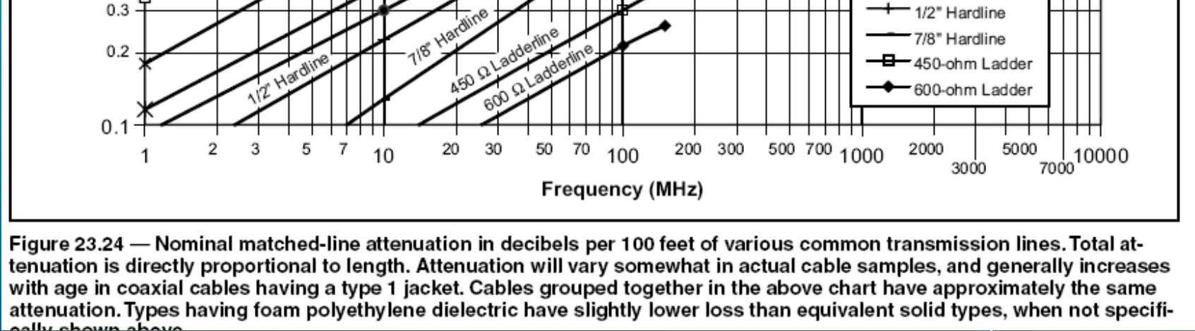
14 MATCHED LINE LOSS: The power lost (attenuated) in a perfectly matched line/load is called the matched line loss for the feed line and is usually given by the manufacturer as db loss/100 FEET and is frequency dependent. The higher the frequency for a given type of transmission line the greater the attenuation/100 feet.
15
16 What is Insertion Loss of connectors: There are 3 main causes of Insertion Loss: Reflected losses, Dielectric losses and Copper losses. Reflected losses are those losses caused by the VSWR of the connector. Dielectric losses are those losses caused by the power dissipated in the dielectric materials (Teflon, Rexolite, Delrin, etc.). Copper losses are those losses caused by the power dissipated due to the conducting surfaces of the connector. It is a function of the material and plating used. A typical 2$ Ampenol UHF connector is db attenuation at HF/VHF frequencies. 0.2 db for BNC connectors. Ampenol will not quote insertion loss or impedance for UHF connectors because they have too much variability and are not 50 Ω. An Ampenol Type N connector is specified at 50 Ω and insertion loss of 0.15 db up to 10 GHZ.

17 Typical connectors used by Hams: UHF BNC TYPE N
18 Insertion losses from devices: Every device you insert into the transmission line has an associated loss. These will be specified by the manufacturer in db, within a frequency range. Meters Lightning arrestors Matching units Baluns Matching transformers Connectors
19 Total losses in a transmission line is the sum of: Matched line attenuation Connector attenuation Device attenuation Additional loss due to SWR. Additional loss overlaid as a result of the other losses You can add up all these losses, in db and calculate how many watts are lost in the transmission of power from source to load.
20 SWR (standing wave ratio) and reflected power: It is a measure of the mismatch of a transmission system. Reflected power is the amount of power sent back from the load toward the source, re-reflected until eventually transmitted. Most reflected power is eventually transmitted, only the transmission line losses (attenuation of all kinds present) absorbs power and is wasted. The SWR (standing wave ratio) is: Pr = Power reverse, Pf = Power forward
21
22 It is a common misconception that minimum SWR occurs when the antenna is at resonance. By definition resonance is where the reactive component of impedance is 0, or purely resistive. Impedance = r + j0 This can be seen on a Smith Chart, because as the frequency changes, the impedance of the antenna changes. When the load is purely resistive, the antenna is said to be perfectly matched.
23 Additional loss of power due to SWR This is the loss beyond the matched line attenuation, and insertion attenuations. You take the line system attenuations in db and calculate the additional loss due to SWR and add them together for total transmission system loss. There are various calculators for determining the additional loss from SWR. At lower frequencies, even moderately high SWRs 10:1 or more, can generate small losses if the transmission system attenuations, that are use to determine the additional SWR loss, are small.
24 ADDITIONAL LOSS DUE TO SWR:
25 db to power remaining : % Power left=10 / db lost Power Watts Watts left % OUT OUT 100w 600w % % % % % % % % % % % % % % % %
26 Voltages in transmission line due to SWR: E(max) = P=Power watts, Z= Imp Ω Example: P=100w, Z0=50Ω, SWR=10: Emax = 223volts P=1000w, Z0=50, SWR=10: Emax = 707volts I(max) = E(max) / Z0 With a highly reactive load Z0 can get large and so does E(max). E(max) can easily reach 10,000volts and arc over coax.
27 The moral of the story is: SWR is not an indication of transmission line efficiency. If you have low transmission system losses, high SWRs can be tolerated, with a transmatch or utilizing a low matched loss transmission line. If you have high attenuation from line, connectors or devices, you need to tightly control SWR. Forward power minus reflected power IS NOT the net power radiated. Line system attenuation losses(matched, insertion, device and additional due to SWR) determine net power radiated or lost due to attenuation. Of course there are losses within the antenna itself, beyond transmission line losses, that affect real radiated power.
28 Antenna tuners(better named transmatch): A device between the source (rig) and the transmission line (typically) to present a 50 ohm load to the source match by conjugate matching. A tuner is typically coil(s) and capacitor(s) combination that cancels out the reactive component of the load(conjugate matching) and leaves a 50Ω resistive result. The tuner can be at the beginning or end of the feed line.
29 A commonly held misconception is that if I tune an antenna to a good SWR, I have low losses. No, a tuner cannot change the physics of the load system. All it is doing is matching the load impedance to the 50 ohm transceiver, keeping your rig happy and reflecting the SWR reflections back to the load. All the attenuation losses in transmission line system and antenna remain(such as ground losses) remain and dissipate power.
30 INCIDENT POWER: power after the matching unit, equals the source power plus the reflected power. Incident power is greater that source power whenever the SWR is greater than zero because of conservation of energy and wave mechanics. All power delivered to the load is absorbed or reflected back to the source and rereflected to the load. Only attenuation losses and additional loss due to SWR dissipate(waste) power in the transmission system.
31 WHERE IS THE BEST PLACE TO PUT YOUR TRANSMATCH(TUNER)?
32 EXAMPLE: In this example, the antenna is a 100 flat top, 50 over average ground. The dipole and is NOT resonate at either of the test frequencies. The antenna feed point impedance is: 3.8 mhz 39-j mhz 2493-j1375 As you can see, direct feeding the antenna with a 1:1 balun and 200 of RG-213 coax has losses 8.53 to 12.3 db. Using 300 ohm twin lead is better. Losses from 2.74 to 3.52 db Remote placement of the tuner is the best solution. Losses from 1.81 to 2.95 db. The ideal would be a tuner at the Y point of the antenna. This is possible on verticals, not so much on dipoles.

33 An example at 3.8 mhz (200 RG-213)

34 An example at 28.4 mhz (200 RG-213):
35 db to power remaining : % Power left=10 / db lost Power Watts Watts left % OUT OUT 100w 600w % % % % % % % % % % % % % % % %
36 COMMON MODE CURRENTS IN COAX CABLE Net current Bad current

37 How to get rid of common mode current: Purchase a current balun. It forces equal current in each antenna leg.
38 Wind a coax choke balun winding depend of frequency, any where from 6 to 40 feet of coax, longer for low bands, shorter for the high bands.

39 Add ferrite bead choke. Use Ω of impedance.
40 What is a balun: Balanced to unbalanced A dipole is a balanced load, coax is unbalanced, ladder line is balanced. A current balun forces equal current on both balanced legs and is used for impedance matching and stopping common mode currents. A voltage balun forces equal voltage on each balanced leg and is used for impedance matching. What is an unun Unbalanced to unbalanced A vertical is an unbalanced load. Feeding a vertical with coax can use an unun.
41 You can combine a transformer with a balun or unun: Say you want to feed your 50 ohm dipole with 450 ohm ladder line, you could use a 9:1 current balun. On the load side, many manual tuners have a built in balun to convert the balanced line back to coax. Remember antenna impedance varies with height, configuration and very much with frequency. With multiband antennas, the impedance matching ratio might be completely different.
42 Conclusions: Except in single band, resonant systems, your feed line is part of the bulk impedance your source sees. Changing the feed line in any way will change the impedance of the load system. If you are in doubt: Down load the ARRL TLW program. it is great to calculate complex feed line/antenna impedances. Use the best transmission line and connectors you can afford. Keep an eye on the losses from inserted devices.
 and this setup does not suffer from interference from near by objects, but the")
43 Conclusions: If you use coax, deal with common mode currents. Ladder lines do not have this problem. You can use two coax lines in parallel as a balanced feed line (tie shields together) and this setup does not suffer from interference from near by objects, but the line impedance is twice of each coax s characteristic impedance.
44 If you use ladder type lines, they cannot come near metal objects. They are best when there is a direct route from load to transmitter. Transmatches are helpful, but they do not eliminate inherent system attenuation(s) and should be placed as close to the load, if possible. This eliminates the overlay of SWR losses for the section of transmission line from source to the transmatch.
45 LAST: Don t worry about SWR to the exclusion of all other factors. SWR only affects transmission line loses as a multiplier of the underlying attenuations (matched, insertion and device). If those attenuations are low for your operating frequency, and you have a transmatch (that has enough range) to protect your source, SWR can be discounted.
Understanding SWR by Example
 Understanding SWR by Example Take the mystery and mystique out of standing wave ratio. Darrin Walraven, K5DVW It sometimes seems that one of the most mysterious creatures in the world of Amateur Radio
The Antenna Balun. What is this thing and why do I need it?
 What is this thing and why do I need it? The Antenna Balun In this chapter we will look at a common component in some transmission systems the balun. It is quite common to see a balun in wire antennas
Selecting Receiving Antennas for Radio Tracking
 Selecting Receiving Antennas for Radio Tracking Larry B Kuechle, Advanced Telemetry Systems, Inc. Isanti, Minnesota 55040 [email protected] The receiving antenna is an integral part of any radio location
Constructing a precision SWR meter and antenna analyzer. Mike Brink HNF, Design Technologist.
 Constructing a precision SWR meter and antenna analyzer. Mike Brink HNF, Design Technologist. Abstract. I have been asked to put together a detailed article on a SWR meter. In this article I will deal
Impedance Matching and Matching Networks. Valentin Todorow, December, 2009
 Impedance Matching and Matching Networks Valentin Todorow, December, 2009 RF for Plasma Processing - Definition of RF What is RF? The IEEE Standard Dictionary of Electrical and Electronics Terms defines
Just a Dipole. Gary Wescom N0GW July 16, 2007
 Just a Dipole Gary Wescom N0GW July 16, 2007 Often we will hear people describing their antennas as just a dipole. After all, a coax cable fed, half wavelength dipole is one of the simplest antennas to
LDG RBA-4:1Balun LDG RBA-1:1Balun
 LDG RBA-4:1Balun LDG RBA-1:1Balun Table of Contents Features 1 Specifications 1 Preparation 2 An important word about power levels: 2 Installation 2 Care and Maintenance 6 Technical Support 6 Warranty
40m-10m DELTA LOOP ANTENNA - GU3WHN
 This simple broad band antenna is easy to build, has gain similar to that of a dipole and is tolerant of nearby objects. It can be erected in almost any configuration provided the wires are well separated
The W5JCK Guide to the Mathematic Equations Required for the Amateur Extra Class Exam
 The W5JCK Guide to the Mathematic Equations Required for the Amateur Extra Class Exam This document contains every question from the Extra Class (Element 4) Question Pool* that requires one or more mathematical
Basic Wire Antennas. Part II: Loops and Verticals
 Basic Wire Antennas Part II: Loops and Verticals A loop antenna is composed of a single loop of wire, greater than a half wavelength long. The loop does not have to be any particular shape. RF power can
Antenna Deployment Technical Brief
 ProCurve Networking Antenna Deployment Technical Brief Introduction... 2 Antenna types... 2 Omni directional antennas... 2 Directional antennas... 2 Diversity antennas... 3 High gain directional antennas...
An equivalent circuit of a loop antenna.
 3.2.1. Circuit Modeling: Loop Impedance A loop antenna can be represented by a lumped circuit when its dimension is small with respect to a wavelength. In this representation, the circuit parameters (generally
Technician Licensing Class
 Technician Licensing Class Antennas Presented by Amateur Radio Technician Class Element 2 Course Presentation ELEMENT 2 SUB-ELEMENTS (Groupings) About Ham Radio Call Signs Control Mind the Rules Tech Frequencies
S-Parameters and Related Quantities Sam Wetterlin 10/20/09
 S-Parameters and Related Quantities Sam Wetterlin 10/20/09 Basic Concept of S-Parameters S-Parameters are a type of network parameter, based on the concept of scattering. The more familiar network parameters
Introduction to the Smith Chart for the MSA Sam Wetterlin 10/12/09 Z +
 Introduction to the Smith Chart for the MSA Sam Wetterlin 10/12/09 Quick Review of Reflection Coefficient The Smith chart is a method of graphing reflection coefficients and impedance, and is often useful
Digital Systems Ribbon Cables I CMPE 650. Ribbon Cables A ribbon cable is any cable having multiple conductors bound together in a flat, wide strip.
 Ribbon Cables A ribbon cable is any cable having multiple conductors bound together in a flat, wide strip. Each dielectric configuration has different high-frequency characteristics. All configurations
VE3MLB Phased Double V Antenna for 75/80 Meter Band
 Jan. 17, 2008 VE3MLB Phased Double V Antenna for 75/80 Meter Band This is a story of a double inverted V antenna that I built in January 2008. I already had a full 80 meter Delta loop suspended from my
My Loop Antenna. Stephen E. Sussman-Fort, Ph.D. AB2EW. [email protected]
 Stephen E. Sussman-Fort, Ph.D. AB2EW [email protected] Outline Brief History Characteristics of Small Loop Antennas for HF My Loop for 40m 15m Receive/Transmit Properties of Elect.-Small Loops Loop
Small HF Antennas - - -- - - - -- - - ! The Small Space and Big Antenna Dilemma! Constraints
 Small HF Antennas! The Small Space and Big Antenna Dilemma! Constraints " Covenants " Restricted lot size " City Bylaws " Boards of Variance " Strata Rules " Neighbor complaints of unsightly structures
Using Sim Smith to Improve Antenna Matching
 Using Sim Smith to Improve Antenna Matching Jim Brown K9YC [email protected] http://audiosystemsgroup.com/publish.htm The Objectives Eliminate antenna tuners Improve match to our rigs Minimize losses Improve
Applications in EMC testing. Outline. Antennas for EMC Testing. Terminology
 Antennas for EMC Testing Zhong Chen ETS-Lindgren 1301 Arrow Point Drive Cedar Park, TX 78613 [email protected] Outline EMC Terms and Definitions Typical EMC Antennas Calibration of EMC Antennas
Z-100 Automatic Antenna Tuner Manual Version 1.1
 Z-100 Automatic Antenna Tuner Manual Version 1.1 LDG Electronics 1445 Parran Road, PO Box 48 St. Leonard MD 20685-2903 USA Phone: 410-586-2177 Fax: 410-586-8475 [email protected] www.ldgelectronics.com
Marine HF SSB Installation and Grounding. Anatomy of the Best Tour 2006
 Marine HF SSB Installation and Grounding Anatomy of the Best Tour 2006 Marine HF Installation Considerations This document is meant to be an overview of Marine HF radio installation For detailed installation
RigExpert AA-30 Antenna Analyzer (0.1 to 30 MHz) AA-54 Antenna Analyzer (0.1 to 54 MHz) User s manual
 AA-54 Antenna Analyzer (0.1 to 54 MHz) User s manual") RigExpert AA-30 Antenna Analyzer (0.1 to 30 MHz) AA-54 Antenna Analyzer (0.1 to 54 MHz) User s manual Table of contents 1. Description... 3 2. Specifications... 4 3. Precautions... 5 4. Operation... 6
RigExpert AA-30 Antenna Analyzer (0.1 to 30 MHz) AA-54 Antenna Analyzer (0.1 to 54 MHz) User s manual Table of contents 1. Description... 3 2. Specifications... 4 3. Precautions... 5 4. Operation... 6
Critical thin-film processes such as deposition and etching take place in a vacuum
 WHITEPAPER INTRODUCING POWER SUPPLIES AND PLASMA Critical thin-film processes such as deposition and etching take place in a vacuum SYSTEMS chamber in the presence of a plasma. A plasma is an electrically
Antenna Basic Concepts
 ANTENNA An antenna is a device to transmit and/or receive electromagnetic waves. Electromagnetic waves are often referred to as radio waves. Most antennas are resonant devices, which operate efficiently
Chapter 7 Antenna measurements.
 Chapter 7 Antenna measurements. This is the reason I think the most HAM's have bought the VNWA. I must say, it is indeed a handy little device for this. But let I warn you. This takes a lot of the magic
BALUNS PART I. Andy Griffith W4ULD
 BALUNS PART I Andy Griffith W4ULD Recently I was thumbing through my files on baluns and realized that over the years I had collected a wealth of information that could be of use to fellow Hams. So, I
The VHF / UHF «Eggbeater» Antenna ~ Revisited ~
 The VHF / UHF «Eggbeater» Antenna ~ Revisited ~ ON6WG / F5VIF A new simple way to build the Eggbeater Antenna Introduction Previous designs described in «VHF / UHF «Eggbeater» Antenna ~ Part 1» and «VHF
Single Transistor FM Transmitter Design
 Single Transistor FM Transmitter Design In telecommunications, frequency modulation (FM) conveys information over a carrier wave by varying its frequency. FM is commonly used at VHF radio frequencies for
ZS6BKW vs G5RV. Antenna Patterns/SWR at 40 ft Center height, 27 ft end height ~148 Degree Included Angle
 ZS6BKW vs G5RV Antenna Patterns/SWR at 40 ft Center height, 27 ft end height ~148 Degree Included Angle Compiled By: Larry James LeBlanc 2010 For the AARA Ham Radio Club Note: All graphs computed using
Compact Integrated Antennas
 Freescale Semiconductor, Inc. Application Note Document Number: AN2731 Rev. 3, 09/2015 Compact Integrated Antennas Designs and Applications for the MC1321x, MC1322x, MC1323x, and MKW40/30/20 1 Introduction
Cellular Wireless Antennas
 Cellular Wireless Antennas A Technical Brief GarrettCom Inc., November 2010 Overview The Cellular Wireless Antenna Technical brief is provided to assist with the design and deployment of the DX940 Cellular
MAGNETICS: FERRITES, BEADS and BALUNS
 HF OPERATORS MAGNETICS: FERRITES, BEADS and BALUNS by John White VA7JW NSARC HF Operators 1 What s the Problem?! HF Dipoles and coaxial cables have a nasty compatibility problem! Dipoles are balanced structures!
Capacitor Self-Resonance
 Capacitor Self-Resonance By: Dr. Mike Blewett University of Surrey United Kingdom Objective This Experiment will demonstrate some of the limitations of capacitors when used in Radio Frequency circuits.
Coaxial Transmitting Chokes
 Coaxial Transmitting Chokes Jim Brown K9YC Santa Cruz, CA http://audiosystemsgroup.com Understanding Common Mode and Differential Mode Currents on Transmission Lines 1 Differential Mode Current Transmission
Weekend Antennas No. 1 A Bobtail Curtain for 2m
 Weekend Antennas No. 1 A Bobtail Curtain for 2m Welcome to the first installment of my new column, which I hope will become a regular feature in Radio ZS. Each installment will present a practical and
PLEASE - Read this entire booklet and study the diagrams before building a Quad, it can save you unwarranted frustrations!
 VHF/UHF Quad Antenna The information in this article has come from many amateur sources, the most notable was from WA6TEY (sk 1985) Ray Frost, who was a pioneer of VHF Quad designs and one of the best
Owners Manual For The PackTenna Mini
 Owners Manual For The PackTenna Mini By Nick Garner N3WG and George Zafiropoulos KJ6VU Quickstart With The 9:1 Random Wire Version You can identify this version because it has a yellow shrink wrap on the
This Antenna Basics reference guide includes basic information about antenna types, how antennas work, gain, and some installation examples.
 Antenna Basics This Antenna Basics reference guide includes basic information about antenna types, how antennas work, gain, and some installation examples. What Do Antennas Do? Antennas transmit radio
Standex-Meder Electronics. Custom Engineered Solutions for Tomorrow
 Standex-Meder Electronics Custom Engineered Solutions for Tomorrow RF Reed Relays Part II Product Training Copyright 2013 Standex-Meder Electronics. All rights reserved. Introduction Purpose Designing
Shielding Effectiveness Test Method. Harbour s LL, SB, and SS Coaxial Cables. Designs for Improved Shielding Effectiveness
 Shielding Effectiveness Test Method Harbour s LL, SB, and SS Coaxial Cables Designs for Improved Shielding Effectiveness Harbour Industries 4744 Shelburne Road Shelburne Vermont 05482 USA 802-985-3311
Dummies guide to aircraft antennas
 Dummies guide to aircraft antennas Probably the single biggest issue that we encounter with the installation of our XCOM radios by customers in the field is poor antenna performance. Most customers are
The Gamma Match. 1 Equal Size Elements
 The Gamma Match The gamma match was originally invented as a means of feeding vertical monopole antennas for medium wave broadcasts, which were earthed at the base for lightning protection (see Figure
RLC Resonant Circuits
 C esonant Circuits Andrew McHutchon April 20, 203 Capacitors and Inductors There is a lot of inconsistency when it comes to dealing with reactances of complex components. The format followed in this document
End Fed Antenna. Operating Manual. version 1.1
 Cross Country Wireless (2009) Ltd, 7 Thirlmere Grove, BOLTON, BL4 0QB, UK Email [email protected] Web page http://www.crosscountrywireless.net Telephone +44 (0) 1204 410626 Mobile GSM 900
A Tutorial on the Decibel
 A Tutorial on the Decibel This tutorial combines information from several authors, including Bob DeVarney, W1ICW; Walter Bahnzaf, WB1ANE; and Ward Silver, NØAX Decibels are part of many questions in the
HF OPERATORS SMALL HF ANTENNAS - - - - - - - - - - - Rev 1. John White VA7JW
 HF OPERATORS SMALL HF ANTENNAS Rev 1 by John White VA7JW NSARC HF Operators 1 Antenna Problems Big or Small always problems. Affects all - Single family, apartments, condo s, high rises, etc The Small
Impedance Matching. Using transformers Using matching networks
 Impedance Matching The plasma industry uses process power over a wide range of frequencies: from DC to several gigahertz. A variety of methods are used to couple the process power into the plasma load,
Avaya WLAN 9100 External Antennas for use with the WAO-9122 Access Point
 Avaya WLAN 9100 External Antennas for use with the WAO-9122 Access Point Overview To optimize the overall performance of a WLAN in an outdoor deployment it is important to understand how to maximize coverage
Line Reactors and AC Drives
 Line Reactors and AC Drives Rockwell Automation Mequon Wisconsin Quite often, line and load reactors are installed on AC drives without a solid understanding of why or what the positive and negative consequences
Connecting Your Receiver to the Antenna
 TECHNOTE No. 3 Joe Carr's Radio Tech-Notes Connecting Your Receiver to the Antenna Joseph J. Carr Universal Radio, Inc. 6830 Americana Parkway Reynoldsburg, Ohio 43068 1 Connecting Your Receiver to the
Cheap Antennas for the AMSAT LEO's Kent Britain -- WA5VJB
 Cheap Antennas for the AMSAT LEO's Kent Britain -- WA5VJB Cheap LEO Antenna Drew, KO4MA, using the Cheap LEO antenna during a Dayton AMSAT LEO Demonstration Hand held dual band antennas are popular for
Nexus Technology Review -- Exhibit A
 Nexus Technology Review -- Exhibit A Background A. Types of DSL Lines DSL comes in many flavors: ADSL, ADSL2, ADSL2+, VDSL and VDSL2. Each DSL variant respectively operates up a higher frequency level.
MEASUREMENT SET-UP FOR TRAPS
 Completed on 26th of June, 2012 MEASUREMENT SET-UP FOR TRAPS AUTHOR: IW2FND Attolini Lucio Via XXV Aprile, 52/B 26037 San Giovanni in Croce (CR) - Italy [email protected] Trappole_01_EN 1 1 DESCRIPTION...3
FILTERS - IN RADIO COMMUNICATIONS
 Reading 32 Ron Bertrand VK2DQ http://www.radioelectronicschool.com FILTERS - IN RADIO COMMUNICATIONS RADIO SIGNALS In radio communications we talk a lot about radio signals. A radio signal is a very broad
THE KW107 SUPERMATCH ATU manual, courtesy of Barry G0DWZ
 THE KW107 SUPERMATCH ATU manual, courtesy of Barry G0DWZ I ve copied the following directly from the KW107 manual without alteration. To clear up one or two ambiguous points, I have added my own comments
Selecting a Transmission Line for Your Broadcast System
 Selecting a Transmission Line for Your Broadcast System Introduction This Bulletin presents the procedures broadcasters need for calculating attenuation and power handling parameters to properly design
Antenna Trainer EAN. www.edibon.com. Technical Teaching Equipment INTRODUCTION
 Antenna Trainer EAN Technical Teaching Equipment Products Products range Units 3.-Communications INTRODUCTION Antennas are the main element of aerial communications. They are the transition between a transmission
ISS Minimalist Antenna
 ISS Minimalist Antenna The purpose of this project was to develop an antenna suggestion that would allow for a simple to duplicate, affordable antenna solution for reasonable access to signals transmitted
'' EGGBEATER '' ANTENNA VHF/UHF ~ PART 2
 '' EGGBEATER '' ANTENNA VHF/UHF ~ PART 2 ON6WG / F5VIF Summary Note : In Part 1, Fig 1 shows a maximum gain of 6.45 dbi. Several design attempts were made using slightly different configurations ( i.e.
Antenna Properties and their impact on Wireless System Performance. Dr. Steven R. Best. Cushcraft Corporation 48 Perimeter Road Manchester, NH 03013
 Antenna Properties and their impact on Wireless System Performance Dr. Steven R. Best Cushcraft Corporation 48 Perimeter Road Manchester, NH 03013 Phone (603) 627-7877 FAX: (603) 627-1764 Email: [email protected]
EMC STANDARDS STANDARDS AND STANDARD MAKING BODIES. International. International Electrotechnical Commission (IEC) http://www.iec.
 http://www.iec.") EMC STANDARDS The EMC standards that a particular electronic product must meet depend on the product application (commercial or military) and the country in which the product is to be used. These EMC regulatory
EMC STANDARDS The EMC standards that a particular electronic product must meet depend on the product application (commercial or military) and the country in which the product is to be used. These EMC regulatory
Siemens Energy & Automation. structured. WIRING Product Training Series: Advanced Video Session 3
 s structured WIRING Product Training Series: Advanced Video Session 3 1 Table of Contents This presentation will give you a closer look at Video in Structured Wiring applications. The following Areas will
Byonics Micro Trak 1000 High Altitude Balloon Tracker
 Byonics Micro Trak 1000 High Altitude Balloon Tracker The Micro Trak 1000 (MT 1000) is a high altitude balloon (HAB) tracker. It is usually sold as a combination to provide a simple, turn key tracking
On Cables and Connections A discussion by Dr. J. Kramer
 KRAMER ELECTRONICS LTD. On Cables and Connections A discussion by Dr. J. Kramer We are frequently asked - "what length of cable can I use for a specific application?" Seemingly a simple question, but the
2 Meter Half-Wave J-Pole Antenna From 450 Ohm Ladder Line
 2 Meter Half-Wave J-Pole Antenna From 450 Ohm Ladder Line Photos: Copyright 2007 David Jordan WA3GIN. All rights reserved. This is a good rainy day antenna project for those of you who would like to home
BASIC ELECTRONICS AC CIRCUIT ANALYSIS. December 2011
 AM 5-202 BASIC ELECTRONICS AC CIRCUIT ANALYSIS December 2011 DISTRIBUTION RESTRICTION: Approved for Pubic Release. Distribution is unlimited. DEPARTMENT OF THE ARMY MILITARY AUXILIARY RADIO SYSTEM FORT
Phase II Design for a Multiband LMR Antenna System
 Phase II Design for a Multiband LMR Antenna System S. Ellingson and R. Tillman Aug 30, 2011 Contents 1 Introduction 2 2 System Design 2 3 Antenna Tuner 3 Bradley Dept. of Electrical & Computer Engineering,
Modeling an 80/40/20M Fan Dipole for DX
 Modeling an 80/40/20M Fan Dipole for DX New Station New Antennas! Installation and SWR Response Where is the DX? How do these Dipoles Play? (EZNEC) What about Terrain? HFTA and Terrain The effect on these
Designing Log Periodic Antennas
 Designing Log Periodic Antennas By Glen Dash, Ampyx LLC, GlenDash at alum.mit.edu Copyright 2000, 2005 Ampyx LLC Lightweight and precise, the log periodic has become a favorite among EMC engineers. In
DL-QRP-AG Lambda/2 no Counterpoise: Fuchs Antenna matching unit
 DL-QRP-AG Lambda/2 no Counterpoise: Fuchs Antenna matching unit QRPproject Molchstr. 15 12524 Berlin http://www.qrpproject.de Telefon: +49(30) 85 96 13 23 e-mail: [email protected] Handbucherstellung:
APPLICATION NOTES POWER DIVIDERS. Things to consider
 Internet Copy Rev A Overview Various RF applications require power to be distributed among various paths. The simplest way this can be done is by using a power splitter/divider. Power dividers are reciprocal
Flexible PCB Antenna with Cable Integration Application Note Version 2
 Flexible PCB Antenna with Cable Integration Application Note Version 2 CONTENTS 1. BASICS 2. APPLICATIONS 3. SIZE 4. SHAPE 5. GROUND PLANE SIZE 6. IMPEDANCE 7. BANDWIDTH 8. VSWR 9. GAIN 10. EFFICIENCY
This paper will explain some of the more important factors on how UTP wires work; specifically it will cover the following:
 UTP Technology In the late 1970s, unshielded twisted pair (UTP) cabling originated in the computer industry as a means of transmitting digital data over computer networks. This cable was designed to be
Digital Active Indoor Antenna SRT ANT 10 ECO
 Digital Active Indoor Antenna SRT ANT 10 ECO Picture similar User Manual Table of contents 1.0 INTRODUCTION 1 2.0 PACKAGE CONTENT 1 3.0 SAFETY NOTES 2 4.0 CONNECTING THE ANTENNA 2 1.0 INTRODUCTION Thank
Antennas 101 The Basics. Ward Silver NØAX
 Antennas 101 The Basics Ward Silver NØAX The Basics - 1 Antennas radiate (or receive) because electrons are accelerated (or are caused to accelerate) in the antenna s elements Radio or electromagnetic
Since any real component also has loss due to the resistive component, the average power dissipated is 2 2R
 Quality factor, Q Reactive components such as capacitors and inductors are often described with a figure of merit called Q. While it can be defined in many ways, it s most fundamental description is: Q
Broadband Slotted Coaxial Broadcast Antenna Technology
 Broadband Slotted Coaxial Broadcast Antenna Technology Summary Slotted coaxial antennas have many advantages over traditional broadband panel antennas including much smaller size and wind load, higher
Product Name Hexa-Band Cellular SMD Antenna GSM / CDMA / DCS / PCS / WCDMA /UMTS /HSDPA / GPRS / EDGE 800 MHz to 2200 MHz
 Anam PA.25a Specification Part No. PA.25a Product Name Anam Hexa-Band Cellular SMD Antenna GSM / CDMA / DCS / PCS / WCDMA /UMTS /HSDPA / GPRS / EDGE 800 MHz to 2200 MHz Feature High Efficiency Multi-Band
EDEXCEL NATIONAL CERTIFICATE/DIPLOMA UNIT 5 - ELECTRICAL AND ELECTRONIC PRINCIPLES NQF LEVEL 3 OUTCOME 4 - ALTERNATING CURRENT
 EDEXCEL NATIONAL CERTIFICATE/DIPLOMA UNIT 5 - ELECTRICAL AND ELECTRONIC PRINCIPLES NQF LEVEL 3 OUTCOME 4 - ALTERNATING CURRENT 4 Understand single-phase alternating current (ac) theory Single phase AC
Measuring RF Parameters of Networks Bill Leonard NØCU
 Measuring RF Parameters of Networks Bill Leonard NØCU NAØTC - 285 TechConnect Radio Club http://www.naøtc.org/ What is a Network? A Network is a group of electrical components connected is a specific way
Coaxial Cable Feeder Influence on Yagi Antenna Dragoslav Dobričić, YU1AW [email protected]
 Coaxial Cable Feeder Influence on Yagi Antenna Dragoslav Dobričić, YU1AW [email protected] Introduction o far, in several previous articles [1, 2, 3], we investigated how boom radius and its S distance
Keysight Technologies Understanding the Fundamental Principles of Vector Network Analysis. Application Note
 Keysight Technologies Understanding the Fundamental Principles of Vector Network Analysis Application Note Introduction Network analysis is the process by which designers and manufacturers measure the
Current Probes, More Useful Than You Think
 Current Probes, More Useful Than You Think Training and design help in most areas of Electrical Engineering Copyright 1998 Institute of Electrical and Electronics Engineers. Reprinted from the IEEE 1998
LDG Z-100Plus 100-Watt Automatic Tuner
 Z-100PLUS OPERATIONS MANUAL MANUAL REV A LDG Z-100Plus 100-Watt Automatic Tuner LDG Electronics 1445 Parran Road St. Leonard MD 20685-2903 USA Phone: 410-586-2177 Fax: 410-586-8475 [email protected]
Common Mode and Differential Mode Noise Filtering
 Summary Introduction This application note gives a practical explanation of differential mode and common mode noise along with the traditional filtering approaches. In addition, an alternative method of
SIGNAL GENERATORS and OSCILLOSCOPE CALIBRATION
 1 SIGNAL GENERATORS and OSCILLOSCOPE CALIBRATION By Lannes S. Purnell FLUKE CORPORATION 2 This paper shows how standard signal generators can be used as leveled sine wave sources for calibrating oscilloscopes.
Measurement of Capacitance
 Measurement of Capacitance Pre-Lab Questions Page Name: Class: Roster Number: Instructor:. A capacitor is used to store. 2. What is the SI unit for capacitance? 3. A capacitor basically consists of two
THE OCF FD4 (FD3) WINDOM ANTENNA
 WINDOM ANTENNA") THE OCF FD4 (FD3) WINDOM ANTENNA FD4 (80/40/20/10 m) The 4-band Fritzel model FD4 is a special version of a Windom antenna. It is a half-wave long on the lowest frequency, and is fed from a coax cable
THE OCF FD4 (FD3) WINDOM ANTENNA FD4 (80/40/20/10 m) The 4-band Fritzel model FD4 is a special version of a Windom antenna. It is a half-wave long on the lowest frequency, and is fed from a coax cable
EE302 Lesson 14: Antennas
 EE302 Lesson 14: Antennas Loaded antennas /4 antennas are desirable because their impedance is purely resistive. At low frequencies, full /4 antennas are sometime impractical (especially in mobile applications).
CCTV System Troubleshooting Guide
 Wouldn t be nice to start and finish a CCTV System Project without running into any problems before, during and after the installation is completed. Well, in this article we will try and explain why we
LVDS Technology Solves Typical EMI Problems Associated with Cell Phone Cameras and Displays
 AN-5059 Fairchild Semiconductor Application Note May 2005 Revised May 2005 LVDS Technology Solves Typical EMI Problems Associated with Cell Phone Cameras and Displays Differential technologies such as
Design and Certification of ASH Radio Systems for Japan
 Design and Certification of ASH Radio Systems for Japan RFM s second-generation ASH radio hybrids are being used in a wide variety of applications in Japan, operating under the Japanese BIJAKU radio regulations.
AVX EMI SOLUTIONS Ron Demcko, Fellow of AVX Corporation Chris Mello, Principal Engineer, AVX Corporation Brian Ward, Business Manager, AVX Corporation
 AVX EMI SOLUTIONS Ron Demcko, Fellow of AVX Corporation Chris Mello, Principal Engineer, AVX Corporation Brian Ward, Business Manager, AVX Corporation Abstract EMC compatibility is becoming a key design
LDG DTS-4/4R Desktop Coaxial Switch / Remote
 LDG DTS-4/4R Desktop Coaxial Switch / Remote LDG Electronics 1445 Parran Road, PO Box 48 St. Leonard MD 20685-2903 USA Phone: 410-586-2177 Fax: 410-586-8475 [email protected] www.ldgelectronics.com
LDG YT-847 100-Watt Automatic Tuner for Yaesu FT-847 Transceivers
 YT-847 OPERATIONS MANUAL MANUAL REV A LDG YT-847 100-Watt Automatic Tuner for Yaesu FT-847 Transceivers LDG Electronics 1445 Parran Road St. Leonard MD 20685-2903 USA Phone: 410-586-2177 Fax: 410-586-8475
Amplifier for Small Magnetic and Electric Wideband Receiving Antennas (model AAA-1B)
") Amplifier for Small Magnetic and Electric Wideband Receiving Antennas (model AAA-1B) 1. Description and Specifications Contents 1.1 Description 1.2 1.2 Specifications 1.3 1.3 Tested parameters in production
Amplifier for Small Magnetic and Electric Wideband Receiving Antennas (model AAA-1B) 1. Description and Specifications Contents 1.1 Description 1.2 1.2 Specifications 1.3 1.3 Tested parameters in production
impedance is easier for the tuner to cope with across multiple bands which are related to even harmonic lengths of the dipole.
 By Ron Bertrand VK2DQ - 2007 Want to build a simple, efficient, multiband antenna? One of the best and inexpensive multiband antennas is the off-centre-fed (OCF) dipole. These are wonderfully simple antennas
TIMING SIGNALS, IRIG-B AND PULSES
 TIMING SIGNALS, IRIG-B AND PULSES Document No. PD0043200B July 2013 Arbiter Systems, Inc. 1324 Vendels Circle, Suite 121 Paso Robles, CA 93446 U.S.A. (805) 237-3831, (800) 321-3831 http://www.arbiter.com