7100 Series Fire Alarm Control Installation/Operating Manual. Document: Print Date: 6/6/07 Rev. I P/N Rev.
|
|
|
- Alexia Butler
- 8 years ago
- Views:
Transcription
1 7100 Series Fire Alarm Control Installation/Operating Manual Document: Print Date: 6/6/07 Rev. I P/N ECN: Copyright 1998 Honeywell International Inc. All Rights Reserved Published in U.S.A. 12 Clintonville Road, Northford, CT USA TEL: (203) FAX: (203)

2 Fire Alarm System Limitations While a fire alarm system may lower insurance rates, it is not a substitute for fire insurance! This manual is designed for use by factorytrained installers and operators of the Gamewell- FCI, 7100 Series, Fire Alarm Control. All illustrations, functional descriptions, operating and installation procedures, and other relevant information are contained in this manual. The contents of this manual are important, and the manual must be kept with the fire alarm control panel at all times. If building ownership is changed, this manual, including any testing and maintenance information, must be passed along to the new owner(s). The fire alarm control panel is part of a system. Manuals and instructions for other devices forming part of the system should be kept together. Purchasers who install this system for use by others must leave the instructions with the user. A copy of these instructions is included with each product and is available from the manufacturer. This equipment is Listed by various listing agencies for use in fire alarm systems. Use only components which are compatible with the Gamewell-FCI System. The installation MUST be in accordance with the instructions in this manual. THEREFORE: DO NOT deviate from the procedures described in this manual. DO NOT assume any details not shown in the instructions. DO NOT modify any electrical or mechanical features. DO comply with all codes and standards set forth by the Authority Having Jurisdiction. The term Authority Having Jurisdiction has become a standard term in the fire alarm industry. An acceptable definition of Authority Having Jurisdiction is: Fire alarm systems installed in the USA fall under the jurisdiction of some authority. In some areas this may be a local fire department; in other areas it may be a building inspector, insurance firm, etc. Different authorities may have their own local requirements for the way the fire alarm system is installed and used. Most local authorities base their requirements on the National Fire Protection Agency (NFPA) codes, but there may be important differences. You must install this system in the way in which the Authority Having Jurisdiction requires. If you do not know which authority has jurisdiction in your area, contact your local fire department or building inspector for guidance. It is important that you tell users to be aware of any requirements defined by the Authority Having Jurisdiction. E3 Series is a trademark of Honeywell International Inc. i The installation MUST be in accordance with the following standards: National Fire Alarm Code (NFPA 72) National Electrical Code (NFPA 70) Life Safety Code (NFPA 101) NFPA 92A Recommended Practice for Smoke Control Systems WARNING: Touching components which are improperly installed, applied or operated could be hazardous and possibly fatal. Short circuits could cause arcing that could result in molten metal injuries. Therefore, only qualified technicians familiar with electrical hazards should perform checkout procedures. Safety glasses should be worn, and test equipment used for voltage measurements should be designed for this purpose and be in good working order. ENVIRONMENTAL CONSIDERATIONS: It is important that this equipment be operated within its specifications: Recommended operating 60 to 80 F temperature range: (15 to 27 C) Absolute maximum 32 to 120 F operating temperature (0 to 49 C) range: Operating humidity: Not to exceed 93% Non-condensing at 90 F (32 C) Operating this equipment within the recommended temperature range will extend the useful life of the system standby batteries. INSTALLATION CONSIDERATIONS: Check that you have all of the equipment you need to make the installation. Follow the field wiring diagrams and installation notes in this manual. Install the equipment in a clean, dry environment (minimal dust). Avoid installing equipment where vibrations will occur. Remove all electronic assemblies prior to drilling, filing, reaming, or punching the enclosure. When possible, make all cable entries from the sides; being careful to separate the power-limited conductors from the non power-limited conductors. Before making modifications, verify that they will not interfere with battery, transformer and printed circuit board location. Do not over-tighten screw terminals. Overtightening may damage threads, resulting in

3 reduced terminal contact pressure and difficulty with screw terminal removal. Disconnect all sources of power before servicing, removing, or inserting any circuit boards. Control unit and associated equipment may be damaged by removing and/or inserting cards, sub-assemblies, or interconnecting cables while the unit is energized. WIRING CONSIDERATIONS: This fire alarm control panel contains powerlimited circuits. You cannot connect external sources of power to these circuits without invalidating their approval. Verify that wire sizes are adequate for all initiating device and notification appliance circuits. Most devices cannot tolerate more than a 10% drop from the specified device voltage. The installer must make sure that the wiring and devices installed in the system meet the current National Electrical Code, NFPA 70, and all applicable state and local building code requirements. Use the conductor size and type required by local codes. (See NFPA 70, Article 760). Wiring resistance must not be more than that shown on the field wiring diagrams. To reduce errors and help in servicing the system, all conductors should be tagged or otherwise coded and logged at installation to identify circuit assignment and polarity. If the conductors are logged with a code, keep the log that explains the code with the manual, so that it is available to other people working on the panel. Like all solid state electronic devices, this system may operate erratically or be damaged when subjected to lightening induced transients. Although no system is completely immune to lightening transients and interference, proper grounding will reduce susceptibility. We do not recommend the use of overhead or outside aerial wiring due to the increased susceptibility to nearby lightening strikes. Consult with the Gamewell-FCI Technical Support Department if any problems are anticipated or encountered. To prevent the spread of fire, use proper patching materials to areas where system wiring passes through the fire-rated walls or floors. SURVIVABILITY: Per the National Fire Alarm Code, NFPA 72, all circuits necessary for the operation of the notification appliances shall be protected until they enter the evacuation signaling zone that they serve. Any of the following methods shall be considered acceptable as meeting these requirements: 1) A 2-hour rated cable or cable system 2) A 2-hour rated enclosure 3) Performance alternatives approved by Authority Having Jurisdiction MAINTENANCE: To keep your fire alarm system in excellent working order, ongoing maintenance is required per the manufacturer s recommendations and UL and NFPA Standards, and applicable state and local codes. At a minimum, the requirements of Chapter 7 of NFPA, the National Fire Alarm Code, shall be followed. A preventative maintenance agreement should be arranged through the manufacturer s local representative. Though smoke detectors are designed for long life, they may fail at any time. Any smoke detector, fire alarm system, or any component of that system shall be repaired or replaced immediately. OTHER CONSIDERATIONS: The equipment was tested according to EC directive 89/336/EEC for Class A equipment and was verified to the limits and methods of EN An automatic fire alarm system typically made up of smoke detectors, heat detectors, manual pull stations, audible warning devices, and a fire alarm control panel with remote notification capability can provide early warning of a developing fire. Such a system, however, does not assure protection against property damage or loss of life resulting from a fire. The Manufacturer recommends that smoke and/or heat detectors be located throughout a protected premise following the recommendations of the current edition of the National Fire Protection Association NFPA Standard 72, manufacturer s recommendations, State and local codes. A study by the Federal Emergency Management Agency (an agency of the United States government) indicated that smoke detectors may not into alarm in as many as 35% of all fires. While fire alarm systems are designed to provide early warning against fire, they do not guarantee warning or protection against fire. A fire alarm system may not provide timely or adequate warning, or simply may not function, for a variety of reasons: Smoke detectors may not sense fire where smoke cannot reach the detectors such as in chimneys, in or behind walls, on roofs, or on the other side of closed doors. Smoke detectors also may not sense a fire on another level or floor of a building. A second-floor detector, for example, may not sense a first-floor or basement fire. Particles of combustion or smoke from a developing fire may not reach the sensing chambers of smoke detectors because: Barriers such as closed or partially closed doors, walls, or chimneys may inhibit particle or smoke flow. Smoke particles may become cold, stratify, and not reach the ceiling or upper walls where detectors are located. ii

4 Smoke particles may be blown away from detectors by air outlets. Smoke particles may be drawn into air returns before reaching the detector. The amount of smoke present may be insufficient to alarm smoke detectors. Smoke detectors are designed to alarm at various levels of smoke density. If such density levels are not created by a developing fire at the location of detectors, the detectors will not go into alarm. Smoke detectors, even when working properly, have sensing limitations. Detectors that have photo-electronic sensing chambers tend to detect smoldering fires better than flaming fires, which have little visible smoke. Detectors that have ionizing-type sensing chambers tend to detect fast-flaming fires better than smoldering fires. Because fires develop in different ways and are often unpredictable in their growth, neither type of detector is necessarily best and a given type of detector may not provide adequate warning of a fire. Smoke detectors cannot be expected to provide adequate warning of fires caused by arson, children playing with matches (especially in bedrooms), smoking in bed, and violent explosions (caused by escaping gas, improper storage of flammable materials, etc.). Heat detectors do not sense particles of combustion and alarm only when heat on their sensors increases at a predetermined rate or reaches a predetermined level. Rate-of-rise heat detectors may be subject to reduced sensitivity over time. For this reason, the rate-of-rise feature of each detector should be tested at least once per year by a qualified fire protection specialist. Heat detectors are designed to protect property, not life. IMPORTANT! Smoke detectors must be installed in the same room as the control panel and in rooms used by the system for the connection of alarm transmission wiring, communications, signaling, and/or power. If detectors are not so located, a developing fire may damage the alarm system, crippling its ability to report a fire. Audible warning devices such as bells may not alert people if these devices are located on the other side of closed or partly open doors or are located on another floor of a building. Any warning device may fail to alert people with a disability or those who have recently consumed drugs, alcohol or medication. Please note that: Strobes can, under certain circumstances, cause seizures in people with conditions such as epilepsy. Studies have shown that certain people, even when they hear a fire alarm signal, do not respond or comprehend the meaning of the signal. It is the property owner's responsibility to conduct fire drills and other training exercise to make people aware of fire alarm signals and instruct them on the proper reaction to alarm signals. In rare instances, the sounding of a warning device can cause temporary or permanent hearing loss. A fire alarm system will not operate without any electrical power. If AC power fails, the system will operate from standby batteries only for a specified time and only if the batteries have been properly maintained and replaced regularly. Equipment used in the system may not be technically compatible with the control panel. It is essential to use only equipment listed for service with your control panel. Telephone lines needed to transmit alarm signals from a premise to a central monitoring station may be out of service or temporarily disabled. For added protection against telephone line failure, backup radio transmission systems are recommended. The most common cause of fire alarm malfunction is inadequate maintenance. To keep the entire fire alarm system in excellent working order, ongoing maintenance is required per the manufacturer's recommendations, and UL and NFPA standards. At a minimum, the requirements of NFPA shall be followed. Environments with large amounts of dust, dirt or high air velocity require more frequent maintenance. A maintenance agreement should be arranged through the local manufacturer's representative. tenance should be scheduled monthly or as required by National and/or local fire codes and should be performed by authorized professional fire alarm installers only. Adequate written records of all inspections should be kept. While installing a fire alarm system may make the owner eligible for a lower insurance rate, a fire alarm system is not a substitute for insurance. Property owners should continue to act prudently in protecting the premises and the people in the premises and should properly insure life and property and buy sufficient amounts of liability insurance to meet their needs. Limit-C iii

5 Installation Precautions Adherence to the following will aid in problem-free installation with long-term reliability: WARNING - Several different sources of power can be connected to the fire alarm control panel. Disconnect all sources of power before servicing. Control unit and associated equipment may be damaged by removing and/or inserting cards, modules, or interconnecting cables while the unit is energized. Do not attempt to install, service, or operate this unit until manuals are read and understood. CAUTION - System Re-acceptance Test after Software Changes: To ensure proper system operation, this product must be tested in accordance with NFPA 72 after any programming operation or change in site-specific software. Reacceptance testing is required after any change, addition or deletion of system components, or after any modification, repair or adjustment to system hardware or wiring. All components, circuits, system operations, or software functions known to be affected by a change must be 100% tested. In addition, to ensure that other operations are not inadvertently affected, at least 10% of initiating devices that are not directly affected by the change, up to a maximum of 50 devices, must also be tested and proper system operation verified. Equipment used in the system may not be technically compatible with the control panel. It is essential to use only equipment Listed for service with this control panel. This system meets Underwriter s Laboratories requirements for operation at 0-49º C/32-120º F and at a relative humidity (non condensing) of 85% at 30 C (86 F) per NFPA, and 93% ± 2% at 32 C ± 2 C (89.6 F ± 1.1 F) per UL 93% ± 2% RH (non-condensing) at 32 C ± 2 C (90 F ± 3 F). However, the useful life of the system's standby batteries and the electronic components may be adversely affected by extreme temperature ranges and humidity. Therefore, it is recommended that this system and its peripherals be installed in an environment with a normal room temperature of 15-27º C/60-80º F. Verify that wire sizes are adequate for all initiating and indicating device loops. Most devices cannot tolerate more than a 10% I.R. drop from the specified device voltage. Like all solid state electronic devices, this system may operate erratically or can be damaged when subjected to lightening induced transients. Although no system is completely immune from lightening transients and interference, proper grounding will reduce susceptibility. Overhead or outside aerial wiring is not recommended, due to an increased susceptibility to nearby lightening strikes. Consult with the Technical Services Department if any problems are anticipated or encountered. Disconnect AC power and batteries prior to removing or inserting circuit boards. Failure to do so can damage circuits. Remove all electronic assemblies prior to any drilling, filing, reaming, or punching of the enclosure. When possible, make all cable entries from the sides or rear. Before making modifications, verify that they will not interfere with battery, transformer, or printed circuit board location. Do not tighten screw terminals more than 9 inlbs. Over-tightening may damage threads, resulting in reduced terminal contact pressure and difficulty with screw terminal removal. This system contains static-sensitive components. Always ground yourself with a proper wrist strap before handling any circuits so that static charges are removed from the body. Use static suppressive packaging to protect electronic assemblies removed from the unit. Follow the instructions in the installation, operating, and programming manuals. These instructions must be followed to avoid damage to the control panel and associated equipment. FACP operation and reliability depend upon proper installation. Precau-D FCC Warning: This equipment generates, uses, and can radiate radio frequency energy and, if not installed and used in accordance with the instruction manual, may cause interference to radio communications. It has been tested and found to comply with the limits for Class A computing device pursuant to Subpart B of Part 15 of FCC Rules, which is designed to provide reasonable protection against such interference when operated in a commercial environment. Operation of this equipment in a residential area is likely to cause interference, in which case the user will be required to correct the interference at the user s expense. If these instructions are not clear, or if additional information or clarification is needed, please consult your local authorized Gamewell-FCI distributor. Because of design changes and product improvements, the information in this manual is subject to change without notice. Gamewell-FCI reserves the right to change hardware and/or software design, which may subsequently affect the contents of this manual. Gamewell-FCI assumes no responsibility for any errors that may appear in this manual. Neither this manual nor any part of it may be reproduced without the advance written permission of Gamewell-FCI. iv

6 Documentation Feedback Your feedback helps us keep our documentation up-to-date and accurate. If you have any comments or suggestions about our online Help or printed manuals, you can us. Please include the following information: Product name and version number (if applicable) Printed manual or online Help Topic Title (for online Help) Page number (for printed manual) Brief description of content you think should be improved or corrected Your suggestion for how to correct/improve documentation Send messages to: Please note this address is for documentation feedback only. If you have any technical issues, please contact Technical Services. v
 Brief description of content you think should be improved or corrected Your suggestion for how to correct/improve documentation Send email messages to: FireSystems.")
7 TABLE OF CONTENTS 1.0 System Overview Description Features Standard Features Optional Features Control and Indicators Switch Controls LED Indicators Audible Sounder Optional Modules Digital Alarm Communicator (DACT) Class A Option Module (CAOM) Municipal Circuit Option Module (MCOM) Printer Transient Module (PTRM) LCD-7100 Remote Serial Annunciator Module LDM-7100 Remote LED Driver Module INI-7100-UTP, Intelligent Network Interface, Unshielded, Twisted-Pair INI-7100-FO, Intelligent Network Interface, Fiber-Optic Specifications Installation General Basic System Module (BSM) Table 3-1 Field Wiring Connections Table 3-2 LEDs Jumpers Power AC Input Battery Connections Auxiliary Power Output, Resettable/Non-resettable (Special Application) Earth Ground Connection Relay Connections Table 3-3 Battery Standby Chart Notification Appliance Circuits Signaling Line Circuits Style 7 Signaling Line Circuit Installation Analog Sensors Address Switches Drift Compensation Addressable Modules Address Switches Deleted Deleted Optional Modules Class A Option Module (CAOM) Municipal Circuit Option Module (MCOM) Printer Transient Module (PTRM) Table 3-4 Optional Module Wiring Connections Digital Communicator Operation (7100-D Model) Central Station Reporting Table 3-5 UL Listed Receivers Compatible with the D DACT Event Reporting Codes Table 3-6 DACT-E3 Event Reporting Codes Telephone Requirements Digital Communicator Telephone Company Rights and Warnings Page 1 of 42
... 11 Table 3-1 Field Wiring Connections... 11 Table 3-2 LEDs Jumpers... 12 3.1 Power... 12 3.1.1 AC Input.")
8 3.16 FCC Required Information Repairs Optional Accessories LCD-7100 Serial Remote Annunciator Table 3-7 Resistance Limitations LDM-7100 LED Driver Module Table 3-8 Resistance Limitations Programming/Operation Instructions LED Indicators Table 4-1 LED Indicators Panel Switches Table 4-2 Switches System Programming MAIN Menu Selections Addresses/Default settings after Autoconfiguration CONFIG. Menu Selections Table Series Menu System Table 5-2 Sensor Sensitivity Settings WALK / DRILL Menu Selections I/O Menu Selections CLOCK Menu Selections LOG Menu Selections INFO Menu Selection Power Up Procedure General To set the system time (Keyswitch must be engaged) Automatic uration Table Series Device Types and Functions Figure 11 Power-Limited/Non Power-Limited Wiring Page 2 of 42

9 Figure 1 Basic System Module (BSM) Page 3 of 42

10 1.0 System Overview 1.1 Description The Gamewell-FCI 7100 is a multiprocessor-based analog/addressable system, designed for commercial, industrial and institutional fire alarm applications. It is available with either one or two signaling line circuits. The 7100 Series is Listed by Underwriter s Laboratories, Standard UL 864, 9th Edition. It is suitable for the following signaling services: Automatic Fire Detector Alarm Manual Fire Alarm Waterflow Alarm Supervisory Automatic Smoke Alarm, non-coded and master coded operation Releasing Device Service The 7100 Series complies with the requirements of the following National Fire Protection Association (NFPA) Standards: NFPA 13 - Installation of Sprinkler Systems NFPA 16 - Deluge Foam-Water Sprinkler Systems NFPA 72 - National Fire Alarm Code: - Central Station Fire Alarm Systems - Local Fire Alarm Systems - Auxiliary Fire Alarm Systems - Remote Station Fire Alarm Systems - Proprietary Fire Alarm Systems 1.2 Features Standard Features Two (2) Class B, Style 4 Signaling Line Circuits Two (2) Class B, Style Y Notification Appliance Circuits Alarm and Trouble dry contacts Accommodates 99 Gamewell-FCI Approved, UL Listed compatible analog sensors per SLC Accommodates 98 Gamewell-FCI Approved, UL Listed compatible addressable monitor/control devices per SLC 80-character alphanumeric LCD display 280 event history buffer (non-volatile) Power-limited Resettable/Non-resettable VDC power output, FWR Alarm verification Walk test Multi-level alarm processing Positive alarm Sequence (PAS) operation NAC coding Trouble reminder Integral RS-232 port Key Switch - keyed alike with the door lock and renders the key pad inoperative until activated. Page 4 of 42
 Standards: NFPA 13 - Installation of Sprinkler Systems NFPA 16 - Deluge")
11 1.2.2 Optional Features Class A Module (CAOM) with Disconnect Switches for NACs and SLCs Digital Alarm Communicator (DACT) (Model 7100-D) RS-232 Printer Transient Module (PTRM), Supervised Municipal Circuit Option Module (MCOM) 1.3 Control and Indicators Switch Controls Alarm Acknowledge Trouble Acknowledge Signal Silence System Reset/Lamp test Programming buttons - Menu/Back - Back Space/Edit - OK 12 button keypad Figure LED Indicators AC Power On (green) Ground Fault (yellow) Alarm (red) NAC 1 Silenced (yellow) Supervisory (yellow) NAC 2 Silenced (yellow) System Trouble (yellow) System Silenced (yellow) Power Fault (yellow) Audible Sounder An Alarm/Trouble sounder is located on the Basic System Module (BSM). 1.4 Optional Modules The following optional modules and features are available: Digital Alarm Communicator (DACT) The Model 7100-D provides an integral digital communicator (DACT), fully programmable from the keypad, which is compatible with Digital Alarm Receivers (DACRs) that can receive the following formats: SIA DC8 SIA DCS20 Ademco Contact ID Hz Hz Hz Hz Class A Option Module (CAOM) All 7100 Models are supplied with Class B Notification Appliance Circuits and Class B Signaling Line Circuits. For Class A operation, the addition of a CAOM Module is required. This module operates with all 7100 Models and enables the signaling line circuits to operate as Class A, Style 6 or 7 and notification appliance circuits to operate as Class A, Style Z. It supplies the additional terminals for these circuits. Page 5 of 42

12 1.4.3 Municipal Circuit Option Module (MCOM) The MCOM Module can trip a Local Energy City Master Box, or operate in reverse polarity mode for leased line connection. It can also energize a solenoid for releasing Printer Transient Module (PTRM) The serial output on the BSM is connected via an existing RS-232 RJ-11 connector, J3. This can be used to communicate to the control with a laptop computer while at the panel. The PTRM module is intended for systems where a permanent connection is required. This type of connection requires that the RS- 232 port have sufficient transient protection to comply with the applicable codes for wiring leaving the confines of the control box, as well as the proper isolation of the signal to prevent damage or interference caused by the connection to certain EDP devices. Connections are limited to the same room. The PTRM supplies supervision and transient protection as well as the necessary isolation LCD-7100 Remote Serial Annunciator Module The LCD-7100 Serial Remote Annunciator provides an 80-character display and function keys for Alarm Acknowledge, Trouble Acknowledge, Signal Silence, System Reset/Lamp Test and System Drill Test. The 80-character display shows all pertinent information except for menus LDM-7100 Remote LED Driver Module Each LDM-7100 LED Driver Module provides 7100 Control Panel output for thirty-three (33) remote LEDs. Three (3), LDM-7100 modules may be mounted in a single annunciator for a maximum total of 99 points per annunciator. The annunciator may be located up to 4,000 feet from the panel and up to four (4), additional annunciators can be connected, configured identically with the first INI-7100-UTP, Intelligent Network Interface, Unshielded, Twisted-Pair E3 Broadband Network interface to the 7100 FACP using copper wire network terminations only. It occupies one node on the E3 Series Broadband Network. OR INI-7100-FO, Intelligent Network Interface, Fiber-Optic E3 Broadband Network interface connection to the 7100 FACP using either fiberoptic cable or copper wire network terminations. It occupies one node on the E3 Broadband Network. 1.5 Specifications Note: The Network Graphic Annunciator Module (NGA) is required when more than seven (7), 7100 Series panels are networked. See the E3 Broadband Installation/Operating Manual Part Number: for details. Power Supply Output Supervisory current 1.0 amp. (max.) (24 VDC nominal) Alarm current amp. (max.) (24 VDC nominal) Page 6 of 42

13 Notification Appliance Circuits (TB1) Two (2) regulated power outputs Power-limited Supervised Non-coded Max. alarm load 1.5 amp. /circuit Special application: See Compatibility Addendum/ P/N for a list of Gamewell-FCI Approved, UL Listed notification appliances. Use U.L. Listed End of Line Resistor EOL-N (47K), P/N Alarm Dry Contacts (TB2) Form C Rated 2 30 VDC Resistive Alarm signals latch in. Supervisory and System Trouble signals do not latch in. Trouble Dry Contacts (TB2) Form C Rated 2 30 VDC Resistive Transfer Relay Control (TB2) (Special Application) Transmit loss of AC power or brown out to Gamewell-FCI Model DRBC-1 battery charger. Power-limited Unsupervised Signaling Line Circuits (TB3) One (1) or two (2) Class B, Style 4 circuits 24 VDC nominal Power-limited Supervised 40 Ohm max. line resistance 0.5 µf max. capacitance Capacity of 99 analog sensors and 98 addressable devices per circuit Earth Ground Connection (TB4) AC Input (TB6) 120/240 VAC, 50/60 Hz, VAC, VAC Non-power-limited NOTICE: Terminal TB4 must be connected to an earth ground connection per Article 760 of the National Electrical Code. Failure to make a proper earth ground connection to a metallic cold water pipe or driven ground rod to this terminal will result in loss of lightening protection, reduce the tolerance of the system to transients, and will adversely affect the operation of the system. Panel neutral or conduit ground is not acceptable; minimum wire size is 14 AWG. 24 VDC external power, system (TB4) (Special Application) Unregulated, FWR Resettable and non-resettable 1.0 amp. max. each circuit, 1.0 amp. max. combined Unsupervised Page 7 of 42
 Form C Rated 2 amp.")
14 Battery Connection (TB7) Supervised 24 VDC nominal Maximum battery size 31 AH Non-power-limited 0.6 A max. battery charge current The RS-232 port, consists of an RJ11 connector which provides a standard serial port for the connection to a Listed output device for supplementary type service. Typical examples of such devices include any UL Listed EDP device (remote printer or video terminal), any UL Listed Signaling Device (such as the Keltron VS4095/5 printer), or any UL Listed Signal System Unit. Ratings: 15 VDC (max.).05 amp. (max.) current 9600 baud 8 bits, 1 stop bit, no parity. Connections to the RJ11 serial connector are as follows: Terminal Description 2 RXD 3, 4 GND 5 TXD 6 Supervision Available cables for RS-232 connection are: Figure 3 Part No. Model Description RJ11-DB9PC RJ11 to 9-pin DB9 (Connector only - PC Laptop) RJ11-DB25 RJ11 to 25-pin (DB25) (connector only-printer) RJ11C-6 RJ11 to RJ11 cable, 6-inches RJ11C-20 RJ11 to RJ11 cable, 20 feet NOTE: The BSM is shipped with jumpers installed on the middle three pairs of pins on J2. These jumpers must be removed when the PTRM is installed Figure 4 Page 8 of 42
.05 amp. (max.) current 9600 baud 8 bits, 1 stop bit, no parity.")
15 2.0 Installation 2.1 General Components are ordered and shipped in separate packaging for the enclosure and Basic System Module kit. The 7100 is intended for installation indoors, in a dry location. The shipping carton contains an installation drawing, backbox, Basic System Module (BSM), power transformer and door. 1) Refer to the System Assembly Drawing, P/N ) The BSM module consists of a main operating board with pluggable terminal strips, an 80-character LCD display and programming keypad. Install this module immediately unless any optional modules are to be used in the system. The optional modules are supplied separately, and should be installed on the BSM before it is mounted in the backbox. Before installing the BSM into the system backbox, refer to the installation instruction sheets shipped with each module for the proper installation procedures. 3) Install the transformer into the backbox. Connect the transformer to the BSM. 4) Install the door after the BSM is in place. Note that the door can only be installed (or removed) when it is opened at least 90 from the backbox. Page 9 of 42

16 Figure Wire Connections Page 10 of 42
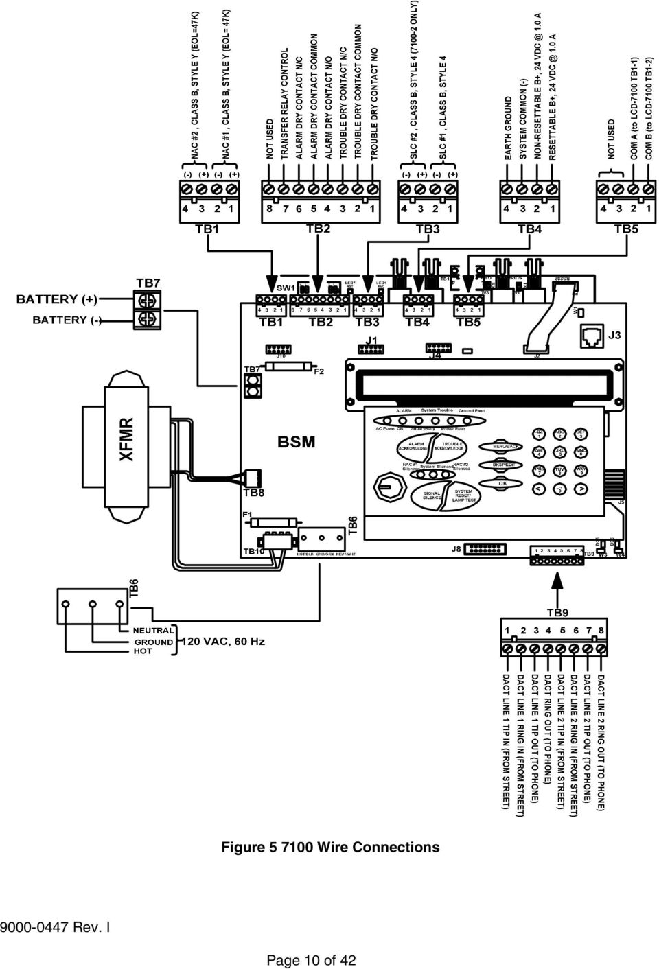
17 3.0 Basic System Module (BSM) Table 3-1 Field Wiring Connections Designation Description Comments TB1-1 NAC Circuit 1 (+) Class B, Style Y TB1-2 NAC Circuit 1 (-) Class B, Style Y TB1-3 NAC Circuit 1 (+) Class B, Style Y TB1-4 NAC Circuit 2 (-) Class B, Style Y TB2-1 TRBL Trouble contacts, N/O, 2 30 VDC (resistive) TB2-2 TRBL Trouble contacts, Common TB2-3 TRBL Trouble contacts, N/C TB2-4 ALM Alarm contacts, N/O, 2 30 VDC (resistive) TB2-5 ALM Alarm contacts, Common TB2-6 ALM Alarm contacts, N/C TB2-7 Transfer control TB2-8 Not used TB3-1 Signaling Line Circuit 1 (+) Class B, Style 4 TB3-2 Signaling Line Circuit 1 (-) Class B, Style 4 TB3-3 Signaling Line Circuit 2 (+) Class B, Style 4 (7100-2, -2D only) TB3-4 Signaling Line Circuit 2 (-) Class B, Style 4 (7100-2, -2D only) TB4-1 Resettable Power, 24 VDC 1.0 amp. TB4-2 Non-resettable Power, 24 VDC 1.0 amp. TB4-3 System Common TB4-4 Earth Ground TB5-1 COM B To LCD-7100 TB1-2 TB5-2 COM A To LCD-7100 TB1-1 TB5-3, -4 Not used TB6-1 AC Hot 120 VAC Hot, 50/60 Hz 2 amp., 240 VAC Hot, 50/60 Hz 1 amp. TB6-2 Ground Ground TB6-3 AC Neutral 120 VAC Neutral, 240 VAC Hot TB7-1 Batt+ Battery terminal (+) TB7-2 Batt- Battery terminal (-) TB9-1 DACT Line 1 Tip In (non-power-limited) From street TB9-2 DACT Line 1 Ring In (non-power-limited) From street TB9-3 DACT Line 1 Tip Out (non-power-limited) To phone TB9-4 DACT Line 1 Ring Out (non-power-limited) To phone TB9-5 DACT Line 2 Tip In (non-power-limited) From street TB9-6 DACT Line 2 Ring In (non-power-limited) From street TB9-7 DACT Line 2 Ring Out (non-power-limited) To phone TB9-8 DACT Line 2 Ring Out (non-power-limited) To phone Page 11 of 42
 TB2-5 ALM Alarm contacts, Common TB2-6 ALM Alarm contacts, N/C TB2-7 Transfer control TB2-8 Not used TB3-1 Signaling Line Circuit 1 (+) Class B, Style 4 TB3-2 Signaling Line")
18 3.1 Power Table 3-2 LEDs Jumpers Designation Description Comments LEDs LED25 Yellow Line 1 Trouble LED26 Yellow Line 2 Trouble Jumpers W1 Not used W2 OUT to disable battery W3 IN No Local Phone Line 1 W4 IN No Local Phone Line 2 J6 Connection to keypad JMP1 Cut for 240 VAC input operation AC Input Connection of the 120/240 VAC, 50/60 Hz power source must be made per the requirements of the National Electrical Code, NFPA 70, Article 760, the applicable NFPA requirements, and/or the Authority Having Jurisdiction. Guidelines to follow are: Connections must be to a dedicated branch circuit. Connections must be mechanically protected. All means of disconnecting the circuit must be clearly marked: FIRE ALARM CIRCUIT CONTROL". Accessible only to authorized personnel. For 240 VAC operation, no conductor shall have a potential greater than 150 V to ground. See Table 3-1 for AC input and battery connections. IMPORTANT: Always apply AC power first, then connect the batteries Battery Connections TB7-1 is positive. See Table 3-1. TB7-2 is negative. See Table 3-1. Observe polarity See Table 3-3 for Battery Calculations Auxiliary Power Output, Resettable/Non-resettable (Special Application) TB4-1 Resettable, 24 VDC, max. 1.0 amp., FWR. Suitable for use with projected beam smoke detectors SPB-24, or DH Series duct detectors. TB4-2 Non-resettable, 24 VDC, max. 1.0 amp., FWR. Suitable for use with the Firemark door holders. NOTE: Total output is 1.0 amp max. combined. TB4-3 Common negative TB4-4 Not used Earth Ground Connection TB4-4 Earth Ground Page 12 of 42

19 3.2 Relay Connections System Trouble Contacts TB2-1 Normally Open TB2-2 Common TB2-3 Normally Closed Transfers on any trouble condition and/or supervisory alarm. System Alarm Contacts TB2-4 Normally Open TB2-5 Common TB2-6 Normally Closed Transfers upon any system alarm except supervisory. Page 13 of 42

20 Table 3-3 Battery Standby Chart Qty Module Description Supv. Current Alarm Current BSM-1 Basic System Module, 1 SLC A A BSM-2 Basic System Module, 2 SLC A A BSM-1D Basic System Module, 1 SLC w/dact A A BSM-2D Basic System Module, 2 SLC w/dact A A PTRM Printer Transient Module A A CAOM Class A Option Module A A MCOM Municipal Circuit Option Module A A LCD-7100 Optional Remote Serial Annunciator A A LDM-7100 LED Driver Module A A* INI-7100 Intelligent Network Interface Module A A Total Supv. Current Total Alarm Current Addressable Modules Smoke and heat sensors Notification Appliances Aux. Power Devices Misc. Devices TOTALS A Total Supv. Current B Enter number of standby hours required** C Multiply Line A times hours in Line B enter D Total alarm current from above E Enter alarm sounding period in hours. (5 minutes =.084 hr.) F Multiply Line D times Line # - enter G Total of Lines C & F enter H Multiply Line G by 1.2 enter (Total ampere/hours required***) NOTE: * With all LEDs and optional buzzer energized. ** 24 hrs for NFPA 72 protected premises or Central Station signaling, or Auxiliary, or Remote Supervising Station Fire Alarm Systems. *** Use the next size battery with a capacity greater than required. Maximum 31 A/H capacity. Page 14 of 42

SFC-200 SERIES FIRE ALARM CONTROL PANELS. SFC-200 Series Fire Alarm Control Panels. Features. Description
 SFC-200 SERIES FIRE ALARM CONTROL PANELS SFC-200 Series Fire Alarm Control Panels Description Summit s SFC-200 Series fire alarm control panels consist of six and twelve zone models which are equipped
FireSeeker Fire Alarm Control Panel Model FS-250 Programming Manual
 FireSeeker Fire Alarm Control Panel Model FS-250 Programming Manual P/N 315-049403-1 Siemens Building Technologies Fire Safety Table Of Contents Introduction...1 The Access levels...1 User Level...1 Maintenance
SECTION 16721 FIRE ALARM AND SMOKE DETECTION SYSTEMS
 SECTION 16721 PART 1 - GENERAL 1.1 SECTION INCLUDES A. Fire Alarm Control Panels B. Manual Fire Alarm Stations C. Automatic Smoke D. Fire Alarm Notification Appliances E. Auxiliary Fire Alarm Equipment
INTELLIGENT FIRE ALARM CONTROL PANELS. MR-2100/MR-2200 Intelligent Fire Alarm Control Panels MEA. Features. Description
 INTELLIGENT FIRE ALARM CONTROL PANELS MR-2100/MR-2200 Intelligent Fire Alarm Control Panels Description MR-2100/MR-2200 Intelligent Fire Alarm Control Panel (shown with optional LED modules) Secutron's
SECTION 16720 - FIRE AND SMOKE ALARM SYSTEM. City of San Diego, CWP Guidelines
 PART 1 -- GENERAL 1.1 WORK OF THIS SECTION SECTION 16720 - City of San Diego, CWP Guidelines A. The WORK of this Section includes providing manual and automatic fire alarm and smoke detection systems meeting
FC-72 SERIES FIRE ALARM SYSTEM
 FC-72 SERIES FIRE ALARM SYSTEM INSTRUCTION/OPERATING MANUAL Copyright 1988 Part Number: 9000-0007 Published in the U.S.A. Version 5.1 All rights reserved Serial Number 301 2nd Ave. Waltham, MA 02451-1133
SECTION 13850 DETECTION AND ALARM
 SECTION 13850 DETECTION AND ALARM PART 1 GENERAL 1.01 SUMMARY A. Section Includes 1. Control Panel 2 Associated Equipment B. Products Installed But Not Supplied Under This Section 1. Section 16140 - Wiring
AC-115 Compact Networked Single Door Controller. Installation and User Manual
 AC-115 Compact Networked Single Controller Installation and User Manual December 2007 Table of Contents Table of Contents 1. Introduction...5 1.1 Key Features... 6 1.2 Technical Specifications... 7 2.
Fire Alarm FAQs. Q: How many zone/circuit fire alarm panel do I need? Q: What candela strobes do I need?
 5/2/2014 Fire Alarm FAQs Question Answer Q: How many zone/circuit fire alarm panel do I need? Q: What candela strobes do I need? A: The size of a fire alarm panel is determined by a number of factors,
HONEYWELL COMMERCIAL FIRE/BURG PANEL UL LISTING REQUIREMENTS (Compiled from VistaFBPT Installation Instructions 800-09617V1 Rev A 11/12)
") HONEYWELL COMMERCIAL FIRE/BURG PANEL UL LISTING REQUIREMENTS (Compiled from VistaFBPT Installation Instructions 800-09617V1 Rev A 11/12) UL864 (Commercial Fire) Compliance General Requirements The VISTA-128FBPT/VISTA250FBPT
HONEYWELL COMMERCIAL FIRE/BURG PANEL UL LISTING REQUIREMENTS (Compiled from VistaFBPT Installation Instructions 800-09617V1 Rev A 11/12) UL864 (Commercial Fire) Compliance General Requirements The VISTA-128FBPT/VISTA250FBPT
DORMA MODEL PS-406BB POWER SUPPLY INSTALLATION INSTRUCTIONS
 Features: INSTALLATION Install in accordance with NFPA 70. DORMA MODEL PS-406BB POWER SUPPLY INSTALLATION INSTRUCTIONS Up to 1.95 Amps Load Capacity Class 2 Rated Outputs Overload, Over Voltage, and Short
TAMARAC FIRE RESCUE INSTRUCTIONS FOR FIRE ALARM PRE-SUBMITTAL CHECKLIST
 TAMARAC FIRE RESCUE INSTRUCTIONS FOR FIRE ALARM PRE-SUBMITTAL CHECKLIST In order to provide a comprehensive plan review in a timely manner, and to insure the design and installation of fire alarm systems
ADT-LCD40 Series Remote Fire Annunciators
 ADT Security Services, Inc. One Town Center Road Boca Raton, FL 33431 Phone: (561) 988-3600 FAX: (561) 988-3675 ADT-LCD40 Series Remote Fire Annunciators for use with Unimode 200 Addressable Fire Alarm
FLORIDA ATLANTIC UNIVERSITY FIRE ALARM SYSTEM INSTALLATION MANUAL
 FLORIDA ATLANTIC UNIVERSITY FIRE ALARM SYSTEM INSTALLATION MANUAL January, 2003 Environmental Health and Safety Florida Atlantic University 777 Glades Rd. Boca Raton, FL 33431 Phone: 561-297-3129 Fax:
FIRE ALARM AND DETECTION SYSTEMS SECTION 16721
 PART 1 - GENERAL 1.01 WORK INCLUDED FIRE ALARM AND DETECTION SYSTEMS SECTION 16721 A. Provide a complete fully addressable, power limited, fire detection and evacuation system. The system shall be connected
HM-W536 Install Guide
 HM-W536 Install Guide 9/13/2013 IMPORTANT SAFETY INSTRUCTIONS Warning - When using electrical devices, basic safety precautions should be followed to reduce the risk of fire, electrical shock or injury.
SILENT KNIGHT MODEL 5207
 SILENT KNIGHT MODEL 5207 Fire Control / Communicator Installation, Programming, and Operation Manual Part Number 150865 Rev. C, 04/03 Contents Section 1 Introduction.......................................................................1-1
FVSU-33201301 REPAIR & UPGRADE FIBER OPTIC 280000-1 SECTION 280000 FIRE ALARM SYSTEM CONNECTIVITY
 FVSU-33201301 REPAIR & UPGRADE FIBER OPTIC 280000-1 SECTION 280000 FIRE ALARM SYSTEM CONNECTIVITY PART 1 - GENERAL 1.1 SUMMARY A. Section Includes: 1. Fire-alarm control unit. 2. Addressable interface
DTW Works Master Specification Version 2006
 Issued 2006/08/01 Section 13852 Multiplex Fire Alarm System Page 1 of 10 PART 1 GENERAL 1.1 RELATED WORK.1 Section 01330 Submittal Procedures..2 Section 01780 Closeout Procedures..3 Section 01810 Commissioning..4
PS-Tools. User s Guide for the 198 Pt Addr Panel
 PS-Tools User s Guide for the 198 Pt Addr Panel Fire Alarm System Limitations While a fire alarm system may lower insurance rates, it is not a substitute for fire insurance! An automatic fire alarm system
Life Alarm Fire Alarm Controls
 FIRE SUPERVISORY SUPV SILENCED SILENCE AC POWER RESET UL, ULC Listed FM Approved MEA Approved* Life Alarm Fire Alarm Controls Fire Alarm Controls 4005 Series Fire Alarm Control Panels Eight through Thirty-Six
SECTION 16721 FIRE ALARM AND DETECTION SYSTEMS
 SECTION 16721 FIRE ALARM AND DETECTION SYSTEMS The equipment requirements of this section apply to the IUB Campus. The IUPUI Campus has a preferred vendor agreement for fire alarm systems. Contact Pat
Fire Alarm System Plans Submittal Guidelines For New and Existing Systems
 Fire Alarm System Plans Submittal Guidelines For New and Existing Systems SCOPE The Temecula Fire Prevention Bureau (TFPB) has established the following requirements for the submittal of all fire alarms,
FIRE ALARM SYSTEM TECHNICAL SPECIFICATIONS Page 1 of 10
 TECHNICAL SPECIFICATIONS Page 1 of 10 FIRE DETECTION AND ALARM SYSTEM Scope Furnish a complete 24V DC conventional, electrically supervised, zone annunciated, fire detection and alarm system as specified
SECTION 16721 FIRE DETECTION AND ALARM SYSTEM PART 1 - GENERAL 1.01 DESCRIPTION
 SECTION 16721 FIRE DETECTION AND ALARM SYSTEM PART 1 - GENERAL 1.01 DESCRIPTION A. This section of the specifications includes the furnishing, installation, and connection of the microprocessor-controlled
Fire Fighter Phone System Installation Instructions
 Fire Fighter Phone System Installation Instructions Introduction This publication describes the installation procedure for the Fire Fighter s Phone on a 4100U or a 4100ES Fire Alarm Control Panel (FACP).
NC State University Design and Construction Guidelines Division 26 Fire Alarm Systems
 NC State University Design and Construction Guidelines Division 26 Fire Alarm Systems 1.0 Purpose A. The following guideline provides the minimum standards and requirements for fire alarm systems. 2.0
Field Charger/Power Supply FCPS-24FS6 & FCPS-24FS8 FCPS-24FS6E & FCPS-24FS8E FCPS-24FS6C & FCPS-24FS8C Installation Manual
 Field Charger/Power Supply FCPS-24FS6 & FCPS-24FS8 FCPS-24FS6E & FCPS-24FS8E FCPS-24FS6C & FCPS-24FS8C Installation Manual Document 51883-L8 7/11/2014 Rev: J2 P/N 51883-L8:J2 ECN 14-570 Fire Alarm & Emergency
SECTION 13850 (28 31 00) FIRE DETECTION AND ALARM SYSTEM
 FIRE DETECTION AND ALARM SYSTEM") SECTION 13850 (28 31 00) FIRE DETECTION AND ALARM SYSTEM ENGINEERING SPECIFICATION 25-POINT INTELLIGENT COMMUNICATING FIRE DETECTION SYSTEM PART 1 GENERAL 1.1. DESCRIPTION: A. This section of the specification
SECTION 13850 (28 31 00) FIRE DETECTION AND ALARM SYSTEM ENGINEERING SPECIFICATION 25-POINT INTELLIGENT COMMUNICATING FIRE DETECTION SYSTEM PART 1 GENERAL 1.1. DESCRIPTION: A. This section of the specification
Fire Alarm System Plans Review Checklist Property location Date of Review
 Fire Alarm System Plans Review Checklist Property location Date of Review 1. Is application completed in entirety? 2. Are the plans review fee submitted with the application? 3. Does floor plan include
INTELLIGENT FIRE ALARM CONTROL UNITS. MMX-2017-12NDS Intelligent Network Fire Alarm Control Unit. Features. Description
 INTELLIGENT FIRE ALARM CONTROL UNITS MMX-2017-12NDS Intelligent Network Fire Alarm Control Unit Description Secutron s MMX-2017-12NDS Network Fire Alarm Control Unit offers modular components to meet a
INSTALLATION GUIDE. Card Reader & Controller with KIM Swipe Reader for Solitaire 850 / 950 / 850L Learnlok PK2930
 INSTALLATION GUIDE Card Reader & Controller with KIM Swipe Reader for Solitaire 850 / 950 / 850L Learnlok PK2930 Card Reader and Controller Model 3.5 with KIM Swipe Reader Table of Contents 1. Features..................................
CITY OF PHILADELPHIA DEPARTMENT OF LICENSES AND INSPECTIONS ANNUAL CERTIFICATION FOR FIRE ALARM SYSTEMS
 CITY OF PHILADELPHIA DEPARTMENT OF LICENSES AND INSPECTIONS ANNUAL CERTIFICATION FOR FIRE ALARM SYSTEMS PROPERTY ADDRESS (BRT Address Required) TESTING CONTRACTOR (Name and Address) License No. ANNUAL
SECTION 16700 FIRE ALARM SYSTEM
 SECTION 16700 FIRE ALARM SYSTEM PART ONE: GENERAL 1.1 GENERAL REQUIREMENTS A. Definition of Work : This section of the specification includes the furnishing, installation, connection and testing of the
E-PDD Duct Smoke Detector Installation Sheet
 E-PDD Duct Smoke Installation Sheet Operation The duct smoke detector's primary purpose is to provide early warning of an impending fire and shut down the HVAC unit in order to prevent smoke from circulating
INSTRUCTIONS FOR BUILDINGS WITH FIRE PROTECTION EQUIPMENT
 INSTRUCTIONS FOR BUILDINGS WITH FIRE PROTECTION EQUIPMENT FIRE EXTINGUISHERS,SPRINKLER SYSTEMS AND FIRE ALARMS Attachment #1 Inspection of Fire Extinguishers Fire Extinguishers must be tested according
USER INSTRUCTIONS CONTENTS
 CONTENTS Full Set [1]...2 Part Set [2]...2 Night Set [3]...3 Unsetting...3 Unsetting after or during an alarm...3 Testing the system [5]...3 Isolating zones [6]...4 Reprogramming codes [8]...4 Chime facility
Small Building Life Safety Solutions. GE Security. Affordable FireShield Conventional Fire Alarm Control Panels. imagination at work
 GE Security Small Building Life Safety Solutions Affordable FireShield Conventional Fire Alarm Control Panels imagination at work cost Location: Environment: Solution: Flower shop Finely decorated, gentle
FIRE ALARM SYSTEM. A. Shop drawings shall be submitted as follows: 1. Manufacturer's published literature. for aspproval.
 Polk School District Specifications for the New Fire Alarm in the Existing Building Eastside Elementary School FIRE ALARM SYSTEM 1.01 SUBMITTALS A. Shop drawings shall be submitted as follows: 1. Manufacturer's
SECTION 16721 FIRE ALARM AND DETECTION SYSTEM
 1. GENERAL 1.1. Related Documents: 1.2. Scope: 1.1.1. The general provisions of the Contract, including General and Supplementary Conditions and General Requirements apply to the work specified in this
466-1936 Rev E October 2004 ZZZ*(6HFXULW\FRP. Part No: 60-883-95R. CareGard. User Guide
 ) *(6HFXULW\ 466-1936 Rev E October 2004 ZZZ*(6HFXULW\FRP Part No: 60-883-95R CareGard User Guide FCC Notices FCC Part 15 Information to the User Changes or modifications not expressly approved by GE Security
MODEL 5010 DUAL CHANNEL SMOKE/FIRE DETECTION MODULE
 DESCRIPTION MODEL 5010 DUAL CHANNEL SMOKE/FIRE DETECTION MODULE DESCRIPTION The SST Model 5010 Two Channel Smoke/Fire Detection Module provides two independent detection input channels for the NOVA-5000
Module 4, Lesson 12 Fire Alarm Systems
 Student Manual Module 4, Lesson 12 Fire Alarm Systems Performance Objectives At the conclusion of this lesson, you will be able to: Identify the components and functions of a fire alarm system and determine
PN 15153:G1 ECN 02-539. Fire Alarm Control Panel MS-4424. Instruction Manual. Document 15153 10/22/2002 Rev: G
 PN 15153:G1 ECN 02-539 Fire Alarm Control Panel MS-4424 Instruction Manual Document 15153 10/22/2002 Rev: G Fire Alarm System Limitations An automatic fire alarm system typically made up of smoke detectors,
QMT-5300A, QMT-5302 and QZT-5302
 Advanced Life Safety Solutions QMT5300A, QMT5302 and QZT5302 Firefighters Telephone System COMMON TEL. TROUBLE MASTER TEL. TROUBLE INCOMING CALL CONNECT/ CLEAR ALL LAMP TEST Installation & Operation Instructions
SFC-200 SERIES LCD FIRE ALARM PANEL
 SFC-200 SERIES LCD FIRE ALARM PANEL User Guide LT-954SUM SFC-200 Series LCD Version User Guide Contents Introduction... 1 About this Manual... 1 Technical Support... 1 Main Display... 1 The Buzzer and
FA-300 Series. LCD Fire Alarm Control Panel. User Guide. LT-954 Rev. 0.1 February 2013. FA-300 SERIES Fire Alarm Control Panel
 ABC DEF GHI JKL MNO PQR STU YZ WXY FA-300 Series LCD Fire Alarm Control Panel Advanced Life Safety Solutions System Normal 10:36AM WED 2003-10-01 SYSTEM RESET A.C. ON ALARM SUPV TRBL CPU FAIL SIGNAL SILENCE
SECTION 13850 (28 31 00) FIRE DETECTION AND ALARM SYSTEM
 FIRE DETECTION AND ALARM SYSTEM") SECTION 13850 (28 31 00) FIRE DETECTION AND ALARM SYSTEM ENGINEERING SPECIFICATION INTELLIGENT REPORTING FIRE DETECTION SYSTEM PART 1 GENERAL 1.1 DESCRIPTION A. This specification includes the furnishing,
SECTION 13850 (28 31 00) FIRE DETECTION AND ALARM SYSTEM ENGINEERING SPECIFICATION INTELLIGENT REPORTING FIRE DETECTION SYSTEM PART 1 GENERAL 1.1 DESCRIPTION A. This specification includes the furnishing,
Control Panels D9412GV3/D7412GV3/D7212GV3. UL Installation Instructions
 Control Panels D9412GV3/D7412GV3/D7212GV3 en UL Installation Instructions Control Panels Table of Contents en 3 Table of Contents 1 Installation 4 1.1 Installation Preparation 4 1.2 Enclosure Options
CLARK COUNTY FIRE DEPARTMENT Fire Hazard & Prevention Services
 CLARK COUNTY FIRE DEPARTMENT Fire Hazard & Prevention Services 575 E. Flamingo Road, Las Vegas, NV 89119 (702) 455-7316 FAX (702) 455-7347 105.8a-6.1 TITLE: FIRE ALARM SYSTEM REQUIREMENTS SCOPE: This guideline
SECTION 16721 FIRE ALARM AND DETECTION SYSTEM
 SECTION 16721 FIRE ALARM AND DETECTION SYSTEM PART 1 - GENERAL 1.1 RELATED DOCUMENTS: A. Drawings and general provisions of Contract, including General and Supplementary Conditions and Division-1 Specification
PC Tab Security System INSTRUCTION MANUAL
 PC Tab Security System INSTRUCTION MANUAL This manual is intended as a Quick Start manual covering the basic functions that have been enabled on the alarm panel. The alarm panel is capable of extensive
1.0 General. Inspection, Testing, and Maintenance 1 of 8
 1.0 General 1.1 Scope This specifications covers the minimum requirements for the inspection, testing, and maintenance of the existing Notifier fire alarm systems at Bergen Community College (BCC) campus
4100U/4100ES to TFX Fire Fighter Phone System Installation Instructions
 4100U/4100ES to TFX Fire Fighter Phone System Installation Instructions Introduction This publication describes the installation procedure for the 4100U/4100ES to TFX Fire Fighter s Phone card used to
EST io64 and io500 Technical Reference Manual
 GE Security EST Fire & Life Safety EST io64 and io500 Technical Reference Manual P/N 3101112 REV 2.0 ISS 30JUL08 Copyright Copyright 2008 GE Security, Inc. All rights reserved. This document may not be
FIRE ALARM AND EMERGENCY COMMUNICATION SYSTEM RECORD OF COMPLETION
 FIRE ALARM AND EMERGENCY COMMUNICATION SYSTEM RECORD OF COMPLETION To be completed by the system installation contractor at the time of system acceptance and approval. It shall be permitted to modify this
INTELLIKNIGHT MODEL 5808
 INTELLIKNIGHT MODEL 5808 Addressable Fire Control Panel Installation and Operations Manual Part Number 151274 Rev K Installation Procedure Adherence to the following will aid in problem-free installation
SECTION 28 31 11 FIRE ALARM AND DETECTION SYSTEM
 KNOXVILLE, TENNESSEE SECTION 28 31 11 PAGE 1 PART 1 - GENERAL 1.01 DESCRIPTION OF WORK SECTION 28 31 11 A. Extent of fire alarm and detection system work shall be as described in this specification, as
Installation Instructions & Owner s Operation Manual for Two to Eight Zone 2400 Series Fire Alarm Control Panels
 Installation Instructions & Owner s Operation Manual for Two to Eight Zone 2400 Series Fire Alarm Control Panels P/N 46000-1320, Rev. 1.6 Edwards This product has been designed to meet the requirements
How To Power A Power Control On An Ip40 (Ipl) With A Power Supply (Iplug) With An Ip20 Controller (Iphones) With Power Control (Power Control) With No Antenna) With The Ip20 (Power)
 With A Power Supply (Iplug) With An Ip20 Controller (Iphones) With Power Control (Power Control) With No Antenna) With The Ip20 (Power)") MODEL NUMBER: ISC910-1-0-GB-XX ISC911-5-0-GB-XX IXP20 CONTROLLER SPECIFICATIONS Working Environment Plastic Housing... Power ImproX IXP20 Controller INSTALLATION MANUAL Designed to work in an indoor (dry)
MODEL NUMBER: ISC910-1-0-GB-XX ISC911-5-0-GB-XX IXP20 CONTROLLER SPECIFICATIONS Working Environment Plastic Housing... Power ImproX IXP20 Controller INSTALLATION MANUAL Designed to work in an indoor (dry)
SECTION 16853 ZONED (DC LOOP) FIREALARM SYSTEM
 FIREALARM SYSTEM") SECTION 16853 ZONED (DC LOOP) FIRE-ALARM SYSTEM PART 1 - GENERAL 1.1 RELATED DOCUMENTS A. Drawings and general provisions of the Contract, including General and Supplementary Conditions and Division 1
SECTION 16853 ZONED (DC LOOP) FIRE-ALARM SYSTEM PART 1 - GENERAL 1.1 RELATED DOCUMENTS A. Drawings and general provisions of the Contract, including General and Supplementary Conditions and Division 1
MCR1900 Media Converter 19-Slot Chassis
 MCR1900 Media Converter 19-Slot Chassis Installation Guide Part #5500304-11 Copyright Statement This document must not be reproduced in any way whatsoever, either printed or electronically, without the
Changes or modifications not expressly approved by Interactive Technologies, Inc. can void the user s authority to operate the equipment.
 0 FCC Notices FCC Part 15 Information to the User Changes or modifications not expressly approved by Interactive Technologies, Inc. can void the user s authority to operate the equipment. FCC Part 15 Class
EVC40 EMERGENCY VOICE COMMUNICATION SYSTEM
 EVC40 EMERGENCY VOICE COMMUNICATION SYSTEM INSTALLATION MANUAL Protec Fire Detection PLC, Protec House, Churchill Way, Nelson, Lancashire, BB9 6RT. Telephone: +44 (0) 1282 717171 Fax: +44 (0) 1282 717273
User Guide for the DS7060 Control/Communicator
 DS7060 User Guide Copyright 1996-97 Detection Systems, Inc. User Guide for the DS7060 Control/Communicator Copyright 1996-97 Detection Systems, Inc. Detection Systems, Inc., 130 Perinton Parkway, Fairport,
Fire Alarm Control Panel. Family. Operating Manual
 Fire Alarm Control Panel Family Operating Manual CONTENTS System Description AH-03312 System Characteristics... Fire Signal Receiving Board Description-4L... Fire Signal Receiving Board Description-8L...
Dialog Telephone Interface Module Installation Sheet
 Dialog Telephone Interface Module Installation Sheet Description The Dialog Telephone Module (DTIM), model number 60-879- 95R, is a battery operated communication link between the security system control
Square D Clipsal DIN-Rail Four-Channel Auxiliary Input Unit
 Square D Clipsal DIN-Rail Four-Channel Auxiliary Input Unit SLCLE5504AUX for Use with Wired C-Bus Networks Instruction Bulletin Retain for future use. Square D Clipsal DIN-Rail Four-Channel Auxiliary Input
Operating the DS9400 Fire Alarm Control/Communicator
 TM 255 DETECTION SYSTEMS Power Alarm Troubl Silenced Supervised TM 255 DS9400 FIRE CONTROL/COMMUNICATOR Operating the DS9400 Fire Alarm Control/Communicator Outline I. Description II. Features III. Installation
DELAWARE STATE FIRE MARSHAL FIRE ALARM SYSTEM CERTIFICATE OF INSTALLATION
 Phone System Owner Phone System Engineered by: of Record Drawings: of System Manuals: of Test Reports: System Installer 1. GENERAL INFORMATION Phone Delaware License No: Certificate Holder No. System Supplier
PLAN REVIEW GUIDE FOR FIRE ALARM
 PLAN REVIEW GUIDE FOR FIRE ALARM PROJECT NAME: PERMIT # PROJECT ADDRESS: CONTACT PERSON: PHONE Fire alarm system installation information shall be provided on the appropriate architectural and electrical
Attachment 9. Trouble signals. Interfaced equipment. Primary (main) power supply
 power supply") FIRE DETECTION, ALARM AND MASS NOTIFICATION SYSTEMS Inspection, testing, and maintenance of fire detection, alarm and Mass Notification systems shall be performed in accordance with the manufacturer's
FIRE DETECTION, ALARM AND MASS NOTIFICATION SYSTEMS Inspection, testing, and maintenance of fire detection, alarm and Mass Notification systems shall be performed in accordance with the manufacturer's
PN: 50066:D2 ECN 02-606. Fire Control Communicator MS-5024/MS-5024E. Document #50066 12/03/02 Rev.
 PN: 50066:D2 ECN 02-606 Fire Control Communicator MS-5024/MS-5024E Document #50066 12/03/02 Rev. D Fire Alarm System Limitations An automatic fire alarm system typically made up of smoke detectors, heat
Advantium 2 Plus Alarm
 ADI 9510-B Advantium 2 Plus Alarm INSTALLATION AND OPERATING INSTRUCTIONS Carefully Read These Instructions Before Operating Carefully Read These Controls Corporation of America 1501 Harpers Road Virginia
Fire Alarm Communicator 411UDAC. Manual. Document 51073 6/27/2014 Rev: F P/N 51073:F ECN 14-545
 Fire Alarm Communicator 411UDAC Manual Document 51073 6/27/2014 Rev: F P/N 51073:F ECN 14-545 Fire Alarm & Emergency Communication System Limitations While a life safety system may lower insurance rates,
Control Panel. D9412GV4/D7412GV4 v2.03. en UL Installation Instructions
 Control Panel D9412GV4/D7412GV4 v2.03 en UL Installation Instructions Control Panel Table of Contents en 3 Table of contents 1 Introduction 5 1.1 About documentation 5 1.2 Bosch Security Systems, Inc.
HP UPS R1500 Generation 3
 HP UPS R1500 Generation 3 Installation Instructions Part Number 650952-001 NOTE: The rating label on the device provides the class (A or B) of the equipment. Class B devices have a Federal Communications
HERNANDO COUNTY FIRE ALARM GUIDELINES
 HERNANDO COUNTY FIRE ALARM GUIDELINES To be used for all commercial building fire alarm system plan review. The procedures set forth in this document are the minimum requirements necessary to ensure a
FIRE ALARM SYSTEMS PERMIT APPLICATION, PLAN SUBMITTAL, DESIGN, INSTALLATION AND INSPECTION REQUIREMENTS Effective Date: January, 2011
 Office of the Fire Marshal 1.0 PERMITS FIRE ALARM SYSTEMS PERMIT APPLICATION, PLAN SUBMITTAL, DESIGN, INSTALLATION AND INSPECTION REQUIREMENTS Effective Date: January, 2011 1.1 To acquire an installation
D7050/D7050TH. Installation Instructions. Multiplex Photoelectric Smoke Detectors
 D7050/D7050TH EN Installation Instructions Multiplex Photoelectric Smoke Detectors D7050/D7050TH Installation Instructions.0 Description Notices These instructions cover the installation of the D7050/D7050TH
Release Control Fire Alarm Systems
 SYSTEM ABORT PUSH AND HOLD COIL SUPERVISION MODULE (2 AMP) 2081-9046 RED INSTALLATION INSTRUCTIONS 574-437 REV YEL NAC+ MAINTAIN 1/4" SEPARATION BETWEEN POW ER LIMITED (RED/) AND NONPOWER S LIMITED (YEL/)
Control/Communicator Installation Manual
 DAS NETWORX NX-8 Control/Communicator Installation Manual Page General Description... 2 Ordering Information... 2 Option Definitions... 2 Programming the LED Code Pads... 4 Programming the NX-8... 8 Types
BLACK BOX. T1/E1 Link Extenders OCTOBER 2007 MT195A-T1 MT196A-E1
 BLACK BOX NETWORK SERVICES OCTOBER 2007 MT195A-T1 MT196A-E1 T1/E1 Link Extenders Important This is a Class A device and is intended for use in a light industrial environment. It is not intended nor approved
MAKING MODERN LIVING POSSIBLE. AK-SC255 On-Site Installation Guide DANFOSS ELECTRONIC CONTROLS & SENSORS
 MAKING MODERN LIVING POSSIBLE AK-SC255 On-Site Installation Guide DANFOSS ELECTRONIC CONTROLS & SENSORS How to Use This Guide Read this Guide completely as you install and start up your new AK-SC 255 controller.
WIRELESS STATUS MONITOR
 INSTALLATION INSTRUCTIONS WIRELESS STATUS MONITOR (WSM or AUWSM) The most current version of this document is available for download at: http://www.ir-swa.com P/N: M053-032-D Schlage 245 W. Roosevelt Road,
Conventional Fire Detection and Extinguishant Control System Specification
 Conventional Fire Detection and Extinguishant Control System Specification Page 1 of 9 Scope Furnish a complete 24VDC Conventional, electrically supervised, combined fire detection and extinguishant release
FIRE ALARM SYSTEM CHECKLIST For Addressable Systems PRIOR TO INSPECTION
 Building Name/Location: Installing Company: Observation By: Date: Time: 1 Building Occupants, Authorities and Alarm Monitoring Co Have Been Notified 2 FACP Manufacturer and Panel is Approved for NCSU Campus
T7560A,B,C Digital Wall Module
 T7560A,B,C Digital Wall Module HONEYWELL EXCEL 5000 OPEN SYSTEM BEFORE INSTALLATION All wiring must comply with local electrical codes and ordinances or as specified on installation wiring diagrams. Digital
C. Conform to requirements of Americans with Disabilities Act (ADA).
.") SECTION 28 31 00 - FIRE ALARM AND DETECTION SYSTEMS PART 1 - GENERAL 1.1 SECTION INCLUDES A. Fire alarm and detection systems 1.2 REFERENCES A. NFPA 70 - National Electrical Code B. NFPA 72 - National
SECTION 28 31 00 - FIRE ALARM AND DETECTION SYSTEMS PART 1 - GENERAL 1.1 SECTION INCLUDES A. Fire alarm and detection systems 1.2 REFERENCES A. NFPA 70 - National Electrical Code B. NFPA 72 - National
ADSL Modem Installation Guide. Model # 36R515 Part # 030-300108 Rev. D Revision Date 12/2000. ADSL Modem Installation Guide
 ADSL Modem Installation Guide Model # 36R515 Part # 030-300108 Rev. D Revision Date 12/2000 ADSL Modem Installation Guide Installation Instructions Westell ADSL Modem 1. Package Inspection and Contents...2
FIRE ALARM SYSTEM RECORD OF COMPLETION
 FUNDAMENTALS OF FIRE ALARM SYSTEMS 72 33 FIRE ALARM SYSTEM RECORD OF COMPLETION To be completed by the system installation contractor at the time of system acceptance and approval. 1. PROTECTED PROPERTY
Installation Instructions for FT-10 Network PowerCommand ATS Communication Module (NCM) Kits 541 0812 and 541 0868
 Kits 541 0812 and 541 0868") Instruction Sheet 10-2004 Installation Instructions for FT-10 Network PowerCommand ATS Communication Module (NCM) Kits 541 0812 and 541 0868 PowerCommand is a registered trademark of Cummins Inc. InPower
Instruction Sheet 10-2004 Installation Instructions for FT-10 Network PowerCommand ATS Communication Module (NCM) Kits 541 0812 and 541 0868 PowerCommand is a registered trademark of Cummins Inc. InPower
D287/D288/D292/D293A/D293E
 D87/D88/D9/D9A/D9E EN Installation Guide Smoke Detector Bases D87/D88/D9/D9A/D9E Installation Guide.0 Overview.0 Overview The D87/D88/D9/D9A/D9E Smoke Detector Bases are designed for use with the D8 Ionization
How To Understand Your Fire Alarm On An Iphone Or Ipad (Powerbook)
") FX-350/351/353 Series Analog/Addressable Fire Alarm Control Panel User Guide LT-965 Rev. 2 May 2013 FX-350/351/353 Series User Guide Table of Contents Introduction... 1 About this Manual... 1 Technical
FX-350/351/353 Series Analog/Addressable Fire Alarm Control Panel User Guide LT-965 Rev. 2 May 2013 FX-350/351/353 Series User Guide Table of Contents Introduction... 1 About this Manual... 1 Technical
Master Time Clock MTC-200 MTC-400 MTC-600. Users Manual
 Master Time Clock MTC-200 MTC-400 MTC-600 Users Manual Toll Free (888)713-0373 Phone (972)987-4408 FAX (877)720-9291 www.midwest-time.com sales@midwest-time.com TABLE OF CONTENTS TOPIC PAGE GENERAL DESCRIPTION
FIRE ALARM SYSTEM RECORD OF COMPLETION
 FIRE ALARM SYSTEM RECORD OF COMPLETION To be completed by the system installation contractor at the time of system acceptance and approval. 1. Protected Property Information Name of property: Description
CM705B - Universal Expander Module CM707B - Plug On Zone Expander Security Systems
 CM705B - Universal Expander Module CM707B - Plug On Zone Expander Security Systems EN Security System CM705B CM705B - Universal Expander Module The CM705B universal expander provides a cost effective way
VFR-400 Installation, Operation, and Instruction Manual
 VFR-400 Installation, Operation, and Instruction Manual Releasing Panel for Sprinkler Systems All specifications subject to revision. Manual #5403548 Rev. Q 10/11 NOTES: i Table of Contents Operating
Model 70A00-1. GSM Cellular Communications Center
 Home Automation, Inc. Model 70A00-1 GSM Cellular Communications Center Operation Manual Document Number 70I00-1 Rev A August, 2009 Contents Description... 1 Use with security systems...1 Everyday use...2
Firmware version: 1.10 Issue: 7 AUTODIALER GD30.2. Instruction Manual
 Firmware version: 1.10 Issue: 7 AUTODIALER GD30.2 Instruction Manual Firmware version: 2.0.1 Issue: 0.6 Version of the GPRS transmitters configurator: 1.3.6.3 Date of issue: 07.03.2012 TABLE OF CONTENTS