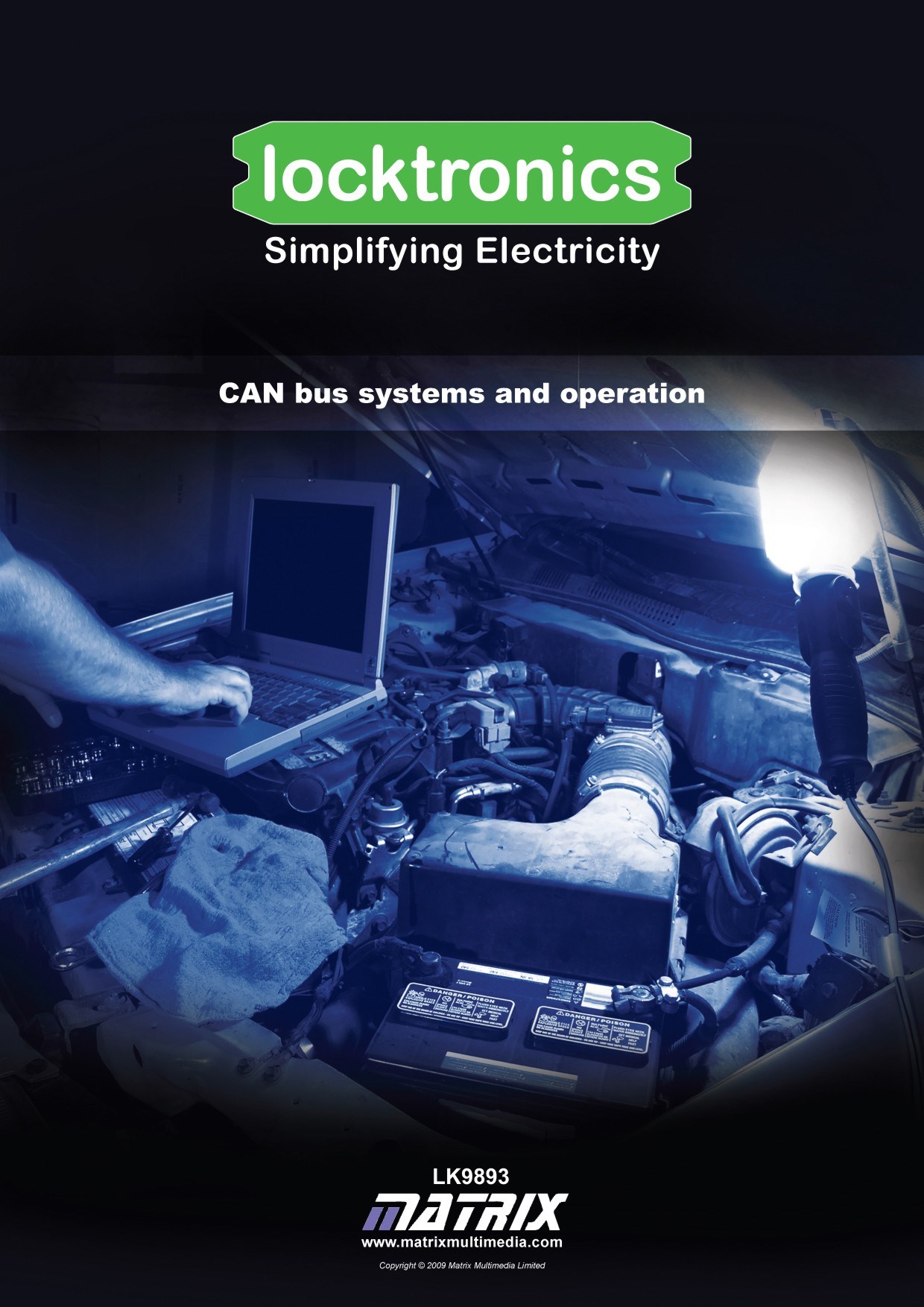
CAN bus systems and operation
|
|
|
- Vanessa Thompson
- 9 years ago
- Views:
Transcription

1 Page 1
2 Page 2 Contents Introduction 3 Overview 4 Building Node A 5 Building Node B 6 Building Node C 7 Building Node D 8 Building the Scan/Fuse Node 9 Wiring It All Up 10 Worksheet 1 - The Startup Routine 11 Worksheet 2 - Seeing the Messages 12 Worksheet 3 - Receiving Messages 14 Worksheet 4 - System Monitoring and Pinging 15 Worksheet 5 - System Faults 16 Worksheet 6 - Circuit Faults 18 Worksheet 7 - Fault Diagnosis Using Charts 19 Worksheet 8 - Build Your Own Car! 20 Instructor Guide 21 Scheme of Work 25 Message Code Summary 31 Kvaser Analyser Set Up 32 System Graphics 34 About this document: Code: LK9893 Developed for product code LK Date Release notes Release version First version released LK revision MIAC programming notes included LK revision Programming notes revised LK Warning that some faults require reprogramming LK Updated sensing resistors and diagrams LK

3 Page 3 Introduction What is this all about? The CAN in CAN bus stands for Controller Area Network and bus a bundle of wires. CAN bus is a fast computer data bus similar to the network used for linking computers. Its use in cars greatly reduces the number and weight of wires used, simplifies construction, reduces cost and allows the use of advanced features, in troubleshooting and monitoring the automotive system. The flexibility and power of the CAN standard brings many advantages to modern automotive systems. However it can seem like a black art. This course is designed to introduce you to the technology involved in CAN bus systems, and reveal some of its magic! The hardware: The course looks at the role of Electronic Control Units (ECUs), linked by a CAN bus, in controlling automotive systems. Modern motor vehicles can contain over a hundred ECUs, controlling everything from the Antilock Braking System (ABS) to the position of the driver s seat. software to control the devices attached to it, and to communicate, using the CAN protocol, with other ECUs. In this course, MIACs (Matrix Industrial Automotive Controllers) are used as ECUs. Each MIAC is running a program that allows you to make it act as one of five types of node. These types are described in the following sheets. Using these, you will: construct and test a number of ECU nodes, using Locktronics equipment, wire these up into a single CAN bus system, carry out a range of tests on the whole system. In doing so, you will learn about: the role of the ECU; the structure of CAN bus systems; the CAN bus message format the use of scan tools in fault diagnosis. An ECU contains a microprocessor, running
4 Page 4 Overview Node by node Your group is going to build five nodes. These are: Node A - the front ECU and circuit, (side lights, headlights, indicators, wipers and horn,) Node B - the instrument panel ECU and circuit, (lighting switches, horn switch, wiper speed controller, indicator switches, and warning LEDs,) Node C - the power train ECU and circuit, (reversing switch, brake light switch, engine temperature sensor and oil pressure sensor,) Node D - the rear ECU and circuit, (side lights, indicators, brake lights, reversing light, fuel level sensor,) Scan/fuse - the system controller and scan tool, fuse box and power relay The number of nodes, and how they are configured, varies greatly from one car to another. Different manufacturers use different software, and different messages within their CAN bus systems. The system used in this course is broadly representative of systems found in cars. Each node consists of an ECU and the associated circuitry required to control the devices attached to that node. Each node is supplied with power, ground and the two wires, called CAN High (CANH) and CAN Low (CANL). In motor vehicles, these CAN wires are twisted together. Note - The Scan/fuse node is not present as such in a car. It is included to allow us to control the overall system and to provide tools to help you understand what is happening. The whole system can be seen in the diagram above. Do not worry if this looks very complicated - all the wiring will be explained as the course progresses. Your instructor will provide your group with a larger version of this picture.
5 Page 5 Building Node A The following pages describe how to build and test each of the five nodes, consisting of an ECU and the associated circuit to control the components attached to the node. All MIAC units are programmed with the same Flowcode program, called LK8902. Users will choose the function of each ECU unit from a menu offered on power up. Over to you: 1. Wire up a MIAC unit and Locktronics equipment, as shown in the diagram on the right. This mimics the circuit you might find on the front of a car. 2. Set the voltage on the power supply to 12V. 3. Switch on. You will see a message: Locktronics LK8902 CAN bus systems dnd followed by: Select a node A Node A represents the front ECU. The lamps on this node mimic the side lights, headlights and indicators. The motor represents the windscreen wiper motor. The buzzer represents the horn. 4. Press the OK button to select node A. 5. You should see a message: Node A F1: Node test F2: CAN system OK: Change node Press the F1 button on the MIAC 6. The motor, each indicator and each pair of headlamps should come on in turn with the appropriate message on the MIAC unit. If the motor does not turn, or the lamps fail to light then check your wiring. 7. Press the reset button (top right on the MIAC) to stop the test.
6 Page 6 Building Node B This node represents the ECU that controls the instrument panel. To help you keep track of the functions of the various switches you may wish to label each Locktronics switch carrier with its function. The switches on this node mimic (left to right) side lights, headlights, left indicator, right indicator, horn and wipers. The potentiometer controls wiper speed. The left hand LED is the fault light which illuminates whenever a fault is detected. It will not go off until the fault is reset on the Scan/fuse node. The LED on the right represents the low fuel warning light. Over to you: 1. Wire up a MIAC and the circuit shown opposite for Node B. This circuit mimics the switches and controls on the instrument panel. 2. Set the voltage on the power supply to 12V. 3. Switch on. 4. Select Node B from the menu system using the up / down keys on the MIAC. 5. You will see the message: Node B F1: Node test F2: CAN system OK: Change node Press the F1 button on the MIAC 6. Look at the MIAC panel and check that each switch and the potentiometer are performing their appropriate functions. The potentiometer should give a readout of 0 (minimum) to 255 (maximum). If the circuit does not function as expected then check your wiring. 7. Press the reset button (top right on the MIAC) to stop the test.
7 Page 7 Building Node C This node represents the ECU that controls the power train. In motor vehicles, this ECU controls functions such as fuel injection and ignition timing. The switches on this node (left to right) mimic the reverse switch in the gearbox, and the brake switch on the brake pedal. The two potentiometers represent the engine temperature sensor and oil pressure sensor. Over to you: 1. Wire up a MIAC and the circuit shown opposite for Node C. This circuit mimics some of the switches and sensors that are connected to the power train ECU. 2. Set the voltage on the power supply to 12V. 3. Switch on. 4. Select Node C from the menu system using the up / down keys on the MIAC. 5. You will see the message: Node C F1: Node test F2: CAN system OK: Change node Press the F1 button on the MIAC 6. Look at the MIAC panel and check that each switch and the potentiometer are mimicking their appropriate functions. The potentiometer should give a readout of around 21 (minimum) to 234 (maximum). 7. Press the reset button (top right on the MIAC) to stop the test.
8 Page 8 Building Node D This node represents the ECU that controls the functions at the back of the motor vehicle. These are usually mainly lighting components. The lamps on this node mimic the various lamps controlled by the rear ECU: side lights, indicators, brake lights and a reversing light. The potentiometer represents a fuel sensor. Over to you: 1. Wire up a MIAC and the circuit shown opposite for Node D, which mimics the indicators and sensors connected to the Rear ECU. 2. Set the voltage on the power supply to 12V. 3. Switch on. 4. Select Node D from the menu system using the up / down keys on the MIAC. 5. You should see a message: Node D F1: Node test F2: CAN system OK: Change node Press the F1 button on the MIAC 6. Look at the MIAC panel and check that the potentiometer is mimicking the fuel sensor. Check that all the lamps are working - if not then check your wiring. 7. Press the reset button (top right on the MIAC) to stop the test.
9 Page 9 Building the Scan/fuse Node This node is not found in the motor vehicle itself, but may be part of the troubleshooting equipment used by mechanics to locate faults. The equipment attached to this ECU represents a basic fuse box. You would not find a single power relay like this in a car - but it helps to control this system. The first fuse limits the current into the overall system, and each additional fuse limits the current to a particular node. Over to you: 1.Wire up a MIAC and the circuit shown opposite for the Scan/fuse node. The circuit connected to the MIAC mimics the fuse box. The switch represents the ignition key which controls the power supplied, via the relay and fuses, to each of the ECUs in the system. This MIAC monitors the other nodes. It does not play a part in controlling any functions in the automotive system. It will be used later on in the course to insert faults and to monitor CAN signals. 2.Set the voltage on the power supply to 12V. 3.Switch on. 4.Select Admin from the menu system using the MIAC s up / down keys. 5.You will see the message: Admin node 6.Check that you can scroll through the six options on the menu using the up / down keys. 7.Check that your circuit is working by checking the output voltages on the fuses using a multimeter.
10 Page 10 Wiring It All Up Your group now has wired up and tested the individual nodes of the CAN bus system. Next, you need to connect them all together. Over to you: The power supply: All nodes will receive power from the fuse box attached to the Scan/fuse node. 1. With the power supply turned off, connect a 12V power supply to the MIAC and relay on the Scan/fuse node. 2. Connect wires from each fuse to power one of the nodes A to D. In this way, each ECU has its own fuse. 3. Connect the 0V terminals on all nodes together. 4. Switch on the power supply. If you have wired everything up correctly the power LED on each MIAC will light up. If not, then check your wiring. 5. Switch off. Connecting the CAN bus The CAN bus consists of just two wires. CAN H (for CAN High) and CAN L (for CAN Low). In a motor vehicle, these are normally very fine wires that are twisted together - known as a twisted pair. The nodes are wired in parallel, i.e. CAN H of node D is connected to CAN H of nodes A, B and C. CAN L is wired up in the same way. Notice that there is no physical hierarchy in the CAN bus system - no central server. All nodes have equal status. For clarity, use blue wires for CANH and yellow wires for CANL connections. The CAN bus requires a 100 resistor, connected between CAN H and CAN L, at each end of the CAN bus, as shown in the diagram: 100ohm ECU ECU ECU ECU ECU These resistors absorb the energy of the data signals, and prevent reflections back down the bus. The MIACs contain suitable resistors, connected internally between the CAN H and CAN L wires. 6. On the Scan/fuse node and on node D, turn the CAN termination switch to the ON position. 7. Check that the CAN termination on the other MIACs is switched off. 8. The system is now ready for testing. 100ohm

11 Page 11 Worksheet 1 The Startup Routine All MIAC units are running the same program. The hardware inside each MIAC is the same. They carry out different functions, as separate nodes, because of choices you made when the nodes were set up. These choices are stored in memory, so that the MIAC remembers what functions to carry out when power is restored. Over to you: 1. Set the voltage on the power supply to 12V. 2. Switch on and check that the power LED on each MIAC is lit. 3. Each MIAC ECU should display: Node X F1: Node test F2: CAN system OK: Change node Select F2 to make the MIAC mimic the preset CAN bus function. Note: Carry out this step last on Node C, as node C runs the Startup routine. In the Startup routine one ECU in the system is programmed to check that all of the other ECUs are present. Node C - the power train ECU - is often given this task. It sends a message on the CAN bus to each node in turn and waits for a reply. It will display Checking Node X and then verify the presence of each node in turn. 4. Check that each node is registered. 5. Switch off. 6. Remove the fuse carrier for Node D 7. Switch on and select F2 to initialise each node, but do Node C last. 8. Look at the messages displayed on Node C. 9. Switch off, and replace the fuse carrier. 10.Repeat step What is the status of the fault light on Node B? 12.Discuss what should happen when a fault like this is detected. Should the car start? Should it be disabled? What level of fault should be tolerated? What faults are critical? 13.On the Scan/fuse Node menu, use the up /down keys to select Release flts. 14.You will then see a sub menu: Get fault info Clear all faults 15.Select Clear all faults and then press F2. The fault light on Node B will go off.
12 Page 12 Worksheet 2 Seeing the Messages The Scan/fuse Node takes no part in controlling components in our CAN bus system. It is just another computer connected to the CAN bus, which helps us to see what is going on in the system. It has some features that are found in the scan tools used in automotive diagnostics. These vary greatly in their features and complexity. Some just report faults. Others both report faults and allow you to reset them. Some connect to a PC, while others have a hand-held display. Over to you: 1. Set the voltage on the power supply to 12V. 2. Switch on and check that the power LED on each MIAC is lit. 3. On the Scan/fuse Node, use the up / down keys to select the Msg monitor option. The Scan/fuse MIAC unit will now display messages sent on the CAN bus. 4. On Nodes B and C, turn off all switches. 5. Next, press each switch in the system and hold it down. 6. As you do so, make a note of the first message - there will be more than one - on the Scan/fuse Node. 7. Complete the table shown opposite. Sensor ID D0 Side lights (A1) switch on 8 1 Full beam (A2) on Left (A3) on Right (A4) on Horn (A5) on Wiper (A6) on Reverse (B1) on
13 Worksheet 2 Seeing the Messages... continued... Page 13 Messages are at the heart of the CAN system. Without them, it s just a load of wires and circuit boards. Each message contains an identifier (ID) and data. Actually, there s more acknowledgment bits, checksums, transmission details etc. which need not worry us now. A node will accept or reject a message, depending on its ID. Messages can contain data or be completely empty. Simple signals, such as turn on the horn need little data. For others, e.g. engine temperature readings, more data is transmitted. Each message frame can contain up to eight bytes of data, ( D0 to D7). (A byte is an eight bit binary number. It can identify up to 256 different conditions.) Unfortunately, different manufacturers use different codes within this structure. Our CAN bus system is relatively simple and designed to illustrate principles. It uses only the ID and D0 bytes, and does not populate the D1 to D7 bytes. Each ECU puts a message onto the CAN bus when an event occurs. In our system, when the horn switch is pressed, for example, the ECU on Node B transmits the message: ID 5 D0 1 and, when released, sends the message : ID 5 D0 0 Sensor ID D0 Side lights (A1) switch on 8 1 Side lights (A1) switch off 8 0 Full beam (A2) on Full beam (A2) off Left (A3) on Left (A3) off Right (A4) on Over to you: 1. You are now going to investigate the message structure. Complete the table opposite for all switches and sensors, writing down the ID and D0 value for each of the on (switch pressed) and off (switch released) messages. 2. Discuss how D0 is used to indicate switch status. 3. Carry out a similar exercise for the fuel and other sensors in the system. How is D0 used to give an indication of the quantity being measured? Right (A4) off Horn (A5) on Horn (A5) off Wiper (A6) on Wiper (A6) off Reverse (B1) on Reverse (B1) off Sensor ID D0 Fuel level empty Fuel half full Full fuel tank Wiper half speed
14 Page 14 Worksheet 3 Receiving Messages istock_ small.jpg You have seen that when a switch is pressed or released, or when a sensor value changes, the corresponding ECU sends an appropriate message to other parts of the system so that they can react. In this assignment, we test an ECU s ability to receive messages. In our simplified system this is easy because we can see a light flashing, the horn comes on etc. However, we can also use the Scan/fuse Node to allow us to send messages to the ECUs. Over to you: 1. Set the voltage on the power supply to 12V. 2. Switch on and check that the power LED on each MIAC is lit. 3. On the Scan/fuse Node, use the up / down keys to select the Send message option. 4. Construct a switch horn on message by setting ID=5 and D0=1. 5. Press the OK button to send this message. 6. What happens? 7. Press and release the horn switch on node B. Notice what happens. 8. Look up the codes to turn the brake lights on and off. Use the Scan/ fuse node Send message feature, to make the brake lights go on and off. 9. Turn the fuel sensor potentiometer to the full position. 10.Use the Scan/fuse node Send message feature to send a message that the fuel level is nearly empty. Notice what happens. In this exercise you fooled Node A into believing that the horn switch on Node B was pressed. In doing so, you showed that Node A is receiving messages correctly. We all know that computers are stupid. They do only what they are told. This also applies to ECUs. If they get the wrong message, they carry out the wrong action. Good system design can - to some extent - prevent this.

15 Worksheet 4 System Monitoring and Pinging Page 15 In worksheet 2, you used the Scan/fuse Node to monitor messages on the CAN bus. This method has a major limitation - it only shows one message at a time. In this exercise you are going to use a different approach which will show all the messages over a period of time. This uses the Kvaser CAN bus Analyser, connected to a computer. The Kvaser Analyser gives a detailed breakdown of the sequence of messages sent on the bus and shows the order in which they were sent. Over to you: 1. Set the voltage on the power supply to 12V, but do not switch on yet. 2. Connect the Kvaser Analyser into the CAN H and CAN L connections on Node C using the adaptor cable provided. 3. Start the CANKing software using the Kvaser Analyser Setup page to help. 4. Switch on and check that the power LED on each MIAC is lit. 5. Wait a few seconds and then press F2 on each MIAC in turn, leaving Node C till last. 6. The first in the system is the Startup routine, which you looked at earlier. Node C first sends a message to Node A to ask if Node A is present. Node A replies. This dialogue is often known as a ping. Node C then pings Node B, then Node D. In the table, note down the ID and D0 Message ID D0 values that correspond to the two parts of Are you there Node A? 40 0 the ping message, for each of the nodes. Node A status - node present Switch off. Are you there node B? 8. Remove the CAN connections to node A. 9. Switch on and repeat step 5. Message ID D0 Are you there Node A? 40 0 Node A status - node missing Are you there node B? Node B status - node present Are you there node D? Node D status - node present Node B status - node present Are you there node D? Node D status - node present 10.In the second table, note down the new ID and D0 values that appear on the CAN bus. 11.What do these messages mean? This sequence demonstrates how an automotive system is able to check that each part of the system is in place. This can be taken a step further: in automotive ECUs each node will also check the status of some of the sensors and actuators that are connected to it and report this status.
16 istock_ small.jpg Page 16 Worksheet 5 System Faults You have seen that CAN bus messages can transmit the status of sensors and control actuators and lamps. Here is a new use of the CAN bus message system - to report faults - current or historical. Over to you: In the last exercise, the fault light lit on Node B, the instrument panel, when you switched on again after removing the CAN bus wires from Node A. 1. Switch off. 2. Reconnect node A to the system 3. Switch on. Is the fault light on Node B still on? The answer should be Yes. The system has remembered that there was a fault. In practice this is useful for technicians who need to know that a fault has occurred, especially when the fault is intermittent. Over to you: 1. Next you need to clear the fault. From the Scan/fuse Node menu use the up / down keys to select Release flts. 2. You will then see a sub menu: Get fault info Clear all faults 3. Select the Get fault info option, and make a note of the fault in the table. Fault description ID D0 4. Next, select Clear all faults. The fault light on Node B will go off. 5. Power the system down, and remove the fuse for Node A. 6. Power up. Press F2 on each MIAC in turn, leaving Node C till last. 7. Use the Scan/fuse MIAC to get the fault message and the fault ID and D0 values. Record them in the table below. Fault description ID D0 8. Clear the fault and replace the fuse. 9. Repeat steps 5, 6 and 7, removing the fuses for Nodes B and D. Again, record your results.
17 Worksheet 5 System Faults...continued... Page 17 Over to you: 10. Switch off. 11.Unplug the CAN wires from Node A, but leave the CAN connection between the Scan/ fuse Node and Node B in place. 12.Switch on. 13.Press F2 on each MIAC in turn, leaving Node C until last, as usual. 14.Record the fault information. Fault description ID D0 15.How does this compare to the fault information when you removed the fuse for Node A? 16.Reset the fault and restore the circuit. 17.Remove the 0V line from Node A, but make sure 0V is connected to all other nodes. 18.Record the fault information. 19.How does this compare to the fault information when you removed the fuse for Node A? Clearly this system is not perfect! It can tell us that Node A was faulty but can not necessarily tell us exactly what the fault is. There could be several reasons for the same fault - fuse blown, CAN bus connection down, ECU faulty, etc
18 Page 18 Worksheet 6 Circuit Faults Clever design of the ECU and associated circuit can help in fault diagnosis and ensure that mission critical systems are monitored adequately. Over to you: 1. Switch off 2. Rebuild the system and check it works. 3. Press and then release the brake switch. 4. Note the Kvaser Analyser codes in the following table: Kvaser sequence ID D0 7. Note the CAN bus messages relating to faults on both the left and right brake lights in the next table. Kvaser sequence ID D0 Left brake light fault Right brake light fault Brake (B2) switch on 8 1 Left brake bulb on verified Right brake on verified Brake switch off Left brake bulb off verified Right brake off verified 5. Remove a brake bulb. 6. Repeat steps 3 and 4.Record the codes in the following table: Our system designer wanted to check the brake light performance each time they were used. In practice many systems check circuitry only on Startup. For the fuel, oil pressure, and engine temperature sensors, additional resistors are included in the sensor to help verify sensor performance. Additional connections to the ECU are also needed. Kvaser sequence ID D0 8. For the Oil Pressure and Engine Temperature sensors, short circuit the sensor output - first to ground and then to +V. 9. Use the Kvaser Analyser and the Scan/fuse Node to find the CAN bus fault information. 10.Fill in the table. Here is a new fault code on the CAN bus! The resistors in series with the brake lights on Node D produce a small voltage each time a brake light comes on. If the ECU cannot detect that small increase in the voltage, it transmits a fault code. The system designer chooses which components need this close monitoring. Fault ID D0 Oil pressure short to ground Oil pressure short to +V Engine temp. short to ground Engine temp. short to +V
19 Page 19 Worksheet 7 Fault Diagnosis Using Charts Fault diagnosis is often carried out using a flow chart. In this section we are going to look at this in more detail. In worksheet 5 you found that a number of faults can lead to the same error message, in this case Node A missing. It would be helpful to have a flow chart that listed the items to check, and detailed the remedies, for each kind of fault. Many manufacturers produce flow charts that are designed for this purpose. The flow chart shown above is an example of this approach. Over to you: 1. Your instructor has the ability to introduce faults into the CAN bus system.. These could be in the components, the wiring, the ECU or the ECU software. 2. Using your knowledge of CAN bus, the Kvaser Analyser, the Scan/fuse node, and multimeters, find out where the fault lies. 3. For each fault, construct your own fault diagnosis chart to show the checks you have made. Good luck!
20 Page 20 Worksheet 8 Build Your Own Car! A complete panel of automotive parts, like the one shown, can be connected to, and be controlled by, the CAN bus system you have been studying. Over to you: The aim of this exercise is to rewire parts of the CAN bus system using real components from a car. Your instructor will provide some light clusters and steering wheel controls. 1. Use a multimeter to find out as much as possible about how each component and its connector are wired. 2. Connect each component to a switch and power supply. Measure the current taken by the component. Note down the current requirements of the components you are using. The MIAC ECU is limited to around 500mA from the transistor outputs on the MIAC and around 8A on the relay outputs. You may need to use additional relays to boost output current. 3. Once you fully understand the connectors and current requirements of a component, connect it to the appropriate MIAC ECU terminal on the CAN bus system. 4. Connect the CAN bus system to a real car battery, or one of the Locktronics high current power supplies. Make sure that fuses are in place and are correctly rated. 5. Switch on and test the modified CAN bus system. 6. Troubleshoot any faults using the flow charts you developed during the previous exercise.
21 Page 21 Instructor Guide About this course Introduction This course uses Locktronics and MIAC equipment to give students hands-on experience of CAN bus systems, their and troubleshooting. The distinctive, possibly unique, approach starts by allowing students to investigate the system, through a series of structured exercises. This slowly builds their understanding of what CAN bus systems can do. This is in contrast to the traditional approach of immersing students in masses of theory about CAN bus, and then expecting them to apply this to real systems and situations. Aim The course aims to introduce pupils to the CAN bus protocol and how it can be used to control and monitor the electrical components in a motor vehicle. The Kvaser CAN bus Analyser is introduced as a CAN bus monitoring and diagnostic tool. Prior Knowledge It is recommended that pupils have completed the following courses, or have equivalent knowledge and experience of electrical circuits and sensors: Electricity Matters 1 ; Electricity Matters 2 ; Sense and Control. Learning Objectives On successful completion of this course the pupil will have learned: the advantages offered by CAN bus over traditionally connected components: reduction in size, complexity and weight of wiring loom; extra functionality - troubleshooting, monitoring, control; how to create nodes within the vehicle electrical system, each controlled by its own ECU; how to connect together a number of nodes using the CAN bus system; to describe the message structure, consisting of ID and data, used within CAN bus; how to create and send messages to control components how to terminate the CAN bus network correctly; the need for separate fuses for each node ECU; the function of the Start up routine; the benefits of using a CAN bus analyser such as the Kvaser Analyser, in troubleshooting; how intelligent design can be used to trap faults in systems how to fault find CAN bus systems how to interpret a range of fault codes, and to release them; how to create and read a fault-diagnosis flowchart to troubleshoot a particular fault; to connect real vehicle components to a CAN bus network.
22 Page 22 Instructor Guide What the students will need: To complete this course each student group, (up to 10 students,) will need the equipment shown in the table. Fault components Fault components are supplied in working order. You will need to make them faulty, and then store them separately. 1 1K resistors LK Automotive fuse holder LK Lead, red, 500mm LK Lead, black, 500mm LK Lead, blue, 500mm LK Lead, yellow, 500mm LK spare links (LK5250) are also included in the pack. MIAC Program The MIACs in this solution all need to have the same program downloaded onto them. The program has the part number LK8902. This program is contained on the LK6492 CD ROM that is supplied with this equipment. The program can be downloaded using Flowcode - also supplied with this equipment - or the MIAC download utility MIACprog which is available from our web site. Instructions on how to download programs using MIACprog are given in the MIAC and programming guide which is available on our web site. Qty Code Description 1 EL239 USB CAN sniffer 5 HP2045 Shallow plastic tray 8 HP4039 Lid for plastic trays 4 HP2666 International power supply with adaptors 3 HP5540 Deep tray 3 HP7750 Locktronics daughter tray foam insert 3 HP mm daughter tray 1 HPUAB USB AM to BM mini lead 1 LK2871 Locktronics Warranty Document 1 LK3246 Buzzer (12V) 1 LK4000 Locktronics User Guide 5 LK4786 Automotive fuse carrier 8 LK5202 Resistor - 1K, 1/4W, 5% (DIN) 4 LK5214 Potentiometer, 10K (DIN) 53 LK5250 Connecting Link 1 LK5254 Zener diode (8.2V) 1 LK5280 Relay 12V 10A (transparent case) 13 LK5287 Automotive lampholder 19 LK5603 Lead - red - 500mm, 4mm to 4mm stackable 9 LK5604 Lead - black - 500mm, 4mm to 4mm stackable 24 LK5607 Lead - yellow - 500mm, 4mm to 4mm stackable 24 LK5609 Lead - blue - 500mm, 4mm to 4mm stackable 1 LK5695 D-type to 4mm lead for Kvaser analyser 3 LK6207 Switch Press (morse key-type strip, push to make) 6 LK6209 Switch on/off (stay put, sideways swivel strip) 1 LK6219 Resistor ohm 1/4W, 5% (DIN) 2 LK6635 LED, red (DIN) 1 LK6492 Curriculum pack CD ROM 4 LK6574 Lead - red mm, 4mm to 4mm plug 1 LK6706 Motor 3/6V D.C. 0.7A 4 LK6749 MES bulb, 12V, LED, red 4 LK6822 MES bulb, 12V, LED, yellow 5 LK6841 MES bulb, 12V, LED, white 5 LK x 5 baseboard with 4mm pillars 5 MI-0001 Cased MIAC with 4mm sockets
23 Page 23 Instructor Guide Using this course: A suggested pathway: Create the student groups. As there are five nodes to construct separately, and then wire together, it is suggested that a group consists of five students. Distribute copies of the following to each student: Introduction (page 3) (to keep) Overview (page 4) (to keep) Building Node A (page 5) (not to keep) Building Node B (page 6) (not to keep) Building Node C (page 7) (not to keep) Building Node D (page 8) (not to keep) Building the Scan/fuse Node (page 9) (not to keep) Wiring It All Up (page 10) (to keep) In this way, everyone in the group has a record of the functionality of each node. Allocate tasks to each member of the group. For example: where the group consists of five students, allocate to each student a particular node; where there are ten students in the group, split it into five pairs and allocate to each pair one of the nodes. Within each pair, designate one to carry out the construction, and the other to run the testing of the node. While it may be tempting to present the group with a pre-assembled CAN bus system, it is much more productive, educationally, to allow the students to build the nodes for themselves. Only where time is critically short should the pre-assembled option be considered. To make it easier to recognise what is happening, the students should label the switches, sensors and output components. Similarly, the group should be given a large print out of the whole CAN system, (provided on the page 33 of this manual.) Once all nodes are built and tested, the designated constructors go on to link together the nodes to form the CAN bus system. At this point, distribute copies of worksheets 1 to 8, for the students to complete and keep.
24 Page 24 Instructor Guide Using this course: A suggested pathway continued...: Each worksheet has: an introduction to the topic under investigation; step-by-step instructions for the investigation that follows, in a section titles Over to You ; Their results are recorded in tables in many cases. The instructor should check these and discuss their significance with the student to ensure that appropriate learning is taking place. The timings provided in the Scheme of Work that follows do not take into account this reinforcement of learning. This format encourages self-study, with students working at a rate that suits their ability. It is for the instructor to monitor that students understanding is keeping pace with their progress through the worksheets. One way to do this is to sign off each worksheet, as a group completes it, and in the process have a brief chat with them to assess their grasp of the ideas involved in the exercises it contains. Time: It will take the group between five and seven hours to complete the course. It is expected that a similar length of time will be needed to support the learning that takes place as a result. Please Note: Part of this curriculum involves inserting faults into the CAN bus system. Some of these fault conditions simulate faulty programming of the ECU units, and therefore are remembered even when the system is powered down. This may lead to unexpected problems when the system is re-assembled for use by a new class of students; specifically Node A headlights not illuminating. The system being unable to locate Node D. In each case the fault indicator on mode B may also illuminate. To ensure that this is not a problem, restore the original software into each MIAC before beginning a new course. The procedure for this can be found on page 33 of this guide.
25 Page 25 Instructor Guide - Scheme of Work Page Notes for the Teacher Timing Pages 3 to 10 give the student an overview of the course, and details of what each node does in the CAN bus system. Once the system is built, then there is a series of eight worksheets, exploring what the system can do. 3 This introduces the CAN bus protocol, and describes the hardware used in the course to simulate a CAN bus system. It is important that students have a grasp of what ECUs do in a motor vehicle. Each student should have, and should read through pages 3 to 10, even though they will be principally concerned with the construction and testing of only one node. This will allow them to appreciate what is happening in the full CAN bus system. Students should be encouraged to compare and contrast the use of a CAN bus and ECUs, with the alternative of a wiring loom, consisting of currentcarrying cables to dozens of electrical components in a car. CAN offers savings in weight, complexity, and maintenance time. In addition, close monitoring and predictive maintenance of each component is possible with CAN, but not possible with the conventional wiring loom. The instructor should provide additional time and resources to allow the students to carry out individual research into CAN bus systems This gives an overview, in the form of a wiring diagram, of the full system. The five nodes that make up the CAN bus system used in the course are described. Students should be encouraged to study this information carefully, and relate it to the layout of components in a typical motor vehicle This gives details on how to construct and test Node A. While only one student, or pair of students may be responsible for carrying this out, all students should study this sheet carefully. The lamps on this node mimic the various lamps on the front ECU: side lights, main beam and indicators. The motor mimics the windscreen wiper motor. Its speed is dictated by other parts of the system. The buzzer mimics the horn. For this course, all MIAC units are programmed with the same Flowcode program, called LK8902. Users then choose the function of each MIAC unit from a menu offered on power up. Instructions for downloading programs to the MIAC are given in the MIAC Getting Started guide. Reading time 5-10 Construction and testing time 15-25
26 Page 26 Instructor Guide - Scheme of Work Page Notes for the Teacher Timing 6 This gives details on how to construct and test Node B. While only one student, or pair of students may be responsible for carrying this out, all students should study this sheet carefully. The switches on this node control (left to right) side lights, full beam, left indicator, right indicator, horn and wipers, found on nodes A and D. The potentiometer controls wiper speed. The left hand LED is the fault light, which will illuminate whenever a fault is detected. It will not go off until the fault is reset using the Scan/fuse node. The LED on the right mimics the low fuel warning light. Reading time 5-10 Construction and testing time This gives details on how to construct and test Node C. While only one student, or pair of students may be responsible for carrying this out, all students should study this sheet carefully. The switches on this node mimic (left to right) the reverse switch in the gearbox, and the brake switch on the brake pedal. The two potentiometers mimic the engine temperature sensor and the oil pressure sensor. (The 560ohm resistor and the 8V2 zener diode are used to provide an exact voltage for these two sensors to allow MIAC to make precise measurements.) Reading time 5-10 Construction and testing time This gives details on how to construct and test Node D. While only one student, or pair of students may be responsible for carrying this out, all students should study this sheet carefully. The lamps on this node mimic the various lamps controlled by the rear ECU: side lights, indicators, brake lights and a reversing light. The potentiometer represents the fuel level sensor. 9 This gives details on how to construct and test the Scan/fuse node. While only one student, or pair of students may be responsible for carrying this out, all students should study this sheet carefully. The instructor should emphasise that this node may not exist on real motor vehicle CAN systems. Its job is to show students what is happening on the CAN bus, and allow them to intervene. On a vehicle, these functions are not needed. A mechanic may use similar tools when troubleshooting the system during maintenance or repair, in which case (s)he would use a CAN bus analyser like the one studied in worksheet 4, the Kvaser Analyser. This would be connected to the vehicle CAN bus during servicing. Reading time 5-10 Construction and testing time Reading time 5-10 Construction and testing time Continued on next page...
27 Page 27 Instructor Guide - Scheme of Work Page Notes for the Teacher Timing 9 Continued from previous page... The software tools provided on this node allow students to see CAN messages on the system. They use these to build up a datasheet listing all the message transactions and their meaning The Scan/fuse node offers five options on the main menu: Change node / Msg monitor / Msg interpret Insert fault / Release flts / Send message You can use the up / down keys on the keypad to select these options. The Change node function allows you to change the node that the MIAC mimics. The Msg monitor function displays CAN message ID and data. The Msg interpret function shows the message ID and data, but in addition shows the equivalent function on the CAN bus. The Insert fault function allows you to insert one of two faults to mimic a faulty ECU: Relay output 1 on Node A not working ECU node D failure Release flts resets the fault recorder in node C and releases any faults set on any ECU. If you find Node D is not working then remember that the fault could have been inserted! Send message allows individual ID and data messages to be generated. The hardware attached to this node represents a basic fuse box. The first fuse limits the current into the overall system, and each additional fuse limits the current for one particular node. It is convenient to use the main switch for power up/down. 10 This gives details on how to wire together all five nodes using a CAN bus. Again, not all students will be actively involved in doing this, but all students should study this sheet carefully. Students should appreciate that, although the system they have created looks like a complex array of wires, when installed in a motor vehicle, the ECUs are more spread out. The only wires linking them are power cables and CAN bus connections. 11 Worksheet 1 - the Startup Routine One advantage of the CAN bus over the traditional wiring loom is that it can check whether all components are present and communicating. This is done by the Startup routine. Only one node needs to run this check, in this case Node C. That is why all other nodes need to be initialised before Node C. (Students may be familiar with server-client computer networks, where all administration and checking is done by the server. The CAN bus system has no server. All nodes have equal status, like a peer-to-peer computer network. Reading time 5-10 Construction and testing time Reading time 5-10 Final wiring time
28 Page 28 Instructor Guide - Scheme of Work Page Notes for the Teacher Timing 12 Worksheet 2 - Seeing the Messages The extensive capabilities of the CAN bus system rely on the messages that flow between nodes. These monitor and control the components in the system. The protocol allows each message to carry eight bytes of data. In this way, a message could contain the engine temperature, or oil pressure, or seat position, or fuel level etc. The aim of this course is to illustrate the working of the CAN bus system. For simplicity, only one of the eight bytes of data, called D0, is used. Nevertheless, this can carry 256 ( = 2 8 ) different messages. The worksheet introduces the students to this message system, by having them capture a number of messages on the Scan/fuse Node. These messages contain an identifier, unique to the source of the message, and data. The data may amount only to an On or Off signal Worksheet 3 - Receiving Messages This exercise has two aims. It checks that an ECU will receive, recognise and react to a CAN message aimed at a component under its control. Secondly, it shows that the Scan/fuse Node can initiate messages. An important function of the ECU is to filter messages present on the CAN bus, so that only those relevant to the components attached to its node are acted on. These messages are always trusted. In this case, the true state of the fuel level is overwritten by the Scan/fuse Node, and the ECU on Node B reacted accordingly Worksheet 4 - System Monitoring and Pinging As pointed out earlier, the Scan/fuse Node does not exist on a CAN bus in a real motor vehicle. Instead, mechanics can use CAN analysers to investigate the system. The exercise here introduces the student to one such device, the Kvaser Analyser. Attached to Node C in this case, it reads and interprets messages from the CAN bus. The reference to pinging comes from the world of computer networks, where small packets are sent to remote devices, to check connectivity. The remote device returns ( echoes ) the packet to demonstrate that a connection exists. ( Ping is an abbreviated form of Packet Internet Groper.) 20-30
29 Page 29 Instructor Guide - Scheme of Work Page Notes for the Teacher Timing 16 Worksheet 5 - System Faults It is important that the system recognises fault conditions, and has a way of communicating them to the vehicle driver, and also to the mechanic servicing the vehicle. To do this, it must remember that a fault occurred even if the fault disappears temporarily. This ability is investigated here. One outcome is the recognition that several causes can result in the same fault message. Careful CAN system design can minimise this effect, but in the end, the mechanic is not made redundant by this system! Someone has to investigate exactly what is causing the fault, and correct it Worksheet 6 - Circuit Faults This exercise demonstrates the ability of CAN bus to recognise when a component such as a light bulb fails. However, the system designer must decide which components to monitor for failure, and when to monitor them. In other words, some components are regarded as more critical than others to the of the vehicle. Some component monitoring is carried out during the Startup routine. Obviously, the engine should not be started if the oil pressure sensor is malfunctioning. Students can be given the task of deciding which components should be monitored during Startup, and which should be monitored continually for failure. They should consider the consequences of component failure on the of the vehicle
30 Page 30 Instructor Guide - Scheme of Work Page Notes for the Teacher Timing 19 Worksheet 7 - Fault Diagnosis Using Charts Here the students are tasked with solving faults in the whole system. To facilitate this, we have provided spare components which you can make faulty. These are supplied as working components, to avoid any initial confusion. Once you have broken these components please keep them separate. You have a choice of faults - either open or short circuit. Clearly leads would need to be made to be open circuit to be faulty. Faulty 1K resistors can be used to introduce faults into sensors. By using these components, and / or by simply altering wiring, you should test students on the following faults: CAN bus (H) - short to ground; CAN bus (L) - short to +V; CAN bus (H and L) - short to each other; CAN bus - open circuit; CAN bus - partial open circuit; Fuel sensor - short to +V; Fuel sensor - short to ground; Fuel sensor - +V open circuit; Fuel sensor - faulty at start of journey; Fuel sensor - faulty mid journey Fuse - blown on path to Node B Power lead - open circuit on Node C Ground lead - open circuit on Node D ECU - motor failure on Node A ECU - relay failure on Node D This is a time consuming exercise - but students will enjoy being challenged. 20 Worksheet 8 - Build Your Own Car! This is more of a project than a worksheet! You will need to provide a selection of car parts - light clusters, indicator stalks etc. Whilst Locktronics can help students to understand CAN bus systems in automotive systems, we believe that only with practice on real automotive components will students really believe that this is real technology as used in real automotive systems. Students will really enjoy this task, which allows them to combine elements of learning from this and the Sense and Control course, and apply theory to practice. Help sheets on each component should be made available in case students struggle to identify the relevant inputs and outputs. The instructor will need to observe how students set up power distribution for the system. It is likely that fuse values and possibly the power supply itself, may need to be changed
31 Page 31 Instructor Guide - Codes used These tables show all of the codes used in this system. Students can be given a copy of this sheet to help them with worksheet 7. Action codes Message ID D0 Are you there Node A? 40 0 Node A status - node present 40 1 Are you there node B? 41 0 Node B status - node present 41 1 Are you there node D? 42 0 ID D0 Fuel level 9 Fuel Oil pressure level 10 Pressure Temperature level 11 Temp Wiper speed 12 Speed Node D status - node present 42 1 Sensor ID D0 Side lights (A1) switch on 8 1 Side lights (A1) switch off 8 0 Fault codes ID D0 Full beam (A2) on 2 1 Full beam (A2) off 2 0 Left (A3) on 3 1 Left (A3) off 3 0 Right (A4) on 4 1 Right (A4) off 4 0 Horn (A5) on 5 1 Horn (A5) off 5 0 Wiper (A6) on 6 1 Wiper (A6) off 6 0 Reverse (B1) on 7 1 Reverse (B1) off 7 0 Brake (B2) on 1 1 Brake (B2) off 1 0 ID D0 Left brake bulb on verified 20 0 Right brake bulb on verified 21 0 Left brake bulb off verified 20 1 Right brake bulb off verified 21 1 The fault code is: 22 FLT Oil pressure short to ground 50 0 Oil pressure short to +V 50 1 Engine temp. short to ground 52 0 Engine temp. short to +V 52 1 Node A missing 47 1 Node B missing 48 1 Node D missing 49 1 Left brake lamp fault Right brake light fault Please Note: It is possible to insert software faults from the menus on the fuse node; and these are not reset by turning off the power Fault on node A Trying to turn on the headlamps will turn on the rear side-lights. Fault on node D The system will be unable to find node D. These faults can only be cleared by restoring the original software to each of the MIACs. The procedure for this can be found on page 33 of this guide. What is the fault code? 22 0 Reset fault code 23 0

32 Page 32 Instructor Guide - Kvaser analyser setup The Kvaser CAN Analyzer comes with set up instructions, documentation and software on the accompanying Kvaser CD. Please refer to that documentation for details on installing and setting up the software. Using the Kvaser CANLeaf analyzer Connect the CANLeaf Analyzer to the CAN bus using the cable that converts from D-type to 4mm banana leads. Note that the yellow lead connects to CAN L and the blue lead to CAN H. The CAN Analyzer program is called CANKing. You can find this program on the LK6492 CD ROM supplied with your kit in the Software directory. Once installed, CANKing will be listed in your All Programs menu. Open CANKing. The most interesting parts, at this stage, are the Start and Pause buttons and the Message screen. The Start and Pause buttons allow you to start, pause and restart the analysis. The Output Window displays all the messages on the CAN network. The Message ID, data length, data items, time sent are displayed (along with other information for some codes.) This can help you track down problems caused by missing data, wrong ID s etc., and to check that a malfunctioning node is actually receiving the right information. You can also insert custom messages onto the network for testing and debugging. The analyzer makes life much easier and should be used as a matter of course when programming. Analyzer network settings The bus parameters must be set up correctly so that the analyzer works correctly on the network. These should match up already if you have used the suggested settings for the CAN component. Should you need to change them, they are found on the Bus Parameters tab of the CAN controller window. Statistical details and the current bus status are found on the Bus Statistics page, along with the On/Off Bus connection buttons. The suggested settings are: CAN Channel: Select USB CANLeaf options Exclusive: On Bus speed: 125 kbps Sampling Point: 62.5% SJW: 1 Driver mode: Normal To clear this window, move the cursor over it, right mouse click and select clear.

33 Page 33 Instructor Guide - Programming the MIAC If you are using your MIAC for both Sense and Control exercises as well as CAN bus exercises then you will need to reprogram the MIAC between classes. To reprogram the MIAC there are three steps: installing the MIAC Windows driver, Installing the MIAC programming software, and downloading the appropriate program to the MIAC unit. Installing the MIAC Windows driver Before programming the MIAC, driver software must be installed. To do this: 1. Power the MIAC using a suitable power source (see specifications). Note: The MIAC can not be powered via the USB connector 2. Connect a MIAC to the PC using a USB cable. 3. Press the RESET button on the MIAC to start the bootloader software and establish USB communications. If the MIAC driver is not installed, Windows will detect the MIAC as new hardware and begin the driver installation process. 4. The files that you need are all included on the CD-ROM containing the curriculum files that we supplied with your hardware Alternatively you can download the latest MIAC software from our website at the following address... You will need to download the content of the MIAC USB driver and MIAC programmer links. 5. When the found new hardware dialogue window appears select the option to disable internet searching and enable automatic installation of the software from the CD ROM (or your downloads folder if you obtained the files from our website). If a compatibility warning appears, select the Continue Anyway option. The driver is now installed. download. The MIACprog software utility Programming MIAC from Flowcode It is also possible to reprogram your MIACs using our FlowCode software - and this also makes it possible to write your own, completely customised software for the them. Flowcode files for the programs are also contained on the LK6492 CD ROM. An alternative method to program the MIAC is to launch Flowcode, load the *.fcf version of the program you are interested in from the CD, and then to select CHIP...COMPILE TO CHIP from the menu. Once loaded into FlowCode, you will be able to explore the inner workings of each program, and customise the programs with your own modifications. Installing the MIACPROG utility The software program that allows you to download programs to the MIAC is called MiacProg. This is also found on the curriculum CD-ROM, in the folder Software/MIAC programming tool/ Simply copy the complete contents of the folder onto each PC that you wish to use for programming, and double click the file MiacProg.exe to run the software. Downloading a new MIAC program The MIAC programs are shipped with your equipment on the LK6492 CD ROM that contains the worksheets. In the Programs directory on this CD ROM you will find subdirectories that contain the program you are looking for. Using the MIACprog utility select FILE...OPEN and then navigate to the appropriate directory on the LK6492 CD ROM and select the *.hex version of the program you are interested in. Once MIACprog has loaded the program you can download it to the MIAC by selecting PROGRAM from the menu. You will need to press the reset button of the MIAC to enable the
34 CAN Bus System
35 Node A - front

36 Node B - instrument panel
37 Node C - powertrain
38 Node D - rear
39 Admin node - scan / fuse
Automotive electronics CAN and LIN buses. Copyright 2006 Matrix Multimedia Limited
 Automotive electronics CAN and LIN buses Copyright 2006 atrix ultimedia Limited About this presentation This presentation was developed by John Dobson anaging Director of atrix ultimedia Limited. PowerPoint
Electronically Controlled Air Suspension (ECAS) for Trucks
 for Trucks") $2.50 Electronically Controlled Air Suspension (ECAS) for Trucks Maintenance Manual No. 36 Issued 7-99 ECAS System for 6 x 2 and 6 x 4 Vehicles with Rear Air Suspensions Service Notes Service Notes This
$2.50 Electronically Controlled Air Suspension (ECAS) for Trucks Maintenance Manual No. 36 Issued 7-99 ECAS System for 6 x 2 and 6 x 4 Vehicles with Rear Air Suspensions Service Notes Service Notes This
Introduction. In this Self-study Programme we will explain to you the design and function of the CAN data bus. SSP 186/01
 Introduction The requirements relating to driving safety, driving comfort, exhaust emissions and fuel economy are are becoming ever more stringent. This entails more intensive information exchange between
BODY ELECTRICAL TOYOTA ELECTRICAL WIRING DIAGRAM WORKBOOK. ASSIGNMENT Version 1.8 WORKSHEETS. http://www.autoshop101.com
 BODY ELECTRICAL ASSIGNMENT Version 1.8 WORKSHEETS TOYOTA ELECTRICAL WIRING DIAGRAM WORKBOOK http://www.autoshop101.com Developed by Kevin R. Sullivan All Rights Reserved TOYOTA Table of Contents Wiring
INSTRUMENT PANEL. 1995 Volvo 850 DESCRIPTION & OPERATION. 1995-96 ACCESSORIES & EQUIPMENT Volvo Instrument Panels
 INSTRUMENT PANEL 1995 Volvo 850 1995-96 ACCESSORIES & EQUIPMENT Volvo Instrument Panels 850 WARNING: When working around steering column and before performing repairs, disconnect and shield battery ground
E-Blocks Easy Internet Bundle
 Page 1 Cover Page Page 2 Flowcode Installing Flowcode Instruction for installing Flowcode can be found inside the installation booklet located inside the Flowcode DVD case. Before starting with the course
Meritor WABCO Pneumatic Antilock Braking System (ABS) 42.22
 42.22") (ABS) 2.22 Troubleshooting WARNING Before testing a vehicle equipped with Automatic Traction Control (ATC) on a dynamometer, the ATC system must be disabled. See Subject 160 for instructions. Activation
(ABS) 2.22 Troubleshooting WARNING Before testing a vehicle equipped with Automatic Traction Control (ATC) on a dynamometer, the ATC system must be disabled. See Subject 160 for instructions. Activation
PUSH BUTTON START INSTALLATION MANUAL
 PUSH BUTTON START INSTALLATION MANUAL ALTHOUGH THIS PRODUCT HAS BEEN THOROUGHLY TESTED KPIERSON TECHNOLOGIES ASSUMES NO RESPONSIBILITY FOR ANY DAMAGE THAT MAY RESULT BY THE INSTALLATION OF THIS PRODUCT.
Electronic Power Control
 Service. Self-Study Programme 210 Electronic Power Control Design and Function With the Electronic Power Control system, the throttle valve is actuated only by an electric motor. This eliminates the need
Workshop Repair Manual
 Workshop Repair Manual N.T. 2863A All types Basic manual: M.R. 302 - M.R. 307 - M.R. 311 - M.R. 312 M.R. 291 - M.R. 293 77 11 196 407 OCTOBER 1997 Edition Anglaise "The repair methods given by the manufacturer
Transporter Fitting Locations No. 804 / 1
 Page 1 of 10 Transporter Fitting Locations No. 804 / 1 Pin connector assigment of selected connections Overview: 1 - Ignition/starter switch -D- On steering column Connector assigment chapter 2 - Onboard
BODY ELECTRICAL MAZDA
 BODY ELECTRICAL ASSIGNMENT WORKSHEETS Version 1.3 MAZDA ELECTRICAL WIRING DIAGRAM WORKBOOK http://www.autoshop101.com Developed by Kevin R. Sullivan All rights reserved. MAZDA Table of Contents Wiring
INFO DIAG DIAGNOSTIC TOOLS CITROËN SELLING DEALERS : - PDI technicians - Campaign co-ordinators AUTHORISED REPAIRERS :
 CITROËN AFTER SALES DIVISION TECHNICAL SERVICES INFO DIAG DIAGNOSTIC TOOLS CITROËN SELLING DEALERS : - PDI technicians - Campaign co-ordinators AUTHORISED REPAIRERS : - Service Managers - Consultant technicians
Service Manual Trucks
 Service Manual Trucks Group 36 Vehicle Electronic Control Unit (MID 144), Diagnostic Trouble Code (DTC), Guide From build date 1.2007 PV776-88951780 Foreword The descriptions and service procedures contained
Multi-Protocol decoder 76 200 with Load regulation
 Multi-Protocol decoder 76 2 with Load regulation For locomotives with universal motors on digital layouts operating in the DCC and Motorola data format. Features 76 2 Load regulated multi-protocol decoder
SYSTEM 4C. C R H Electronics Design
 SYSTEM 4C C R H Electronics Design SYSTEM 4C All in one modular 4 axis CNC drive board By C R Harding Specifications Main PCB & Input PCB Available with up to 4 Axis X, Y, Z, A outputs. Independent 25
«Filter-MB» Technical Manual
 Technical Manual www.tec-electronics.ru/en/ Unit Description... 2 Unit connection... 2 Table 1. Unit port outputs assignment... 3 Conenction recomendations... 3 Table 2. Technical data and operation conditions...
PRODUCTIVITY THROUGH INNOVATION 600 CONTROL DIRECT DRIVE TECHNICAL/OPERATION MANUAL
 Rev. D PRODUCTIVITY THROUGH INNOVATION 600 CONTROL DIRECT DRIVE TECHNICAL/OPERATION MANUAL 10 BORIGHT AVENUE, KENILWORTH NEW JERSEY 07033 TELEPHONE: 800-524-0273 FAX: 908-686-9317 TABLE OF CONTENTS Page
Air conditioning, electrical testing
 just a test. Air conditioning, electrical testing 01-253 Wire and component test using VAG1598 A test box Special tools and equipment VAG 1598 A test box and VAG 1598/11 adapter cable and VAG 1598/12 VAG1526
Essential Electrical Concepts
 Essential Electrical Concepts Introduction Modern vehicles incorporate many electrical and electronic components and systems: Audio Lights Navigation Engine control Transmission control Braking and traction
GAUGEMASTER PRODIGY EXPRESS
 GAUGEMASTER PRODIGY EXPRESS DCC01 USER MANUAL Version 1.1 2011 T A B L E O F C O N T E N T S 1 Getting Started Introduction Specifications and Features Quick Start Connecting to Your Layout Running a Loco
Lab 3 - DC Circuits and Ohm s Law
 Lab 3 DC Circuits and Ohm s Law L3-1 Name Date Partners Lab 3 - DC Circuits and Ohm s Law OBJECTIES To learn to apply the concept of potential difference (voltage) to explain the action of a battery in
LDG SLS-2 Two-Port RJ45 Switch
 SLS-2 OPERATIONS MANUAL MANUAL REV. A LDG SLS-2 Two-Port RJ45 Switch LDG Electronics 1445 Parran Road St. Leonard MD 20685-2903 USA Phone: 410-586-2177 Fax: 410-586-8475 [email protected] www.ldgelectronics.com
R22. K Control. Indoor Unit. Nomenclature. Compatibility PL H 3 G K H B. Unit style Heat Pump Horse Power
 R22. K Control. Indoor Unit. Nomenclature. PL H 3 G K H B Compatibility Unit style Heat Pump Horse Power Control Boost Heaters R22. K Control. Outdoor Unit. Nomenclature. PU H 3 Y K A Compatibility Outdoor
Multi-Protocol decoder 76 400
 Multi-Protocol decoder 76 For locomotives with DC motors on digital layouts operating in the DCC- and Motorola data format. Features Regulated multi-protocol decoder for DCC and Motorola Suitable for DC
REC FIM LOCKPICK INSTALLATION OPTIONS
 REC FIM LOCKPICK INSTALLATION OPTIONS TM PLUG INTO RADIO PLUG WHITE CONNECTOR INTO RADIO PLUG AND PLAY RADIO CONNECTORS UNPLUG ORIGINAL RADIO GRAY CONNECTOR THEN PLUG IN HERE AFTERMARKET FRONT CAMERA VIDEO
Hatton s MD4 Decoder. Thank you for purchasing Hatton s Decoders.
 Thank you for purchasing Hatton s Decoders. Hatton s MD4 Decoder Our decoder meets all NMRA DCC specifications and will give good performance out of the pack, however by using this manual, you can learn
Router Setup Manual. NETGEAR, Inc. 4500 Great America Parkway Santa Clara, CA 95054 USA 208-10060-01 2006-03-17
 NETGEAR, Inc. 4500 Great America Parkway Santa Clara, CA 95054 USA 208-10060-01 2006-03-17 2006 by NETGEAR, Inc. All rights reserved. Trademarks NETGEAR is a trademark of Netgear, Inc. Microsoft, Windows,
Wiring diagrams 14 1. Component key for wiring diagrams 1 to 29 Note: Not all the items listed will be fitted to all models
 Wiring diagrams 14 1 Component key for wiring diagrams 1 to 29 Note: Not all the items listed will be fitted to all models No Description 00200 Alternator with built-in regulator 00500 Battery 01001 Starter
Wireless LAN 802.11g USB Adapter
 Wireless LAN 802.11g USB Adapter User s Guide Version 1.0 User s Guide 0 Copyright statement No part of this publication may be reproduced, stored in a retrieval system, or transmitted in any form or by
VEHICLE THEFT/SECURITY SYSTEMS
 DN VEHICLE THEFT/SECURITY SYSTEMS 8Q - 1 VEHICLE THEFT/SECURITY SYSTEMS TABLE OF CONTENTS page GENERAL INFORMATION INTRODUCTION...1 VEHICLE THEFT SECURITY SYSTEM....1 ENABLING...1 ARMING...1 DISARMING...2
2. Remove rear cover of head lamp if bulbs are covered/sealed within the housings, and remove halogen bulb carefully.
 These instructions are designed to address most general installation procedures across vehicles and should not be considered vehicle make, model or year specific. Please contact the vendor directly for
INFO DIAG DIAGNOSTIC TOOLS CITROËN SELLING DEALERS : AUTHORISED REPAIRERS :
 CITROËN AFTER SALES DIVISION TECHNICAL SERVICES INFO DIAG DIAGNOSTIC TOOLS CITROËN SELLING DEALERS : - PDI technicians - Campaign co-ordinators AUTHORISED REPAIRERS : - Service Managers - Consultant technicians
ILISC515-A Shift Interlock (Manual Lift Door) 2015 Ford Transit, 3.7L and 3.5L
 2015 Ford Transit, 3.7L and 3.5L") An ISO 9001:2008 Registered Company ILISC515-A Shift Interlock (Manual Lift Door) 2015 Ford Transit, 3.7L and 3.5L Introduction The ILISC515-A is a microprocessor driven system for controlling wheelchair
An ISO 9001:2008 Registered Company ILISC515-A Shift Interlock (Manual Lift Door) 2015 Ford Transit, 3.7L and 3.5L Introduction The ILISC515-A is a microprocessor driven system for controlling wheelchair
Electrical Fundamentals Module 3: Parallel Circuits
 Electrical Fundamentals Module 3: Parallel Circuits PREPARED BY IAT Curriculum Unit August 2008 Institute of Applied Technology, 2008 ATE310- Electrical Fundamentals 2 Module 3 Parallel Circuits Module
The Child Reminder System Installation Manual
 The Child Reminder System Installation Manual Revised June, 2006 Detailed installation information can be found at www.childreminder.com. Get through your installation quickly and easily by calling 1-888-330-6786
MGL Avionics CAN bus interface for Trig Avionics TT21/TT22 transponders
 MGL Avionics CAN bus interface for Trig Avionics TT21/TT22 transponders General The MGL Avionics CAN bus interface for the Trig Avionics TT21 and TT22 transponders provides a simple solution to allow any
Mini Effect Gizmo. User s Manual. RJM Music Technology, Inc.
 Mini Effect Gizmo User s Manual RJM Music Technology, Inc. Mini Effect Gizmo User s Manual Version 1.3 September 26, 2013 RJM Music Technology, Inc. 2525 Pioneer Ave #1 Vista, CA 92081 E-mail: [email protected]
Adaptive Cruise Control System Overview
 5th Meeting of the U.S. Software System Safety Working Group April 12th-14th 2005 @ Anaheim, California USA 1 Introduction Adaptive Cruise System Overview Adaptive Cruise () is an automotive feature that
DVB-T 730. User s Manual
 EPG Program Reservation There are 10 program timers to bring up reminder for a reserved program. 20 seconds before the start of the reserved program, a pop-up window will remind viewer. If no further instruction,
LOCAL INTERCONNECT NETWORK (LIN)
") 54C-1 GROUP 54C LOCAL INTERCONNECT NETWORK (LIN) CONTENTS GENERAL INFORMATION...54C-2 SPECIAL TOOL...54C-3...54C-4 DIAGNOSTIC FUNCTION...54C-4 DIAGNOSTIC TROUBLE CODE CHART...54C-6 DIAGNOSTIC TROUBLE CODE
54C-1 GROUP 54C LOCAL INTERCONNECT NETWORK (LIN) CONTENTS GENERAL INFORMATION...54C-2 SPECIAL TOOL...54C-3...54C-4 DIAGNOSTIC FUNCTION...54C-4 DIAGNOSTIC TROUBLE CODE CHART...54C-6 DIAGNOSTIC TROUBLE CODE
Introduction to Electronic Signals
 Introduction to Electronic Signals Oscilloscope An oscilloscope displays voltage changes over time. Use an oscilloscope to view analog and digital signals when required during circuit diagnosis. Fig. 6-01
Vehicle data acquisition using CAN By Henning Olsson, OptimumG [email protected]
 Vehicle data acquisition using By Henning Olsson, OptimumG [email protected] Introduction: Data acquisition is one of the best tools to increase the understanding of vehicle behavior. One can
INSTALLATION MANUAL 3RP / 5RP 4-BUTTON SERIES VEHICLE SECURITY SYSTEMS
 3RP / 5RP 4-BUTTON SERIES VEHICLE SECURITY SYSTEMS INSTALLATION MANUAL Before you begin the installation Read the INSTRUCTIONS! Always use a multi-meter when verifying vehicle wiring. Before mounting the
Subaru Reference. This reference contains the following information: connector pinouts. connector pinouts
 Subject: Source: 1993 2010 Impreza, WRX, and Sti and 2002 07 Outback Sport ABS wiring diagrams, harness routing, and connector locations and pinouts Subaru service manuals This reference contains the following
ECM Diagnosis. Section 11. Learning Objectives:
 Section 11 ECM Diagnosis Learning Objectives: 1. Diagnose ECM specific Diagnostic Trouble Codes. 2 Troubleshooting the diagnostic circuit. 3. Reprogramming the ECU. Engine Control Systems II - Course 874
Single Channel Loop Detector
 Single Channel Loop Detector Model - LD100 Series The LD100 is a single channel inductive loop detector designed for parking and access control applications. The detector is connected to an inductive loop
Wireless Router Setup Manual
 Wireless Router Setup Manual NETGEAR, Inc. 4500 Great America Parkway Santa Clara, CA 95054 USA 208-10082-02 2006-04 2006 by NETGEAR, Inc. All rights reserved. Trademarks NETGEAR is a trademark of Netgear,
LOCKTRONICS PRICE LIST - AUGUST 2012 CURRENT Pcode Description PRICE
 LOCKTRONICS PRICE LIST - AUGUST 2012 CURRENT Pcode Description PRICE Electronics Software and courseware ELANA102 Analogue electronics V2 10 user 249.00 ELANASIN2 Analogue electronics V2 Single user version
GSM Alarm System User Manual
 GSM Alarm System User Manual For a better understanding of this product, please read this user manual thoroughly before using it. Quick Guider After getting this alarm system, you need to do the following
PG DRIVES TECHNOLOGY R-NET PROGRAMMER R-NET PROGRAMMING SOFTWARE - DEALER ELECTRONIC MANUAL SK78809/2 SK78809/2 1
 R-NET PROGRAMMING SOFTWARE - DEALER ELECTRONIC MANUAL SK78809/2 SK78809/2 1 PG Drives Technology 2009 All rights reserved. This manual is furnished under copyright and may only be used in accordance with
CM705B - Universal Expander Module CM707B - Plug On Zone Expander Security Systems
 CM705B - Universal Expander Module CM707B - Plug On Zone Expander Security Systems EN Security System CM705B CM705B - Universal Expander Module The CM705B universal expander provides a cost effective way
AMICO Information. Management System (AIMS)
") AMICO Information Management System (AIMS) ALERT- 2 Installation and Maintenance Manual v 2.5 Table of Contents INTRODUCTION...3 Theory of Operation... 3 Network Diagram... 4 INSTALLATION... 5 Medical
AMICO Information Management System (AIMS) ALERT- 2 Installation and Maintenance Manual v 2.5 Table of Contents INTRODUCTION...3 Theory of Operation... 3 Network Diagram... 4 INSTALLATION... 5 Medical
BARDIC. 4 & 8 Zone Fire Panels Zircon range. Data, installation, operation and maintenance. by Honeywell
 Data, installation, operation and maintenance 4 & 8 Zone Fire Panels Zircon range BARDIC by Honeywell LED flashing LED Continuous FAULT DISABLE/TEST Power General Fault Sounder Fault/ Disable System Fault
SYSTEM 45. C R H Electronics Design
 SYSTEM 45 C R H Electronics Design SYSTEM 45 All in one modular 4 axis CNC drive board By C R Harding Specifications Main PCB & Input PCB Available with up to 4 Axis X, Y, Z, & A outputs. Independent 25
R02GA. July 31, 2002. Dear Blue Bird Owner:
 R02GA July 31, 2002 Dear Blue Bird Owner: This notice is sent to you in accordance with the requirements of the National Traffic and Motor Vehicle Safety Act. Blue Bird Body Company has determined that
i ChatterBox! Motorcycle Security
 i Before you Start the Installation * Please read this manual to become familiar with the requirements necessary to complete the installation. * Use a high quality multi-meter to test all wires before
TR7322U-OR RDS / MP3-USB TUNER (24 Volt)
") www.vdo.com TR7322U-OR RDS / MP3-USB TUNER (24 Volt) OWNER'S MANUAL Safety Information Safety Information Thank you for purchasing this product, please read the manual carefully before operating, and reserve
www.vdo.com TR7322U-OR RDS / MP3-USB TUNER (24 Volt) OWNER'S MANUAL Safety Information Safety Information Thank you for purchasing this product, please read the manual carefully before operating, and reserve
Keep it Simple Timing
 Keep it Simple Timing Support... 1 Introduction... 2 Turn On and Go... 3 Start Clock for Orienteering... 3 Pre Start Clock for Orienteering... 3 Real Time / Finish Clock... 3 Timer Clock... 4 Configuring
RECOMMENDED TOOLS PERSONAL & VEHICLE PROTECTION SAFETY GLASSES
 PART NUMBER: 250-9612 GENERAL APPLICABILITY THIS CRUISE WAS TESTED AND VERIFIED ON: FORD FOCUS SE & S MODELS (AT/MT) FORD TRANSIT ALL MODELS RECOMMENDED TOOLS PERSONAL & VEHICLE PROTECTION SAFETY GLASSES
LOCAL INTERCONNECT NETWORK (LIN)
") 54B-1 GROUP 54B LOCAL INTERCONNECT NETWORK (LIN) CONTENTS GENERAL INFORMATION 54B-2 SPECIAL TOOLS 54B-3 54B-4 DIAGNOSIS FUNCTION 54B-4 DIAGNOSTIC TROUBLE CODE CHART 54B-5 DIAGNOSTIC TROUBLE CODE PROCEDURES
54B-1 GROUP 54B LOCAL INTERCONNECT NETWORK (LIN) CONTENTS GENERAL INFORMATION 54B-2 SPECIAL TOOLS 54B-3 54B-4 DIAGNOSIS FUNCTION 54B-4 DIAGNOSTIC TROUBLE CODE CHART 54B-5 DIAGNOSTIC TROUBLE CODE PROCEDURES
Square D Clipsal C-Bus Network Analyzer
 Square D Clipsal C-Bus Network Analyzer for Use with C-Bus Wired Networks Instruction Bulletin Retain for future use. Square D Clipsal C-Bus Network Analyzer 63249-420-234A1 Instruction Bulletin 12/2006
Basic manual: Contents ELECTRONICALLY CONTROLLED HYDRAULIC SYSTEMS
 TECHNICAL NOTE Edition Anglaise 77 11 205 445 JUNE 1999 Type 3239A Service 0422 Sub-section JE0 X BOSCH 5.3 ABS WITH SPEED INFORMATION FUNCTION Engine: Gearbox: XXX XXX Basic manual: N.T. 3034A This note
INTELLIGENT CONTROL MODULE SA-2000-II HARDWARE MANUAL. Access Technologies International, Inc.
 SA-2000-II HARDWARE MANUAL Access Technologies International, Inc. 1 Table of Contents 1. Introduction 3 2. Features 3 3. Specification 4 4. Identifying Supplied Parts 4 5. Panel Description 5 6. Connection
INFO DIAG DIAGNOSTIC TOOLS CITROËN SELLING DEALERS : AUTHORISED REPAIRERS :
 CITROËN AFTER SALES DIVISION TECHNICAL SERVICES INFO DIAG DIAGNOSTIC TOOLS CITROËN SELLING DEALERS : - PDI technicians - Campaign co-ordinators AUTHORISED REPAIRERS : - Service Managers - Consultant technicians
LOCAL INTERCONNECT NETWORK (LIN)
") 54B-1 GROUP 54B LOCAL INTERCONNECT NETWORK (LIN) CONTENTS GENERAL INFORMATION 54B-2 SPECIAL TOOLS 54B-3 54B-4 DIAGNOSIS FUNCTION 54B-4 DIAGNOSTIC TROUBLE CODE CHART 54B-6 DIAGNOSTIC TROUBLE CODE PROCEDURES
54B-1 GROUP 54B LOCAL INTERCONNECT NETWORK (LIN) CONTENTS GENERAL INFORMATION 54B-2 SPECIAL TOOLS 54B-3 54B-4 DIAGNOSIS FUNCTION 54B-4 DIAGNOSTIC TROUBLE CODE CHART 54B-6 DIAGNOSTIC TROUBLE CODE PROCEDURES
Weather Direct Displays show Lost Forecast (blank boxes in the picture icons)
") Weather Direct Displays show Lost Forecast (blank boxes in the picture icons) Many routine events can cause a Lost Forecast situation. Examples include: Power outage Change batteries Internet down in your
Weather Direct Displays show Lost Forecast (blank boxes in the picture icons) Many routine events can cause a Lost Forecast situation. Examples include: Power outage Change batteries Internet down in your
E-Blocks Easy RFID Bundle
 Page 1 Cover Page Page 2 Flowcode Installing Flowcode Instruction for installing Flowcode can be found inside the installation booklet located inside the Flowcode DVD case. Before starting with the course
DP-DMX20L 4 CHANNEL DMX DIMMER PACK MODE MENU DISPLAY. OUTPUT: 10A/CH, TOTAL 20A Max. DMX CHANNEL RECEIVE TOTAL DMX CHANNEL DIMMER / SWITCH
 DP-DMX0L OUTPUT: 0A/CH, TOTAL 0A Max. CHANNEL DMX DIMMER PACK DISPLAY RECEIVE DMX CHANNEL TOTAL DMX CHANNEL DIMMER / SWITCH 8888 CHASE PROGRAM CHASE CHASE SPEED CHASE DIMMER MODE MENU Elation Professional
USER GUIDE. Publication AP7080. Allen & Heath 1 XONE:1D User Guide
 USER GUIDE Publication AP7080 Allen & Heath 1 XONE:1D User Guide Limited One Year Warranty This product is warranted to be free from defects in materials or workmanship for period of one year from the
Basic voltmeter use. Resources and methods for learning about these subjects (list a few here, in preparation for your research):
:") Basic voltmeter use This worksheet and all related files are licensed under the Creative Commons ttribution License, version 1.0. To view a copy of this license, visit http://creativecommons.org/licenses/by/1.0/,
Basic voltmeter use This worksheet and all related files are licensed under the Creative Commons ttribution License, version 1.0. To view a copy of this license, visit http://creativecommons.org/licenses/by/1.0/,
INSTALLATION INSTRUCTIONS
 INSTALLATION INSTRUCTIONS Accessory Application Publications No. AII23628 2003 PILOT Issue Date MAY 2002 PARTS LIST Security System Kit (sold separately): P/N 08E51-S84-100 2 Remote controls Attachment
SVC400P/SVC800P. 4/8 Camera Live Tracking Vehicle DVR Installation Manual. Version 1.0
 SVC400P/SVC800P 4/8 Camera Live Tracking Vehicle DVR Installation Manual Version 1.0 1. MAIN FEATURES... 2 2. PRODUCT OVERVIEW... 2 3. DIMENSIONS... 4 4. PACKAGE CONTENTS... 5 5. MOUNTING AND ENVORNMENTAL
GROUND DETECTION CIRCUITS FOR STATIONARY APPLICATIONS (IN PLAIN DOWN TO EARTH LANGUAGE)
") GROUND DETECTION CIRCUITS FOR STATIONARY APPLICATIONS (IN PLAIN DOWN TO EARTH LANGUAGE) Matthew Theriault Designer Hindle Power Inc. Easton, PA SCOPE AND PURPOSE OF THE PAPER Why do we bother to monitor
GROUND DETECTION CIRCUITS FOR STATIONARY APPLICATIONS (IN PLAIN DOWN TO EARTH LANGUAGE) Matthew Theriault Designer Hindle Power Inc. Easton, PA SCOPE AND PURPOSE OF THE PAPER Why do we bother to monitor
Passive Anti -Theft System (PATS) Diagnostic Flowcharts. Issue: This bulletin provides diagnostic information for the Passive Anti-Theft System.
 Diagnostic Flowcharts. Issue: This bulletin provides diagnostic information for the Passive Anti-Theft System.") DTE 07/02 S419-12 SERVICE TECHNICL BULLETIN Passive nti -Theft System (PTS) Diagnostic Flowcharts MODEL VIN 2003 MY-ON S-TYPE M44998-ON Issue: This bulletin provides diagnostic information for the Passive
DTE 07/02 S419-12 SERVICE TECHNICL BULLETIN Passive nti -Theft System (PTS) Diagnostic Flowcharts MODEL VIN 2003 MY-ON S-TYPE M44998-ON Issue: This bulletin provides diagnostic information for the Passive
MIDECO 64-outputs MIDI note decoder USER MANUAL. Roman Sowa 2012
 MIDECO 64-outputs MIDI note decoder USER MANUAL Roman Sowa 2012 www.midi-hardware.com 1.Overview Thank you for choosing MIDECO as your new MIDI-to-digital converter. This short manual will guide you through
PL-1, Pocket Logger 11-0135B
 PL-1, Pocket Logger 1 PL-1... 2 2 Wiring... 3 2.1.1 Single Innovate Device Relay Wiring Instructions... 3 3 Mounting... 4 4 Connecting the PL-1 to the MTS serial chain... 4 5 Recording... 5 6 LogWorks...
SPY-BATT Battery Tutor Device Installation Manual Rev. 1.1-07/04/2016
 SPY-BATT Battery Tutor Device Installation Manual Rev. 1.1-07/04/2016 1. GENERAL DESCRIPTION The SPY-BATT is a device that allows to monitor the state of your battery. The SPY-BATT stores over time the
Section 7. Evaporator thermistor. Under-and-over pressure safety switches. Connections to the ECU
 Automatic Temperature Control Diagnosis and Repair Diagnosis of Automatic A/C Systems The most common automatic A/C system malfunctions tend to be the result of basic air conditioning problems. These problems
Multi-information Display (see MID )
") Driving Position Memory (see Seats ) Power Mirrors (see Mirrors ) Indicators/Gauges (see Instrument Panel ) Multi-information Display (see MID ) HomeLink (see HomeLink ) Navigation System (see Navigation
Driving Position Memory (see Seats ) Power Mirrors (see Mirrors ) Indicators/Gauges (see Instrument Panel ) Multi-information Display (see MID ) HomeLink (see HomeLink ) Navigation System (see Navigation
CHAPTER 11: Flip Flops
 CHAPTER 11: Flip Flops In this chapter, you will be building the part of the circuit that controls the command sequencing. The required circuit must operate the counter and the memory chip. When the teach
Wheel speed sensors in motor vehicles. Function, diagnosis, troubleshooting. Thermal Management. Sales Support. Our Ideas, Your Success.
 Lighting Electrics Electronics Thermal Management Sales Support Technical Service Our Ideas, Your Success. Wheel speed sensors in motor vehicles Function, diagnosis, troubleshooting. Ideas today for the
19 LED Tube Controller ORDERCODE 41003
 19 LED Tube Controller ORDERCODE 41003 Congratulations! You have bought a great, innovative product from Showtec. The Showtec 19 LED Tube Controller brings excitement to any venue. Whether you want simple
Quick Start Guide Ski Doo Snowmobiles
 Thank you for purchasing Candoopro! Please read the following information before using the system for the first time. If you have any questions about the use of the system, please contact us at [email protected],
PC2400 EEPROM PROGRAMMER INSTRUCTION MANUAL
 PC2400 EEPROM PROGRAMMER INSTRUCTION MANUAL LAST UPDATE 23/09/09 LLOYD RESEARCH LTD., 7&7A BROOK LANE, WARSASH, SOUTHAMPTON, HANTS., SO31 9FH. Tel: +44 (0)1489 885515/574040 Fax: +44 (0)1489 885853 Internet:
ELECTRICAL WIRING (R.H. DRIVE VEHICLES)
") C-1 ELECTRICAL WIRING (R.H. DRIVE VEHICLES) CONTENTS GENERAL.......................... 3 WIRING HARNESS CONFIGURATION DIAGRAMS......................... 4 ENGINE COMPARTMENT................ 4 DASH PANEL...........................
C-1 ELECTRICAL WIRING (R.H. DRIVE VEHICLES) CONTENTS GENERAL.......................... 3 WIRING HARNESS CONFIGURATION DIAGRAMS......................... 4 ENGINE COMPARTMENT................ 4 DASH PANEL...........................
MODEL 5010 DUAL CHANNEL SMOKE/FIRE DETECTION MODULE
 DESCRIPTION MODEL 5010 DUAL CHANNEL SMOKE/FIRE DETECTION MODULE DESCRIPTION The SST Model 5010 Two Channel Smoke/Fire Detection Module provides two independent detection input channels for the NOVA-5000
TestManager Administration Guide
 TestManager Administration Guide RedRat Ltd July 2015 For TestManager Version 4.57-1 - Contents 1. Introduction... 3 2. TestManager Setup Overview... 3 3. TestManager Roles... 4 4. Connection to the TestManager
VEHICLE DIAGNOSTICS THE AUTOCOM WAY
 VEHICLE DIAGNOSTICS THE AUTOCOM WAY CARS TRUCKS GENERIC A COMPLETE DIAGNOSTIC SOLUTION CDP+ is a quick and reliable diagnostic tool serving as a link between vehicle and computer. It works on both old
INTERACTIVE DISTANCE LEARNING ANTI-LOCK BRAKE SPECIALIST: KELSEY HAYES REAR WHEEL ANTI-LOCK BRAKING SYSTEMS (RWAL/RABS)
") INTERACTIVE DISTANCE LEARNING ANTI-LOCK BRAKE SPECIALIST: KELSEY HAYES REAR WHEEL ANTI-LOCK BRAKING SYSTEMS (RWAL/RABS) LEARNING GUIDE CARS KNOWLEDGE NETWORK 6 9120 Leslie Street Richmond Hill, ON L4B
INTERACTIVE DISTANCE LEARNING ANTI-LOCK BRAKE SPECIALIST: KELSEY HAYES REAR WHEEL ANTI-LOCK BRAKING SYSTEMS (RWAL/RABS) LEARNING GUIDE CARS KNOWLEDGE NETWORK 6 9120 Leslie Street Richmond Hill, ON L4B
How To Power A 12 Volt Relay On A Car Or Truck
 Relay modification for older bikes Please read this in conjunction with the schematics at the end. All the options are shown, but you can opt to do any one or more as you wish. The electrical connections
1R / 4-BUTTON SERIES
 Button 1 1R / 4-BUTTON SERIES VEHICLE SECURITY SYSTEM Standard Features: Two 4-Button Remote Transmitters Status indicator (LED) Valet / override switch Multi-tone siren Dual stage impact detector Remote
MAGICAR M871A. Car alarm with two-way remote User s guide
 MAGICAR M871A Car alarm with two-way remote User s guide EN MAGICAR M871A Car alarm with two-way remote User s guide TABLE OF CONTENTS Table of contents...2 1. Important notice...4 2. Introduction...4
LDG DTS-4/4R Desktop Coaxial Switch / Remote
 LDG DTS-4/4R Desktop Coaxial Switch / Remote LDG Electronics 1445 Parran Road, PO Box 48 St. Leonard MD 20685-2903 USA Phone: 410-586-2177 Fax: 410-586-8475 [email protected] www.ldgelectronics.com
GEARBOX MONITOR MODEL NR. 1.1203 USER MANUAL
 GEARBOX MONITOR MODEL NR. 1.1203 USER MANUAL USER SAFETY Before starting to drive with a mounted gearbox monitor you need to make sure that: the monitor does not limit field of vision of the driver; monitor
WAMLocal. Wireless Asset Monitoring - Local Food Safety Software. Software Installation and User Guide BA/WAM-L-F
 Wireless Asset Monitoring - Local Food Safety Software BA/WAM-L-F Software Installation and User Guide System Overview The BAPI Wireless Asset Monitoring Local (WAM Local) Software receives temperature
COOL-01, Cooling Fan Operation and Troubleshooting
 COOL-01, Cooling Fan Operation and Troubleshooting Table of Contents Introduction Early 944s With Air Conditioning Cooling Fan Operation On Early 944s With Air Conditioning Testing Fan Relay One Early
Operation and Installation Manual
 Operation and Installation Manual RCM-10 Remote Control Monitor and RSM-10 Remote Status Monitor for the CNA-100 & CNA-200 Automations Revision 1.1 9/98 WARRANTY INFORMATION The RCM-10 Remote Control
TOYOTA ELECTRONIC TRANSMISSION CHECKS & DIAGNOSIS
 Checks and Adjustments The transmission requires regular maintenance intervals if it is to continue to operate without failure. As we discussed in previous sections, transmission fluid loses certain properties