The Child Reminder System Installation Manual
|
|
|
- Charla Brooks
- 10 years ago
- Views:
Transcription
1 The Child Reminder System Installation Manual Revised June, 2006 Detailed installation information can be found at Get through your installation quickly and easily by calling and speak with one of our technical support staff! We will show you exactly where to connect each wire. Available Models from CRS Electronics - Original Child Reminder - Newest Child Reminder with Field Trip Protection, Courtesy Lighting, and Quick Diagnostic Check for Mechanics. Our Most Popular Model Ever!!! - Day Care School Vehicle Model for Vans and Buses - A Florida Compliant Model Did you know you can change the program of your current unit without buying a new one?

2 Table of Contents Important Installation Information 3 Wiring Harness Connections 7 How the Horn Circuit Works 10 Testing System Operation 11 Troubleshooting 12 Wiring Diagrams 13 The New CR2B 16 Florida Compliant Model 16 Day Care Model

3 How the Child Reminder Works Better Up until now, there were only two methods used by electronic alarms designed to make sure drivers check their buses for sleeping children. Method 1: Ignition Off / Timer Method The concept is simple. When the driver turns off the bus, a timer is initiated and a buzzer sounds. The driver has 30 to 60 seconds to get to the rear of the bus and press a deactivator button or open the rear door. The problem: Our research found that some drivers were bypassing such systems by walking around the outside of the bus and deactivating them through the rear door, even if the deactivator was located near the roof (especially in mini buses). Since this type of system does not monitor the doors, it is incapable of distinguishing whether the driver walked through the bus or around it. It was also discovered that drivers were so concerned about getting to the back of the bus before the alarm sounded, they did not perform thorough checks for children. In addition, other drivers were in such a rush to get home, they actually left the yard before the horn sounded. Method 2: Ignition On Method With the bus still running, the driver walks to the rear of the bus and presses a deactivator or opens the rear door. If the system is not deactivated prior to turning off the bus, an alarm sounds immediately. The problem: Our research found that many drivers were asking students to press the deactivator button on the way to school. This type of system usually resets itself every time the warning lights are used (to avoid having a driver start the bus and immediately push the deactivator). However, since the warning lights are usually not used after dropping students off at school, the opportunity exists to have a student press the button for the driver, rendering the system ineffective

4 Our Solution The Child Reminder System (CR2A) uses a different method to make sure drivers check their buses for sleeping children. The CR2A monitors ALL exit doors of the bus. If the driver shuts off the bus and attempts to leave (i.e. opens one of the doors), the system will sound the vehicle horn immediately, which does not give them time to get out of earshot before the horn sounds. There is no time delay. Turning on the vehicle s accessory power is the only way to silence the horn once it sounds. This forces the driver back into the bus and will not let them walk around the outside to deactivate it. When the driver turns the bus off, the system arms and turns on the interior lights to help the driver see better. Opening any doors of the vehicle will set off the alarm unless it is deactivated first (by cracking open the rear door handle). Therefore, the driver cannot get out of the bus without deactivating The Child Reminder first. This makes it impossible for the driver to walk around the outside of the bus and reach in through the back door to deactivate the system. In addition, drivers can t have a student deactivate the system. Unlike other systems, the accessory power must be on to open the service door without setting off the alarm once it has been armed. Therefore, unloading students requires the accessory power to remain on (the engine does not have to be running). Deactivation can only occur after the ignition is turned off and the driver wants to leave the bus. No students should be left on board, leaving only the driver to deactivate the system. The CR2A requires drivers to exit the bus in the following sequence: 1. Make sure all doors are closed 2. Turn off the bus. Interior lights and red LED illuminate. 3. Walk to the rear of the bus and open the rear door. The interior lights will flash twice when you open the rear door. This confirms that you have deactivated the system. The interior lights and LED will turn off in approximately 25 seconds

5 Before You Start Installing If this is your first time installing a Child Reminder, you may want to visit our website or call If you have a high-speed internet connection, you can click on a similar bus you might be working on and a video will start playing within seconds that will show you where and how to make all connections for your installation. The address is Wiring diagrams and a parts list can be found at the back of this manual. Make and verify all connections to the wiring harness before plugging in the control module. The control module should be mounted behind the accessory panel so the driver does not have easy access to it. The LED should be mounted in a location that can easily be seen by the driver while he / she is in the driver s seat. The sticker should be located near the LED. Important for Air Door Buses If your school bus has a power assisted service door, you may require the optional part # ADK1. The door switches in some power assisted doors do not operate when emergency releases are used. The ADK1 kit includes a micro-switch and universal mounting bracket that will correct this. A simple test to determine whether or not the ADK1 is required is to start the amber warning lights, push the door open manually using the emergency release, and see if the red lights come on. If the red warning lights don t activate, you will need to install the ADK

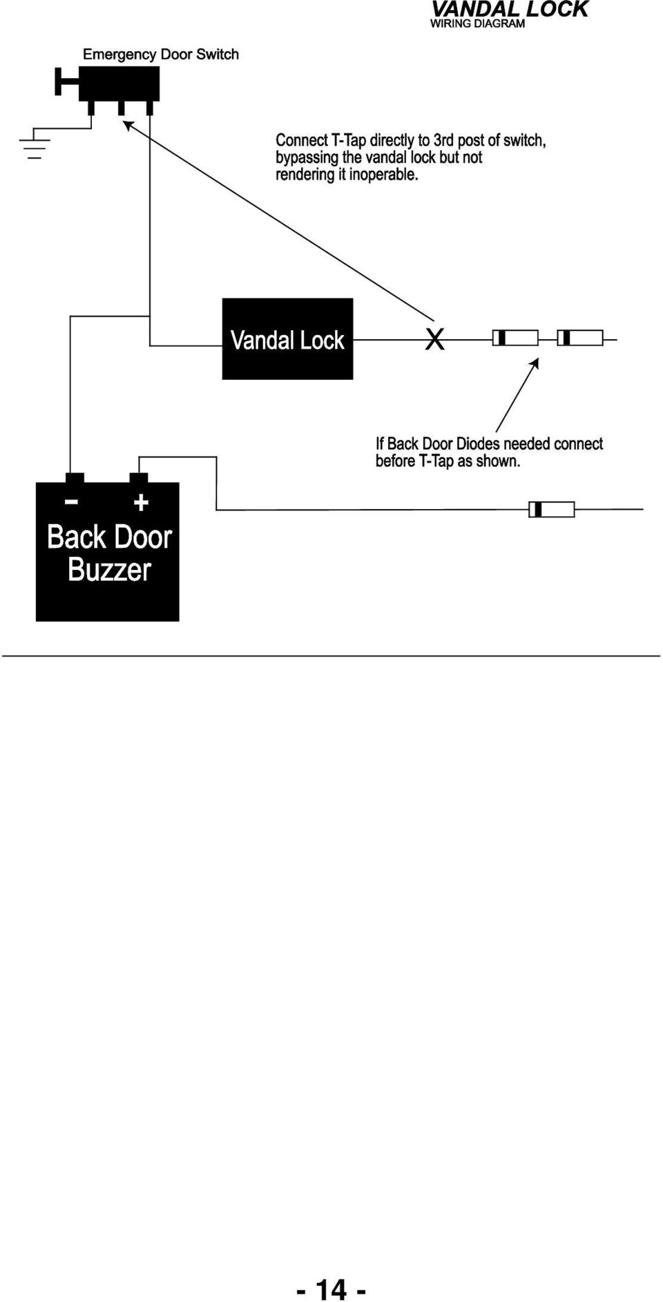
6 You Need to Know This First! What is a diode? A diode is an electrical one-way valve. Current will flow in one direction only. This means that there is a polarity to observe when using them. Think of current as flowing from the positive terminal of the battery, through a load to ground. A diode can be placed in series with the circuit anywhere, as long as current comes in the lead without the grey stripe and leaves through the lead with the grey stripe. The diode will then allow current to flow in the proper direction only. It will stop any current from flowing backwards. The diodes included with the Child Reminder have a maximum current rating of 1 Amp. Why are diodes necessary? The Child Reminder is a microprocessor controlled system. School bus body manufacturers still use mechanical buzzers. When the CR2A microprocessor attempts to sense resistance and voltage levels in the rear door circuit, current can flow backwards through the buzzers causing incorrect readings if diodes are not used. In general, diodes help create a trouble-free system by isolating various circuits from each other. Buzzer Isolation Diode(s) IMPORTANT!!! A diode MUST be installed in series with each wire feeding accessory power to each emergency exit buzzer. Install the diode(s) so that the terminal WITH the grey stripe faces the buzzer. This will keep current from running backwards through the buzzer(s). Do not skip this step! - 6 -

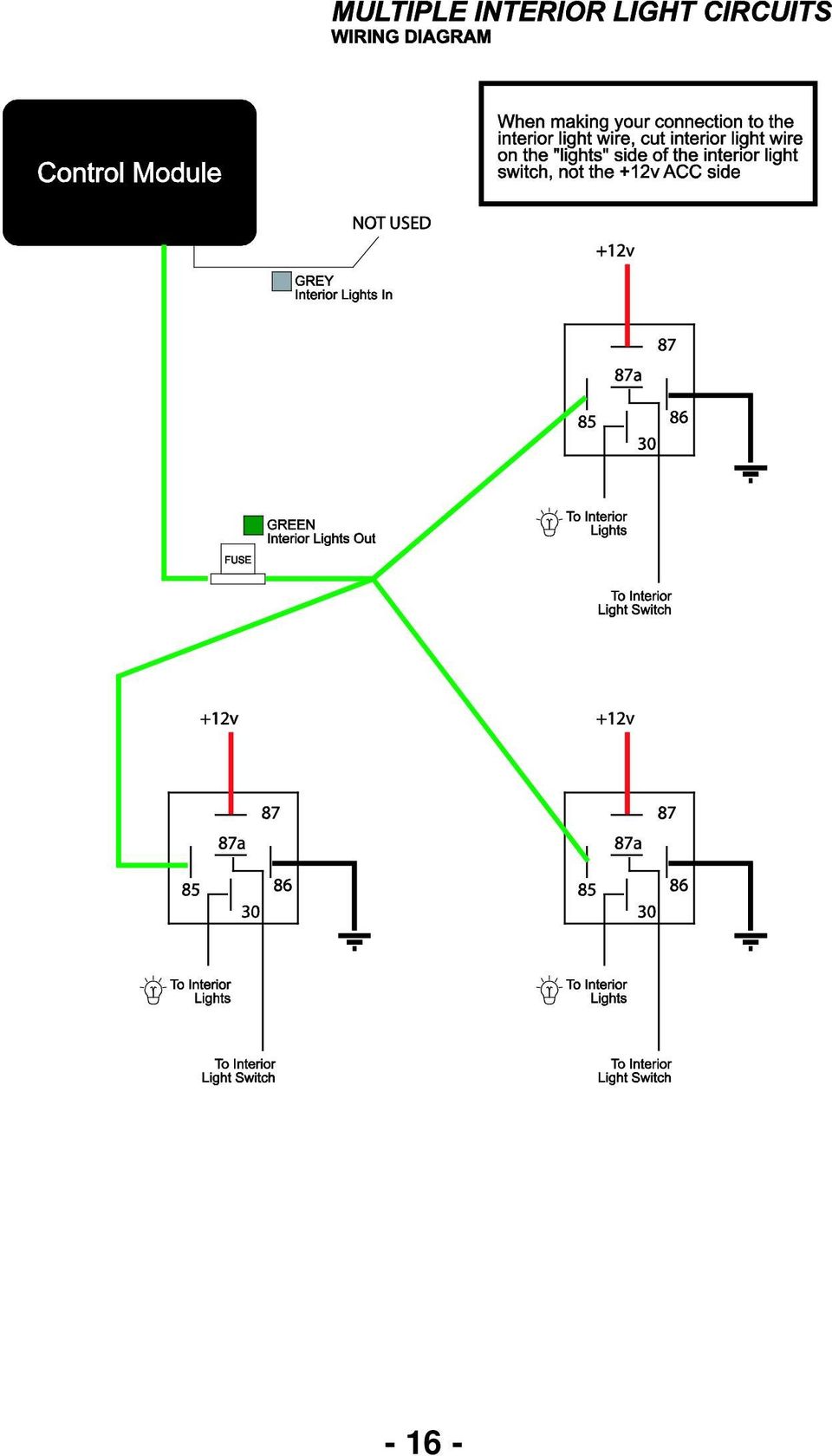
7 Wiring Harness Connections RED (Power) Connect to constant + 12V. DO NOT CUT OUT THE FUSE. This fuse is necessary to prevent possible damage to both the Child Reminder and the school bus. BLACK (Ground) Connect to ground. YELLOW (Accessory Power) Connect to accessory power. This wire must receive + 12V when the ignition key is in the ON or Accessory positions. GREEN and GREY (Interior Lights In/Out) Locate the wire running from the interior light switch to the interior lights. Cut it. Connect the green wire to the wire running TOWARDS the interior lights. This wire provides + 12V power (10 Amp maximum) to turn on the interior lights. Connect the grey wire to the wire coming from the interior light switch. DO NOT CUT OUT THE FUSE. This fuse is necessary to prevent possible damage to both the CR2A and the school bus. BLUE (Horn Output) Connect to the vehicle horn relay or directly to the horn. The blue wire will output either + 12V or ground signals (10 Amp maximum) to energize the vehicle horn relay. For information on locating the horn relay wire in the vehicles, see the section Locating The Horn Wire And Identifying It s Polarity. Also see the section How The Horn Circuit Works. RED/WHITE (Horn Polarity) If a + 12V signal is required to activate the vehicle horn, connect this wire to constant + 12V. If a ground signal is required to activate the vehicle horn (most common type), connect this wire to ground. For information on determining the horn wire polarity, see the section Locating The Horn Wire And Identifying It s Polarity. DO NOT CUT OUT THE FUSE. The fuse is necessary to prevent possible damage to both the Child Reminder and the school bus
 to turn on the interior lights. Connect the grey wire to the wire coming from the interior light switch. DO NOT CUT OUT THE FUSE.")
8 ORANGE (Arming Wire) When this wire receives + 12V (and accessory power is on), it will arm the system meaning the bus must be checked upon shutdown. If you want the system to arm when the overhead warning lights have been used, connect to the warning light master switch or the stop arm output on the warning light flasher. If you wish to have the system arm every time the vehicle is started, connect the orange wire to accessory power. Some customers have connected this wire to the brake light switch (requires bus to be checked if it is MOVED). GREEN/VIOLET (Positive Door Input) For standard large buses this wire is usually not used. This wire is only required if there are any positive type door switches (some mini bus driver doors). Connect to door switches that read + 12V when the door is open. Leave disconnected if no positive door switches are present. If more than one positive door switch must be monitored, see the section Monitoring Multiple Door Switches. VIOLET (Negative (Grounding) Door Input) Connect to service door switches that go to ground when the door is open. Leave disconnected if no ground type door switches are present. A good place to find the door switch signal is on the 4/8 way overhead warning light flasher. Connect to either the Flash reds whenever door is open terminal or the Flash reds only after ambers terminal. One of them will be connected to the bus door switch already. You can piggy back the Child Reminder door switch input at this point. If other components use the door switch (air solenoid for stop arm, relays, etc.), you may need to install a diode in series with the other component(s). If the system sounds the horn immediately upon shutdown of accessory power (without opening the service / entrance door), other components in the bus are interfering with the system. Determining Rear Door Wiring Configuration The white wire is used if the bus has a dedicated wire (side window exits and roof hatches on a separate wire) that runs from the front buzzer to the rear door switch. Most buses are wired this way. The Black / Grey wire is used if the rear door switch shares a wire with other emergency exits (ex. Blue Bird). To determine if the rear door switch has its own wire, turn on the accessory power and open the rear door. The front buzzer should sound. Begin removing wires from the negative post on the front buzzer. When it stops buzzing, you have found the rear door switch wire. Reconnect all other wires, leaving the rear door switch wire disconnected. Open the other emergency exits one by one. If they all still activate the buzzer, the rear door switch has it s own wire. If any of the other exits can only activate the buzzer if this wire is connected, they share the wire with the rear door and the diode sniffer wire (Black / Grey) must be used instead of the white wire. Thomas and International/Amtran have dedicated wires. Blue Birds do not
.")
9 WHITE (Dedicated Rear Door Wire) Deactivation To use the rear door, disconnect the dedicated rear door switch wire from the negative post on the front buzzer (located near the driver s seat) and feed it directly to the white wire on the Child Reminder. Install a diode (grey stripe towards white wire) between the white wire and the negative post on the buzzer. See the wiring diagram for clarification. If a momentary type push button is installed at the back of the bus with a dedicated wire running to it, connect the white wire to the push button. Connect the other side of the push button to ground. Or BLACK / GREY (Diode Sniffer for Shared Read Door Wire) Deactivation This wire is to be used when other emergency exits share the wire running from the rear door switch up to the front buzzer. Connect to the negative post of the rear door warning buzzer located near the driver s seat. Leave the rear door switch wire connected to the buzzer. Connect 2 diodes in series with the rear door switch at the back of the bus. The Child Reminder will scan ALL of the emergency exit switches and look for the one with these diodes attached. A momentary push button switch can be used instead of the rear door switch by connecting one side of the button to the rear door switch wire. Connect the other side through 2 diodes to ground. See the wiring diagram for clarification

10 How the Horn Circuit Works To activate the horn, The Child Reminder connects the Red/White wire to the Blue wire internally through the contacts of a 10 Amp relay. Whatever connection (+12V or ground) is made to the Red/White wire will be fed out through the Blue wire when the system attempts to turn on the horn. This feature eases installation and eliminates the need for external relays and additional wiring. Locating the Horn Wire and Identifying its Polarity The horn wire can almost always be found at the base of the steering column. Connect the alligator clip of a test light to ground. Probe the wire you believe carries the horn signal with the test light. If the horn activates immediately upon probing, you have found the correct wire. In addition, you can also conclude that the horn is activated by a ground signal. Test lights draw enough current to activate many ground triggered horn relays. If you find a wire that lights up the test light immediately (may only be a dim light), and turns the light off when the horn is activated, you have most likely found the correct wire and can conclude that the horn is activated by a ground signal. If you find a wire that lights up the test light when the horn is activated, you have most likely found the correct wire and can be fairly certain that it requires + 12V to activate the horn. Identifying the +/ - Posts on the Buzzer Connect the alligator clip of a test light to ground. Turn on the ignition. Probe one terminal of the buzzer. Observe the brightness of the test light and listen carefully to the buzzer. Probe the other side of the buzzer. Observe the brightness of the test light and listen carefully to the buzzer. The positive (+) terminal of the buzzer should give a noticeably brighter test light reading than the negative (-) terminal of the buzzer. In addition, the buzzer will attempt to activate when probing the negative (-) terminal. Tapping the test light repeatedly to the terminal will help you hear the buzzer attempting to sound

11 Testing System Operation 1. Start the vehicle. Close all doors. 2. Turn the ignition key to the OFF position 3. Confirm that the interior lights did not illuminate. 4. Start the vehicle. 5. Activate the warning lights. 6. Turn off the warning lights. 7. Turn the ignition key to the OFF position 8. Confirm illumination of interior lights and LED. 9. Open any door except rear door. 10. Confirm vehicle horn honking 11. Turn ignition key to Accessory Power position. 12. Confirm silencing of the vehicle s horn. 13. Close all doors. 14. Turn ignition key to OFF position. 15. Confirm illumination of interior lights and LED. 16. Open any emergency exit except rear door. 17. Confirm interior lights DO NOT flash. 18. Close all emergency exits. 19. Open rear door. 20. Confirm 2 flashes of interior lights. 21. Wait approximately 20 to 30 seconds. 22. Confirm shut off of interior lights and LED. Notes: Steps 9 through 15 should be followed for each door to confirm that the bus driver cannot exit any doors without triggering the alarm. Steps 16 and 17 should be followed for each emergency exit to confirm that the bus driver cannot deactivate the system with an emergency exit other than the rear door. If you are testing a Child Reminder Model B go to page 16. If you are testing a Child Reminder Day Care Model go to page

12 Troubleshooting Guide Problem Corrective Actions System does not arm upon shut down of accessory power. Check the fuse on the RED wire. RED should be +12V constant. YELLOW should be +12V ACC, and ORANGE must receive +12V for at least 0.6 seconds to arm the system. Typically ORANGE is connected to the warning light circuit or to ACC. Did you remember to turn on the accessory power AND the warning lights (or whatever system you connected the ORANGE wire to) to arm the system? Interior lights do not activate, but LED turns on. System won t deactivate when I crack the rear door handle open. I am using the diode sniffer wire. System deactivates itself immediately upon shut down of the accessory power. (Interior lights flash twice, then go out 20 seconds later). Horn activates immediately upon shut down of the accessory power. I am using the violet wire for my entrance door input and have verified that it is piggy backed on door input connector on the warning light flasher. Horn does not activate when I turn off accessory power and open a door, but I can hear a relay inside the control module clicking on and off. Horn does not activate when I turn off accessory power and open a door, and I do not hear any relays clicking inside the control module. Check connections on GREY and GREEN wire. GREEN wire must go towards interior lights. Check fuse on GREEN wire. Make sure all emergency exits are closed. The system can t find the diodes if another exit is open. Check connection on BLACK/GREY wire. Is it on the negative terminal of the buzzer? Did you put a diode in series with each buzzer to stop reverse current flow? Make sure 2 diodes are properly installed at rear door switch. Buzzers are not isolated properly and current is running backwards through them. Check installation of diode(s) on accessory power feeds to buzzer(s). The most common cause is another component (stop arm air solenoid, crossing arm, relay coil, etc.) using the same entrance door switch without proper isolation. Check resistance to ground of door switch wire with Child Reminder unplugged and ignition key off. If it is below 5,000 ohms, look for a component (other than the warning light flasher) that may be sharing the switch. Install a diode in series with the component causing the low resistance reading. Check connection on BLUE wire. Verify that you have connected it to the vehicle horn relay wire. Log on to website to find the wire. Check connection on RED/WHITE wire. Verify that you connected it to +12V constant or to ground, depending on vehicle horn signal polarity. Most buses are grounding type. Check fuse on RED/WHITE wire. Check door trigger connections. If used, the GREEN/VIOLET wire should read 0V when the door is closed, and +12V when it is open. If used, the VIOLET wire should read +12V when the door is closed, and 0V when it is open

13 - 13 -

14 - 14 -
15 - 15 -

16 - 16 -
17 Child Reminder: Model B Part Number: CR2B System arms with the warning lights as well as self arms 10 minutes after the bus has been running with the door closed. The system can only be disarmed with the key in the off position. When the bus shuts down the interior lights will go on for added view of the bus and an LED will illuminate on the dash. The driver is required to go to the back of the bus and lift the door handle to disarm. A push button is optional. When the driver disarms the system, the lights will flash to confirm that the system is disarmed and will stay on for the next 60 seconds, for added view when returning to the front of the bus. The driver is now free to exit the bus. If this procedure is not followed, the horn will honk immediately when the driver tries to exit the bus. The driver will then be required to put the key back in the ignition in the on position to stop the horn from honking and close the door and start the process over. Added Features 1. Self Arming Arms after 10 minutes of the bus running with the door closed. This will protect field trips when warning lights are not used. 2. Diagnostic Check- When performing the pre-trip inspection, the driver will open an close the service door quickly twice and the horn will honk to confirm the Child Reminder is functioning properly. If the horn does not honk, the system should be checked by the mechanics. 3. Courtesy Lighting- The interior lights will illuminate when the door is opened. It is on a two minute timer to protect against a dead battery should the door blow open in the middle of the night. Part Number: CR2B-FL- Florida Version - System arms with the warning lights as well as self arms 10 minutes after the bus has been running with the door closed. The system can only be disarmed in the off position. When the bus shuts down the interior lights will go on for added view of the bus and an LED will illuminate on the dash. The driver is required to go to the back of the bus and lift the door handle to disarm. A push button is optional. The driver has 60 seconds in which to disarm or the horn will start to honk. When the driver disarms the system, the lights will flash to confirm that the system is disarmed and will stay on for the next 60 seconds, for added view when returning to the front of the bus. The driver is now free to exit the bus. If this procedure is not followed, the horn will honk immediately when the driver tries to exit the bus. The driver will then be required to put the key back in the ignition in the on position to stop the horn from honking and close the door and start the process over. Added Features 1. Self Arming - After 10 minutes of the bus running with the door closed. This will protect field trips when warning lights are not used. 2. Courtesy Lighting- The interior lights will illuminate when the door is opened. It is on a two minute timer to protect against a dead battery should the door blow open in the middle of the night

18 Wiring Changes: There are three different ways to wire the CR2B and CR2B-FL depending how you would like the alarm to function. 1. If you want the system to arm every time the key is turned on connect the orange wire to +12V accessory. 2. If you want the system to arm after the bus runs for 10 minutes or when the warning lights are used, connect the orange wire to the stop arm output of the warning light flasher. 3. If you want the system to only arm after the bus has been running for 10 minutes, DO NOT connect the orange wire. Testing System Operation: CR2B 1. Open service door and confirm illumination of interior lights 2. Wait 2 minutes and confirm shut off of interior lights 3. Start the vehicle. Close all doors 4. Turn the ignition key to the OFF position 5. Confirm that the interior lights did not illuminate 6. Start the vehicle. Let it run for at least 10 minutes 7. Turn the ignition key to the OFF position 8. Confirm the interior lights and LED have illuminated 9. Open service door or driver s door (if present) 10. Confirm vehicle horn honking 11. Turn ignition key to ON position 12. Confirm silencing of the vehicle s horn 13. Close ALL doors 14. Turn ignition key to OFF position 15. Open any emergency exit except rear door 16. Confirm interior lights DO NOT flash 17. Close ALL emergency exits 18. Open rear door or push deactivator button (if installed) 19. Confirm 2 flashes of the interior lights 20. Wait approximately seconds 21. Confirm shut off of interior lights and LED If you used 1 or 2 in the wiring changes also follow these steps 22. Start the vehicle. Close all doors 23. Activate the warning lights. 24. Turn off the warning lights. 25. Turn the ignition key to the OFF position 26. Repeat Steps 8 to Open and close front service door twice quickly 28. Confirm double honk from vehicles horn CR2B-FL substitute these above 25. Turn ignition key to OFF position, wait approximately 60 seconds 26. Confirm vehicle horn honking 27. Repeat Steps 8 to

19 Child Reminder: Day Care Part Number: CR2ADCREVB For Daycare vans. Used in vehicles that do not have access to the back from inside the vehicle. The unit will arm when the ignition is turned on. When the van shuts down the interior lights will illuminate and the driver has a 60 second time limit to get out of the vehicle and around to the side door to reach in and disarm the system by pushing a button. If the unit is not disarmed within 60 seconds, the horn will start honking until the button is pushed to disarm. The lights will flash to confirm deactivation. Wiring Changes: The system must arm every time the key is turned on. To do this, connect the orange wire to +12V accessory. Interior Lights (Green and Grey) most often are not used. If you desire these to function please call and ask to speak to Technical Support. Door Trigger wires (Violet and Green/Violet) are most often times not used unless you wish the driver to remain inside and travel through the vehicle to the rear to depress the deactivator button. In some cases such as Ford, GMC, Chevy, and Dodge 15 passenger Vans this is not desirable as the spacing is very tight and was not designed for this purpose. Push Button is connected to the white wire. You will need to extend this wire to reach the rear of the vehicle. In vans, install the push button in the middle between the children s loading door and the back double doors. In School Bus type vehicles, install the button at the rear wall above the rear windows. Testing System Operation: 1. Start the vehicle. Close all doors 2. Turn the ignition key to the OFF position 3. Confirm the interior lights and LED have illuminated 4. Wait approximately 60 seconds 5. Confirm vehicle horn honking 6. Turn ignition key to ON position 7. Turn ignition key to OFF position 8. Confirm the interior lights and LED have illuminated 9. Deactivate system by pushing the button 10. Confirm 2 flashes of the interior lights 11. Confirm shut off of interior lights and LED
 most often are not used.")
20 Notes:

21 This box contains: Qty Description 1 Control module 1 Wiring harness 1 LED with wire and plug 1 NOTICE sticker 6 1 Amp diodes Tools you will need to perform this installation: Cordless Drill Crimpers and Wire Strippers 21/64 LED Drill Bit Test Light and Volt/Ohm Meter Connection method Mar, Quick Connects, Solder Technical Support: Other innovative products from CRS Electronics include: G2 Fusion LED Warning Lights Red, Super Red and Amber 7 LED Brake/Tail and Signal Lights 4 LED Brake/Tail and Signal Lights 4 LED Clear Backup Light 4 LED Brake/Tail with LED License Plate Light Assorted LED Marker Lights Headlight Flasher
1R / 4-BUTTON SERIES
 Button 1 1R / 4-BUTTON SERIES VEHICLE SECURITY SYSTEM Standard Features: Two 4-Button Remote Transmitters Status indicator (LED) Valet / override switch Multi-tone siren Dual stage impact detector Remote
WIRING HARNESS FOR AS635P4. BLUE PLUG RED, BLUE, BLACK, WHITE - Plug in dual stage sensor harness
 WIRING HARNESS FOR AS635P4 ANTENNA NOT USED 5 PIN WHITE PLUG 2 PIN WHITE PLUG GREEN - PARKING BRAKE INPUT (-) BLUE - NOT USED 3 PIN BLUE PLUG RED, BLUE, BLACK, WHITE - Plug in dual stage sensor harness
INSTALLATION MANUAL 3RP / 5RP 4-BUTTON SERIES VEHICLE SECURITY SYSTEMS
 3RP / 5RP 4-BUTTON SERIES VEHICLE SECURITY SYSTEMS INSTALLATION MANUAL Before you begin the installation Read the INSTRUCTIONS! Always use a multi-meter when verifying vehicle wiring. Before mounting the
Multi Function, User Configurable Remote Vehicle Security System with 4 Button Replaceable Membrane Remote Transmitter
 MODEL PRO-9744 INSTALLATION MANUAL Multi Function, User Configurable Remote Vehicle Security System with 4 Button Replaceable Membrane Remote Transmitter This System Allows The Transmitter Buttons To Be
PRO PLM Installation Instructions
 PRO PLM Installation Instructions PROFESSIONAL INSTALLATION STRONGLY RECOMMENDED Installation Precautions: Roll down window to avoid locking keys in vehicle during installation Avoid mounting components
VEHICLE THEFT/SECURITY SYSTEMS
 DN VEHICLE THEFT/SECURITY SYSTEMS 8Q - 1 VEHICLE THEFT/SECURITY SYSTEMS TABLE OF CONTENTS page GENERAL INFORMATION INTRODUCTION...1 VEHICLE THEFT SECURITY SYSTEM....1 ENABLING...1 ARMING...1 DISARMING...2
INSTALLATION GUIDE OWNER S GUIDE
 INSTALLATION GUIDE OWNER S GUIDE KEYLESS ENTRY MODELS KE100 / KE150 / 1702 CONTENTS System Features... 1 System Components... 1 Technical Assistance... 1 Before You Begin... 1 Precautions... 1-2 Making
K9 Heat Alarm Owners Manual HA-1520
 K9 Heat Alarm Owners Manual HA-1520 Your K9 Heat Alarm is a state of the art product designed and developed by ACEK9.COM a division of Radiotronics, Inc. It is a unique blend of positive features taken
KEYLESS ENTRY UPGRADE SECURITY SYSTEM for 2004 TOYOTA HIGHLANDER
 KEYLESS ENTRY UPGRADE SECURITY SYSTEM for 2004 TOYOTA HIGHLANDER DEALER SERVICE AND INSTALLATION MANUAL KIT NO. 00016-30915 Contents PARTS LIST... 2 PARTS ILLUSTRATIONS... 2 VEHICLE PREPARATION... 3 INSTALLING
i ChatterBox! Motorcycle Security
 i Before you Start the Installation * Please read this manual to become familiar with the requirements necessary to complete the installation. * Use a high quality multi-meter to test all wires before
INSTALLATION GUIDE OWNER S GUIDE
 INSTALLATION GUIDE OWNER S GUIDE SECURITY SYSTEM PRO-SERIES 5002 CONTENTS System Features... 1-2 System Components... 2 Technical Assistance... 2 Before You Begin... 2 Precautions... 2-3 Making Connections...
How To Control A Car Alarm On A Car With A Remote Control System
 MODEL CA100 REMOTE CONTROL AUTO ALARM SYSTEM INSTALLATION & OPERATION INSTRUCTIONS WIRING DIAGRAM Black Antenna Wire 6 Pin 6 Pin Mini Connector Valet Switch Blue LED Indicator Blue Wire: (-) 200mA Unlock
2003/2004/2005 TOYOTA COROLLA
 2003/2004/2005 TOYOTA COROLLA KEYLESS ENTRY UPGRADE SECURITY SYSTEM INSTALLATION INSTRUCTIONS KIT NO. 00016-30120 SPECIAL NOTE: Installation Sequences After TMS and Safety mandated preparatory steps have
SP-100 REMOTE CONTROL ALARM SYSTEM INSTALLATION & OPERATING INSTRUCTIONS INTRODUCTION
 SP-100 REMOTE CONTROL ALARM SYSTEM INSTALLATION & OPERATING INSTRUCTIONS INTRODUCTION CONGRATULATIONS on your choice of a Security Plus Remote Alarm System by Crimestopper Security Products Inc. This booklet
Button 1 Button 2. Button 3 Button 4. Programmed Remote Transmitter. Button Function Condition
 WWW.STELLAR.COM ST9000 SECURITY SYSTEM Button Function Condition 1 a. Arm and lock doors b. Car finder with sound c. Temporary stop alarm from sounding d. Remote lock doors 1 for 2 sec. Panic Anytime a.
ANTI-THEFT SYSTEM. 1995 Volvo 850 DESCRIPTION & OPERATION BASIC ALARM. 1995-96 ACCESSORIES & EQUIPMENT Volvo Anti-Theft Systems
 ANTI-THEFT SYSTEM 1995 Volvo 850 1995-96 ACCESSORIES & EQUIPMENT Volvo Anti-Theft Systems 850 DESCRIPTION & OPERATION WARNING: Deactivate air bag system before performing any service operation. For 1995
PUSH BUTTON START INSTALLATION MANUAL
 PUSH BUTTON START INSTALLATION MANUAL ALTHOUGH THIS PRODUCT HAS BEEN THOROUGHLY TESTED KPIERSON TECHNOLOGIES ASSUMES NO RESPONSIBILITY FOR ANY DAMAGE THAT MAY RESULT BY THE INSTALLATION OF THIS PRODUCT.
Copyright 2002-2004 Triple S Customs
 CHEVROLET SILVERADO 1988-2005 VEHICLE WIRING Copyright 2002-2004 Triple S Customs WIRING INFORMATION: 1988 Chevy Silverado Full-Size 2- POWER DOOR LOCK (5-wire reverse polarity) POWER DOOR UNLOCK (5-wire
HONDA ACCORD 1985-2005
 HONDA ACCORD 1985-2005 VEHICLE WIRING Copyright 2002-2004 Triple S Customs WIRING INFORMATION: 1985 Honda Accord WIRE WIRE COLOR WIRE LOCATION 12V CONSTANT WHITE or WHITE/BLACK Ignition Harness STARTER
LAND ROVER MANUAL CONTENTS APPLICATIONS GENERAL OPERATION SPECIAL FUNCTIONS REMOTE CONTROL PROGRAMMING
 LAND ROVER LAND ROVER MANUAL CONTENTS APPLICATIONS GENERAL OPERATION SPECIAL FUNCTIONS REMOTE CONTROL PROGRAMMING APPLICATIONS VEHICLE SYSTEM YEAR CABLE CLASSIC RANGE ROVER 10AS 95 ON ADC110-B DEFENDER
535T Window Automation System
 535T Window Automation System Installation Guide NOTE: This product is intended for installation by a professional installer only! Any attempt to install this product by any person other than a trained
Part Number: 250-1859
 General Applicability 2010 Honda Insight 07- Kia Optima / Forte / Rondo/ 10- Sedona / 12 Soul 10- Hyundai Tucson / Elantra Touring ETC 2012 Accent / Elantra/ Genesis Recommended Tools Safety Tools Gloves,
Left Hand Limit Switch. Housing. Left Hand. Connections. Motor Connector BROWN PURPLE GRAY BLACK DARK BLUE BLACK BROWN BROWN LIGHT BLUE.
 LIGHT BLUE GRAY PURPLE Circuit Breaker Intput Circuit Breaker Output #1 Relay Left Hand Limit Switch Housing Left Hand Motor Connector Right Hand Limit Switch on Radiator Support Right Hand Limit Switch
INSTRUCTIONS FOR THE INSTALLATION AND OPERATION OF ACTIVATOR II
 INSTRUCTIONS FOR THE INSTALLATION AND OPERATION OF ACTIVATOR II ELECTRONIC TRAILER BRAKE CONTROL 5500 FOR 2, 4, 6 & 8 BRAKE SYSTEMS IMPORTANT: READ AND FOLLOW THESE INSTRUCTIONS CAREFULLY. KEEP THESE INSTRUCTIONS
www.sebury.com.cn Digital Keypad Use s Manual
 K3 K4 www.sebury.com.cn Digital Keypad Use s Manual Contents Introduction Introduction Specifications Intramural Interface Circuit 3 Mounting 3 Wiring 5 Power UP 7 Engineer Programming Mode 7 The K3/K4
Welcome to this training presentation on the Child Safety Alarm law.
 Welcome to this training presentation on the Child Safety Alarm law. 1 Objectives: Toprovide a brief background of the Child Safety Alarm Bill and what the law entails. To identify examples of child safety
ILISC515-A Shift Interlock (Manual Lift Door) 2015 Ford Transit, 3.7L and 3.5L
 2015 Ford Transit, 3.7L and 3.5L") An ISO 9001:2008 Registered Company ILISC515-A Shift Interlock (Manual Lift Door) 2015 Ford Transit, 3.7L and 3.5L Introduction The ILISC515-A is a microprocessor driven system for controlling wheelchair
An ISO 9001:2008 Registered Company ILISC515-A Shift Interlock (Manual Lift Door) 2015 Ford Transit, 3.7L and 3.5L Introduction The ILISC515-A is a microprocessor driven system for controlling wheelchair
Installation Instructions
 Installation Instructions for EVS II Security and Keyless Entry Systems Note: It is recommended that this installation take place prior to rustproofing. The individual delivering the vehicle should review
INSTALLATION MANUAL VEHICLE SECURITY SYSTEM CE-SS200
 INSTALLATION MANUAL VEHICLE SECURITY SYSTEM CE-SS200 FUSION CULTURE TABLE OF CONTENTS There s no point doing something if no one notices. We ve always believed the way to make things happen is by getting
Model AM2. Installation Guide
 Model AM2 Installation Guide NOTE: This product is intended for installation by a professional installer only! Any attempt to install this product by any person other than a trained professional may result
VEHICLE SECURITY SYSTEM G25/G20
 VEHICLE SECURITY SYSTEM G25/G20 Limited Lifetime Warranty This vehicle security system is warranted to the original purchaser, to be free from defects in material and workmanship. The manufacturer will
SECURITY SYSTEM ADP-CAN
 INSTALLATION INSTRUCTION SECURITY SYSTEM ADP-CAN Introduction Motorcar security system ADP-CAN is for motorcars provided with CAN net. It is for the work with the motorcar factory security systems or remote
INSTALLATION GUIDE. www.security.soundstream.com FCC ID NOTICE
 AL.1 AUTO SECURITY SYSTEM INSTALLATION GUIDE www.security.soundstream.com FCC ID NOTICE This device complies with Part 15 of the FCC rules. Operation is subject to the following conditions: 1. This device
Security and Remote Start Installation Guide for models: CA 6150 CA 6550
 PROFESSIONAL SERIES Security and Remote Start Installation Guide for models: CA 6150 CA 6550 2009 Audiovox Electronics Corporation. All rights reserved. 1 Table of Contents Before You Begin... 4 Wire Connection
Copyright 2002-2004 Triple S Customs
 JEEP GRAND CHEROKEE 1992-2006 VEHICLE WIRING Copyright 2002-2004 Triple S Customs WIRING INFORMATION: 1992 Jeep Grand Cherokee 12V CONSTANT WIRE PINK/BLACK or RED/WHITE Steering Column STARTER WIRE YELLOW/BLUE
e-ask electronic Access Security Keyless-entry
 e-ask electronic Access Security Keyless-entry e-fob Keyless-entry entry System Full-Function Function Installation Manual FCC ID: TV2EFOB1 (UM20 ~ 22793-02) Table of Contents Introduction... 1 e-fob Operation
Car Alarm Series 2 B 2 Buttons
 Car Alarm Series 2 B 2 Buttons G22 SE (External - Shock Sensor) Version 3 Software 67 Plus www.geniuscaralarm.com 21 CAR ALARM GENIUS Series 2B 2 Buttons - G22 Se (External Shock Sensor) Module controlled
SECTION 1-5 OPERATION OF INSTRUMENTS AND CONTROLS 06.0.711. Lights, Wipers and Defogger
 OPERATION OF INSTRUMENTS AND CONTROLS Lights, Wipers and Defogger SECTION 1-5 Headlights and turn signals................................... 76 Emergency flashers..........................................
2004 Directed Electronics, Inc. Vista, CA N426V 07-04
 350HV Installation Guide NOTE: This product is intended for installation by a professional installer only! Any attempt to install this product by any person other than a trained professional may result
PATENTED: www.voxxintl.com/company/patents
 Model PRO9776C Installation Manual Vehicle Security System Table Of Contents: with Remote Start Before You Begin Page 2 Wire Harnesses Quick View Page 3-4 Installation of the Major Components Page 5 Wiring
PATENTED: www.voxxintl.com/company/patents
 Model APS-997C Installation Manual 2 Way LCD Vehicle Security and Table Of Contents: Remote Start System Before You Begin Page 2 Wire Harnesses Quick View Page 3 and 4 Installation Of The Major Components
Vehicle Alarm System With Channel 2 Auxiliary Output Installation Instructions
 Model PRO 9842 Installation Manual Vehicle Alarm System With Channel 2 Auxiliary Output Installation Instructions This Unit Is Intended For Installation In Vehicles With 12 Volt Negative Ground Electrical
INSTALLATION GUIDE. Card Reader & Controller with KIM Swipe Reader for Solitaire 850 / 950 / 850L Learnlok PK2930
 INSTALLATION GUIDE Card Reader & Controller with KIM Swipe Reader for Solitaire 850 / 950 / 850L Learnlok PK2930 Card Reader and Controller Model 3.5 with KIM Swipe Reader Table of Contents 1. Features..................................
ENERGY SMART TROUBLESHOOTING GUIDE TABLE OF CONTENTS:
 ENERGY SMART TROUBLESHOOTING GUIDE TABLE OF CONTENTS: COMPONENTS/BOARD LAYOUT... 2 HOT WATER... 3 1 FLASH (GREEN DIAGSTIC LIGHT)... 4 2 FLASHES (GREEN DIAGSTIC LIGHT)... 5 3 FLASHES (GREEN DIAGSTIC LIGHT)...
Electrical Systems - IQAN Digital Control System. IQAN Control System Components... 5.1.3
 Section 5.1 Electrical Systems - IQAN Digital Control System IQAN Control System Components........................... 5.1.3 IQAN Operational Description: At Machine Startup.....................................
SFC-200 SERIES LCD FIRE ALARM PANEL
 SFC-200 SERIES LCD FIRE ALARM PANEL User Guide LT-954SUM SFC-200 Series LCD Version User Guide Contents Introduction... 1 About this Manual... 1 Technical Support... 1 Main Display... 1 The Buzzer and
Networkfleet 3500 Product Line Installation Guide
 Networkfleet 3500 Product Line Installation Guide Light/Medium Duty (L3500) Heavy Duty (H3500) Universal (U3500) www.networkcar.com/fleet Customer Care: (866) 227-7323 [email protected] Table
Mazda CX7 2007-09 99-7508
 INSTALLATION INSTRUCTIONS FOR PART 99-7508 APPLICATIONS Mazda CX7 2007-09 99-7508 KIT FEATURES DIN Radio Provision with Pocket ISO Mount Radio Provision with Pocket Double DIN Mount Radio Provision Stacked
MotorCycle Alarm by DEF COM 3 INSTALLATION MANUAL 80 C
 DEF COM 3 INSTALLATI MANUAL MotorCycle Alarm by IMMOBILISER (FAIL SAFE SYSTEM) Positive Logic (the relay switches over when the central unit is disarmed and ignition +15 is present.) Fig.2 Fig.3 SUPPLEMTARY
LPE Handheld Programmer
 Lingenfelter Performance Engineering 1557 Winchester Road Decatur, IN 46733 Tel.: 260-724-2552 Fax: 260-724-8761 www.lingenfelter.com LPE Handheld Programmer Operating Instructions LPE PROGRAMMER OVERVIEW
MAGICAR M870AS. Car alarm with two-way remote and remote - start system Installation guide
 MAGICAR M870AS Car alarm with two-way remote and remote - start system Installation guide EN English TABLE OF CONTENTS I. INTRODUCTION...4 II. PLACING...4 III. ADDITIONAL RELAY 12V CONNECTION...1 IV. WIRING
OPERATING INSTRUCTIONS SECURITY SYSTEM KIT NO.: 08E51-EP4-101. 2004 American Honda Motor Co., Inc. - All Rights Reserved. 1
 OPERATING INSTRUCTIONS SECURITY SYSTEM KIT NO.: 8E5-EP4-24 American Honda Motor Co., Inc. - All Rights Reserved. Contents Introduction... 3 Emergency Disarming During Alarming... 4 During the Entry Delay
FUNCTIONS FUNCTIONS PROGRAMMABLE THROUGH THE TRANSMITTER DESCRIPTION
 DESCRIPTION The systems 7463 and 7462 are modular systems which consists of an alarm unit and one audible external siren. These alarm systems can be installed on vehicles with 12V battery with negative
BODY ELECTRICAL MAZDA
 BODY ELECTRICAL ASSIGNMENT WORKSHEETS Version 1.3 MAZDA ELECTRICAL WIRING DIAGRAM WORKBOOK http://www.autoshop101.com Developed by Kevin R. Sullivan All rights reserved. MAZDA Table of Contents Wiring
INSTALLATION INSTRUCTIONS
 Rear Vision System Tailgate Handle Camera Mirror Display 2004-2014 Ford F-150 and 2008-2015 Ford Super Duty (Kit part numbers 9002-9521) Kit Contents: Mirror Tailgate Handle with camera and harness Interior
ELECTRICAL WIRING (R.H. DRIVE VEHICLES)
") C-1 ELECTRICAL WIRING (R.H. DRIVE VEHICLES) CONTENTS GENERAL.......................... 3 WIRING HARNESS CONFIGURATION DIAGRAMS......................... 4 ENGINE COMPARTMENT................ 4 DASH PANEL...........................
C-1 ELECTRICAL WIRING (R.H. DRIVE VEHICLES) CONTENTS GENERAL.......................... 3 WIRING HARNESS CONFIGURATION DIAGRAMS......................... 4 ENGINE COMPARTMENT................ 4 DASH PANEL...........................
INSTRUMENT PANEL. 1995 Volvo 850 DESCRIPTION & OPERATION. 1995-96 ACCESSORIES & EQUIPMENT Volvo Instrument Panels
 INSTRUMENT PANEL 1995 Volvo 850 1995-96 ACCESSORIES & EQUIPMENT Volvo Instrument Panels 850 WARNING: When working around steering column and before performing repairs, disconnect and shield battery ground
INSTALLATION INSTRUCTIONS
 INSTALLATION INSTRUCTIONS Accessory Application Publications No. AII 26327 2004 S2000 Issue Date OCT 2004 PARTS LIST Security System: P/N 08E51-S84-100 Attachment Kit: P/N 08E55-S2A-101 2 Remote controls
Technical Service Bulletin
 Technical Service Bulletin Page 1 of 54 SUBJECT: ACCESSORY REMOTE ENGINE START Copyright 2011, Mitsubishi Motors North America, Inc. (3789) The information contained in this bulletin is subject to change.
VEHICLE SECURITY SYSTEM Optional Remote Start Module and 2-way Transmitter Instructions Included
 VEHICLE SECURITY SYSTEM Optional Remote Start Module and 2-way Transmitter Instructions Included STANDARD FEATURES Some of the system s standard features include: 4-button remote transmitter LED Status
Model SETR-50 and SETR-51 Trim Tab Control
 Model SETR-50 and SETR-51 Trim Tab Control Pictured above is the SETR-50 with black switches on a gray background. The SETR-51 is identical except for the color, wherein it has black switches on a black
MODEL 5010 DUAL CHANNEL SMOKE/FIRE DETECTION MODULE
 DESCRIPTION MODEL 5010 DUAL CHANNEL SMOKE/FIRE DETECTION MODULE DESCRIPTION The SST Model 5010 Two Channel Smoke/Fire Detection Module provides two independent detection input channels for the NOVA-5000
INSTALLATION GUIDE OWNER S GUIDE
 INSTALLATION GUIDE OWNER S GUIDE TALKING ALARM MODEL 3001 CONTENTS System Features... 1 Technical Assistance... 1 Wiring Instructions... 2 Installation Instructions... 3 Operating Instructions... 4-5 Technical
Manual for Fire Suppression & Methane Detection System
 Manual for Fire Suppression & Methane Detection System Fogmaker North America Post address: 150 Gordon Dr Exton, PA 19341 Delivery address: 150 Gordon Dr Exton, PA 19341 Tel: 610-265-3610 Fax: 610-265-8327
INSTRUCTION MANUAL FOR. Remote Control Car Alarm with Impact Sensor, Mini-Battery Backup Siren & Engine Immobiliser
 INSTRUCTION MANUAL FOR Remote Control Car Alarm with Impact Sensor, Mini-Battery Backup Siren & Engine Immobiliser A.C.N 001 621 610 SYDNEY / AUSTRALIA Build Date: TO ARM/DISARM ALARM The alarm is activated
REMOTE TRANSMITTER LAYOUT
 Full Featured Keyless Entry System with Optional Starter Defeat and Passive Immobilize Feature SYSTEM MANUA STANDARD FEATURES Some of the system s standard features include: Two 4-button remote transmitters
Daker DK 1, 2, 3 kva. Manuel d installation Installation manual. Part. LE05334AC-07/13-01 GF
 Daker DK 1, 2, 3 kva Manuel d installation Installation manual Part. LE05334AC-07/13-01 GF Daker DK 1, 2, 3 kva Index 1 Introduction 24 2 Conditions of use 24 3 LCD Panel 25 4 Installation 28 5 UPS communicator
FUEL-16, Troubleshooting Fuel Supply Problems
 FUEL-16, Troubleshooting Fuel Supply Problems Introduction This procedure is used to troubleshooting fuel supply problems including failure of the fuel pump to start during engine cranking. Fuel Pump Not
GE Concord 4 Quick User Guide
 GE Concord 4 Quick User Guide GE Concord 4 Quick User Guide Page 1 Before Calling Is the keypad beeping? Press *. This will silence the beeping and let you know where the trouble is. Is there a flashing
GENUINE PARTS INSTALLATION INSTRUCTIONS
 GENUINE PARTS INSTALLATION INSTRUCTIONS DESCRIPTION: Illuminated Kick Plate APPLICATION: Rogue (2011) PART NUMBER: 999G6 GX010 KIT CONTENTS: Item A B C G H QTY 1 1 1 D 1 E 1 F 3 15 6 Description Kick Plate,
Using your LED Plus keypad
 Using your LED Plus keypad System 238 System 2316 System 238i System 2316i Part Number 5-051-372-00 Rev B Thank you for purchasing this C&K alarm system Your system is one of the most powerful and advanced
Standard WIRED Installation Guide
 Standard WIRED Installation Guide Version 1.0.1 1 Installing the STANDARD WIRED DEVICE The installation of the STANDARD WIRED DEVICE and its antennas can have a major impact on the STANDARD WIRED DEVICE
BURGLAR ALARM KIT MODEL K-23. Assembly and Instruction Manual ELENCO
 BURGLAR ALARM KIT MODEL K-23 Assembly and Instruction Manual ELENCO Copyright 2013, 1989 ELENCO Electronics, Inc. Revised 2011 REV-Q 753223 No part of this book shall be reproduced by any means; electronic,
Vehicle Monitoring Quick Reference Guide
 Vehicle Monitoring Quick Reference Guide Powered by Delphi Welcome You re about to experience a powerful device that will deliver a new level of convenience and peace of mind with your vehicle. When combined
ODYSSEY. Security System Owner s Manual. Kit No. 08E51-SHJ-100 08E55-SHJ-100. 2004 American Honda Motor Co., Inc. - All Rights Reserved.
 Kit No. 08E5-SHJ-00 08E55-SHJ-00 Security System Owner s Manual ODYSSEY 004 American Honda Motor Co., Inc. - All Rights Reserved. Contents Introduction... 3 Emergency Disarming During the Panic Alarm Activation...
Conventional Fire Detection and Extinguishant Control System Specification
 Conventional Fire Detection and Extinguishant Control System Specification Page 1 of 9 Scope Furnish a complete 24VDC Conventional, electrically supervised, combined fire detection and extinguishant release
RECOMMENDED TOOLS PERSONAL & VEHICLE PROTECTION SAFETY GLASSES
 PART NUMBER: 250-9612 GENERAL APPLICABILITY THIS CRUISE WAS TESTED AND VERIFIED ON: FORD FOCUS SE & S MODELS (AT/MT) FORD TRANSIT ALL MODELS RECOMMENDED TOOLS PERSONAL & VEHICLE PROTECTION SAFETY GLASSES
ISUZU RODEO 1992-2003
 ISUZU RODEO 1992-2003 VEHICLE WIRING Copyright 2002-2004 Triple S Customs WIRING INFORMATION: 1992 Isuzu Rodeo 12V CONSTANT WIRE BLACK Ignition Harness STARTER WIRE WHITE/BLUE OR BLACK/WHITE Ignition Harness
Inwall 4 Input / 4 Output Module
 Inwall 4 Input / 4 Output Module IO44C02KNX Product Handbook Product: Inwall 4 Input / 4 Output Module Order Code: IO44C02KNX 1/27 INDEX 1. General Introduction... 3 2. Technical data... 3 2.1 Wiring Diagram...
Multi-information Display (see MID )
") Driving Position Memory (see Seats ) Power Mirrors (see Mirrors ) Indicators/Gauges (see Instrument Panel ) Multi-information Display (see MID ) HomeLink (see HomeLink ) Navigation System (see Navigation
Driving Position Memory (see Seats ) Power Mirrors (see Mirrors ) Indicators/Gauges (see Instrument Panel ) Multi-information Display (see MID ) HomeLink (see HomeLink ) Navigation System (see Navigation
Before installation it is important to know what parts you have and what the capabilities of these parts are.
 INSTALLATION GUIDE Before installation it is important to know what parts you have and what the capabilities of these parts are. The Recon XZT is the smallest and most powerful gauge of its kind. With
2009 QUICK REFERENCE GUIDE GET INFORMED. ROLL.
 xb 2009 QUICK REFERENCE GUIDE GET INFORMED. ROLL. 2009 Scion xb This Quick Reference Guide is a summary of basic vehicle operations. It contains brief descriptions of fundamental operations so you can
User Installation Guide
 Careline Alarm User Installation Guide 1.1 IMPORTANT INFORMATION The user s telephone MUST BE connected to the Reach TEL socket - a double adapter on the incoming line must not be used. If the user has
NST11537-3.CDR REV_A 2008-10-07
 NST-.CDR REV_A 00-0-0 00 / 00 Production Year 00 / 00 Model Year MODULE QC DIAGNOSTIC TEST AND 00 / * Production Year 009 / * Model Year Test initiates anytime power is applied to unit. Antenna / Reader
Users Guide to Keypad Functions
 Users Guide to Keypad Functions MANUAL NO. 700-175-01J ISSUED JAN 2002 VERSION 1.41 Summary of Operation A rm/ disarm [#] + [USER CODE] Quick Quick Quick Panic Fire Medical Away Arm Stay Arm Stay Arm &
CAN BUS INTERFACE. Module Information
 Part no: CB-1 The CAN Bus interface is designed to provide a vehicle speed signal for vehicles using a CAN Bus system. It is programmed to automatically detect the vehicle type and it will give a frequency
AUTOMATIC TRANSFER SWITCH CONTROL UNIT OPERATOR S MANUAL
 ATS-220 AUTOMATIC TRANSFER SWITCH CONTROL UNIT OPERATOR S MANUAL For Use in 208 to 240 Volts Single and 3 Phase ATS Systems With 110Volt AC or DC Control Motors and selenoids 4501 NW 27 ave Miami FL 33142
Everything you wanted to know about the 67 Cougar Sequential Taillights
 Everything you wanted to know about the 67 Cougar Sequential Taillights Understanding how your cat s lights flash in the blink of an eye Coach Jack [email protected] Contents Introduction... 4 References...
VEHICLE THEFT/SECURITY SYSTEM
 PL VEHICLE THEFT/SECURITY SYSTEM 8Q - 1 VEHICLE THEFT/SECURITY SYSTEM TABLE OF CONTENTS page DESCRIPTION AND OPERATION INTRODUCTION...1 VEHICLE THEFT/SECURITY SYSTEM (VTSS)... 1 (SKIS)... 2 SENTRY KEY
TECHNICAL SERVICE DEPARTMENT Technical Service Bulletin 1-800-432-8373. 2 Inch PowerVent LED Indicator Explanations & Troubleshooting Table
 New Robertshaw control valve was introduced in May 2008 as a replacement part. See last page for troubleshooting this replacement part. All voltage inputs are 120V. All electrical connectors are Molex
SNIPER X1 VEHICLE SECURITY SYSTEM
 SNIPER X1 VEHICLE SECURITY SYSTEM Installation Manual Table of Contents 1. FEATURES & SPECIFICATIONS... 2 2. TRANSMITTER BUTTONS:... 2 3. FUNCTION... 2 3.1 Key Function:...2 3.2 Remote Transmitter Code
LD2 One & Two Zone Water Detection Alarm Installation and Operation Manual
 CMR Electrical Ltd Bolton House Five Chimneys Lane Hadlow Down East Sussex TN22 4DX Tel: 01825 733600 LD2 One & Two Zone Water Detection Alarm Installation and Operation Manual Contents 1) Operation 2)
VS Commodore LPG installation utilising an LPG Memcal and Apexus Quick-kit.
 VS Commodore LPG installation utilising an LPG Memcal and Apexus Quick-kit. Description of the components and operation LPG/Petrol changeover switch The LPG change-over switch is mounted in the instrument
SR-i900 Series. www.scorpioalarms.com [email protected]. Phone (480)951-1109
951-1109") www.scorpioalarms.com [email protected] SR-i900 Series Phone (480)951-1109 Aritronix Ltd 16055 N. Dial Blvd. Suite B-10 Scottsdale, AZ 85260 V9.3 Important Information Save this information for future
www.scorpioalarms.com [email protected] SR-i900 Series Phone (480)951-1109 Aritronix Ltd 16055 N. Dial Blvd. Suite B-10 Scottsdale, AZ 85260 V9.3 Important Information Save this information for future
FA-300 Series. LCD Fire Alarm Control Panel. User Guide. LT-954 Rev. 0.1 February 2013. FA-300 SERIES Fire Alarm Control Panel
 ABC DEF GHI JKL MNO PQR STU YZ WXY FA-300 Series LCD Fire Alarm Control Panel Advanced Life Safety Solutions System Normal 10:36AM WED 2003-10-01 SYSTEM RESET A.C. ON ALARM SUPV TRBL CPU FAIL SIGNAL SILENCE
288-289 29024V COMPACT ALARM SYSTEMS
 288-289 29024V COMPACT ALARM SYSTEMS The system is manufactured from the highest quality components to ensure a long trouble free operating life. These instructions are intended to familiarise you with
RS-1301DP/1303DP/1304DP 1-WAY SYSTEM RS-1300DP ADD-ON MODULE DP SERIES (Data Port)
") RS-1301DP/1303DP/1304DP 1-WAY SYSTEM RS-1300DP ADD-ON MODULE DP SERIES (Data Port) OPERATING INSTRUCTIONS **IMPORTANT NOTES:- FOR RS-1300DP MODEL ONLY** RS-1300DP Model is an add-on/expansion unit, without
RS-1301DP/1303DP/1304DP 1-WAY SYSTEM RS-1300DP ADD-ON MODULE DP SERIES (Data Port) OPERATING INSTRUCTIONS **IMPORTANT NOTES:- FOR RS-1300DP MODEL ONLY** RS-1300DP Model is an add-on/expansion unit, without
AL-1650-EDPB AL-1750-EDPB AL-1850-EDPB AL-1950-EDPB AL-2050-EDPB
 AL-1650-EDPB AL-1750-EDPB AL-1850-EDPB AL-1950-EDPB AL-2050-EDPB Deluxe Security & Remote Start System Installation Guide July 11, 2012 Temporary cover. Color cover is in a separate file. Installation
0 Copyright 1997 Subaru of America, Inc.
 0 Copyright 1997 Subaru of America, Inc. All rights reserved. This book may not be reproduced in whole or in part without the express written permission of Subaru of America, Inc. Subaru of America, Inc.