Using Autodesk Simulation CFD and Autodesk Revit MEP for Optimum Airflow Design
|
|
|
- Roberta Preston
- 9 years ago
- Views:
Transcription
1 Using Autodesk Simulation CFD and Autodesk Revit MEP for Optimum Airflow Design Siddharth Premkumar CAD Technology Center MP1329 Autodesk Revit MEP software can be a very powerful modeling tool that enables you to explore the building design for a mechanical system. Once the energy calculations are done (either natively in Revit or externally), an optimum design for the building air systems needs to be developed. Traditionally, this has been done using a rule-of-thumb approach or by using simple modeling techniques in Revit. With the seamless translation of models between Autodesk Revit MEP and Autodesk Simulation CFD software, you can quickly explore design alternatives for diffuser layouts in your models. You can compare design scenarios in Autodesk Simulation CFD using various performance metrics and thus determine the most efficient and best possible layout for your building design. Learning Objectives At the end of this class, you will be able to: Model and edit ductwork in Autodesk Revit MEP Apply best practices for exporting models from Autodesk Revit to Autodesk Simulation CFD Run analyses and compare modeling scenarios in Autodesk Simulation CFD Update and develop optimized designs in Autodesk Revit MEP About the Speaker Siddharth (Sid) graduated from Syracuse University with a Masters' in Mechanical Engineering and has been working as an applications engineer with CAD Technology Center for the past 3 years. With advanced specializations in MEP, Simulation and Process Plant, Sid offers a wide range and depth of knowledge in training, consulting and support for various Autodesk products and also has experience in implementing Autodesk solutions at a number of firms. [email protected]
2 Table of Contents Learning Objectives... 1 About the Speaker... 1 Model and edit ductwork in Autodesk Revit MEP... 3 Introduction... 3 Layout of office space... 3 Diffuser selection and placement... 4 Apply best practices for exporting models from Autodesk Revit to Autodesk Simulation CFD13 Model Simplification...13 Export from a 3D View...20 Run analyses and compare modeling scenarios in Autodesk Simulation CFD...22 High sidewall diffusers option High sidewall diffusers option A combination of perforated ceiling diffusers & square ceiling diffusers option A combination of perforated ceiling diffusers & square ceiling diffusers option Linear slot ceiling diffusers option Linear slot ceiling diffusers option Conclusion...67 Future work...69 Update and develop optimized designs in Autodesk Revit MEP...70 References:
3 Model and edit ductwork in Autodesk Revit MEP Introduction During this class we will see how Autodesk Revit MEP and Autodesk Simulation CFD can be used together to develop the best possible design for the airflow. The room that we would be analyzing is part of the new office for CAD Technology Center and the focus of our study would be a break room in this office space that has two exterior walls. The new office would be located in an existing building and hence the existing layout and/or flow parameters of diffusers and grilles might not be ideal since they are based on a different design criterion. We will analyze this using Autodesk Simulation CFD and then make appropriate changes to our model in Revit. Layout of office space The proposed office space is to be located on the fourth floor as shown in the image below and our area of interest is a break room located in the north-east corner of the building. One of the reasons this room was chosen for the analysis is because it has two exterior walls as shown. 3
4 As can be seen in the image alongside, the break room is assumed to be designed for about 3 occupants and based on this assumption the load calculations are performed and the required flow rate for this room is about 482 cfm at a supply temperature of 56.8 F for cooling. diffusers and choose an appropriate location for them. Using this data, we can now model the Diffuser selection and placement For our room, we have primarily considered the following types of diffusers: 1. High sidewall diffusers 2. A combination of perforated ceiling diffusers & square ceiling diffusers 3. Linear slot ceiling diffusers High sidewall diffusers - option 1 A type of linear slot diffusers are selected to be used as high sidewall diffusers based on a manufacturer s catalog and they are modeled as face-based families by the manufacturer. 4

5 Once the family is downloaded, it can be loaded into the project by going into Insert>Load Family and browsing to the location of the family as shown below: After this, we can click on Air Terminal on the ribbon and this should open up a dialog box that would allow us to select the air terminal and place it in the model. When placing face-based families, there are basically three placement options as shown in the image alongside. The Place on Vertical Face option is useful for placing the model on items like walls. The Place on Face would allow us to place this diffuser on any face including a wall, ceiling, roof or a floor. The Place on Work Plane can be the best option as it would allow placement of the fixtures so that they are completely independent from the way the architect treats the various elements in their model. Tip: use the Place on Face option for ceiling diffusers only if you are certain that the ceiling will not be deleted because if they are, then you would have to re-host them sine they become orphaned. In our case, we go with the Place on Vertical Face option and then we can place the diffusers as shown, in a floor plan view 5
6 As can be seen in the image below, we used three 4-feet long diffusers with 4 bars for the supply and one 10.7 feet long diffuser with 2 bars for the return. These selections were made based on the manufacturer s catalog and flow requirements for the room. The diffusers were placed at one foot below the ceiling. Also notice that in the image below, the light fixtures have been modified from the out-of-the-box configuration to include cylindrical volumes that would represent the light sources in the CFD model. 6
7 High sidewall diffusers - option 2 Another option that was considered for the high sidewall diffusers involved a similar configuration to the previous option but this option uses a different family for the diffuser as shown in the image alongside. The image below shows the diffusers laid out for this configuration and we can see how similar it is to the previous configuration. In this case we have used three 4 feet long diffusers with 4 slots each for the supply and for the return we have one 10 feet long diffuser with 3 slots based on the flow requirements. 7
8 A combination of perforated ceiling diffusers & square ceiling diffusers - option 1 In a similar manner, we can also select perforated ceiling diffusers for the return (shown in the image alongside) and square ceiling diffusers for the supply (shown in the image below) and have different combinations for the placement. Let us consider the first option. In this option too, diffusers are selected from the manufacturer s catalog and are placed in a ceiling view as shown in the image below. These families are also created as face-based families by the manufacturer and hence we would again have the three placement options as mentioned earlier. In this case we can go with the Place on Face option and place these diffusers directly on the ceiling. 8
9 Supply diffuser used in the combination option mentioned above. A ceiling plan view showing the placement of diffusers for option 1. Tip: when placing diffusers on a ceiling, try to use the ceiling plan views in Revit since this would make it easy to view the ceiling grid as you place them in your model. 9
10 A combination of perforated ceiling diffusers & square ceiling diffusers - option 2 In this option, we considered using three supply diffusers instead of the two used above and also changed the placement of these diffusers. A placement along the perimeter walls was considered since that way most of the cooling load from the walls and windows could be offset. For the supply, 6 dia. diffusers were selected instead of the 8 diffusers used earlier. The placement of these diffusers is as shown in the images. 10

11 Linear slot ceiling diffusers - option 1 In this technique, we have again used diffusers from the manufacturer s catalog as shown in the image below For the supply, we have used four diffusers with a length of 48 each and 6 slots. For the return, we used two diffusers with a length of 48 each and 5 slots. 11
12 Linear slot ceiling diffusers - option 2 In this method, we used six supply diffusers with 2 slots at a length of 48 each and for the return we used two diffusers with 4 slots at a length of 48 each. 12

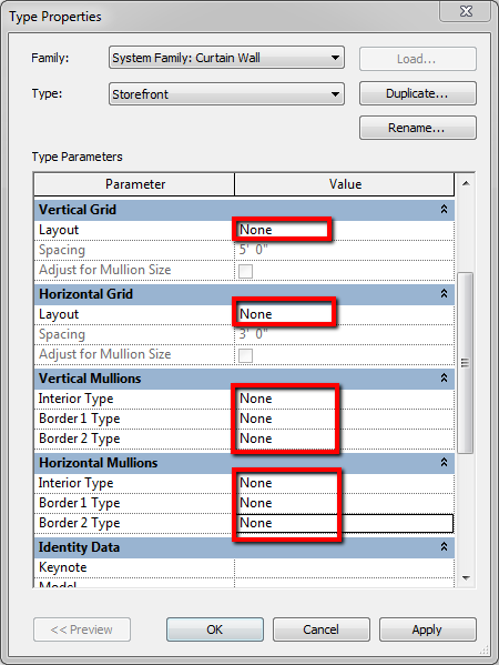
13 Apply best practices for exporting models from Autodesk Revit to Autodesk Simulation CFD Model Simplification When exporting to Simulation CFD, it is recommended that we use a model that is as simplified as possible, since this would ensure a smaller number of nodes, avoid chances of overlapping geometry and hence meshing problems and would also result in quicker solve times. In the following sections, we would see areas where this simplification can most commonly be applied. Curtain Walls Curtain walls are good examples where geometric simplification can be done. When curtain walls are modeled in Revit, all the elements that are required to convey the design intent are used. However, when the model is exported for CFD analysis, this level of detail is not necessary. The image alongside shows a curtain wall and the level of detail to which it has been modeled in Revit. If this model were to be exported the way it is then it would result in an unnecessarily large number of nodes and the resulting time to mesh and analyze the model might increase (the concept of nodes and the process of meshing is explained later). To simplify this we would have to select the curtain wall and edit its Type Properties and this should take us to the Type Properties dialog box where we can change the properties indicated to None. 13
14 14

15 On doing this we would get a warning which tells us that the gridlines will become nonassociated. We can then select Delete Gridline as indicated. Another warning that might show up would indicate that the mullions between panels being joined will be deleted. Selecting the Delete Element(s) button would then result in the curtain wall showing up as indicated below. Further simplification of the geometry can be done by selecting the mullions at the top and bottom and deleting them and this result in a much more simplified window model that can be used for the export. 15


16 Tip: this technique of setting the horizontal and vertical mullions to None might be the best strategy to represent a simplified curtain wall for export to Simulation CFD. Another possibility that could be explored is by using a window family which we shall see next. Windows With windows and doors the editing can be done inside the family itself so that the right level of detail is present in the model. The image on the left shows the window framing that has been modeled and this can be edited inside the family by selecting it and clicking on the Edit Family button on the ribbon. Once inside the family, we can go into the floor plan view and draw an extrusion that represents the glass body and corresponds to the window dimensions. This extrusion would represent the window as a simplified glass body when all the other elements of the window are turned off inside the project and in order to do that, we would have to assign a sub-category to this extrusion and control its visibility in the project. One of the ways in which the extrusion can be assigned a sub-category is by going into the Visibility/Graphics dialog box and selecting 16

17 the Object Styles as indicated in the image and this will open up the Object Styles dialog box. In this dialog box, we can click on New under Modify Subcategories and create a new subcategory for windows and call it Glass-CFD. 17

18 Once this is done, we can select our extrusion (that was just created for the glass) and in the Properties, change the Subcategory parameter to Glass-CFD and also set the Material parameter to Glass if the default glass material is also going to be used in the project. Tip: If the glass material inside the family is going to be customized, then it is recommended that the default glass material not be used because it would be overridden by the glass material inside the project. Hence it is recommended that a duplicate be made for the glass material inside the family and renamed appropriately if it needs to be customized for use in the project. When this family is now loaded into the project, we can go into the Visibility/Graphics dialog box and turn off all the sub-categories for the window as appropriate. Notice how the Glass sub-category is turned off but the Glass CFD sub-category is left on and this will result in a much more simplified model for the window that can then be used for exporting to Autodesk Simulation CFD. 18

19 Doors The same concept that we had applied to windows can equally be applied to doors in order to simplify them before exporting to Simulation CFD. However, with doors, an additional consideration needs to be made. In most cases, the door item in Simulation CFD would be suppressed, meaning that it would not be meshed and used in the analysis. If this is going to be the case, then you might consider not modeling the door at all in the CFD model. Tip: an occasion where you might want to model the door would be to study infiltration and/or exfiltration. If this is the intent, then you would have to model a door with a small gap at the interface of the door and the floor and also have an external volume that has an appropriate boundary condition in Simulation CFD. Furniture Another great example where modeling simplification can be done is with furniture. The image on the left below shows the chair geometry and the details on it. But we can simplify the chair geometry as shown in the image on the right and develop a simpler mesh and reduce the chances of receiving errors when we try to run the simulation. 19

20 In this case, we have further simplified the geometry and represented the chair as shown in the image alongside. Export from a 3D View Tip: It is always recommended that the export be made from a 3D view. If this is not done then the export quality may not be as clean and may result in significant modeling elements missing. To do this we could create separate views just for export to Autodesk Simulation CFD or use a view template in Revit. Another important point to keep in mind when exporting is to turn off all your linked files as Revit will export whatever it sees in the view! Tip: Users familiar with Revit would really see the advantage of using View Templates in this process to create a view very specific for exporting to Autodesk Simulation CFD. By having a View Template, we need not even have a separate view for the export. We could instead use the Temporary View Properties option in Revit 2014 to temporarily apply the view template to this view for the export and then restore the view properties after the export is done. Once this view is made the active view, we can go to the Add-Ins tab and select Launch Active Model on the Autodesk Simulation CFD 2014 panel of the Add-Ins tab and this will launch the application and give us some options that we can configure as shown below. 20

21 On the Design Study Manager dialog box shown above, we can define the name and location for our model. We can also assign a design name and a scenario name. On this dialog box, we also get the option to add to an existing design study and update the design. The option to add to an existing design can be useful for studying different types of designs like different diffuser layouts while the Update Design option can be useful when changes have been made to the Revit model and those changes need to be updated for the CFD model. 21


22 Run analyses and compare modeling scenarios in Autodesk Simulation CFD High sidewall diffusers option 1 Geometry Tools Once the model is launched into Autodesk Simulation CFD, we may see the Geometry Tools dialog box that would automate some basic clean-up of our model before we can begin doing any work on it. The tool can be useful for removing sliver spaces that might prevent a successful mesh generation. Tip: try to generate the mesh without using the Geometry Tools. If the mesh fails to generate, we can always come back to the Geometry Tools to further diagnose the model. Tip: when the model is first brought into Simulation CFD, the Output Bar should show that There were 2 additional parts generated. These additional parts correspond to the air volumes in the room and the plenum which we did not model in Revit. Thus, as long as the air volume is fully enclosed inside Revit, Simulation CFD should automatically generate this air volume when the model is brought into it. If this is not the case, you might want to go back into your CAD model and verify that all volumes are completely enclosed. 22

23 Materials The next step we need to take when setting up the model for CFD analysis is to assign a material to the various geometric entities present in the model. This can be done by selecting a piece of geometry in the model and clicking on the Edit button as shown. On clicking the Edit buttons at either location indicated, we are directed to the Materials dialog box where we can select the material type and name a material from the list. Selecting Edit for the Material value would allow us to edit individual properties for the material thereby customizing it. A database can also be selected if we have a customized library of materials to choose from. 23

24 Rules Rules can be a very useful technique to assign materials and boundary conditions automatically into any file that is brought into the software. It can be accessed by clicking Rules on the Setup tab of the ribbon. This would bring up the Rules Manager where we can begin defining our rules. In the Rules Manager we can click at the spot indicated (1.) to launch the Rule Creation dialog box. In the Rule Creation dialog box we can define a name for the rule, select the way we would like the rule to filter out items and then finally select the material we would like to have applied on these CAD parts. Selecting OK here and then selecting Apply Now would automatically find all the geometric entities that have the word Furniture in them and it would assign them the wood (soft) material. This process can be repeated in a similar manner for other pieces of geometry in the model and we would end up with a number of different rules. Tip: Since there is no direct way right now to ensure that materials assigned in Revit would automatically get mapped and translated into Simulation CFD, we can use rules to automate this process. Simulation CFD would also remember the rules created in one session and would automatically map items based on those rules for any new model as well. The following assumptions were made for the materials in the model in general: 24
 Human Glass wool Glass Note: glass-wool has been assumed as the material for the floor since the floor is on the fourth level and not exposed to external environmental conditions.")
25 Geometry Type Interior Walls Exterior Wall Diffuser body Diffuser inlet/exit Furniture Windows Floor Seated Occupant Ceiling Lights Material Gypsum Board Concrete Aluminum Air Wood (Soft) Glass Flooring (plank) Human Glass wool Glass Note: glass-wool has been assumed as the material for the floor since the floor is on the fourth level and not exposed to external environmental conditions. Air has been assumed as the material for a part of the diffusers since we can apply the boundary conditions to it and have an interaction with the air volume inside the space. Additionally, the air volume has been assigned a variable environment parameter value so that the effect of natural convection (buoyancy) can be taken into account and the property values can vary as the simulation progresses. This process of material assignment can be applied to the various models and options we have considered for this room. 25

26 The image alongside shows the sidewall diffusers and also the air volume that has been applied to the casing of the light fixtures. Boundary Conditions What are boundary conditions? Boundary conditions are known conditions. In other words, if we know certain properties at certain locations for the surface or volume of geometry then we can assign these values at that geometry as known conditions. Boundary conditions act like inputs to the model and help in defining the simulation problem. Pressure boundary condition To begin assigning boundary conditions, we can click on the boundary conditions button of the ribbon. 26
 and then right-clicking as shown in the image alongside.")

27 We now need to access the surface of the diffusers to assign this boundary condition. In order to do this, we would have to hide certain elements in our model. This can be done by selecting the element (for example the roof) and then right-clicking as shown in the image alongside. We can now select the Hide button and this will hide this particular roof element in the view. Tip: if we are able to select surfaces of objects instead of volumes, then the selection of elements can be changed at any point from surfaces to volumes and vice-versa. The tool to do this would be found on the Selection panel of the Setup tab. After hiding elements in this way, we can re-orient the model so that we can view the diffusers and select one of them, in this case, the return grille. On selecting this surface, we would be able to see the shortcuts to edit or remove the boundary condition. We can now click the button shown to edit the boundary condition and we would be able to access the Boundary Conditions dialog box 27
28 We can set up the pressure boundary condition in this way as shown in the image alongside for the return grille. A zero gauge pressure is a good way to approximate the return grille since it would represent the atmospheric pressure at the outlet. Flow boundary condition 28

29 Since we know that the linear slot diffusers are set to supply 482 CFM among 3 units, we can assign a volumetric flow rate of CFM each to the three diffusers in the break room as shown in the image above by hiding appropriate surfaces and selecting them. Tip: when assigning this boundary condition, make sure that the flow direction and units are set correctly. We can edit the flow direction by clicking on Reverse Normal as shown in the image above, if need be. Also, note that the flow has been defined as fully developed. This would be the option to use in this case since we are not studying entrance effects and so it is a more realistic representation of the model. Temperature boundary condition In addition to the flow boundary condition defined above, we also need to define a temperature boundary condition for the inlets since we intend to study the effects of heat transfer as well. We know that the required supply air temperature is 56.8 F and so we can select the surfaces (as previously selected) and set an inlet temperature of 56.8 F. 29

30 We also need to assign a film coefficient or a temperature boundary condition on the walls to simulate the exterior surfaces. Using a film coefficient as a boundary condition might be a more appropriate choice however, in some cases, using this boundary condition to simulate exterior walls has been known to cause divergence. Tip: if this is a scenario you run into then consider using a constant temperature boundary condition instead of using the film coefficient boundary condition. Thus, we can select the exterior walls and windows and assign a constant temperature boundary condition of 88 F as shown in the image below Tip: if running a transient analysis, the temperature boundary condition can also be set to be time-variant allowing you to study problems involving thermal storage. Note: the roof has been modeled but the roof load has been ignored in the load calculations since it cannot be applied as a boundary condtion. This is because Simulation CFD currently does not support a simulation where a surface boundary condition is immersed within the volume (we will elaborate on this point later on). 30


31 Heat generation boundary condition Based on the load calculations, the seated occupant in the room is set to generate 450 Btu/hr. of heat (sensible and latent total). We can now select the seated occupant by hiding all the surrounding volumes. The selection type can be set to Volumes and we can now select the seated occupant and click on Edit, as before and we can set the type to Total Heat Generation and unit to BTU/h and then we can set the value to 450 as shown in the image below. In a similar manner, the volumes representing the lights can also be selected and assigned a heat generation of 30 W each (or 15 W for each half as shown below) Thus to summarize, the following boundary conditions have been applied on the model 31
32 Geometry Exterior walls Human Lights (each) Supply diffuser (each) Return diffuser Boundary Condition 88 F 450 Btu/h 30 W CFM, 56.8 F Zero gauge pressure Meshing What is meshing? Meshing is the process of breaking down the model into a number of smaller elements. These elements are connected together by what are called nodes and the calculations are performed at these nodes. Autodesk Simulation CFD simplifies the process of meshing by automatically generating a mesh. Things like the geometric curvature, gradients and proximity to neighboring elements are all taken into account during the automatic meshing process. Suppress parts During the analysis, there could be parts that do not contribute to the analysis in any way. We can select these parts in the model and suppress them and Autodesk Simulation CFD will not mesh these parts, thus resulting in a fewer number of nodes and elements and quicker solve times. In order to suppress a part, we can select it under Materials and right-click on it. In the list of options visible, we can now select Suppress and this will suppress the part in the model. Parts suppressed in the model would appear with a strike-out across them. 32

33 Tip: perform the part suppression process before meshing the model since suppressed parts are not meshed. If this is done later, then the mesh would have to be re-defined. Tip: the air volume in the plenum would have to be suppressed as shown here because if this is not done then Autodesk Simulation CFD will not be able to detect the inlets and outlets when we run the simulation. This happens because Autodesk Simulation CFD can detect surface boundary conditions only if they are defined at the outer surface of the model. In other words, the inlets and outlets cannot be immersed within the air volume being analyzed. suppressed. For the same reason, the roof has been modeled but the roof load has been ignored in the load calculations (and also has not been applied as a surface temeprature boundary condition) since the air volume adjacent to it has to be Tip: suppressing parts can have a significant impact not only on the solution time but also the generation of the solution itself. As a first option, always try running the simulation with the minimum number of parts suppressed, i.e. only parts that have to be absolutely suppressed. If more parts are suppressed than necessary, divergence might occur in the solution process. Automatic Meshing Once the parts have been suppressed, we can click on Mesh Sizing on the ribbon and we would then have access to the meshing tools. We can then click on Autosize and this would show us the node positions in our model. 33


34 Preview Mesh We can further analyze the mesh by right-clicking on an empty space in the window where the model is visible and then click the Select All button as indicated below. We can then right click again and we have the option to Preview. Selecting this would allow us to preview the mesh and make further adjustments to the mesh like refining it or coarsening it. Notice how the automatic mesh sizing process would automatically generate a coarse mesh around the corners of the model and a fine mesh on and around the occupant. The selective refinement of the mesh would result in a more gradual change in fluid properties when analyzed in the model. 34

35 Solve We are finally in a position to analyze the model. In order to do this, we can click on Solve and this would open up the Solve dialog box. In here, we can choose the number of iterations to run. The results would be compared between successive iterations and if their values fall below a certain threshold, then the results are said to have converged. In this case, we ran the simulation for 100 iterations. The next thing we need to do, is go into Result Quantities as indicated in the image and this would direct us to the Result Quantities dialog box. In this dialog box, we need to make sure that the option for Thermal Comfort is selected so that we can view the Predicted Mean Vote (PMV) and Predicted Percentage Dissatisfied (PPD) values for our model. 35

36 We can also click on the Factors button and verify the thermal comfort factors as shown. The values shown are based on the ASHRAE Handbook Fundamentals for metabolic rate and clothing. Once this is done, on the Physics tab, we can select the kind of physics we would like to have involved in the model. By default, we just have the flow option selected. In order to simulate our analysis, we need to apply heat transfer and radiation so that the effects of heat generation can also be taken into account during the analysis. Tip: if the radiation option is not selected, then we would not be able to view the PMV and PPD results. Thus, in order to study thermal comfort and look at PMV results, the radiation option must be selected. Once these settings have been configured, we can click on Solve and this will run the simulation. 36

37 If using Simulation CFD 360, we can use the Simulation Job Manager to track the process of uploading, running and downloading the simulation. The image alongside shows an example of the simulation running on Simulation 360. Results Once the analysis has been completed, we can view the convergence plot which gives convergence information about the different variables. Tip: the convergence monitor might be a good tool to access the model and see if convergence has been achieved manually. Flatter curves indicate that the values are not changing significantly from iteration-to-iteration and so can be used to declare convergence. This method 37
38 of manually observing the convergence plot might be particularly useful for models that simulate rotating, motion or vortex shedding analyses to declare convergence What are the measures of an optimum airflow design?* This might be a good time to discuss the factors that should be considered for determining if the design is optimized for the airflow in a given space. Some of these measures are as listed below: 1. Predicted mean vote (PMV): PMV basically indicates how comfortable a group of occupants are in a conditioned space based on the ASHRAE thermal sensation scale shown below 2. Predicted percentage dissatisfied (PPD): PPD is a quantitative prediction of the percentage of people dissatisfied with the thermal conditions, as determined by the PMV. 3. Velocity must be at or below 50 feet per minute (fpm) within 1 foot from the walls and vertically between 6 and 6 4. Difference in temperature between ankle and head positions (for a seated occupant) is 3.6 F 5. The average air temperature is between F 6. There is maximum mixing of air in the room In addition to these guidelines, for maximum energy conservation, the goal must be to maintain proper temperatures at the lowest possible speed. * These are comfort limits set by ASHRAE Handbook, ASHRAE Standard 55 and ISO Standard 7730 With these points in mind, let us look at the results for the high sidewall diffuser case. 38

39 PMV Since Thermal Comfort was selected as a result quantity, we can view this by go to the View tab and set the Visual Style to Outline as indicated for the entire model. The next thing we need to do is set the seated occupant to a shaded style by selecting it in the Results portion of the Design Study Bar and right-clicking on it as shown in the image to the left. Once this is done, we can then set the Global Result quantity to Predicted Mean Vote. On doing this, we should see an image similar to the one shown below As can be seen in this image, the occupants would be feeling hot for this configuration. Thus this setup might not be ideal for the room under consideration. 39
 Supply diffuser (each) Return diffuser Boundary Condition")
40 High sidewall diffusers option 2 Materials The material assignment process is similar for this option and would result in a model that would appear as shown below. Boundary conditions In this case the boundary conditions used are as described in the table below Geometry Exterior walls Human Lights (each) Supply diffuser (each) Return diffuser Boundary Condition 88 F 450 Btu/h 30 W CFM, 56.8 F Zero gauge pressure 40
41 Meshing The default mesh configuration was used and based on that, the mesh distribution shown below was obtained Solve The same settings that we had for the option 1 were used for this option as well for describing the solution process. Results The convergence monitor plot for this option is as shown below. 41
42 Based on the convergence plot shown above, we can see that the temperature profile is reasonably flat while the velocity profiles are still fluctuating. Thus, running the simulation for a higher number of iterations might help in obtaining flatter curves for the velocities as well. PMV As can be seen from the image above, the PMV for the scale indicated shows that the occupants sitting closer to the exterior wall would be slightly warm on the upper body while the lower body would be on the slightly cool side of the scale. PPD We can see that the PPD value for the scale shown results in some localized hot spots for this option. 42

43 Velocity must be at or below 50 feet per minute (fpm) within 1 foot from the walls and vertically between 6 and 6 This result can be validated be creating an iso-surface. An isosurface allows showing surfaces that have the same value for a particular parameter. As can be seen in the image, the iso-surface is showing all points in the model where the velocity is 50 fpm and the coloring is based on the temperature scale shown. We can see here that apart from the area around the inlets, this criterion is being met by this option. 43

44 Difference in temperature between ankle and head positions (for a seated occupant) is 3.6 F In order to verify this we could use planes. We can draw a plane at the approximate midposition of each occupant and pick points near the ankle and head and plot the temperature profile. This can be done for each of the three occupants and a plot similar to the one shown below can be obtained which would automatically draw a line connecting the two points picked as shown above and add a third point mid-way between them as can be seen in the plot below. We can average out the difference in values for each occupant and then compare the value with the recommended value of 3.6 F. In this case, the difference in temperatures between the head and ankle positions is F which exceeds the recommended value. 44

45 The average air temperature is between 73 and 77 F This result can be tested by clicking on Summary File on the Results tab and this should open up a window that shows the summary results for the model. In this case we can see that the mean temperature after 100 iterations is F. The average velocity can also be obtained for this configuration and it is as shown below in feet/ second. Mixing of air This result can again be verified by using an iso-surface. In this case, the iso-surface shows areas in the model where the velocity is 20 fpm and the coloring is based again on the temperature scale. As can be seen from the image below, there are large areas within the model where the velocity is below 20 FPM. Thus, we can conclude that for this option, the mixing is not as effective as we would desire. 45

")
46 A combination of perforated ceiling diffusers & square ceiling diffusers option 1 Materials For this model, the material assignment process can be done in a similar manner to the high sidewall diffuser. The only exception here would be the application of a resistance material to represent the perforated face of the return diffusers. This can be done by selecting the diffuser face as shown (1.) and then clicking on the browse button (2.). This would open up the Flow Direction dialog box, where we can select Z to indicate the 46

47 positive Z direction for the flow. Tip: a resistance material would be ideal for any geometry that has perforations on it. This could include items like filters and even perforated floors that might be used in data centers. We can also click on Edit on Material (shown above) and this would open up the Material Editor dialog box that would allow us to customize this material by changing the Save to database option and then assigning a different free area ratio for this resistance material. The free area ratio is the ratio of open area to total area for the surfaces of the volume. Tip: saving materials to a unique database would allow using this material for other simulations as well in the future. 47
48 Boundary Conditions Boundary conditions are also assigned in a similar manner to the previous case however; in this case, since we have just 2 inlets for the air, we would have each one of them diffuse 241 CFM. The table below presents a summary of the boundary conditions Geometry Exterior walls Human Lights (each) Supply diffuser (each) Return diffuser Boundary Condition 88 F 450 Btu/h 30 W 241 CFM, 56.8 F Zero gauge pressure Meshing For the meshing, the automatic mesh sizing was performed with the default settings. Solve Similar settings to the high sidewall diffuser case were used to define the solution parameters. Results The image alongside shows the convergence monitor plot for this case and as can be seen here, the velocity components are highly unstable for this configuration which has led to divergence. Thus, this solution also might not be the best possible solution for effectively cooling our room. 48

49 A combination of perforated ceiling diffusers & square ceiling diffusers option 2 Materials The process of material assignment would be similar to option1 above and would appear as shown below Boundary Conditions Assigning boundary conditions would be done by selecting surfaces and volumes, depending on the type of boundary condition that needs to be assigned. 49

50 In general, the following boundary conditions have been used: Geometry Exterior walls Human Lights (each) Supply diffuser (each) Return diffuser Boundary Condition 88 F 450 Btu/h 30 W CFM, 56.8 F Zero gauge pressure Meshing and Solve For this option, the meshing and solution settings would be very similar to option 1. Results In this case, we are able to get results up to 100 iterations and we can see that there is some flattening of the temperature curve (in red) but the velocity curves are not as flat as we would like. 50


51 PMV We can again set the current variable to PMV for the global results and then view the predicted mean vote as shown in the image alongside. As we can see in the image, the upper body of the occupants is in the neutral to slightly warm range and the lower body is in the neutral to slightly cool range. PPD The PPD results reinforce the results we see for the PMV. We can see here also that the upper body of the occupants for the most part has a PPD value less than 10%. The shoulders and the ankle portion have a slightly higher PPD value. 51
52 Velocity must be at or below 50 feet per minute (fpm) within 1 foot from the walls and vertically between 6 and 6 This point can be addressed using an iso-surface. Iso-surfaces are great tools to identify flow patterns in the simulation model. The iso-surfaces in the image above show areas in the model where the velocity is 50 fpm and the coloring is based on the temperature scale. The image above shows that this option does not meet the condition as we can see a fairly large area (away from the walls) at the 50 fpm value. Additionally, we can also observe that we have a column of air at 50 fpm from the diffusers and, thus we might want to increase the number of diffusers so that the temperature requirements are met at a lower velocity. Difference in temperature between ankle and head positions (for a seated occupant) is 3.6 F In order to verify this we could again use planes as before. We can draw a plane at the approximate mid-position of each occupant and pick points near the ankle and head and plot the temperature profile. 52


53 In this case, the average temperature difference is 4.9 F which is higher than the recommended range. 53

54 The average air temperature is between 73 and 77 F As can be seen here, the mean value for the temperature is F which is slightly above the recommended range. Note: given that we have run only 100 iterations, the magnitude of these results should not be taken as highly accurate. Ideally, we would want to run a higher number of iterations and also perform mesh adaptation so that the results are truly mesh independent. The image below shows the mean velocity in feet/second (ft/s) for this option. Mixing of air We can use iso-surfaces again to identify areas of stagnation (velocity less than 15 fpm) within the model. This might indicate alternate locations for the return diffusers to promote mixing and more efficient operation of the supply units if a higher return air temperature from the stagnation region results. 54
55 The image above shows surfaces in the model where the velocity is at 20 fpm and the color is based on the temperature. We can also see the stagnation region and thus consider moving one of the return diffusers to that location to promote better mixing of air. 55
 assigned to the inlet (and outlet) and aluminum material assigned")
56 Linear slot ceiling diffusers option 1 Materials The process of material assignment again is very similar to what we have been seeing so far. The image alongside shows how the linear diffusers are having an air material (blue color) assigned to the inlet (and outlet) and aluminum material assigned to the slots. 56
 Supply diffuser (each) Return diffuser Boundary Condition 88 F 450 Btu/h 30 W 120.5 CFM, 56.")
57 Boundary Conditions The boundary conditions can be applied in a similar manner for this option as well. In general, the boundary conditions shown below have been used for this option. Geometry Exterior walls Human Lights (each) Supply diffuser (each) Return diffuser Boundary Condition 88 F 450 Btu/h 30 W CFM, 56.8 F Zero gauge pressure Meshing and Solve The Auto-Size option was used for meshing the model and the default node and element locations were considered for this option. The options on the Solve dialog box were also set up similar to the other options that we have looked at so far. Results The convergence plot here shows that there is some flattening of the temperature curve however the velocity components are still fluctuating and so running the simulation for a larger number of iterations might result in flatter curves for the velocity as well. 57
58 PMV The image shown alongside follows the same trend we have been seeing so far with the upper body in the neutral to slightly warm range and the lower body in the neutral to slightly cool range. PPD The PPD results show that the lower body is within the 10% range whereas the upper body on the front and back sides are roughly in the 15-20% range. 58
59 Velocity must be at or below 50 feet per minute (fpm) within 1 foot from the walls and vertically between 6 and 6 We can again use iso-surfaces to obtain an image similar to the one that is shown above that highlights surfaces that are at 50 fpm for the velocity and are colored based on the temperature scale. Comparing this image with the one we had for the previous case, we can see that there is a smaller spread of high velocity air in the room and the vertical column of air is limited to the diffuser locations in this case. Difference in temperature between ankle and head positions (for a seated occupant) is 3.6 F This result can again be verified by creating a plane as in the previous case and in this case, the average temperature difference between the ankle and head positions turned out to be F which is well within the recommended range of 3.6 F. 59
60 The image alongside shows one such plane that is used to obtain the temperature differential between the ankle and head positions. The average air temperature is between 73 and 77 F recommended range. We can view the Summary File in a similar manner to the previous case and make a note of the average temperature across the room. In this case again we see that the average room air temperature is slightly over the 60


61 The average velocity in the room is shown for each of the iterations in feet per second. a lower velocity. The value at the 100 th iteration is higher than the corresponding value for the previous case and so at this point, the previous case might be a better option from an energy standpoint since it achieves approximately the same temperature at Mixing of air 61

62 As can be seen in the image above, we can see that the points where the average velocity is at or above 20 fpm is greater than in the previous case. Since there are no stagnation areas identifiable in this case, we can assume better mixing of air than in the previous case. Linear slot ceiling diffusers option 2 Materials In this option, the material assignment would follow the same process that we have been using so far. We can see the fewer number of slots being used for this model. 62
63 Boundary Conditions Geometry Exterior walls Human Lights (each) Supply diffuser (each) Return diffuser Boundary Condition 88 F 450 Btu/h 30 W 20.5 CFM, 56.8 F Zero gauge pressure The table above is a summary of the boundary conditions that are being used for this option. Meshing and Solve The meshing and solve options are again set up the way they were for the previous cases. Results Again, we see from the convergence plot that the temperature and y-component of velocity are flat. To obtain flat curves for the other variables, we may want to consider running a higher number of iterations. 63


64 PMV The PMV results again show the same trend with the upper body in the neutral to slightly warm range and the lower body in the neutral to slightly cool range. PPD The PPD results show that the head and upper body areas are very close to 0% whereas the lower body is in the % range. 64
 is 3.")
65 Velocity must be at or below 50 feet per minute (fpm) within 1 foot from the walls and vertically between 6 and 6 Again, creating iso-surface, we can see that in this case, there is a fairly large spread of high velocity air than what we had for the previous case with linear slot diffusers. Difference in temperature between ankle and head positions (for a seated occupant) is 3.6 F This point can again be verified by creating planes and plotting the temperature variations across the ankle and head positions. 65


66 In this case, the average temperature difference was found to be F. Thus as far as this point is concerned, we could go with either of the two linear slot diffuser options for the layout. The average air temperature is between 73 and 77 F Again, looking at the Summary File, we can see the average temperature across the room. 66
67 The average velocity can also be found out and is as shown in the image below (ft/s) Note: given that the velocity components on the convergence plot are still fluctuating, we cannot consider these values as highly accurate at this point. Mixing of air Again, we see that we have better mixing patterns than the case with square ceiling diffusers. Conclusion In conclusion, we have tangible results for four of the six cases we have considered for the layout of diffusers in this room. The sidewall option 1 showed us that the occupants would not be comfortable. This could either be due to the placement of the diffusers or the type of diffusers used. The first option for the combination of perforated ceiling diffusers and square ceiling diffusers showed us that the velocity profiles were highly unstable and this lead to divergence. The table below summarizes the results for the remaining four cases that we had looked at. 67
68 Comparison parameter High sidewall diffuser - option 2 A combination of perforated ceiling diffusers and square ceiling diffusers option 2 Linear slot ceiling diffusers option 1 Linear slot ceiling diffusers option 2 PMV Slightly warm upper body slightly cool lower body Neutral to slightly warm upper body and neutral to slightly cool lower body Neutral to slightly warm upper body and neutral to slightly cool lower body Neutral to slightly warm upper body and neutral to slightly cool lower body PPD Localized hot spots with higher percent dissatisfied Higher percentage dissatisfied Minimum percent dissatisfied Higher percentage dissatisfied Velocity must be at or below 50 feet per minute (fpm) within 1 foot from the walls and vertically between 6 and 6 Fewer number of points with velocity at 50 fpm Large number of points with velocity at 50 fpm Fewer number of points with velocity at 50 fpm Large number of points with velocity at 50 fpm Difference in temperature between ankle and head positions (for a seated occupant) is 3.6 F Does not meet this criterion Does not meet this criterion Meets this criterion Meets this criterion The average air temperature is Exceeds criterion Exceeds criterion Exceeds criterion Exceeds criterion 68
69 between 73 & 77 degree F (80.88 F) (80.65 F) ( F) (79.73 F) Average velocity (ft/s) ft/s ft/s ft/s ft/s Mixing of air Poor mixing Poor mixing Good mixing Good mixing Thus, based on the above comparisons, we can conclude that both options for the linear slot ceiling diffusers might work better compared to the square ceiling diffusers and high sidewall diffusers. The first option has four supply diffusers compared to six in the second option and so the first option might allow for a lower first cost as well. Future work The following items can be considered as future work that would enhance the results and add variations to the different configurations considered. Run the simulation for a higher number of iterations The solution process is iterative and so the results from the previous iteration are used in the current iteration and this process is repeated till the difference in values for successive iterations falls below a certain threshold. Thus one way to obtain convergence and more accurate results is by running the simulation for a higher number of iterations. Perform mesh adaptation studies This might also be necessary to obtain more accurate results for our models. The results that are obtained initially might be dependent on the given mesh. Thus the mesh would have to be refined to a point where the results are not changing significantly from the previous mesh distribution. This is when the results are said to be mesh-independent. Autodesk Simulation CFD can automate this process by performing mesh adaptation cycles where the results from the first mesh are saved in a new scenario and run on a more improvised mesh. Thus, mesh adaptation would have to be performed to get mesh independent results. Optimize design for minimum and maximum air flow This is another area that can be explored to see if it is possible to find the layout that would meet all the criteria highlighted above for the minimum flow and the maximum flow for a VAV system. 69

70 Update and develop optimized designs in Autodesk Revit MEP Once the design optimization has been performed in Simulation CFD, we can then finalize this design in Revit. We can do this by opening up the view that shows the last diffuser layout that we had for our model Let us assume that we would like to use the first option with linear slot ceiling diffusers to lower down the first costs. Thus, we can now select the diffusers in the middle and delete them as shown. We can now move the other remaining diffusers to the positions that we had for the 70
71 first option with linear slot ceiling diffusers. If parameters are being used to control the size and number of slots, we can then edit these values to match the configuration we had used and the resulting layout should resemble the first option we had used for linear slot ceiling diffusers. 71
72 Tip: the use of design options might also be a good idea to study different diffuser layouts and compare them in Simulation CFD and once the best layout has been selected, the other design options can be removed. References: Titus Diffuser Catalog Titus Engineering Guidelines Trane Trace
AB3080 L. Learning Objectives: About the Speaker:
 AB3080 L While architects have tested their designs in wind tunnels for many years, the process is typically outsourced to engineering firms and not easily accessible to architects during the conceptual
Learning Module 4 - Thermal Fluid Analysis Note: LM4 is still in progress. This version contains only 3 tutorials.
 Learning Module 4 - Thermal Fluid Analysis Note: LM4 is still in progress. This version contains only 3 tutorials. Attachment C1. SolidWorks-Specific FEM Tutorial 1... 2 Attachment C2. SolidWorks-Specific
Verizon SMARTS Data Center Design Phase 1 Conceptual Study Report Ms. Leah Zabarenko Verizon Business 2606A Carsins Run Road Aberdeen, MD 21001
 Verizon SMARTS Data Center Design Phase 1 Conceptual Study Report Ms. Leah Zabarenko Verizon Business 2606A Carsins Run Road Aberdeen, MD 21001 Presented by: Liberty Engineering, LLP 1609 Connecticut Avenue
AIR DISTRIBUTION FOR COMFORT AND IAQ
 AIR DISTRIBUTION FOR COMFORT AND IAQ Heating Piping and Air Conditioning March 1998 Dan Int-Hout Chief Engineer KRUEGER EXCELLENCE IN AIR DISTRIBUTION Modern environmentally controlled spaces consume significant
Excel -- Creating Charts
 Excel -- Creating Charts The saying goes, A picture is worth a thousand words, and so true. Professional looking charts give visual enhancement to your statistics, fiscal reports or presentation. Excel
Air, Fluid Flow, and Thermal Simulation of Data Centers with Autodesk Revit 2013 and Autodesk BIM 360
 Autodesk Revit 2013 Autodesk BIM 360 Air, Fluid Flow, and Thermal Simulation of Data Centers with Autodesk Revit 2013 and Autodesk BIM 360 Data centers consume approximately 200 terawatt hours of energy
Handout: Word 2010 Tips and Shortcuts
 Word 2010: Tips and Shortcuts Table of Contents EXPORT A CUSTOMIZED QUICK ACCESS TOOLBAR... 2 IMPORT A CUSTOMIZED QUICK ACCESS TOOLBAR... 2 USE THE FORMAT PAINTER... 3 REPEAT THE LAST ACTION... 3 SHOW
2013 Code_Saturne User Group Meeting. EDF R&D Chatou, France. 9 th April 2013
 2013 Code_Saturne User Group Meeting EDF R&D Chatou, France 9 th April 2013 Thermal Comfort in Train Passenger Cars Contact For further information please contact: Brian ANGEL Director RENUDA France [email protected]
CFD ANALYSIS CHALLENGES IN BUILDING SIMULATION FOR SIMBUILD2004 CONFERENCE. Ferdinand Schmid and Galen Burrell Architectural Energy Corporation
 CFD ANALYSIS CHALLENGES IN BUILDING SIMULATION FOR SIMBUILD2004 CONFERENCE Ferdinand Schmid and Galen Burrell Architectural Energy Corporation ABSTRACT This paper discusses the capabilities and challenges
TABLE OF CONTENTS. INTRODUCTION... 5 Advance Concrete... 5 Where to find information?... 6 INSTALLATION... 7 STARTING ADVANCE CONCRETE...
 Starting Guide TABLE OF CONTENTS INTRODUCTION... 5 Advance Concrete... 5 Where to find information?... 6 INSTALLATION... 7 STARTING ADVANCE CONCRETE... 7 ADVANCE CONCRETE USER INTERFACE... 7 Other important
Problem Statement In order to satisfy production and storage requirements, small and medium-scale industrial
 Problem Statement In order to satisfy production and storage requirements, small and medium-scale industrial facilities commonly occupy spaces with ceilings ranging between twenty and thirty feet in height.
Basic Selection & Proper Application of Overhead Air Distribution Devices
 Basic Selection & Proper Application of Overhead Air Distribution Devices GRD Selection & Application Terms Selection Throw Sound Installation Variations affect Performance Inlet Effects Basics Return
Kitchen and Bath Design Tutorial
 Adding Cabinets Chapter 5: Kitchen and Bath Design Tutorial This tutorial continues where the Materials Tutorial left off. You should save this tutorial using a new name to archive your previous work.
Collaborating Across Disciplines with Revit Architecture, MEP, and Structure
 Collaborating Across Disciplines with Revit Architecture, MEP, and Structure David Cohn AB104-3 Are you ready to take the next step and use building information modeling to share data across the entire
Content Author's Reference and Cookbook
 Sitecore CMS 6.5 Content Author's Reference and Cookbook Rev. 110621 Sitecore CMS 6.5 Content Author's Reference and Cookbook A Conceptual Overview and Practical Guide to Using Sitecore Table of Contents
Using CFD for optimal thermal management and cooling design in data centers
 www.siemens.com/datacenters Using CFD for optimal thermal management and cooling design in data centers Introduction As the power density of IT equipment within a rack increases and energy costs rise,
. Address the following issues in your solution:
 CM 3110 COMSOL INSTRUCTIONS Faith Morrison and Maria Tafur Department of Chemical Engineering Michigan Technological University, Houghton, MI USA 22 November 2012 Zhichao Wang edits 21 November 2013 revised
Kitchen and Bath Design Tutorial
 Adding Cabinets Kitchen and Bath Design Tutorial This tutorial continues where the Interior Design Tutorial left off. You should save this tutorial using a new name to archive your previous work. The tools
Getting Started with Web Service Tools for Whole Building Analysis
 Autodesk Ecotect Analysis 2010 Getting Started with Web Service Tools for Whole Building Analysis Customers who add subscription to their Autodesk Ecotect Analysis license can access 1 whole building energy,
Roof Tutorial. Chapter 3:
 Chapter 3: Roof Tutorial The majority of Roof Tutorial describes some common roof styles that can be created using settings in the Wall Specification dialog and can be completed independent of the other
Tutorial: 3D Pipe Junction Using Hexa Meshing
 Tutorial: 3D Pipe Junction Using Hexa Meshing Introduction In this tutorial, you will generate a mesh for a three-dimensional pipe junction. After checking the quality of the first mesh, you will create
Data representation and analysis in Excel
 Page 1 Data representation and analysis in Excel Let s Get Started! This course will teach you how to analyze data and make charts in Excel so that the data may be represented in a visual way that reflects
Raising the Roof Creating Roofs in Revit David Cohn
 David Cohn AB322-1 Roofs are one of the most complex architectural elements to model, but with Revit you can create just about any type of roof. This class will explore the best methods for creating various
SECTION EG. Engineering Guide Air Distribution. Please refer to the Price Engineer s HVAC Handbook for more information on Air Distribution.
 SECTION EG Air Distribution Please refer to the Price Engineer s HVAC Handbook for more information on Air Distribution. Space Air Diffusion AIR DISTRIBUTION ENGINEERING GUIDE Proper selection of air diffusion
Direct and Reflected: Understanding the Truth with Y-S 3
 Direct and Reflected: Understanding the Truth with Y-S 3 -Speaker System Design Guide- December 2008 2008 Yamaha Corporation 1 Introduction Y-S 3 is a speaker system design software application. It is
Analysis of the UNH Data Center Using CFD Modeling
 Applied Math Modeling White Paper Analysis of the UNH Data Center Using CFD Modeling By Jamie Bemis, Dana Etherington, and Mike Osienski, Department of Mechanical Engineering, University of New Hampshire,
Introduction to ANSYS
 Lecture 3 Introduction to ANSYS Meshing 14. 5 Release Introduction to ANSYS Meshing 2012 ANSYS, Inc. March 27, 2014 1 Release 14.5 Introduction to ANSYS Meshing What you will learn from this presentation
Eco Pelmet Modelling and Assessment. CFD Based Study. Report Number 610.14351-R1D1. 13 January 2015
 EcoPelmet Pty Ltd c/- Geoff Hesford Engineering 45 Market Street FREMANTLE WA 6160 Version: Page 2 PREPARED BY: ABN 29 001 584 612 2 Lincoln Street Lane Cove NSW 2066 Australia (PO Box 176 Lane Cove NSW
Using Computational Fluid Dynamics (CFD) for improving cooling system efficiency for Data centers
 for improving cooling system efficiency for Data centers") Data Centre Best Practises Workshop Using Computational Fluid Dynamics (CFD) for improving cooling system efficiency for Data centers Shishir Gupta 17 th March 2009 You are Here Introduction to CFD Data
Data Centre Best Practises Workshop Using Computational Fluid Dynamics (CFD) for improving cooling system efficiency for Data centers Shishir Gupta 17 th March 2009 You are Here Introduction to CFD Data
History Explorer. View and Export Logged Print Job Information WHITE PAPER
 History Explorer View and Export Logged Print Job Information WHITE PAPER Contents Overview 3 Logging Information to the System Database 4 Logging Print Job Information from BarTender Designer 4 Logging
Tutorial: 2D Pipe Junction Using Hexa Meshing
 Tutorial: 2D Pipe Junction Using Hexa Meshing Introduction In this tutorial, you will generate a mesh for a two-dimensional pipe junction, composed of two inlets and one outlet. After generating an initial
Information Literacy Program
 Information Literacy Program Excel (2013) Advanced Charts 2015 ANU Library anulib.anu.edu.au/training [email protected] Table of Contents Excel (2013) Advanced Charts Overview of charts... 1 Create a chart...
House Design Tutorial
 Chapter 2: House Design Tutorial This House Design Tutorial shows you how to get started on a design project. The tutorials that follow continue with the same plan. When we are finished, we will have created
All in the Family: Creating Parametric Components in Autodesk Revit
 All in the Family: Creating Parametric Components in Autodesk Revit Matt Dillon D C CADD AB2100 The key to mastering Autodesk Revit Architecture, Autodesk Revit MEP, or Autodesk Revit Structure software
Session 25 Revit MEP Tips and Tricks
 Session 25 Revit MEP Tips and Tricks Page 1 of 17 Sometimes it's the little things which make all the difference. I thought I would share some nifty tricks that can help make Revit MEP go down a little
Kitchen and Bath Design Tutorial
 Chapter 5: Kitchen and Bath Design Tutorial This tutorial continues where the Materials Tutorial left off. You should save this tutorial using a new name to archive your previous work. The tools and techniques
VAV Laboratory Room Airflow The Lowdown on Turndown
 Technology Report March, 2003 VAV Laboratory The Lowdown on Turndown Turndown comparison of these two turndown ratios. Note the small actual airflow difference between them. control ranges are normally
Scientific Graphing in Excel 2010
 Scientific Graphing in Excel 2010 When you start Excel, you will see the screen below. Various parts of the display are labelled in red, with arrows, to define the terms used in the remainder of this overview.
Methods for Effective Room Air Distribution. Dan Int-Hout Chief Engineer, Krueger Richardson, Texas
 Methods for Effective Room Air Distribution Dan Int-Hout Chief Engineer, Krueger Richardson, Texas Agenda Overview LEED issues and Update Perimeter Acoustics Thermal Comfort IAQ / Standard 62.1 Update
1051-232 Imaging Systems Laboratory II. Laboratory 4: Basic Lens Design in OSLO April 2 & 4, 2002
 05-232 Imaging Systems Laboratory II Laboratory 4: Basic Lens Design in OSLO April 2 & 4, 2002 Abstract: For designing the optics of an imaging system, one of the main types of tools used today is optical
Introduction to ANSYS ICEM CFD
 Workshop 8.2 3D Pipe Junction 14.5 Release Introduction to ANSYS ICEM CFD 2012 ANSYS, Inc. April 1, 2013 1 Release 14.5 3D Pipe Junction 3D Pipe Junction This is a simple 4-way pipe intersection with two
Exercise 9-6 Creating a Window Family
 Exercise 9-6 Creating a Window Family Estimated Time: File: 10 minutes ex8-5, generic model wall based.rft This exercise reinforces the following skills: Standard Component Families Templates We want to
Trace Layer Import for Printed Circuit Boards Under Icepak
 Tutorial 13. Trace Layer Import for Printed Circuit Boards Under Icepak Introduction: A printed circuit board (PCB) is generally a multi-layered board made of dielectric material and several layers of
Diego Ibarra Christoph Reinhart Harvard Graduate School of Design
 Building Performance Simulation for Designers - Energy DesignBuilder // EnergyPlus Tutorial #3 Construction Assemblies, Load Reduction & Shading GEOMETRY LOADS RESULTS Diego Ibarra Christoph Reinhart Harvard
How To Create A View Frame In 3D
 12/4/2008-10:00 am - 11:30 am Room:Palazzo O-P (5th) The Secrets of Cutting Plan and Profile Sheets in AutoCAD Civil 3D Michelle Rasmussen - Application Engineer, IMAGINiT Technologies CV304-1P In this
How To Improve Energy Efficiency Through Raising Inlet Temperatures
 Data Center Operating Cost Savings Realized by Air Flow Management and Increased Rack Inlet Temperatures William Seeber Stephen Seeber Mid Atlantic Infrared Services, Inc. 5309 Mohican Road Bethesda, MD
BIM Test At ASHRAE HQ
 This article was published in ASHRAE Journal, April 2011. Copyright 2011 American Society of Heating, Refrigerating and Air-Conditioning Engineers, Inc. Posted at www.ashrae.org. This article may not be
Windows XP Pro: Basics 1
 NORTHWEST MISSOURI STATE UNIVERSITY ONLINE USER S GUIDE 2004 Windows XP Pro: Basics 1 Getting on the Northwest Network Getting on the Northwest network is easy with a university-provided PC, which has
Creating Online Surveys with Qualtrics Survey Tool
 Creating Online Surveys with Qualtrics Survey Tool Copyright 2015, Faculty and Staff Training, West Chester University. A member of the Pennsylvania State System of Higher Education. No portion of this
Content Author's Reference and Cookbook
 Sitecore CMS 6.2 Content Author's Reference and Cookbook Rev. 091019 Sitecore CMS 6.2 Content Author's Reference and Cookbook A Conceptual Overview and Practical Guide to Using Sitecore Table of Contents
Creating Steel Fabrication Friendly Families and Schedules with Autodesk Revit Structure
 Creating Steel Fabrication Friendly Families and Schedules with Autodesk Revit Structure Tina Bos Herold Engineering Limited SE3048-L Once you have mastered the day-to-day use of Autodesk Revit Structure,
Creating Drawings in Pro/ENGINEER
 6 Creating Drawings in Pro/ENGINEER This chapter shows you how to bring the cell phone models and the assembly you ve created into the Pro/ENGINEER Drawing mode to create a drawing. A mechanical drawing
Heat Transfer by Free Convection
 Heat Transfer by Free Convection Introduction This example describes a fluid flow problem with heat transfer in the fluid. An array of heating tubes is submerged in a vessel with fluid flow entering at
Getting Started with ANSYS ANSYS Workbench Environment
 Getting Started with ANSYS ANSYS Workbench Environment Overview The purpose of this tutorial is to get you started with the ANSYS Workbench environment. We will use a simple, static analysis of a single
Roof Tutorial. Chapter 3:
 Chapter 3: Roof Tutorial The first portion of this tutorial can be completed independent of the previous tutorials. We ll go over some common roof styles that can be created using settings in the Wall
HVAC Calculations and Duct Sizing
 PDH Course M199 HVAC Calculations and Duct Sizing Gary D. Beckfeld, M.S.E., P.E. 2007 PDH Center 2410 Dakota Lakes Drive Herndon, VA 20171-2995 Phone: 703-478-6833 Fax: 703-481-9535 www.pdhcenter.com An
Steady Flow: Laminar and Turbulent in an S-Bend
 STAR-CCM+ User Guide 6663 Steady Flow: Laminar and Turbulent in an S-Bend This tutorial demonstrates the flow of an incompressible gas through an s-bend of constant diameter (2 cm), for both laminar and
Conceptual Design and Analysis in Autodesk Revit Architecture 2011
 AUTODESK REVIT ARCHITECTURE 2011 Conceptual Design and Analysis in Autodesk Revit Architecture 2011 In this white paper, CASE Design, a design technology consultancy based in New York City, describes how
Microsoft Excel 2010 Charts and Graphs
 Microsoft Excel 2010 Charts and Graphs Email: [email protected] Web Page: http://training.health.ufl.edu Microsoft Excel 2010: Charts and Graphs 2.0 hours Topics include data groupings; creating
CREATING EXCEL PIVOT TABLES AND PIVOT CHARTS FOR LIBRARY QUESTIONNAIRE RESULTS
 CREATING EXCEL PIVOT TABLES AND PIVOT CHARTS FOR LIBRARY QUESTIONNAIRE RESULTS An Excel Pivot Table is an interactive table that summarizes large amounts of data. It allows the user to view and manipulate
Window Thermal Performance Optimization in Governmental Emirati Housing Prototype in Abu Dhabi, UAE
 Window Thermal Performance Optimization in Governmental Emirati Housing Prototype in Abu Dhabi, UAE Abuimara, Tareq A 1 ; Tabet Aoul, Kheira A. 1 1 Department of Architectural Engineering, United Arab
Energy Efficient Data Center Design. Can Ozcan Ozen Engineering Emre Türköz Ozen Engineering
 Energy Efficient Data Center Design Can Ozcan Ozen Engineering Emre Türköz Ozen Engineering 1 Bio Can Ozcan received his Master of Science in Mechanical Engineering from Bogazici University of Turkey in
Power and Cooling for Ultra-High Density Racks and Blade Servers
 Power and Cooling for Ultra-High Density Racks and Blade Servers White Paper #46 Introduction The Problem Average rack in a typical data center is under 2 kw Dense deployment of blade servers (10-20 kw
Mastercam X6 Basic 3D Design
 Basic 3D Design mastercam x getting started tutorials Mastercam X6 Basic 3D Design December 2011 Be sure you have the latest information! Information might have been changed or added since this document
Taco Hydronic System Solutions Quick Start Guide
 QUICK START GUIDE Taco Hydronic System Solutions Quick Start Guide Contents Help Resources...3 Introduction...4 Taco Hydronic System Solutions Work Screen Introduction...5 The basics...6 Getting Started
The Effect of Forced Air Cooling on Heat Sink Thermal Ratings
 zpero 1 The Effect of Forced Air Cooling on Heat Sink Thermal Ratings By Paul Bachman, Fellow Engineer & Ronnie Haiduk, Applications Engineer, Crydom, Inc. ABSTRACT A heat sink s ability to dissipate thermal
An introduction to 3D draughting & solid modelling using AutoCAD
 An introduction to 3D draughting & solid modelling using AutoCAD Faculty of Technology University of Plymouth Drake Circus Plymouth PL4 8AA These notes are to be used in conjunction with the AutoCAD software
Set up and solve a transient problem using the pressure-based solver and VOF model.
 Tutorial 18. Using the VOF Model This tutorial was run using ANSYS FLUENT 12.1. The results have been updated to reflect the change in the default setting of node-based smoothing for the surface tension
Thinking Outside the Box Server Design for Data Center Optimization
 Thinking Outside the Box Server Design for Data Center Optimization Marie Ross, Senior Applications Engineer Tom Gregory, Consultant Engineer October 2013 The benefits of analyzing thermal performance
Benefits of Cold Aisle Containment During Cooling Failure
 Benefits of Cold Aisle Containment During Cooling Failure Introduction Data centers are mission-critical facilities that require constant operation because they are at the core of the customer-business
3D Drawing. Single Point Perspective with Diminishing Spaces
 3D Drawing Single Point Perspective with Diminishing Spaces The following document helps describe the basic process for generating a 3D representation of a simple 2D plan. For this exercise we will be
Displacement ventilation
 General The displacement ventilation principle is the oldest form of ventilation and can be achieved without the use of fans. Air movement occurs by means of the density differences between supply air
Excel 2007: Basics Learning Guide
 Excel 2007: Basics Learning Guide Exploring Excel At first glance, the new Excel 2007 interface may seem a bit unsettling, with fat bands called Ribbons replacing cascading text menus and task bars. This
Multi-user Collaboration with Autodesk Revit Worksharing
 AUTODESK REVIT WHITE PAPER Multi-user Collaboration with Autodesk Revit Worksharing Contents Contents... 1 Autodesk Revit Worksharing... 2 Starting Your First Multi-user Project... 2 Autodesk Revit Worksets...
Unique Airflow Visualization Techniques for the Design and Validation of Above-Plenum Data Center CFD Models
 Unique Airflow Visualization Techniques for the Design and Validation of Above-Plenum Data Center CFD Models The MIT Faculty has made this article openly available. Please share how this access benefits
11 Printing Designs. When you have completed this chapter, you will be able to:
 11 Printing Designs Creating printed documents is the end we have worked towards from the beginning of this course. We have already been introduced to it very briefly with Printing - A First Look on page
NEBB STANDARDS SECTION-8 AIR SYSTEM TAB PROCEDURES
 NEBB STANDARDS SECTION-8 AIR SYSTEM TAB PROCEDURES 8.1 INTRODUCTION Testing, adjusting, and balancing of HVAC systems can best be accomplished by following a series of systematic procedures. The NEBB TAB
Lecture 6 - Boundary Conditions. Applied Computational Fluid Dynamics
 Lecture 6 - Boundary Conditions Applied Computational Fluid Dynamics Instructor: André Bakker http://www.bakker.org André Bakker (2002-2006) Fluent Inc. (2002) 1 Outline Overview. Inlet and outlet boundaries.
To Begin Customize Office
 To Begin Customize Office Each of us needs to set up a work environment that is comfortable and meets our individual needs. As you work with Office 2007, you may choose to modify the options that are available.
plenum slot diffusers
 light powered Redefine your comfort zone. www.titus-hvac.com dual-function smart logic light powered energy solutions Table of Contents PLENUM SLOT IFFUSERS products Plenum Slot iffusers Products... 4
CFD SIMULATION OF SDHW STORAGE TANK WITH AND WITHOUT HEATER
 International Journal of Advancements in Research & Technology, Volume 1, Issue2, July-2012 1 CFD SIMULATION OF SDHW STORAGE TANK WITH AND WITHOUT HEATER ABSTRACT (1) Mr. Mainak Bhaumik M.E. (Thermal Engg.)
Tutorial for Assignment #3 Heat Transfer Analysis By ANSYS (Mechanical APDL) V.13.0
 V.13.0") Tutorial for Assignment #3 Heat Transfer Analysis By ANSYS (Mechanical APDL) V.13.0 1 Problem Description This exercise consists of an analysis of an electronics component cooling design using fins: All
Tutorial for Assignment #3 Heat Transfer Analysis By ANSYS (Mechanical APDL) V.13.0 1 Problem Description This exercise consists of an analysis of an electronics component cooling design using fins: All
Add an E-Commerce Catalog to your Website
 Page 1 of 20 Add an E-Commerce Catalog to your Website Creating an E-Commerce Catalog In this tutorial, you build an e-commerce catalog that includes products which will assist hikers on expeditions. Using
Autodesk Fusion 360: Assemblies. Overview
 Overview In this module you will learn how different components can be put together to create an assembly. We will use several tools in Fusion 360 to make sure that these assemblies are constrained appropriately
Visual Tutorial Basic Edition 1. Visual. Basic Edition Tutorial. www.visuallightingsoftware.com
 Visual Tutorial Basic Edition 1 Visual Basic Edition Tutorial www.visuallightingsoftware.com Visual Tutorial Basic Edition 2 Basic Edition Tutorial Introduction In this tutorial, you will use the Visual
Thermal Mass Availability for Cooling Data Centers during Power Shutdown
 2010 American Society of Heating, Refrigerating and Air-Conditioning Engineers, Inc. (www.ashrae.org). Published in ASHRAE Transactions (2010, vol 116, part 2). For personal use only. Additional reproduction,
Prediction Is Better Than Cure CFD Simulation For Data Center Operation.
 Prediction Is Better Than Cure CFD Simulation For Data Center Operation. This paper was written to support/reflect a seminar presented at ASHRAE Winter meeting 2014, January 21 st, by, Future Facilities.
WHAT S NEW IN WORD 2010 & HOW TO CUSTOMIZE IT
 WHAT S NEW IN WORD 2010 & HOW TO CUSTOMIZE IT The Ribbon... 2 Default Tabs... 2 Contextual Tabs... 2 Minimizing and Restoring the Ribbon... 3 Customizing the Ribbon... 3 A New Graphic Interface... 5 Live
This tutorial provides a recipe for simulating L
 Pipe Flow Tutorial for STAR-CCM+ ME 448/548 February 5, 2014 Gerald Recktenwald [email protected] 1 Overview This tutorial provides a recipe for simulating laminar flow in a pipe with STAR- L CCM+. The
Introduction to Solid Modeling Using SolidWorks 2012 SolidWorks Simulation Tutorial Page 1
 Introduction to Solid Modeling Using SolidWorks 2012 SolidWorks Simulation Tutorial Page 1 In this tutorial, we will use the SolidWorks Simulation finite element analysis (FEA) program to analyze the response
Supporting document to NORSOK Standard C-004, Edition 2, May 2013, Section 5.4 Hot air flow
 1 of 9 Supporting document to NORSOK Standard C-004, Edition 2, May 2013, Section 5.4 Hot air flow A method utilizing Computational Fluid Dynamics (CFD) codes for determination of acceptable risk level
AutoCAD Architecture 2012 UK Content Tools
 AutoCAD Architecture 2012 UK Content Tools Contents Contents... 1 Installation... 2 Loading the utilities... 2 Utilities Overview... 3 Menu and Toolbar... 3 Content Generation... 3 Content Publishing...
Microsoft Publisher 2010 What s New!
 Microsoft Publisher 2010 What s New! INTRODUCTION Microsoft Publisher 2010 is a desktop publishing program used to create professional looking publications and communication materials for print. A new
In the Link Point Cloud window, locate the desired point cloud file
 Point Clouds Adding a Point Cloud: Open a Plan, Elevation, Section, or 3D view Select the Insert tab o In the Link section, select the Point Cloud button In the Link Point Cloud window, locate the desired
10. THERM DRAWING TIPS
 10. THERM DRAWING TIPS 10.1. Drawing Tips The THERM User's Manual describes in detail how to draw cross-sections in THERM. This section of the NFRC Simualation Training Manual presents some additional
Autodesk Revit Keynotes Made Simple: Adding Custom Keynotes to Your Construction Documents Tony Crawford CAD-1, Inc.
 : Adding Custom Keynotes to Your Construction Documents Tony Crawford CAD-1, Inc. MP6056-V Autodesk Revit software has great built-in tools for adding and managing keynotes. Often these tools are underused,
Using CFD to improve the design of a circulating water channel
 2-7 December 27 Using CFD to improve the design of a circulating water channel M.G. Pullinger and J.E. Sargison School of Engineering University of Tasmania, Hobart, TAS, 71 AUSTRALIA Abstract Computational
Microsoft Excel 2010 Tutorial
 1 Microsoft Excel 2010 Tutorial Excel is a spreadsheet program in the Microsoft Office system. You can use Excel to create and format workbooks (a collection of spreadsheets) in order to analyze data and