THREE-PHASE INDUCTION MOTOR March 2007
|
|
|
- Frederica Parrish
- 9 years ago
- Views:
Transcription
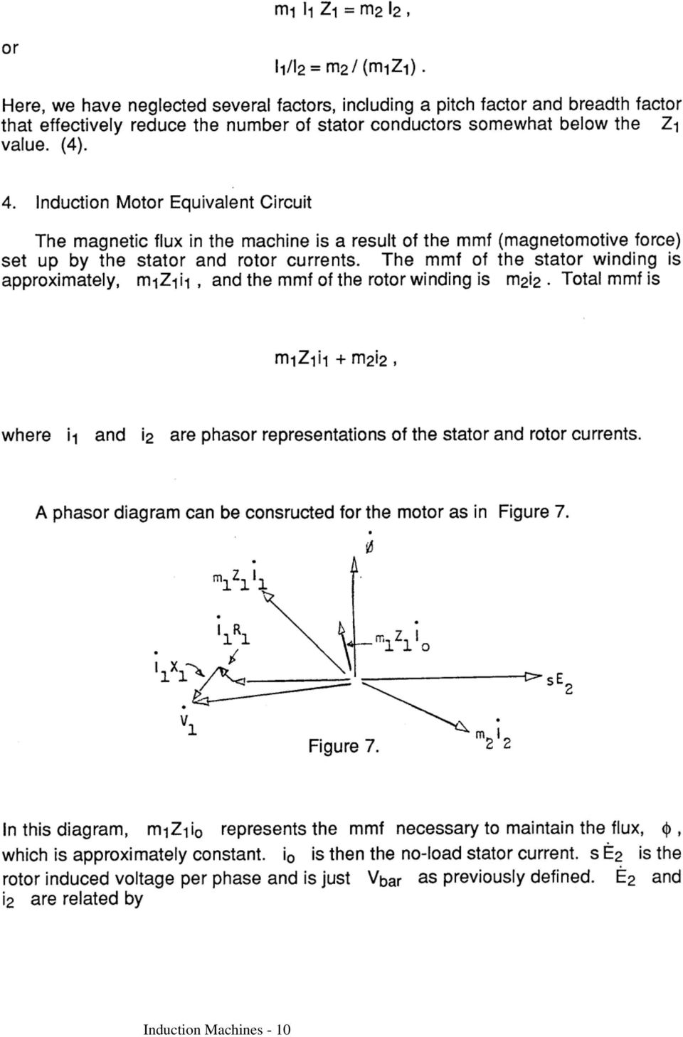
1 THREE-PHASE INDUCTION MOTOR March 2007 A. PREPARATION 1. Introduction 2. The Rotating Field 3. Rotor Currents 4. Induction Motor Equivalent Circuit 5. Torque and Power Characteristics 6. Operation Beyond the Range 0 < s < 1 7. Determination of Motor Constants 8. Bibliography B. EXPERIMENT 1. Equipment List 2. Speed and Direction of Rotation 3. Starting Current 4. No Load Test 5. Locked Rotor Test C. REPORT Induction Machines - 1

2 Induction Machines - 2

3 Induction Machines - 3

4 Induction Machines - 4

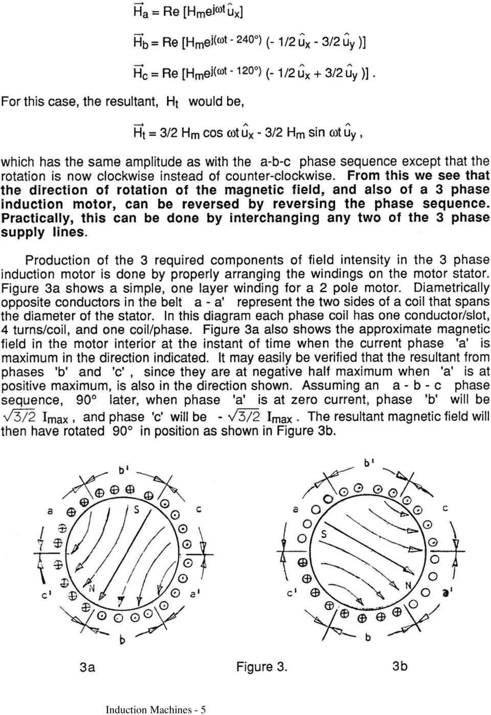
5 Induction Machines - 5
6 Induction Machines - 6

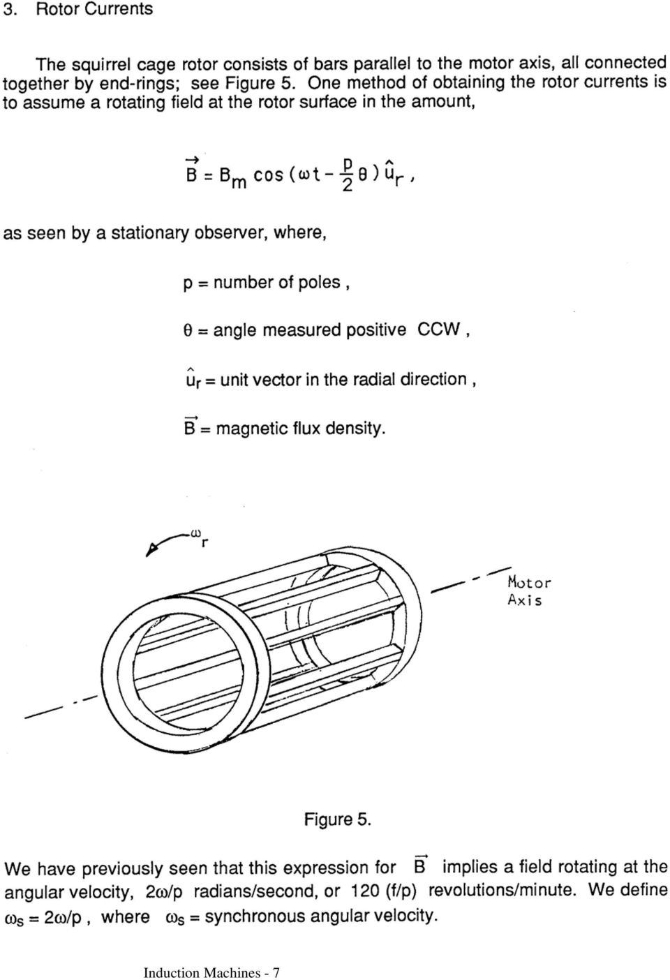
7 Induction Machines - 7
8 Induction Machines - 8

9 Induction Machines - 9

10 Induction Machines - 10
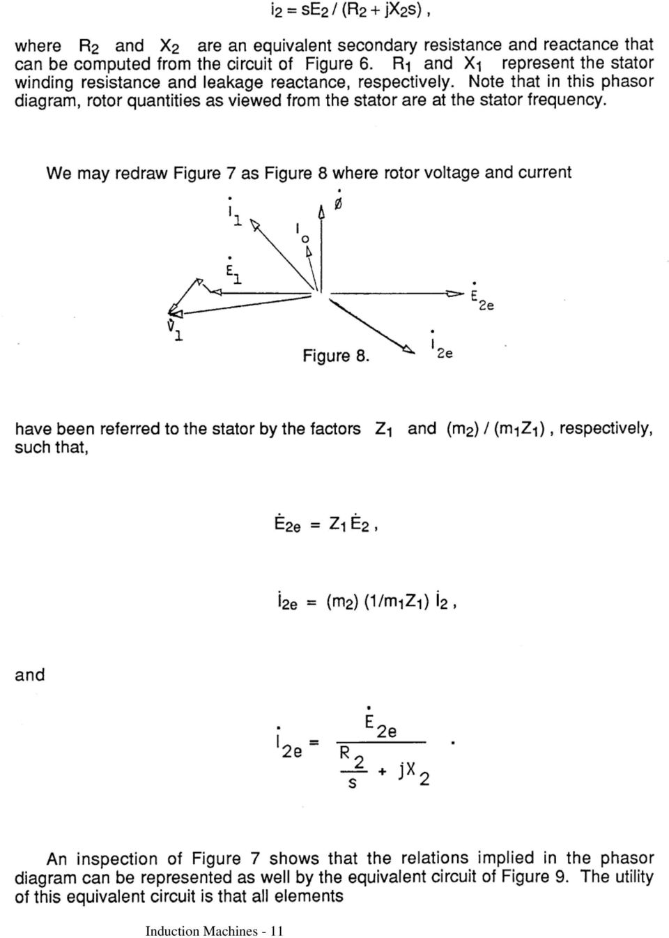
11 Induction Machines - 11
12 Induction Machines - 12

13 Induction Machines - 13

14 Induction Machines - 14

15 Rather than the equivalent circuit of Fig. 10, we choose one more akin to Fig. 9 to yield the result shown in Fig. 13. Based on past experience, the following simplifying assumptions can be made for this model: Induction Machines - 15

16 X 0 >> X 1, R 0 + jx 0 >> R 2 + jx 2, and X 1 X 2. NOTE WELL: This is based upon a WYE model and therefore represents but one of the three phases. For the rotor locked, s = 1 so that the following equations can be written from the equivalent circuit of Figure 13 assuming R 0 + jx 0 >> R 2 + jx 2 : Z 11 = (R 1 + R 2 ) + j(x 1 + X 2 ), Z 11 = V 1 /I 1, and P PH = (R 1 + R 2 )I 1 2 These equations can be solved for R2, X 1, and X 2 as follows: R 2 = (P PH /I 1 2 ) R 1 and (by assumption) X 1 = X 2 = ½ Z 11 2 (R 1 + R 2 ) 2. Assuming that the stator resistance R 1 is measured at DC and that phase power P PH, phase voltage V 1, and phase current I 1 are measured, R 2, X 1, and X 2 can be calculated for the motor from the locked rotor test data. From the data obtained from the no-load test, we can determine the values for the series circuit elements R 0 and X 0. To find these values, we draw graphs of power and line current versus applied voltage as shown in Figure 14. First the measured I 1 and the measured phase power P PH are used to calculate P C + P FW = P PH I 1 2 R 1, where I 1 2 R 1 is the copper loss in this no-load case, P C [W] is the per-phase core loss and P FW [W] is the per-phase friction-and-windage. The derived values are then appropriately plotted and a suitable approximating curve put through them; this curve is then cleverly extrapolated backwards to the voltage origin, and because core loss varies as V 1 α, its intercept gives the friction-and-windage power loss. This will be explored further on the next page. The observant student will note the italicized and bold-face material in this sentence and realize that brainpower may be more important than computer power in getting this right. Induction Machines - 16

17 Figure 14 For no load, s = 0 so that the following equations can be written from the equivalent circuit of Figure 13: Z IN = (R 1 + R 0 ) + j(x 1 + X 0 ) Z IN = V 1 /I 1. P PH = P Cu + P C + P FW = I 1 2 (R 1 + R 0 ) + P FW. Thus: R 0 = [P PH P FW ]/I R 1 X 0 = Z IN 2 (R 1 + R 0 ) 2 X 1. Assuming that phase power P PH, phase voltage V 1, and phase current I 1 are measured and that friction-and-windage loss P FW has been obtained as shown in Figure 14, R 0 and X 0 can also be calculated for the motor from the no-load test data. 8. Bibliography (1) A.S. Langsdorf, Theory of Alternating Current Machinery, 2nd. ed., New York, McGraw- Hill, (2) T.S. Reynolds and T. Bernstein, "The Damnable Alternating Current", Proceedings of IEEE, (64) pgs , Sept (3) P.L. Alger and R.E. Arnold, "The History of Induction Motors in America", Proceedings of IEEE, (64), pgs , Sept Induction Machines - 17
 A.S. Langsdorf, Theory of Alternating Current Machinery, 2nd. ed., New York, McGraw- Hill, 1955. (2) T.S. Reynolds and T.")
18 B. EXPERIMENT 1. Equipment List One Instrumentation Rack with the usual test equipment One 208 Volt, 0.75 HP, 3-phase induction motor One dynamometer with torque controller One Phase Sequence Indicator One single-phase wattmeter plus miscellaneous apparatus as needed 2. Initial Data Record all nameplate information for the induction motor. You should also make a DC measurement of stator winding line-to-line resistance using a DMM. 3. Speed and Direction of Rotation The motor is mounted in a test rig that allows one to control the torque applied to the motor shaft and to measure both rpm and torque. The rpm sensor operates on a Hall effect principle and consists of a disk bearing on its periphery two magnetic pole-pairs and a detector that pulses once each time a pole-pair is rotated past it. Observe that, by counting the output of the detector, you will get a frequency, φ [Hz], that is twice the actual rotational frequency of the motor. Therefore motor rpm = n = 60 (½φ) = 30φ. To observe the rpm sensor in operation, proceed as follows. Energize the detector with 20 VDC ; and attach its output to the oscilloscope, the torque controller, and frequency counter. Power up the motor normally and determine the no-load * rpm when the motor, as viewed from the front, is rotating clockwise (CW); repeat with the motor spinning counter clockwise (CCW). BE CAREFUL!! It can hurt to tangle with a three-phase motor. A successful salesman for General Electric's motor division once remarked to one of your instructors that, when asked by a customer how a motor * The no-load condition is that which obtains when the controller knob is fully counter-clockwise. Induction Machines - 18

19 actually worked, he invariably replied "Very well, indeed.". This attitude is typical of a technologically mature discipline: one really can afford to treat the device as if it were a black box. Therefore, in addition to determining the short circuit and open circuit characteristics of your motor you will also have to determine its input and output powers. To this end, it will be assumed that the motor is a balanced three phase wye connected load and that you will therefore need to measure only one line-neutral voltage, only one line current, and only one phase power to characterize P in completely. That is, P in = 3P line-neutral = 3P phase = 3I rms V rms cosθ. Take note that V rms is the phase voltage V line-neutral = V line-line / 3. Further, P out = 2πfT = 2πn 60 T = πφt, where T is the shaft torque, measured with the dynamometer in-oz, which must be converted to N. m in order to obtain power in watts. 4. Starting Current Wire up the motor for CW motion so that starting current can be measured accurately using the oscilloscope #. With no load on the motor and 120 V rms, lineline, turn on the power and observe and record the transient starting current &. 5. No Load Test. Precisely 1 h after the scheduled start of the lab, you must be prepared to measure V rms and φ(v rms ), I rms (V rms ), P phase (V rms ). Because there is no way to control V rms at the bench, all lab groups are required to take their measurements in synchrony as the line-line voltage is varied at the control panel by the instructor. Line-to-line voltage will be varied from 30 to 210 V in steps of 30 V. 6. Locked Rotor Test. This portion of the experiment will begin immediately after the NO Load Test is complete. With the motor de-energized, lock the rotor with the wooden clamp-on fixture provided. Turn on the power. Note that V rms will initially be low, # Remember that you are working with polyphase power. Therefore it will be essential for you to distinguish carefully between line-line and line-neutral voltages. & Just how this is done is up to you. But it can be done. It just can t be done swiftly unless you design your measurement in advance. Induction Machines - 19

20 and the instructor will then raise it in steps until I rms (V rms ) = I full-load. Measure V rms and φ(v rms ), I rms (V rms ), P phase (V rms ). Turn off the power. 7. Torque vs. Speed Curves. Immediately after the Locked Rotor Test is complete, the instructor will reset the line-to-line voltage to approximately 120 V rms. The dynamometer is a device that allows placing a variable load on the motor. Use the weights provided, and vary the control current to the dynamometer so that the motor will be loaded with a torque roughly proportional to the control current. This control current is feedback regulated by the output from the rpm sensor, but only if you run the necessary coax: should you omit this coax, your data will be subtly degraded. Since the product of motor torque (T) and shaft angular velocity (πφ) is power, the dynamometer is absorbing energy. This energy is dissipated primarily as heat, and the dynamometer temperature will therefore rise. It is advisable to feel the dynamometer case occasionally to insure that it is not overheating. Note that the torque exerted upon the motor by the dynamometer is indicated by the appropriate scale on the dynamometer circumference. In using the dynamometer, care should be taken (i) to avoid sudden substantial variations of control current and (ii) to avoid sudden motor starts with the control current on. These can slam the dynamometer against its limit stops. Treat the dynamometer as the sensitive instrument that it is. Complete the experiment as follows. First, begin at no load and, by gradually increasing the dynamometer control current, measure φ, P phase (φ), T(φ), and I(φ) as φ gradually decreases. Continue this until you reach rated current. The motor should not stall #. However, if it does stall, quickly reduce the dynamometer current to restart the motor. # Win laurels! Improve your grade! The instructors have a nagging suspicion that these induction motors have a pull-up torque. But, in the entire history of the course, no one has ever been able to detect one. Solve this mystery and garner esteem. Induction Machines - 20

21 C. REPORT (a) Based on your data from the no-load and locked-rotor tests, do the following. Plot graphs similar to those described in Figure 14 and find the power lost due to friction and windage. Compute the following: (1) the stator winding phase resistance R 1 from your line-to-line measurement, (2) numerical values of the exciting path elements R o and X o at rated voltage, and (3) numerical values of R 2 and X 1 and X 2 at rated current. Assume that X 1 is equal to X 2. Show your final equivalent circuit (Figure 13) for the induction motor using these values, (b) Use your equivalent circuit to calculate the expected starting current of the motor assuming 120 V rms, line-line and no load. Is your calculated value close to the observed value? Comment. [Note: You will have to study Fig. 13 and Section 7 with care to answer this question successfully.] (c) Use your equivalent circuit to generate smooth theoretical curves of slip (%), torque (ft-lbs), power in (watts), power out (Hp), efficiency (%), line current (Amp), and power factor versus motor speed (rpm). All of these parameters are to be computed at 120 V rms, line-line and six separate graphs are to be made using the same motor speed scale. Next, overlay the experimental points onto these graphs and comment cogently. (d) Using your equivalent circuit, compute the motor horsepower at rated line-to-line voltage of 208V and rated speed. Compare your result with the 0.75 Hp given as the rated output on the motor nameplate. Is 0.75 Hp a conservative value for this motor? Induction Machines - 21
Equipment: Power Supply, DAI, Wound rotor induction motor (8231), Electrodynamometer (8960), timing belt.
, Electrodynamometer (8960), timing belt.") Lab 13: Wound rotor induction motor. Objective: to examine the construction of a 3-phase wound rotor induction motor; to understand exciting current, synchronous speed and slip in this motor; to determine
Lab 13: Wound rotor induction motor. Objective: to examine the construction of a 3-phase wound rotor induction motor; to understand exciting current, synchronous speed and slip in this motor; to determine
Equipment: Power Supply, DAI, Synchronous motor (8241), Electrodynamometer (8960), Tachometer, Timing belt.
, Electrodynamometer (8960), Tachometer, Timing belt.") Lab 9: Synchronous motor. Objective: to examine the design of a 3-phase synchronous motor; to learn how to connect it; to obtain its starting characteristic; to determine the full-load characteristic of
Lab 9: Synchronous motor. Objective: to examine the design of a 3-phase synchronous motor; to learn how to connect it; to obtain its starting characteristic; to determine the full-load characteristic of
Induction Motor Theory
 PDHonline Course E176 (3 PDH) Induction Motor Theory Instructor: Jerry R. Bednarczyk, P.E. 2012 PDH Online PDH Center 5272 Meadow Estates Drive Fairfax, VA 22030-6658 Phone & Fax: 703-988-0088 www.pdhonline.org
INDUCTION MOTOR PERFORMANCE TESTING WITH AN INVERTER POWER SUPPLY, PART 2
 INDUCTION MOTOR PERFORMANCE TESTING WITH AN INVERTER POWER SUPPLY, PART 2 By: R.C. Zowarka T.J. Hotz J.R. Uglum H.E. Jordan 13th Electromagnetic Launch Technology Symposium, Potsdam (Berlin), Germany,
Unit 33 Three-Phase Motors
 Unit 33 Three-Phase Motors Objectives: Discuss the operation of wound rotor motors. Discuss the operation of selsyn motors. Discuss the operation of synchronous motors. Determine the direction of rotation
Motors and Generators
 Motors and Generators Electro-mechanical devices: convert electrical energy to mechanical motion/work and vice versa Operate on the coupling between currentcarrying conductors and magnetic fields Governed
NO LOAD & BLOCK ROTOR TEST ON THREE PHASE INDUCTION MOTOR
 INDEX NO. : M-142 TECHNICAL MANUAL FOR NO LOAD & BLOCK ROTOR TEST ON THREE PHASE INDUCTION MOTOR Manufactured by : PREMIER TRADING CORPORATION (An ISO 9001:2000 Certified Company) 212/1, Mansarover Civil
DIRECT CURRENT GENERATORS
 DIRECT CURRENT GENERATORS Revision 12:50 14 Nov 05 INTRODUCTION A generator is a machine that converts mechanical energy into electrical energy by using the principle of magnetic induction. This principle
SYNCHRONOUS MACHINES
 SYNCHRONOUS MACHINES The geometry of a synchronous machine is quite similar to that of the induction machine. The stator core and windings of a three-phase synchronous machine are practically identical
Equipment: Power Supply, DAI, Universal motor (8254), Electrodynamometer (8960), timing belt.
, Electrodynamometer (8960), timing belt.") Lab 12: The universal motor. Objective: to examine the construction of the universal motor; to determine its no-load and full-load characteristics while operating on AC; to determine its no-load and full-load
Lab 12: The universal motor. Objective: to examine the construction of the universal motor; to determine its no-load and full-load characteristics while operating on AC; to determine its no-load and full-load
Introduction. Three-phase induction motors are the most common and frequently encountered machines in industry
 Induction Motors Introduction Three-phase induction motors are the most common and frequently encountered machines in industry - simple design, rugged, low-price, easy maintenance - wide range of power
Lab 8: DC generators: shunt, series, and compounded.
 Lab 8: DC generators: shunt, series, and compounded. Objective: to study the properties of DC generators under no-load and full-load conditions; to learn how to connect these generators; to obtain their
Application Information
 Moog Components Group manufactures a comprehensive line of brush-type and brushless motors, as well as brushless controllers. The purpose of this document is to provide a guide for the selection and application
INDUCTION REGULATOR. Objective:
 INDUCTION REGULATOR Objective: Using a wound rotor induction motor an Induction Regulator, study the effect of rotor position on the output voltage of the regulator. Also study its behaviour under load
IV. Three-Phase Induction Machines. Induction Machines
 IV. Three-Phase Induction Machines Induction Machines 1 2 3 4 5 6 7 8 9 10 11 12 13 Example 1: A 480V, 60 Hz, 6-pole, three-phase, delta-connected induction motor has the following parameters: R 1 =0.461
Three-Phase Induction Motor
 EXPERIMENT Induction motor Three-Phase Induction Motors 208V LL OBJECTIVE This experiment demonstrates the performance of squirrel-cage induction motors and the method for deriving electrical equivalent
Prof. Krishna Vasudevan, Prof. G. Sridhara Rao, Prof. P. Sasidhara Rao
 6 Synchronous motor 6.1 Principle of operation In order to understand the principle of operation of a synchronous motor, let us examine what happens if we connect the armature winding (laid out in the
SYNCHRONOUS MACHINE TESTING WITH MOTOR CIRCUIT ANALYSIS INSTRUMENTATION
 SYNCHRONOUS MACHINE TESTING WITH MOTOR CIRCUIT ANALYSIS INSTRUMENTATION Introduction Howard W. Penrose, Ph.D., CMRP Vice President, Engineering and Reliability Services Dreisilker Electric Motors, Inc.
Lab 14: 3-phase alternator.
 Lab 14: 3-phase alternator. Objective: to obtain the no-load saturation curve of the alternator; to determine the voltage regulation characteristic of the alternator with resistive, capacitive, and inductive
AUTOMATED, FULL LOAD MOTOR TESTING AT PRODUCTION SPEEDS
 AUTOMATED, FULL LOAD MOTOR TESTING AT PRODUCTION SPEEDS Abstract: Revolutionary test method coupled with innovative automation yields superior motor performance measurement data without sacrifice of production
SECTION 4 ELECTRIC MOTORS UNIT 17: TYPES OF ELECTRIC MOTORS
 SECTION 4 ELECTRIC MOTORS UNIT 17: TYPES OF ELECTRIC MOTORS UNIT OBJECTIVES After studying this unit, the reader should be able to Describe the different types of open single-phase motors used to drive
How to Turn an AC Induction Motor Into a DC Motor (A Matter of Perspective) Steve Bowling Application Segments Engineer Microchip Technology, Inc.
 Steve Bowling Application Segments Engineer Microchip Technology, Inc.") 1 How to Turn an AC Induction Motor Into a DC Motor (A Matter of Perspective) Steve Bowling Application Segments Engineer Microchip Technology, Inc. The territory of high-performance motor control has
1 How to Turn an AC Induction Motor Into a DC Motor (A Matter of Perspective) Steve Bowling Application Segments Engineer Microchip Technology, Inc. The territory of high-performance motor control has
Motor Fundamentals. DC Motor
 Motor Fundamentals Before we can examine the function of a drive, we must understand the basic operation of the motor. It is used to convert the electrical energy, supplied by the controller, to mechanical
Speed Control Methods of Various Types of Speed Control Motors. Kazuya SHIRAHATA
 Speed Control Methods of Various Types of Speed Control Motors Kazuya SHIRAHATA Oriental Motor Co., Ltd. offers a wide variety of speed control motors. Our speed control motor packages include the motor,
Introduction. Upon completion of Basics of AC Motors you should be able to:
 Table of Contents Introduction...2 AC Motors...4 Force and Motion...6 AC Motor Construction... 12 Magnetism... 17 Electromagnetism... 19 Developing a Rotating Magnetic Field...24 Rotor Rotation...29 Motor
AC generator theory. Resources and methods for learning about these subjects (list a few here, in preparation for your research):
:") AC generator theory This worksheet and all related files are licensed under the Creative Commons Attribution License, version 1.0. To view a copy of this license, visit http://creativecommons.org/licenses/by/1.0/,
AC generator theory This worksheet and all related files are licensed under the Creative Commons Attribution License, version 1.0. To view a copy of this license, visit http://creativecommons.org/licenses/by/1.0/,
GE Industrial Systems. AC Motor Selection and Application Guide
 apple GE Industrial Systems AC Motor Selection and Application Guide TABLE OF CONTENTS Voltage... 2 Frequency... 3 Phase... 4 Motor Output Rating... 4 Polyphase Motors... 4 Single-phase Motors... 4 Service
3-Phase AC Calculations Revisited
 AN110 Dataforth Corporation Page 1 of 6 DID YOU KNOW? Nikola Tesla (1856-1943) came to the United States in 1884 from Yugosiavia. He arrived during the battle of the currents between Thomas Edison, who
Variable Transformers Product Design & Engineering Data
 Variable Transformers Product Design & Engineering Data Product Design & Engineering Data Type 1010B Cutaway General Information STACO ENERGY PRODUCTS CO. is a leading manufacturer of variable transformers,
C Standard AC Motors
 C Standard AC Standard AC C-1 Overview, Product Series... C-2 Constant... C-9 C-21 C-113 Reversible C-147 Overview, Product Series Constant Reversible Electromagnetic Brake C-155 Electromagnetic Brake
How the efficiency of induction motor is measured?
 How the efficiency of induction motor is measured? S. Corino E. Romero L.F. Mantilla Department of Electrical Engineering and Energy E.T.S.I.I. y T. Universidad de Cantabria Avda de Los Castros, 395 Santander
ET 332b Ac Electric Machines and Power Systems
 Instructor: Dr. Carl Spezia, PE Office: Engr. D110 Phone: 453-7839 E-mail: [email protected] ET 332b Ac Electric Machines and Power Systems Office Hours: 9:00 am - 10:00 am M-W-F 2:00 pm - 3:00 pm M-W-F
Synchronous motor. Type. Non-excited motors
 Synchronous motor A synchronous electric motor is an AC motor in which the rotation rate of the shaft is synchronized with the frequency of the AC supply current; the rotation period is exactly equal to
Permanent Magnet Motor Kit, Magnetic Reed Type. (SKY-ReedMotorKit) Instructions
 Instructions") Permanent Magnet Motor Kit, Magnetic Reed Type (SKY-ReedMotorKit) Instructions This kit contains powerful permanent magnets. Exercise caution when handling them as they can pull on iron tools and snap
Permanent Magnet Motor Kit, Magnetic Reed Type (SKY-ReedMotorKit) Instructions This kit contains powerful permanent magnets. Exercise caution when handling them as they can pull on iron tools and snap
Electric Motors and Drives
 EML 2322L MAE Design and Manufacturing Laboratory Electric Motors and Drives To calculate the peak power and torque produced by an electric motor, you will need to know the following: Motor supply voltage,
Equipment: Power Supply, DAI, Transformer (8341), Variable resistance (8311), Variable inductance (8321), Variable capacitance (8331)
, Variable resistance (8311), Variable inductance (8321), Variable capacitance (8331)") Lab 5: Single-phase transformer operations. Objective: to examine the design of single-phase transformers; to study the voltage and current ratios of transformers; to study the voltage regulation of the
Lab 5: Single-phase transformer operations. Objective: to examine the design of single-phase transformers; to study the voltage and current ratios of transformers; to study the voltage regulation of the
Three-phase AC circuits
 Three-phase AC circuits This worksheet and all related files are licensed under the Creative Commons Attribution License, version 1.0. To view a copy of this license, visit http://creativecommons.org/licenses/by/1.0/,
Direct Current Motors
 Direct Current Motors DC MOTORS The DC machine can operate as a generator and as a motor. Chap 5. Electrical Machines by Wildi, 6 e Lecturer: R. Alba-Flores Alfred State College Spring 2008 When a DC machine
Basics of Electricity
 Basics of Electricity Generator Theory PJM State & Member Training Dept. PJM 2014 8/6/2013 Objectives The student will be able to: Describe the process of electromagnetic induction Identify the major components
How to Optimize Performance and Minimize Size in High Speed Applications High Performance Brushless DC Motors
 thinkmotion How to Optimize Performance and Minimize Size in High Speed Applications High Performance Brushless DC Motors I. Introduction II. III. IV. Optimization of a Brushless DC motor for high speed
Solution: Angular velocity in consistent units (Table 8.1): 753.8. Velocity of a point on the disk: Rate at which bits pass by the read/write head:
: 753.8. Velocity of a point on the disk: Rate at which bits pass by the read/write head:") Problem P8: The disk in a computer hard drive spins at 7200 rpm At the radius of 0 mm, a stream of data is magnetically written on the disk, and the spacing between data bits is 25 μm Determine the number
Problem P8: The disk in a computer hard drive spins at 7200 rpm At the radius of 0 mm, a stream of data is magnetically written on the disk, and the spacing between data bits is 25 μm Determine the number
GE Industrial Systems. AC Motor Selection and Application Guide
 apple GE Industrial Systems AC Motor Selection and Application Guide TABLE OF CONTENTS Voltage... 2 Frequency... 3 Phase... 4 Motor Output Rating... 4 Polyphase Motors... 6 Single-phase Motors... 9 Service
UNIVERSITY OF WATERLOO ELECTRICAL & COMPUTER ENGINEERING DEPARTMENT ME269 ELECTROMECHANICAL DEVICES AND POWER PROCESSING.
 UNIVERSITY OF WATERLOO ELECTRICAL & COMPUTER ENGINEERING DEPARTMENT ME269 ELECTROMECHANICAL DEVICES AND POWER PROCESSING. Group # First Name Last Name UserID @uwaterloo.ca Experiment #3: DIRECT CURRENT
FREQUENCY CONTROLLED AC MOTOR DRIVE
 FREQUENCY CONTROLLED AC MOTOR DRIVE 1.0 Features of Standard AC Motors The squirrel cage induction motor is the electrical motor motor type most widely used in industry. This leading position results mainly
Technical Guide No. 100. High Performance Drives -- speed and torque regulation
 Technical Guide No. 100 High Performance Drives -- speed and torque regulation Process Regulator Speed Regulator Torque Regulator Process Technical Guide: The illustrations, charts and examples given in
Modelling, Simulation and Performance Analysis of A Variable Frequency Drive in Speed Control Of Induction Motor
 International Journal of Engineering Inventions e-issn: 78-7461, p-issn: 319-6491 Volume 3, Issue 5 (December 013) PP: 36-41 Modelling, Simulation and Performance Analysis of A Variable Frequency Drive
2. A conductor of length 2m moves at 4m/s at 30 to a uniform magnetic field of 0.1T. Which one of the following gives the e.m.f. generated?
 Extra Questions - 2 1. A straight length of wire moves through a uniform magnetic field. The e.m.f. produced across the ends of the wire will be maximum if it moves: a) along the lines of magnetic flux
8 Speed control of Induction Machines
 8 Speed control of Induction Machines We have seen the speed torque characteristic of the machine. In the stable region of operation in the motoring mode, the curve is rather steep and goes from zero torque
MDC151-024031 Series
 MDC151-024031 Series 24V, 3A Brushless DC Controller User s Guide A N A H E I M A U T O M A T I O N 910 East Orangefair Lane, Anaheim, CA 92801 e-mail: [email protected] (714) 992-6990 fax: (714)
Evaluating Induction Motor Rotor Bars with Electrical Signature Analysis
 Evaluating Induction Motor Rotor Bars with Electrical Signature Analysis Howard W Penrose, Ph.D., CMRP SUCCESS by DESIGN Reliability Services Hello and welcome to our presentation on Evaluating Induction
Application for Small Generator Facility Interconnection Tier 2, Tier 3 or Tier 4 Interconnection
 Application for Small Generator Facility Interconnection Tier 2, Tier 3 or Tier 4 Interconnection (See ARSD chapter 20:10:36 for the requirements for a Tier 2, Tier 3, or Tier 4 Interconnection.) Applicant/Interconnection
Lab E1: Introduction to Circuits
 E1.1 Lab E1: Introduction to Circuits The purpose of the this lab is to introduce you to some basic instrumentation used in electrical circuits. You will learn to use a DC power supply, a digital multimeter
PowerFlex Dynamic Braking Resistor Calculator
 Application Technique PowerFlex Dynamic Braking Resistor Calculator Catalog Numbers 20A, 20B, 20F, 20G, 22A, 22B Important User Information Solid-state equipment has operational characteristics differing
Tips For Selecting DC Motors For Your Mobile Robot
 Tips For Selecting DC Motors For Your Mobile Robot By AJ Neal When building a mobile robot, selecting the drive motors is one of the most important decisions you will make. It is a perfect example of an
How To Measure Power Of A Permanent Magnet Synchronous Motor
 Freescale Semiconductor Document Number:AN4680 Application Note Rev. 0, 02/2013 PMSM Electrical Parameters Measurement by: Viktor Bobek 1 Introduction The vector control, also known as the field-oriented
22.302 Experiment 5. Strain Gage Measurements
 22.302 Experiment 5 Strain Gage Measurements Introduction The design of components for many engineering systems is based on the application of theoretical models. The accuracy of these models can be verified
Topics to cover: 1. Structures and Drive Circuits 2. Equivalent Circuit. Introduction
 Chapter 12. Brushless DC Motors Topics to cover: 1. Structures and Drive Circuits 2. Equivalent Circuit 3. Performance 4. Applications Introduction Conventional dc motors are highly efficient and their
Principles of Adjustable Frequency Drives
 What is an Adjustable Frequency Drive? An adjustable frequency drive is a system for controlling the speed of an AC motor by controlling the frequency of the power supplied to the motor. A basic adjustable
TERMINAL MARKINGS AND CONNECTIONS PART WINDING START
 TERMINAL MARKINGS AND CONNECTIONS PART WINDING START NEMA NOMENCLATURE 6 LEADS 7 7 3 9 8 Delta 3 9 8 Wye OPER. 9 MODE L L L3 OPEN 7 START 3 7,8,9 T T T3 T7 T8 T9 RUN,7,8 3,9 3 8 MOTOR LEADS 3 7 Double
How To Wire A Three Phase, Single Phase, Wye Transformer
 Three-Phase Transformers When more power is needed - three transformers can be tied together. This is called three-phase. Here s a simple way of comparing single-phase to threephase power. Single-Phase
Rotary Phase Converters
 FACTS from Ronk Electrical Industries, Inc. Bulletin 11981 Rotary Phase Converters ROTOVERTER Pat. No. 3,670,238 ROTO-CON Pat. No. 4,158,225 What are the ROTO-CON and ROTOVERTER power converters? The ROTO-CON
PHASE CONVERSION TECHNOLOGY OVERVIEW
 Dr. Larry Meiners, Ph.D. PHASE CONVERSION TECHNOLOGY OVERVIEW Introduction A wide variety of commercial and industrial electrical equipment requires three-phase power. Electric utilities do not install
Brush DC Motor Basics. by Simon Pata Business Unit Manager, Brushless DC
 thinkmotion Brush DC Motor Basics by Simon Pata Business Unit Manager, Brushless DC Ironless DC Motor Basics Technical Note Brushed DC ironless motors are found in a large variety of products and applications
The DC Motor. Physics 1051 Laboratory #5 The DC Motor
 The DC Motor Physics 1051 Laboratory #5 The DC Motor Contents Part I: Objective Part II: Introduction Magnetic Force Right Hand Rule Force on a Loop Magnetic Dipole Moment Torque Part II: Predictions Force
VARIABLE FREQUENCY DRIVES THEORY, APPLICATION, AND TROUBLESHOOTING
 VARIABLE FREQUENCY DRIVES THEORY, APPLICATION, AND TROUBLESHOOTING BY HOWARD W. PENROSE UNIVERSITY OF ILLINOIS AT CHICAGO ENERGY RESOURCES CENTER 851 SOUTH MORGAN STREET ROOM 1213, SEO, MC156 CHICAGO,
Electric Motor Brake Horsepower Calculations
 Electric Motor Brake Horsepower Calculations By Norm Christopherson These motor calculations are contained here as they apply to the changing conditions of the blower motor when pulley adjustments are
Servo Info and Centering
 Info and Centering A servo is a mechanical motorized device that can be instructed to move the output shaft attached to a servo wheel or arm to a specified position. Inside the servo box is a DC motor
What Is Regeneration?
 What Is Regeneration? Braking / Regeneration Manual Regeneration Overview Revision 1.0 When the rotor of an induction motor turns slower than the speed set by the applied frequency, the motor is transforming
D.C. Motors. Products and specifications subject to change without notice.
 D.C. Motors Order/Technical Support - Tel: (8) 677-5 / FAX: (8) 677-865 / www.crouzet-usa.com / DC Motors Selection guide Gearbox Speed Torque max (Nm).5. Type of Gearbox 8 8 8. Power usable (w) Torque
SX460. Generator Automatic Voltage Regulator Operation Manual
 SX460 Generator Automatic Voltage Regulator Operation Manual Self Excited Automatic Voltage Regulator Compatible with Newage SX460* * Use for reference purpose only and not a genuine Newage product. 1.
Offshore Platform Powered With New Electrical Motor Drive System
 Offshore Platform Powered With New Electrical Motor Drive System Authors: Jan O. Lamell, M.Sc E.E. ABB Automation Technologies Presenters: Thomas Johansson, M.Sc E.E. ABB Automation Technologies Timothy
AC Generators and Motors
 AC Generators and Motors Course No: E03-008 Credit: 3 PDH A. Bhatia Continuing Education and Development, Inc. 9 Greyridge Farm Court Stony Point, NY 10980 P: (877) 322-5800 F: (877) 322-4774 [email protected]
Power Electronics. Prof. K. Gopakumar. Centre for Electronics Design and Technology. Indian Institute of Science, Bangalore.
 Power Electronics Prof. K. Gopakumar Centre for Electronics Design and Technology Indian Institute of Science, Bangalore Lecture - 1 Electric Drive Today, we will start with the topic on industrial drive
Introduction to Linear Actuators: Precision Linear Motion Accomplished Easily and Economically
 Introduction to Linear Actuators: Precision Linear Motion Accomplished Easily and Economically Part 1 of 2 When students are trained in classic mechanical engineering, they are taught to construct a system
Simple Analysis for Brushless DC Motors Case Study: Razor Scooter Wheel Motor
 Simple Analysis for Brushless DC Motors Case Study: Razor Scooter Wheel Motor At first glance, a brushless direct-current (BLDC) motor might seem more complicated than a permanent magnet brushed DC motor,
Drive circuit basics + V. τ e. Industrial Circuits Application Note. Winding resistance and inductance
 ndustrial Circuits Application Note Drive circuit basics For a given size of a stepper motor, a limited space is available for the windings. n the process of optimizing a stepper motor drive system, an
..OR How To Protect your 3-Phase Equipment Investment with 3-Phase Monitors from Time Mark...
 ..OR How To Protect your 3-Phase Equipment Investment with 3-Phase Monitors from Time Mark... TIME MARK CORPORATION 11440 EAST PINE STREET TULSA, OK 74116 USA tel 918 438-1220 fax 918 437-7584 www.time-mark.com
AC Motor Speed. n s = synchronous speed (in RPM), f = frequency (in Hz), and p = the number of poles
, f = frequency (in Hz), and p = the number of poles") AC Induction Motors Simplest and most rugged electric motor Consists of wound stator and rotor assembly AC in the primary member (stator) induces current in the secondary member (rotor) Combined electromagnetic
AC Induction Motors Simplest and most rugged electric motor Consists of wound stator and rotor assembly AC in the primary member (stator) induces current in the secondary member (rotor) Combined electromagnetic
DHANALAKSHMI COLLEGE OF ENGINEERING DEPARTMENT OF ELECTRICAL AND ELECTRONICS ENGINEERING EE2302 - ELECTRICAL MACHINES II UNIT-I SYNCHRONOUS GENERATOR
 1 DHANALAKSHMI COLLEGE OF ENGINEERING DEPARTMENT OF ELECTRICAL AND ELECTRONICS ENGINEERING Constructional details Types of rotors EE2302 - ELECTRICAL MACHINES II UNIT-I SYNCHRONOUS GENERATOR PART A 1.
Ampere's Law. Introduction. times the current enclosed in that loop: Ampere's Law states that the line integral of B and dl over a closed path is 0
 1 Ampere's Law Purpose: To investigate Ampere's Law by measuring how magnetic field varies over a closed path; to examine how magnetic field depends upon current. Apparatus: Solenoid and path integral
How To Understand And Understand The Electrical Power System
 DOE-HDBK-1011/4-92 JUNE 1992 DOE FUNDAMENTALS HANDBOOK ELECTRICAL SCIENCE Volume 4 of 4 U.S. Department of Energy Washington, D.C. 20585 FSC-6910 Distribution Statement A. Approved for public release;
GENERATOR SELECTION. a. Three phase - 120/208V, 3 phase, 4W wye; 277/408, 3 phase, 4W wye; * 120/240V 3 phase, 4W Delta
 GENERATOR SELECTION Generators must be sized to handle their load based on the continuous KW, kilowatt load, and KVA, kilovoltamp load, and the worst case starting load KW + KVA. They must be derated for
Physical Address: City: State: Zip Code:
 Application for Small Generator Facility Interconnection Tier 2, Tier 3 or Tier 4 Interconnection (For Small Generator Facilities with Electric Nameplate Capacities of 10 MW and less) Applicant Contact
5. Measurement of a magnetic field
 H 5. Measurement of a magnetic field 5.1 Introduction Magnetic fields play an important role in physics and engineering. In this experiment, three different methods are examined for the measurement of
AC-Synchronous Generator
 Design Description AC Generators come in two basic types synchronous and non-synchronous. Synchronous generators lock in with the fundamental line frequency and rotate at a synchronous speed related to
Chen. Vibration Motor. Application note
 Vibration Motor Application note Yangyi Chen April 4 th, 2013 1 Table of Contents Pages Executive Summary ---------------------------------------------------------------------------------------- 1 1. Table
= V peak 2 = 0.707V peak
 BASIC ELECTRONICS - RECTIFICATION AND FILTERING PURPOSE Suppose that you wanted to build a simple DC electronic power supply, which operated off of an AC input (e.g., something you might plug into a standard
BOWL ASSEMBLY SELECTION Select impeller in exactly the same manner as for lineshaft type pump. Note comments under WELL SIZE.
 SUBMERSIBLE PUMP selection A submersible pump consists of the following basic elements: < Bowl Assembly < Motor < Cable < Drop Pipe < Surface Plate (with)(without) discharge elbow DATA REQUIRED FOR SELECTION
Mathematical Modeling and Dynamic Simulation of a Class of Drive Systems with Permanent Magnet Synchronous Motors
 Applied and Computational Mechanics 3 (2009) 331 338 Mathematical Modeling and Dynamic Simulation of a Class of Drive Systems with Permanent Magnet Synchronous Motors M. Mikhov a, a Faculty of Automatics,
DETERMINING ELECTRIC MOTOR LOAD AND EFFICIENCY
 F A C T S H E E T a Program of the U.S. Department of Energy DETERMINING ELECTRIC MOTOR LOAD AND EFFICIENCY Most likely your operation s motors account for a large part of your monthly electric bill. Far
Torque and Rotary Motion
 Torque and Rotary Motion Name Partner Introduction Motion in a circle is a straight-forward extension of linear motion. According to the textbook, all you have to do is replace displacement, velocity,
DC Motor control Reversing
 January 2013 DC Motor control Reversing and a "Rotor" which is the rotating part. Basically there are three types of DC Motor available: - Brushed Motor - Brushless Motor - Stepper Motor DC motors Electrical
INSTALLATION AND MAINTENANCE INSTRUCTIONS FOR THREE PHASE INDUCTION MOTORS
 INSTALLATION AND MAINTENANCE INSTRUCTIONS FOR THREE PHASE INDUCTION MOTORS Frames 143T - 449TZ 5100 North IH 35 Round Rock, Texas 78681 Phone: 800-451-8798 512-255-4141 Fax: 512-244-5512 RECEIVING 1. Check
Inductors in AC Circuits
 Inductors in AC Circuits Name Section Resistors, inductors, and capacitors all have the effect of modifying the size of the current in an AC circuit and the time at which the current reaches its maximum
DC GENERATOR THEORY. LIST the three conditions necessary to induce a voltage into a conductor.
 DC Generators DC generators are widely used to produce a DC voltage. The amount of voltage produced depends on a variety of factors. EO 1.5 LIST the three conditions necessary to induce a voltage into
Chapter 4.5: Electric Motors, Variable Speed Drives
 Short type questions Chapter 4.5: Electric Motors, Variable Speed Drives 1. The resistance of a motor stator winding at 30 C is 0.264 ohms per phase. What will be the resistance of the stator winding per
Power Quality Paper #3
 The Effect of Voltage Dips On Induction Motors by: M D McCulloch 1. INTRODUCTION Voltage depressions caused by faults on the system affect the performance of induction motors, in terms of the production
Electrical Resonance
 Electrical Resonance (R-L-C series circuit) APPARATUS 1. R-L-C Circuit board 2. Signal generator 3. Oscilloscope Tektronix TDS1002 with two sets of leads (see Introduction to the Oscilloscope ) INTRODUCTION
Chapter 11 SERVO VALVES. Fluid Power Circuits and Controls, John S.Cundiff, 2001
 Chapter 11 SERVO VALVES Fluid Power Circuits and Controls, John S.Cundiff, 2001 Servo valves were developed to facilitate the adjustment of fluid flow based on the changes in the load motion. 1 Typical