Fire rated and smoke outlet ductwork
|
|
|
- Georgiana Phyllis Nelson
- 9 years ago
- Views:
Transcription
1 Fire rated and smoke outlet ductwork An industry guide to design and installation Association House, 99 West Street, Farnham, Surrey GU9 7EN t: f: FR&SODUCTWORK Page i

2 FOREWORD I am pleased to have been asked to introduce this new publication from the Association for Specialist Fire Protection. This publication from ASFP should be warmly welcomed by designers, insurers and end-users alike. The prevention of fire spread through ducted systems is of critical importance, as evidenced by a number of recent serious fire losses. This document provides details and gives recommendations not previously covered in other standards or codes of practice and should make a significant contribution to improved fire safety. Contained within the document are sections on the different types of system and their function, information on all the relevant legislation, standards and codes of practice and notes on penetration seals and support systems. BRE particularly recognises the importance of using fire-rated ductwork for air distribution and smoke extraction applications, and is particularly pleased to see these topics addressed here. Our commitment in this area is illustrated by their inclusion in the LPC Design Guide for the Fire Protection of Buildings, the UK insurers' guidance document on building fire protection, which BRE will continue to maintain on their behalf. The merger of BRE and LPC offers exciting new opportunities for working in partnership with ASFP and other experts from the fire industry to promote high standards of fire protection. BRE is sure that this Guide will become an essential reference work within the industry and congratulates ASFP on producing another excellent technical document. Dr Jeremy Hodge Managing Director, Fire and Risk Sciences, BRE FR&SODUCTWORK Page ii

3 Association for Specialist Fire Protection (ASFP) Association House, 99 West Street, Farnham, Surrey GU9 7EN t: +44(0) f: +44(0) The Association was formed in 1976, and currently represents the majority of UK contractors and manufacturers of specialist fire protection products, with associate members representing regulatory, certification, testing and consulting bodies. ASFP seeks to increase awareness and understanding of the nature of fire and the various forms, functions and benefits provided by passive fire protection. It is willing to make available its specialist knowledge on all aspects of fire protection and can assist specifiers and main contractors in identifying products suitable for specific requirements, both in the UK and overseas. ACKNOWLEDGEMENT This document has been prepared by the Fire Rated and Smoke Outlet Ductwork Working Group of the ASFP, and the work of the members of that Committee, as follows, is gratefully acknowledged: R H Earle, Chairman FR&SOD Working Group, Loss Prevention Council; C W Aitken, McCartney Fire Protection Ltd; P W Crewe, Warrington Fire Research Centre; A P Flint, Cape Calsil Systems Ltd (Durasteel); B A James, Fire Protection Ltd; N J MacDonald, Promat Fire Protection Ltd; J E Murray, Senior Hargreaves; N Ralph, Rockwool Ltd; R B Smith, ASFP Technical Officer and B S Webster, Cape Calsil Systems Ltd (Durasteel) Although care has been taken to ensure, to the best of our knowledge, that all data and information contained herein is accurate to the extent that it relates to either matters of fact or accepted practice or matters of opinion at the time of publication, the Association for Specialist Fire Protection accepts no responsibility for any errors in or misinterpretations of such data and/or information or any loss or damage arising from or related to its use. Compliance with this ASFP document does not of itself confer immunity from legal obligation. Association for Specialist Fire Protection 2000 ISBN: FR&SODUCTWORK Page iii

4 CONTENTS 1. INTRODUCTION DEFINITIONS Duct/Ductwork Dampers General TYPES AND FUNCTIONS Mechanical Ventilation Systems Smoke Extraction Systems Dual Ventilation/Smoke Extraction Systems Pressurisation Systems Car Park and Kitchen Extraction Systems REGULATIONS AND CODES Introduction Statutory Instruments Documents Supporting the Statutory Instruments British Standards Institution (BSI) International Organisation of Standardisation (ISO) Draft European Standards HVCA Documents STANDARD FIRE TESTS Fire Resistance Test on Ducts Reaction to Fire Tests FIELD OF APPLICATION FOR FIRE RESISTING DUCTS Field of Direct Application (Ducts Tested to BS 476: Part 24) Extended Application NOTES ON PENETRATION SEALS, SUPPORT SYSTEMS AND ANCILLARY ITEMS Penetration Seals Support Systems Ancillary Items/In-Line Equipment Interface between Fire Rated Ductwork and Elements of Building Construction LIMITATIONS STANDARD SPECIFICATION STANDARD METHOD OF MEASUREMENT OF BUILDING WORKS DATA SHEETS...35 FR&SODUCTWORK Page iv

5 SCOPE This publication is intended to assist the reader in understanding many of the essential details which play a significant part in ensuring that fire rated (which includes smoke outlet) ductwork is correctly designed and installed in accordance with current UK legislative requirements. The information given in this guidance note therefore relates to the types and functions of fire rated ductwork, and references the Building Regulations, British Standards and Codes of Practice which apply to these specific types of duct. Detailed information on current UK standard fire resistance and reaction to fire tests is provided, together with recommended methods for appraisal systems for both direct and extended fields of application. Guidance is also given in respect of the fire resisting requirements for penetration seals, support systems and ancillary items, with a section relating to limitations. Drawings of typical BS 476: Part 24 test constructions are reproduced (by kind permission of the British Standards Institution) and diagrams of types and functions of various fire rated ductwork systems are included. These are for guidance purposes only. The guidance given in this publication specifically refers to fire rated ductwork and does not, therefore, include advice on conventional non-fire rated ventilation ductwork systems. CAUTIONARY NOTE TO ALL DUCTWORK DESIGNERS, MANUFACTURERS AND INSTALLERS Sections of this document emphasise the fact that general purpose ventilation/air conditioning ductwork cannot be utilised as, or converted into, a fire rated ductwork system unless the construction/materials of the whole system are proven by test or assessment in accordance with the requirements of BS 476: Part 24. In this respect the section entitled 'Limitations' will be of particular interest to the reader. FR&SODUCTWORK Page v

6 1. INTRODUCTION This publication has been produced to assist those involved in the specification, installation, inspection and verification of Fire Rated Ductwork and to ensure that minimum performance standards are maintained which will contribute to ensuring that fire compartmentation systems are not breached prematurely. Fire Rated Ductwork can be provided either by specialist companies producing proprietary systems, or by treatment to satisfactorily constructed and supported steel ductwork with the addition of fire insulating materials. Care must be taken when choosing a fire rated ductwork system and checks should be made to ensure that the ductwork fire performance meets with the requirements of the relevant application. Compartment walls and floors will have a prescribed fire resistance period which means that the performance criteria of load-bearing capacity (stability), integrity and insulation have been met for a duration of 30 to 240 minutes. It is therefore vitally important for fire security that where compartmentation boundaries are penetrated by building services, the fire separation and the performance criteria for the penetrated wall or floor are maintained and, in particular, that all forms of ducting in a building should not become a conduit along which fires may spread to other areas. The fire performance of a duct which penetrates a fire resisting/separating element requires careful consideration by specifiers and controlling authorities. The standard periods of stability and integrity should in all cases be at least equal to those required for the penetrated element. Controlling authorities have, in certain circumstances, waived the insulation requirement or allowed a reduced period of insulation (e.g. where they considered that there was no possibility of combustible materials being in the proximity of the ductwork). The guidance given in Approved Document B1 (Means of Escape) and B3 (Internal Fire Spread Structure) of the Building Regulations 1991 for England and Wales refers to BS 5588: Part 9 for alternative ways in which the integrity of compartments may be maintained where ventilation and air conditioning ductwork penetrate fire separating elements. Similar recommendations are given in the Northern Ireland Building Regulations and in the Building Standards (Scotland) Regulations. Many ventilation ductwork systems offer little or no protection against fire spread and therefore, when ventilation ductwork penetrates building compartmentation, the guidance of BS 5588: Part 9 should be followed: i.e. Method 1 Protection using fire dampers; Method 2 Method 3 Protection using fire resisting enclosures; Protection using fire resisting ductwork. Statutory regulations and design codes provide the designer with prescribed periods of fire resistance to construction elements, which give a safe period for evacuation of people, a safe period for fire fighting and also provide for property protection. It is vitally important for life safety that the fire resistance of the construction element is not reduced when ductwork is routed through it. Good practice dictates that fire dampers should not be installed within certain ductwork systems in buildings (e.g. kitchen extraction, staircase and lobby pressurisation, lift shaft ventilation, fresh air make up provision, etc.) therefore either Method 2 or Method 3 of BS 5588 Part 9 should be used. FR&SODUCTWORK Page 1

7 Steel ductwork systems for air movements around buildings are generally constructed to the HVCA guide DW/144 (formerly 142) which is a document covering a wide range of construction standards in the manufacture of sheet metal ductwork for use in low, medium or high pressure applications and includes various methods of jointing, stiffening and supporting of the ductwork. BS 5588: Part 9 paragraph acknowledges that steel ductwork if satisfactorily constructed and supported will be able to provide a high degree of resistance to the passage of smoke and decomposition products. However, rapid transfer of heat through the steel regardless of its thickness prevents the ductwork achieving any degree of fire resistance without supplementary insulation. A satisfactorily constructed and supported steel duct is one proven by test and/or assessment to BS 476: Part 24. An alternative to steel systems is self supporting ductwork such as that constructed from rigid boards. Supplementary insulation may also have to be considered for these systems. In 1987 the British Standards Institution introduced Part 24 of the BS 476 Fire Test series; a method for determination of the fire resistance of ventilation ducts. The document has an annex which gives guidance on the fire performance criteria required for kitchen extract and smoke outlet applications, which differ from the requirements for ventilation ducts. It is therefore vitally important when assessing the suitability of a proposed system of fire rated ductwork that the performance of the proposed system matches the requirements of the application for which it is required; (e.g. a smoke outlet duct is required to maintain a minimum 75% of the original cross section when tested to BS 476: Part 24). It is particularly important, when assessing the suitability of a proposed system of fire rated ductwork, to give due consideration to factors other than fire that may be required. These may include: Seismic qualification of ductwork, support system and penetration sealing method; Pressure/air carrying capacity; Materials sensitive to thermal shock; Acoustic performance requirement of the system; Thermal performance requirement of the system; Resistance to air flow. 2. DEFINITIONS For the purpose of this document the following definitions apply. 2.1 Duct/Ductwork Duct/Ductwork A system of enclosures of any cross sectional shape for the distribution or extraction of air. FR&SODUCTWORK Page 2

8 Duct/Ductwork - Fire Rated Ductwork that conforms to one or more of the following three definitions (types) of fire resisting duct/ductwork: Duct/Ductwork - Fire Resisting A duct or ductwork used for the distribution or extraction of air, designed and tested to satisfy the criteria defined in BS 476: Part 24. (ISO 6944). Duct/Ductwork - Fire Resisting Smoke Outlet A fire resisting smoke outlet duct, for the extraction of products of combustion, designed and tested to satisfy the criteria defined in BS 476: Part 24. (ISO 6944). A smoke outlet duct must retain at least 75% of its cross-sectional area throughout the test. Duct/Ductwork - Fire Resisting Kitchen Extract A duct or ductwork that is installed entirely independent of any other duct or ductwork within the building and which serves as an extract for nondomestic kitchens (see clause 9.5 of BS 5588: Part 9), designed and tested to satisfy the criteria defined in BS 476: Part 24. (ISO6944). Shunt System A duct or ductwork used solely for extraction ductwork in flats and maisonettes which may be used to avoid the need to provide fire dampers in extract ductwork from bathrooms and WC s. (see clauses 6.1, 6.2 and 9.6 of BS 5588: Part 9). Support System The components used for supporting a duct or ductwork from, and fixing to, a fire resisting element of construction. 2.2 Dampers Damper - Fire A closure system within a duct which is operated automatically or manually and is designed to prevent the passage of fire and which, together with its supporting frame, is capable of satisfying for a stated period of time the designated fire resistance criteria. Damper - Smoke A closure system within a duct which is operated automatically or manually and is designed to control the movement of smoke. A smoke damper is not necessarily a fire damper. A combination fire and smoke damper shall meet the requirements of both. FR&SODUCTWORK Page 3
. A smoke outlet duct must retain at least 75% of its cross-sectional area throughout the test.")
9 2.3 General Compartment A part of a building, comprising one or more rooms, spaces or storeys constructed to prevent the spread of fire to, or from, another part of the same building. Fire Resistance The ability of a component or construction to satisfy, for a stated period of time, the appropriate criteria specified in the relevant part of BS 476. The following criteria are applied to fire rated ductwork. Stability The ability of a duct, ductwork and the support system to remain intact and fulfil their intended function for a specified period of time, when tested to the requirements of BS 476: Part 24 (ISO 6944). Insulation The ability of a duct or ductwork to maintain its separating function without developing temperatures on its external surface, outside the compartment in which the fire is present, which exceed: i) 140 C as an average value above ambient and/or ii) 180 C as a maximum value above ambient at any one point when tested for a specified period of time to the requirements of BS 476: Part 24. (ISO 6944). For kitchen extract ductwork (duct A) these limitations also apply to the internal surface of the duct within the compartment in which the fire is present. Integrity The ability of a duct or ductwork to remain free of cracks, holes or openings outside the compartment in which the fire is present for a specified period of time, when tested to the requirements of BS 476: Part 24 (ISO 6944). Fire Separating Elements Floors, walls, fire protected shafts (multi-service or dedicated) and other separating elements of construction having a period of fire resistance as determined in accordance with BS 476: Parts 20, 21 or 22. Penetration An aperture through a fire separating element for the passage of a duct or ductwork. Penetration Seal The system used to maintain the fire resistance of the fire separating element, in accordance with BS 476: Part 24, at the position where there is provision for a duct or ductwork to pass through the element. FR&SODUCTWORK Page 4

10 Pressurisation A method of protecting escape routes against the ingress of smoke by maintaining the air within them at pressures higher than those in adjacent parts of the building. Protected shaft A shaft which enables persons, air or objects to pass from one compartment to another, and which is enclosed with fire-resisting construction. 3. TYPES AND FUNCTIONS This document does not apply to ducts containing services such as water pipes or electrical cables. It covers only ductwork that is part of the following systems for handling air, fumes or products of combustion. Typical examples are illustrated in figures Mechanical Ventilation Systems Mechanical ventilation systems are used to extract vitiated or polluted air from a building and to supply replacement fresh or conditioned air. The necessary fans and conditioning equipment are generally located in separate plant rooms, often in a basement or on the roof. The distribution of the air involves ductwork which may be very large, extend throughout the building, penetrate compartment walls and/or floors and have openings in every space through which it passes. Without suitable fire precautions, therefore, ventilation ductwork can provide a route by which fire, smoke and toxic gases are enabled to spread rapidly through a building. 3.2 Smoke Extraction Systems Smoke extraction is the evacuation from a building of products of combustion, such as smoke and toxic gases, which could otherwise reduce visibility and impair human functions. This facilitates the escape of the building occupants and assists fire fighters in locating the seat of the fire and extinguishing it. In situations where smoke clearance by natural ventilation through windows or other openings may be difficult (e.g. in large or deep basements or in high rise buildings without openable windows) ductwork is required to conduct the smoke to a suitable outlet from the building. In cases where the natural buoyancy of the combustion products is not adequate to ensure the required smoke extraction rate through the ductwork, fan assisted systems are used. It may also be necessary to install ducted air inlets as part of the smoke extraction scheme, in order to provide the replacement air. If the ductwork incorporated in a smoke extraction system is wholly contained within the fire compartment, it must at least be capable of resisting the anticipated smoke temperatures generated during the development of a fire. These will generally be lower than the temperatures specified in BS 476: Part 24, which are intended to represent a fully developed fire. However, if the ductwork penetrates a fire resisting barrier, it must also be capable of providing the relevant fire resistance in a test to Part 24. Further clarification of the fire testing requirements for these two different situations is provided in Section 5 of this document Standard Fire Tests. In view of the importance of maintaining the design extraction rates during a fire, Part 24 also FR&SODUCTWORK Page 5

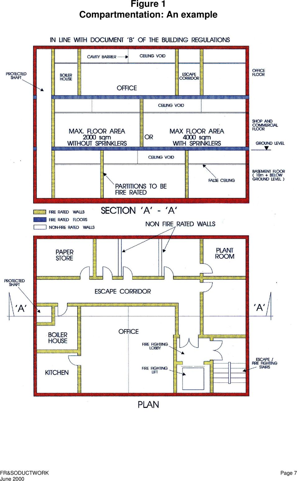
11 imposes an additional requirement on smoke outlet ductwork (i.e. the retention of at least 75% of its original cross sectional area during the test). 3.3 Dual Ventilation/Smoke Extraction Systems These systems serve as a conventional ventilation system under normal conditions, but are converted to a smoke extraction system in the event of fire, thus providing an economical dual system. 3.4 Pressurisation Systems Pressurisation is a method of restricting the penetration of smoke into certain critical areas of a building, by maintaining the air within them at pressures higher than those in adjacent areas. It applies particularly to protected stairways, lobbies and corridors, as smoke within these areas would inhibit escape, and also to firefighting shafts serving deep basements, because of the difficulties in clearing smoke from basements. A pressurisation system is a special form of mechanical ventilation system. However, as the air supply creating the pressurisation must be maintained for the duration of a fire, fire dampers cannot be used within the ductwork to prevent the spread of fire. Any duct or ductwork penetrating fire resisting barriers should therefore be fire resisting. BS 5588: Part 4 gives guidance on the use of pressurisation in buildings for the purpose of smoke control. 3.5 Car Park and Kitchen Extraction Systems Car parks and non-domestic kitchens are required to have separate and independent extraction systems, because of the polluted nature of the extracted air. As BS 5588: Part 9 recommends that fire dampers should not be installed in extraction ductwork serving car parks or kitchens, any duct or ductwork penetrating fire resisting barriers should be fire resisting. Kitchen extraction ductwork presents a particular hazard, in that combustible deposits such as grease are likely to accumulate on its internal surfaces. A fire in an adjacent compartment through which the ductwork passes could therefore initiate a fire within the ductwork which, in the absence of fire dampers, might prejudice the safety of the kitchen occupants. For this reason, BS 476: Part 24 imposes an additional requirement, (i.e. when tested as duct A against external fire) the internal surface of the ductwork within the furnace must meet the insulation criteria. It is also essential that this particular type of ductwork is provided with access for cleaning, at distances not exceeding 3m. FR&SODUCTWORK Page 6

12 Figure 1 Compartmentation: An example FR&SODUCTWORK Page 7
13 Figure 2 Types of extract ductwork from multi-cellular buildings FR&SODUCTWORK Page 8

14 Figure 3 Types of extract ductwork from multi-cellular buildings FR&SODUCTWORK Page 9

15 Figure 4 Types of extract ductwork from multi-cellular buildings FR&SODUCTWORK Page 10

16 Figure 5 Typical smoke outlet ductwork system FR&SODUCTWORK Page 11

17 Figure 6 Typical non-domestic kitchen extract ductwork FR&SODUCTWORK Page 12

18 Figure 7 Typical pressurisation ductwork system FR&SODUCTWORK Page 13

19 Figure 8 Typical basement car park extract FR&SODUCTWORK Page 14

20 4. REGULATIONS AND CODES 4.1 Introduction The documents listed in this section are most of the publications relevant to the performance requirements of ductwork in the event of a fire. For new buildings, buildings which are changing their use, and for extensions or alterations to existing buildings, one generally should refer to the guidance given in Approved Document B, (England and Wales), Technical Standards, Parts D and E (Scotland) or Technical Booklet E (Northern Ireland). For commercial and industrial buildings insurance may also be an important consideration. The Loss Prevention Council publish their recommendations in the LPC Design Guide for the Fire Protection of Buildings. 4.2 Statutory Instruments England and Wales - Building and Buildings - The Building Regulations 1991 (SI 1991 No. 2768) Scotland - Building and Buildings - The Building Standards (Scotland) Regulations 1990 (SI 1990 No (S187)) Northern Ireland - Building Regulations (Northern Ireland) 1994 (SRNI 1994 No. 243) 4.3 Documents Supporting the Statutory Instruments England and Wales - Approved Document B - Fire Safety Scotland - Technical Standards, Part D: Structural fire precautions and Part E: Means of escape from fire and facilities for fire-fighting Northern Ireland - Technical Booklet E - Fire Safety Some Publications referenced in Supporting Documents Fire Precautions Act Guide to fire precautions in existing places of work that require a fire certificate: Factories, offices, shops and railway premises Design principles for smoke ventilation in enclosed shopping centres. BR186,BRE,1990 (Revision of smoke control methods in enclosed shopping complexes of one or more storeys. A design summary. (BRE) 1979) Draft guide to fire precautions in existing residential care premises Home Office/Scottish Home and Health Dept Firecode HTM 81 - Fire precautions in new hospitals (NHS Estates) Firecode HTM 84 - Fire safety in residential care premises (Northern Ireland) Firecode HTM 85 - Fire precautions in existing hospitals (NHS Estates) Firecode HTM 86 - Fire risk assessment in hospitals (NHS Estates) Firecode HTM 88 - Guide to fire precautions in NHS housing in the community for mentally handicapped (or mentally ill) people (DHSS) Firecode - Nucleus fire precautions recommendations (D of H) Building Bulletin 7 - Fire and the design of educational buildings (DES) Guide to Safety at Sports Grounds Home Office/ Scottish Office FR&SODUCTWORK Page 15

21 London District Surveyors Association Fire Safety Guide No 1 - Fire Safety in Section 20 Buildings Fire Safety Guide No 2 - Fire Safety in Atrium Buildings Loss Prevention Council LPC Design Guide for the Fire Protection of Buildings 4.4 British Standards Institution (BSI) BS 476: Fire Tests on Building Materials and Structures Part 4: 1970 Non-combustibility test for materials 1984 Non-combustibility test for materials Part 6: 1981 Method of test for fire propagation for products 1989 Method of test for fire propagation for products Part 7: 1971 Surface spread of flame test for materials 1987 Method for classification of the surface spread of flame of products 1997 Method of test to determine the classification of the surface spread of flame of products Part 11: 1982 Method for assessing the heat emission from building materials 1988 Method for assessing the heat emission from building materials Part 20: 1987 Method for determination of the fire resistance of Elements of construction (general principles) Part 21: 1987 Methods for determination of the fire resistance of loadbearing elements of construction Part 22: 1987 Methods for determination of the fire resistance of non-loadbearing elements of construction Part 23: 1987 Methods for determination of the contribution of components to the fire resistance of a structure Part 24: 1987 Method for determination of the fire resistance of ventilation ducts (ISO 6944) BS 5588: Fire Precautions in the Design, Construction and Use of Buildings Part 1: 1990 Code of practice for residential buildings Part 2: 1985 Code of practice for shops (withdrawn, now superseded by BS 5588: Part 11) Part 3: 1983 Code of practice for office buildings (withdrawn, now superseded by BS 5588: Part 11) Part 4: 1978 Code of practice for smoke control in protected escape routes using pressurisation Part 5: 1991 Code of practice for fire-fighting stairs and lifts. Part 6: 1991 Code of practice for places of assembly. Part 8: 1988 Code of practice for means of escape for disabled people. Part 9: 1989 Code of practice for ventilation and air conditioning ductwork. Part 10: 1989 Code of practice for shopping complexes. Part Code of practice for shops, offices, industrial, storage and other similar buildings. FR&SODUCTWORK Page 16
22 BS 8313: 1989 Code of practice for accommodation of building services in ducts. BS ISO : Fire Resistance tests - Fire dampers for air distribution systems Part Test method. 4.5 International Organisation of Standardisation (ISO) ISO 834: 1975 Fire Resistance Tests - Part 1 General Requirements ISO 6944: Draft European Standards Fire Resistance Tests - Method for determination of the fire resistance of ventilation ducts. pren Fire resistance tests on service installations in buildings - Part 1: Fire resisting ducts pren Fire resistance tests on service installations in buildings - Part 2: Fire dampers pren Fire resistance tests on service installations in buildings - Part 3: Penetration Seals pren Fire resistance tests on service installations in buildings - Part 5: Service ducts and shafts pren Fire resistance tests on service installations in buildings - Part 8: Smoke extraction ducts pren Fire resistance tests on service installations in buildings - Part 9: Single compartment extract ducts 4.7 HVCA Documents DW/143 DW/144 DW/171 A practical guide to ductwork leakage testing Specification for sheet metal ductwork; low medium and high pressure velocity systems (supersedes DW/142) Specification for kitchen ventilation systems FR&SODUCTWORK Page 17
23 Figure 9 Regulations and Codes STATUTORY INSTRUMENTS BUILDING REGULATIONS INSURANCE REQUIREMENTS SUPPORTING DOCUMENTS BRITISH STANDARDS ADVISORY GUIDES Approved Document B (England and Wales) Technical Standards Parts D & E (Scotland) Technical Booklet E (Northern Ireland) LPC Design Guide for the Fire Protection of Buildings Codes of Practice Fire Tests BS 8313 BS 5588: Parts 1-6 Parts 8-11 BS ISO BS 476: Parts 4, 6, 7,11 Parts 20 to 24 LDSA Fire Safety Guide No 1 Fire Safety Guide No 2 Dept of Health HTM 81 HTM 84 HTM 85 HTM 86 HTM 88 FR&SODUCTWORK Page 18
24 5. STANDARD FIRE TESTS 5.1 Fire Resistance Test on Ducts Standard fire resistance tests on ventilation ducts are carried out in accordance with BS 476: Part 24 (ISO 6944). This standard specifies a method of test and criteria for the determination of the fire resistance of vertical and horizontal ventilation ducts under standardised fire conditions. The general purpose of the test is to measure the ability of a representative duct or duct assembly to resist the spread of fire from one compartment to another. The test is conducted without the involvement of fire dampers. It is applicable to vertical and horizontal ducts, with or without branches, taking into account joints, air supply and exhaust openings, as well as suspension devices and penetration seals. The performance of the duct assembly is measured in terms of its ability to withstand exposure to high temperatures by setting criteria by which the resistance to collapse - ensuring the duct is able to fulfil its intended function - (stability), the fire containment (integrity) and the thermal transmittance (insulation) functions can be judged. The standard temperature/time fire exposure specified in BS 476: Part 20 is representative of only one possible fire exposure condition at the fully developed fire stage. The method of test does not quantify the behaviour of a duct for a precise period of time in a real fire situation but can be used directly to show compliance with fire resistance requirements in regulations or other safety specifications, and enables comparisons to be made between constructions. The specimen which is subjected to the fire test must be designed and constructed to be representative of how it would be constructed on site. Two ducts are tested, one with fire outside only (duct A) and one with fire on the inside (duct B). Both ducts may be tested in either a horizontal or vertical orientation. See Figures 10 to 13. The minimum length of the specimen duct required by the test standard is 3.0m in the furnace and 2.5m outside the furnace for horizontal ducts and 2.0m in the furnace and 2.0m outside the furnace for vertical ducts. Horizontal duct A is fitted with a branch duct within the furnace. The recommended cross section of duct for test is 1.0m x 0.25m internally. A fan is connected to the end of horizontal duct A outside the furnace which induces an underpressure of 300Pa inside the duct. A fan is connected to the end of horizontal and vertical ducts B outside the furnace which induces air velocity of 3m/s within the ducts at ambient temperature drawn through an opening in the side wall of the duct within the furnace. The settings of the fan are not altered during the test. Every 30 minutes of the test the fans are switched off for five minutes to evaluate the integrity of the ducts in the fan off situation. The test specimen is subjected to fire on all four sides. The standard temperature/time fire exposure is followed and the pressure in the furnace at the height of the duct (or 100mm below the top of the furnace for vertical ducts) is controlled after the first five minutes of the test to be positive by 10 ± 2Pa compared to that of the laboratory. Thermocouples are applied to the non-fire face of the duct outside the furnace as required by the standard and extra thermocouples are included within the duct to gain additional data on the fire performance. These additional thermocouples enable assessments to be carried out on the duct system when used as a kitchen extract duct. Observations must also be made during the test regarding the retention of the cross-sectional area of the duct so that assessments can be made on the duct system when used as a smoke outlet duct. A smoke outlet duct should retain at least 75% of its cross-sectional area. The tested duct assembly is judged against three performance criteria. These are: FR&SODUCTWORK Page 19
25 Stability Stability failure shall be deemed to have occurred in duct A within the furnace and in ducts A and B outside the furnace when the duct collapses in such a manner that the duct no longer fulfils its intended function. Included in this is the ability of a smoke outlet duct to retain at least 75% of its cross-sectional area. Insulation Insulation failure shall be deemed to have occurred when the temperature rise above initial ambient temperature in the laboratory on the unexposed surface of the test specimen outside the furnace exceeds either i) 140 C as an average value; or ii) 180 C as a maximum value read by any surface thermocouple. For kitchen extract duct A, these temperature rise limits also apply to the inside surface of the duct within the furnace. Integrity The presence and formation in the test specimen of cracks, holes or other openings outside the furnace through which flames or hot gases can pass shall constitute integrity failure. Integrity failure shall also be deemed to have occurred when the cotton pad referred to in ISO 834 is ignited or when sustained flaming, of duration at least 10s, appears on the unexposed face of the test specimen outside the furnace. In order to interpret the presence and formation in the test specimen of cracks, holes or other openings outside the furnace through which flames or hot gases can pass, the following modes of failure under the integrity criterion of BS 476: Part 20 are adopted: Failure is deemed to occur: i) when a 6mm diameter gap gauge can penetrate through a gap and can be moved in the gap for a distance of at least 150mm; ii) when a 25mm diameter gap gauge can penetrate through a gap. Non-standard tests are carried out to the principles of BS 476: Part 24, but at reduced furnace temperatures, for applications such as smoke extraction systems where the maximum exhaust temperatures are specified and the ductwork does not penetrate fire separating elements. The results from similar tests can also be utilised for installations where a fire engineering analysis has been carried out on the building and the maximum temperature to which the duct would be exposed in a fire situation has been calculated. An example of such an installation is in an atrium of a multistorey building where the ducts are designed to extract smoke and hot gases in the event of a fire and to prevent flash-over occurring. BS 7346: Part 2 describes the classification and method of test for powered ventilators (not ductwork) designed to remove hot gases and smoke from buildings in the event of fire. The standard is primarily concerned with the evaluation of ventilator performance at elevated temperatures. FR&SODUCTWORK Page 20
26 5.2 Reaction to Fire Tests In order to restrict the use of materials in the construction of buildings which ignite easily, which have a high rate of heat release and/or which reduce the time to flashover, reaction to fire tests are carried out on component materials and linings of ducts. These are carried out to show compliance with reaction to fire requirements in regulations or other specifications. The tests which are used to demonstrate compliance are: Method of test to determine the classification of the surface spread of flame of products - BS 476: Part 7. This test measures the rate at which flame is able to spread over the surface of a lining material. The material or product is classified 1,2,3 or 4 with Class 1 being the highest classification (least flame spread). Method of test for fire propagation for products - BS 476: Part 6. This test measures the rate of heat release from a product or material. From this test, indices of performance are calculated. Index of performance (I) relates to the overall test performance, whereas sub-index (i 1 ) is derived from the first three minutes of test. The maximum acceptable fire propagation indices are specified in the various regulations. Method for assessing the heat emission from building materials - BS 476: Part 11, and Non-combustibility test for materials - BS 476: Part 4. These two tests are similar and are used to determine the heat emission from a product or material. Materials of limited combustibility are defined in the national Building Regulations by reference to the method of test specified in Part 11. Noncombustible materials are also defined in the national Building Regulations either as listed products or in terms of performance when tested to Part 4 or Part 11. Non-combustible materials may be used whenever there is a requirement for materials of limited combustibility. An additional product performance classification for lining materials defined in the national Building Regulations is Class 0. This is achieved if a material or the surface of a composite product is either: i) composed throughout of materials of limited combustibility, or ii) a Class 1 material which has a fire propagation index (I) of not more than 12 and sub index (i 1 ) of not more than 6. Class 0 is not a classification identified in any British Standard test. NOTE: The fire resistance tests and reaction to fire tests described above are the current UK national standards and reflect the requirements of the various UK national building regulations or other safety specifications. Work is proceeding within CEN to develop European Standards for fire resistance tests on ducts and reaction to fire tests. However, at the time of writing, these standards have only been published in draft form. FR&SODUCTWORK Page 21
27 Figure 10: Test arrangement for vertical ducts Typical test arrangement to BS 476: part 24: 1987 FR&SODUCTWORK Page 22
28 Figure 11: Test arrangement for horizontal ducts Typical test arrangement to BS 476: part 24: 1987 FR&SODUCTWORK Page 23
29 Figure 12: Location of thermocouples on vertical ducts outside the furnace (also see figure 10) Typical test arrangement to BS 476: part 24: 1987 FR&SODUCTWORK Page 24
30 Figure 13 Location of thermocouples on horizontal ducts outside the furnace Typical test arrangement to BS 476: part 24: 1987 FR&SODUCTWORK Page 25
31 6. FIELD OF APPLICATION FOR FIRE RESISTING DUCTS The field of application may be split into two distinct categories viz. Direct and extended fields of application. The field of direct application is derived from information obtained from tests carried out in accordance with BS 476: Part 24 at NAMAS accredited laboratories and means the test results achieved by a particular design may be directly applied to a number of variations (e.g. a reduction in duct size) without recourse to expert advice, providing the design remains substantially as tested. Extended application is primarily based on test evidence to BS 476: Part: 24 which may be supplemented by appropriate test evidence generated from other sources and considers variations not covered by direct application and variations which require modifications in the tested design (e.g. an increase in duct size) which necessitates the inclusion of a joint in the duct walls. 6.1 Field of Direct Application (Ducts Tested to BS 476: Part 24) Introduction The scope of the current BS test method does not consider the effect, detrimental or otherwise, that variations in the test construction may have on the achieved performance of the duct (i.e. the field of direct application is very limited). However, the appropriate European (CEN) standard will include a greater field of direct application which will allow certain modifications to tested configurations without the need to seek expert/specialist fire safety advice. At present the draft CEN test standard for ducts meant to be fire resisting has been prepared by the Technical Committee CEN/TC127 and is referenced pren 1366-Part 1. The draft test document includes guidelines with respect to the field of direct application and therefore presents acceptable changes to tested conditions and constructions. The principles of the draft test procedure are largely similar to those of the current BS test method. The field of application presented in the draft is therefore considered a reasonable basis. Critical Parameters The following text largely follows the principles of the draft document pr EN 1366: Part 1 suitably amended to conform to currently accepted good practice in the UK. Vertical and Horizontal Ducts A test result for horizontal ducts A and B is applicable to horizontal ducts only. A test result obtained for vertical ducts A and B is applicable to vertical ducts without a horizontal branch. However, if a test on a horizontal duct FR&SODUCTWORK Page 26
32 A with a branch is also undertaken the vertical ducts may include a horizontal branch. Sizes of Ducts A test result obtained for the standard sizes of ducts A and B is applicable to all internal dimensions up to the size tested and to sizes above that, subject to the following limits: Duct A Standard Size: Up to: Minus: Duct B Standard Size: Up to: Minus: Rectangular Width (mm) no limit no limit Rectangular Height (mm) no limit no limit Circular Diameter (mm) no limit no limit NOTE: Part 24 size requirement is full size but is usually of the order indicated above. For ducts tested with smaller sizes than the specified standard sizes, no extrapolation to larger sizes can be allowed. For ducts tested at sizes larger than the allowable upper limits for extrapolation, no further extrapolation to larger sizes is allowed. Pressure Difference The test results obtained for the standard underpressure of 300 Pa in duct A is applicable to an underpressure and an overpressure up to the same value. Height of Vertical Ducts Ducts supported at each storey The test results are applicable to any number of storeys provided: i) the distance between supporting constructions does not exceed 3m (unless intermediate supports are provided) or 1.5 times the height tested whichever is the lesser. ii) limitations on buckling are satisfied Self Loadbearing Ducts Test results, obtained from ducts with additional loads, are applicable to ducts with an overall height corresponding to the load applied in the fire test. Limitations on buckling shall also be satisfied. Limitations on Buckling In order to prevent self damage from the buckling of vertical ducts, the test results are only applicable to situations where the ratio between the length of the duct exposed in the compartment and the smallest lateral dimension across the outside face of the duct (or outer diameter) does not exceed 8, unless additional supports are provided. FR&SODUCTWORK Page 27
33 In cases where additional supports have to be provided, the ratio of the distance between the additional supports, or the distance between the additional supports and the supporting construction, and the smallest lateral dimension across the outside face of the duct, shall not exceed 8. Support systems - Horizontal Ducts Horizontal ducts are typically supported along their length by a system of frames and fire resisting fixings to the building structure, which generally consist of vertical hangers connected to a horizontal member, or members. The vertical hangers are fixed to the building structure above the duct. Unprotected hangers made of steel may be sized such that the calculated stresses do not exceed the values given as follows: Allowable Tensile Stress Tensile stress in all vertically oriented components Up to 60 minutes Over 60 minutes up to 120 minutes Over 120 minutes up to 240 minutes 15 N/mm 2 10 N/mm 2 6 N/mm 2 Note 1: The elongation in mm of the hangers of the test ducts can be calculated on the basis of temperature increases and stress levels. For unprotected supporting systems, the temperature used will be the maximum furnace temperature. For protected steel hangers, the maximum recorded hanger temperature, if available, shall be used. The value represents the elongation limit for hangers with a greater length than in the test. Note 2: Stress is calculated from supported load only. An example for the calculation of tensile stress in vertical hanger members: W = weight of duct assembly per unit length - kg/m W b = weight of bearer per unit length - kg/m W r = weight of drop rod per unit length - kg/m L h = distance between hanger supports - m L b = length of bearer - m h = height of drop rod - m A = cross section area of drop rod * - mm 2 Weight of duct on each hanger support = (W x L h ) kg Weight of hanger support = (W b x L b + 2W r x h) kg Therefore tensile strength stress in drop rod (σ) = (W x L + WbxLb 2W 2A h + r x h) x 9.81 N/mm 2 * If the drop rod is a threaded rod then A is based on the root diameter. Note 3: The maximum tested stress may be used if greater than above. Note 4: The largest distance between frames of the support systems used in the test construction must not be exceeded in practice. Note 5: If frames of the support system have been positioned at all joints within the furnace, then these must be located at all joints in practice. FR&SODUCTWORK Page 28
34 Note 6: In cases where the lateral dimension between the outer vertical surface of the duct and the centre line of the vertical hanger rod is less than 50mm, the test result will apply up to 50mm. The lateral dimension must not exceed 50mm unless demonstrated by test. The horizontal loadbearing component of the support system shall be sized so that the bending stress does not exceed that applied to the equivalent member in the test. Compensators If compensators providing for expansion have been incorporated in the test, in practice the distance between each compensator must not be more than 10m. Where the duct passes through a wall, the compensator must be located not more than 5m from the wall. Supporting Construction For the purpose of this publication the supporting construction is the wall or floor through which the duct passed under test. In practice it may be referred to as a compartment floor or wall or separating element. Consequently a test result obtained for a fire resisting duct passing through a wall or floor made of masonry, concrete or a partition (without any cavity) is applicable to the same type of construction providing its thickness and density is equal to or greater than that used for the test. Ducts Provided a duct is selected for test representing a certain leakage value, the test results will apply to those ducts having lower leakage values. (See HVCA publications DW/143 and DW/144.) Test results on a steel duct that has been stiffened shall only apply to ducts that are also stiffened in a similar manner. Penetration Seal It is important in order to maintain the performance of the duct that the position where it passes through the supporting construction is effectively sealed. The test method considers this seal to be an integral part of the duct construction. Therefore, for the field of direct application, it must be constructed of the same material and be installed using the same method as tested. The gap dimension between the inside edge of the supporting construction and the perimeter of the duct and hence the seal thickness must also remain as tested. 6.2 Extended Application Specialist technical advice should be sought from a competent organisation if desired variations in the tested construction are not included within the field of direct application. Such variations may include the following: i) Increase in size of duct beyond direct application; ii) iii) iv) Ducts with 1,2 or 3 sides; Variation in supporting method; Change in duct construction (e.g. alternative materials); v) Change in duct orientation (e.g. from horizontal to vertical); FR&SODUCTWORK Page 29
35 vi) vii) viii) ix) Change in duct use (e.g. ventilation to smoke extract); Change in duct shape; Variation in jointing method; Variation in penetration sealing system. The above list is not exhaustive and acceptable variations are subject to test performance and duct design. It is prudent to consider the intended range of ducts to be offered prior to testing to ensure a large number of tests are avoided. For the purpose of assessments for the extended field of application suitably qualified fire safety engineers and laboratories accredited by NAMAS for conducting the relevant tests might be expected to have the necessary expertise. 7. NOTES ON PENETRATION SEALS, SUPPORT SYSTEMS AND ANCILLARY ITEMS 7.1 Penetration Seals Where ductwork passes through a compartment wall or floor it must be ensured that the fire separation of the wall or floor is maintained. This is usually achieved in one of two ways: i) For fire rated ductwork a penetration seal is fitted between the duct and the wall or floor. The penetration seal and the ductwork are considered as one integral system and for the field of direct application must be the same as that tested or assessed in accordance with BS 476: Part 24. ii) For non-fire rated ductwork a fire damper must be fitted in the plane of the wall or floor. The damper and associated penetration seal must be installed to a procedure substantiated by test or assessment. Note that the damper must be mounted in the wall or floor and must be supported/restrained independently of the ductwork. Where fire rated ductwork adjoins a damper fitted in a wall or floor the penetration seal to the wall or floor must be installed as (ii) above. The fire resistance test for ducts (BS 476: Part 24) is designed to evaluate the fire performance of the duct penetration seal system through a wall or floor construction (the fire separating element), as well as the fire performance of the duct system itself. The purpose of the penetration seal system is to seal the gap between the duct walls and the surrounding wall or floor. In a fire situation, an integrity failure of the penetration seal system is often caused by the movement or distortion of the duct. Therefore it is not possible to separate the fire performance of the penetration seal from the construction of the duct. A successful test on a penetration seal fitted around one type of duct construction does not mean that the penetration seal is suitable for use with a different type of duct construction. Similar comments apply for duct sizes other than that tested. Usually the penetration seal will be suitable for duct sizes smaller than that tested, but the construction of the duct may have to be modified or the duct locally strengthened at the penetration, for duct sizes larger than that tested. Most of the fire tests on duct penetration seal systems have been carried out through concrete floors or masonry/concrete walls. If the fire separating element is of a different type of construction from that tested, for example a timber floor or a fire rated partition system, then an indicative fire test and an assessment should be carried out to FR&SODUCTWORK Page 30
36 ensure that the duct penetration seal system and/or any damper restraint system is compatible with the different fire separating element for the required fire rating. The fire tests on ducts are carried out on specimens in the horizontal orientation and in the vertical orientation. The fire performance of the penetration seal system must be demonstrated for the orientation in which the duct is being used, or have been assessed as being suitable. If the penetration seal system fails to satisfy the test criteria during the test then the duct or damper system is also deemed to have failed. 7.2 Support Systems The support systems used for fire rated ductwork must be capable of bearing the load of the ductwork under fire conditions. The support system consists of the hangers and bearers, the fixings and brackets. Attention must be given to the spacing of the supports and the size of the support components in accordance with the manufacturer s test data and recommendations. The maximum allowable span of the duct between supports must not be exceeded, the maximum distance of the hangers from the side of the duct must not be exceeded and the maximum allowable stress within the components of the supports must not be exceeded for the required fire rating. Stresses within the support components can be reduced by increasing the size of the components, or reducing the spacing of the supports, or applying fire protection to the support systems. If supports were positioned at all duct joints within the furnace in the fire test then the supports must be located at all duct joints in practice. The element of building construction to which the support systems are attached must have a fire rating of at least that specified for the duct and be able to support the weight of the duct under fire conditions. 7.3 Ancillary Items/In-Line Equipment A fire rated duct will often adjoin a component or structure which does not form part of the tested ductwork system, and could have in-line equipment and control devices such as balancing dampers, filters, attenuators, fans, etc. The performance characteristics of the fire-rated duct must be continued through these ancillary items of equipment to ensure the fire resistance of the system is maintained. Fire Dampers It is not appropriate for fire rated ductwork to be required to rectify the incorrect installation or positioning of dampers (e.g. in situations where a damper tested only for installation in the plane of a wall or floor has been installed remote from a wall or floor). 7.4 Interface between Fire Rated Ductwork and Elements of Building Construction Responsibility for the satisfactory performance of each element of building construction (e.g. walls, floors, cavity barriers, etc.) lies with the installer of each particular element. The change over of responsibility occurs at the interface between the fire rated ductwork and the elements. It is imperative that the interface detail does not compromise the fire performance of either the element of building construction or the fire rated duct. The building designer, mechanical services designer and the installer all have a responsibility to pay due care to this detail. FR&SODUCTWORK Page 31
37 8. LIMITATIONS This list sets out the principal limitations in the scope of the guidance given in this publication and is not intended to be exhaustive. The term Fire Rated Ductwork is deemed to refer to a system as tested or assessed in accordance with BS 476 : Part 24. As the vast majority of tests on steel ducts are conducted with rigid ducts it is not appropriate to extrapolate this data for flexible steel ducts. Therefore, unless the flexible steel duct system has been tested in accordance with BS 476 : Part 24, this guidance note cannot be assumed to apply. Service ducts are not included within this guidance note. Fire rated ductwork systems shall be deemed to include all the components as tested or assessed, including supporting systems and penetration seals. Reference is made to the Field of Application section within this guidance note. The element of building construction to which the support systems are attached must have a fire rating of at least that specified for the duct and be able to support the weight of the duct under fire conditions. Fire resistance of a fire rated ductwork system shall be expressed as the three time period components - stability, integrity and insulation. Where only a single time period is expressed it shall be deemed to apply to all three components, unless clearly defined otherwise. (e.g. 90 minutes, stability & integrity only). It is essential when choosing a fire rated duct system that it is fit for the purpose to which it is being applied. Considerations other than the successful completion of a BS 476 : Part 24 fire test on a sample section of ductwork may need to be given when assessing the suitability of a fire rated duct for a particular application. Reference may be made to the footnotes to the Table in Explanatory Note A8 within the Annex to BS 476 : Part 24. During any defined non-fire operating conditions, fire rated ductwork must be capable of both performing and being tested to the ductwork classification and the air leakage limits of the designated ductwork specification (e.g. DW/144 (142)). In general, the air flow characteristics of ductwork and its associated components such as bends, branches and changes of section must all be in accordance with both DW/144 (142) and CIBSE Technical Memoranda TM8, Design Notes for Ductwork. In the case of an existing metal duct, where application of a fire insulation cladding material to provide fire resistance is considered, it is imperative that the construction standard of the metal duct is checked for conformity with the appropriate fire test report. Similarly, the construction of a newly erected metal duct should be the subject of like scrutiny. Metal gauge, spacing & size of flanges and stiffeners, bolting centres, use of steel / aluminum rivets, sealants, spacing of hanger supports and fixing method to the soffit should all be checked for compliance with the fire tested construction. It is not sufficient to rely on a DW/144 (142) construction classification for fitness for purpose in this regard. For the purposes of independent assessment, suitably qualified fire safety engineers and laboratories accredited by NAMAS for conducting the relevant test might be expected to have the necessary expertise. FR&SODUCTWORK Page 32
38 It is recommended that the installed fire rated duct system be verified by the use of a quality system, based upon the ISO 9000 Series. This will enable the supplier/installer to provide documentary evidence of the conformity of the installed system and its components. Verification will require to include research, checking or test of existing ductwork installations which are being modified and / or overclad to provide a fire rated system. Light gauge specifications such as DW/144 (142) recognise many machine forming techniques for ancillary items such as air turning vanes and the increased gauges associated with fire rated ductwork systems may not only preclude the use of such techniques but may also, out of necessity, introduce a geometric change that may require the approval of the HVAC designer in terms of a component's air flow characteristics. A fire rated duct tested to BS 476 : Part 24 (Ventilation duct test) which meets criteria of stability, integrity and insulation may not be suitable for kitchen extract application or smoke extract application unless proven by additional test criteria, as outlined in the Explanatory Notes Annex to the Standard (A.1(c) & A.8). For the field of direct application penetration seals to be the same as tested in the BS 476 : Part 24 test. The adequacy of damper installations to which a fire rated duct may be connected is assumed by this guidance note. However it is incumbent upon the designers and providers of such damper installations to verify that they have been appropriately tested adopting the procedures and criteria of BS 476: Part 20. This guidance note does not address the complex and detailed issue of fire and/or smoke dampers or any other fire resisting components or elements of structure with which the fire rated ductwork system interfaces, save for their assumed levels of adequacy. Responsibility is therefore deemed to end with the interface connection. Special care must be taken with in-line items of equipment such as fans, volume control dampers, attenuators etc. Where such items are within a fire rated ductwork run, the item of equipment must maintain the full fire performance of the duct into which it is fitted or it must be installed within its own fire rated enclosure (same performance as the duct). Access provisions to the ductwork for cleaning and maintenance should also maintain the fire performance of the duct to which they are fitted. This publication does not consider the effect of expansion of ductwork in fire conditions. Therefore, it is recommended that the specifier takes this phenomenon into consideration when designing the ductwork route. If it is considered that expansion of the ductwork could cause excessive forces on the associated wall or floor penetration seals, (which, could result in their failure under fire conditions), the ductwork route should either be reconsidered (to lessen the effect of expansion on the penetration seals), or fire resisting expansion devices/compensators should be included within the ductwork. 9. STANDARD SPECIFICATION In order to ensure fire rated ductwork is correctly specified prior to the commencement of work, several factors should be carefully considered and defined. FR&SODUCTWORK Page 33
39 The Specification should therefore: (1) Define Type: i.e.; Smoke / Ventilation / Kitchen / Pressurisation (2) Define if System is Duct Type A (fire outside) or Duct B (fire inside) or requirement for both Fire Inside and Fire Outside (3) State Fire Rating to BS 476: Part 24 in minutes for: i) Stability ii) Integrity iii) Insulation (4) Define Static Pressure Limits i) Low pressure/velocity Class A up to 500 Pa positive or 500 Pa negative ii) Medium pressure/velocity Class B up to 1000 Pa positive or 750 Pa negative iii) High pressure/velocity Class C up to 2000 Pa positive or 750 Pa negative Note: Classifications are to DW/144 (142) requirements. (5) The Fire Duct manufacturer should define the friction resistant coefficients of all bends and tapers, etc. which are to be used if they differ from those for galvanised sheet steel. (6) It is recommended that the manufacturer/installer is working to a Quality Assurance System based upon the ISO 9000 series. With reference to the above factors, the standard Specification should read: The (1) Ductwork should be constructed in accordance with the ASFP Guide to Fire Rated and Smoke Extract Ductwork to provide (3)i) minutes stability, (3)ii) minutes integrity, and (3)iii) minutes insulation when tested to the requirements of BS 476: Part 24 by a NAMAS approved laboratory. The ductwork should be capable of providing Type (2) fire containment and, under normal non-fire operating conditions, should conform to the (4) pressure classification of the current HVCA DW/144 (142) Specification for Sheet Metal Ductwork. FR&SODUCTWORK Page 34
40 10. STANDARD METHOD OF MEASUREMENT OF BUILDING WORKS The measurement of fire resisting ductwork should follow the guidelines of Table Y30/Y31 on pages 156 and 157 of SMM7 (Standard Method of Measurement of Building Works Seventh Edition). It is essential that any bill of quantities description for fire resisting ductwork includes ALL of the following: System type (eg: kitchen extract) Duct size Duct shape Fire resisting requirement (eg: 60 minutes stability, 60 minutes integrity and 60 minutes insulation when tested in accordance with BS 476: Part 24) Fire resisting ductwork must be measured as a complete item in linear metres with ancillaries and fittings described and measured separately. 11. DATA SHEETS The ASFP member companies listed on the following pages are able to supply, or supply and install, a full range of fire rated and smoke outlet ductwork systems and/or materials. It should be noted, however, that it is the responsibility of the specifier/end user to ensure the system(s) or material(s) will satisfy the requirements of relevant building legislation. It is therefore important that any system(s) or material(s) offered is supported by a relevant fire test report(s) or assessment(s) from a UKAS (NAMAS) approved fire test laboratory. The second edition of this publication will include data sheets, which will provide full details of fire tested systems that have been tested and assessed by UKAS approved fire test laboratories and checked by the ASFP Technical Review Panel. FR&SODUCTWORK Page 35
41 SUPPLIERS AND INSTALLERS CAFCO INTERNATIONAL Bluebell Close, Clover Nook Industrial Park, Alfreton, Derbyshire DE55 4RA t: f: FIRE PROTECTION LTD Millars 3, Southmill Road, Bishops Stortford, Herts CM23 3DH t: f: PROMAT UK LTD The Sterling Centre, Eastern Road, Bracknell, Berks RG12 2TD t: f: ROCKWOOL LTD Pencoed, Bridgend, Mid Glamorgan CF35 6NY t: f: SENIOR HARGREAVES Lord Street, Bury, Lancashire BL9 0RG t: f: THERMAL CERAMICS Tebay Road, Bromborough, Wirral, Cheshire CH62 3PH t: f: FR&SODUCTWORK Page 36
The risk assessment of fire damper installations
 The risk assessment of fire damper installations June 2010 Paul White OVERVIEW OVERVIEW The purpose of this presentation is to highlight that fire dampers form a key part of the passive fire protection
- 5 - Table1. Maximum Compartment Volumes
 - 5 - Part II - SPECIFIC REQUIREMENTS 5. Compartmentation 5.1 Every building should be divided into compartments by walls and floors to inhibit the spread of fire. 5.2 Compartment walls, compartment floors,
Services Enclosures and Protected Shafts - Maintaining Compartmentation
 Introduction When a fire resisting element is used to provide fire compartmentation, every opening that allows services to pass through the element must be adequately protected by sealing, or fire stopping
INTERNATIONAL ASSOCIATION OF CLASSIFICATION SOCIETIES. Interpretations of the FTP
 INTERNATIONAL ASSOCIATION OF CLASSIFICATION SOCIETIES Interpretations of the FTP CONTENTS FTP1 Adhesives used in A or B class divisions (FTP Code 3.1, Res A.754 para. 3.2.3) June 2000 FTP2 Pipe and duct
Fire safety in timber buildings
 Fire safety in timber buildings Introduction Fire spread in buildings is a risk to life safety for which the Building Regulations (for England and Wales 1,2, Scotland 3 and Northern Ireland 4 ) aims to
Excerpts from the Canadian National Building Code (NBC)
") Excerpts from the Canadian National Building Code (NBC) Reproduced here with Permission of the Copyright Owner, the National Research Council of Canada, Institute for Research in Construction. For more
Excerpts from the Canadian National Building Code (NBC) Reproduced here with Permission of the Copyright Owner, the National Research Council of Canada, Institute for Research in Construction. For more
Decree of the Ministry of the Environment on fire safety of ventilation systems
 THE NATIONAL BUILDING CODE OF FINLAND MINISTRY OF THE ENVIRONMENT Housing and Building Department Decree of the Ministry of the Environment on fire safety of ventilation systems Adopted in Helsinki, 18
Fire Stopping and Penetration Seals for the Construction Industry SECOND EDITION
 Fire Stopping and Penetration Seals for the Construction Industry SECOND EDITION Fire Test Study Group 1 INTRODUCTION The (ASFP) was formed in 1976. The objectives of the Association are to encourage,
Australian/New Zealand Standard
 Australian/New Zealand Standard The use of ventilation and air conditioning in buildings - Part 1: Fire and smoke control in buildings UPDATED AS/NZS 1668.1:2015 What is the scope of this Standard? The
UPP Residential Services Fire Risk Assessment
 UPP Residential Services Fire Risk Assessment TS11151-R02-DRAFT1 15 August 2011 for: Keynes College University Road Canterbury Kent Recommended latest review date 14 August 2011 Executive summary This
Fire 2This Technical Bulletin has been commissioned by the UK SIP Association in
 REV 1-12.12.11/TB002 Technical Bulletin Fire 2This Technical Bulletin has been commissioned by the UK SIP Association in conjunction with TRADA Technology and is intended to provide the reader with introductory
Terms and Definitions In Canada
 Terms and Definitions In Canada Most of the following terms and definitions are taken directly from the National Building Code and referenced Test Methods. Learning these terms will provide an important
Introduction. CE marked construction products
 Introduction This Technical Booklet has been prepared by the Department of Finance and Personnel and provides for certain methods and standards of building which, if followed, will satisfy the requirements
Ontario Fire Code SECTION 5.13 DIP TANKS. Illustrated Commentary. Office of the Ontario Fire Marshal
 Ontario Fire Code SECTION 5.13 DIP TANKS Illustrated Commentary Office of the Ontario Fire Marshal Dip Tanks Illustrated Commentary 1 5.13.1. Location 5.13.1.1. Dip tank operations involving flammable
Fire Protection Of Ventilation Systems DAMPERS & AIR TRANSFER GRILLES A PRESENTATION BY PHILLIP HORTON OF FIRE ENGINEERING SOLUTIONS
 Fire Protection Of Ventilation Systems DAMPERS & AIR TRANSFER GRILLES A PRESENTATION BY PHILLIP HORTON OF FIRE ENGINEERING SOLUTIONS THE AIM OF THE WORKSHOP: Provide assistance in the selection, installation
Certification of construction products - Fire dampers. Certification Rules 032
 Certification of construction products - Fire dampers Certification Rules 032 1 Contents Contents 1 0 Preface 1 1 Scope and intended application 2 2 Technical requirements 2 2.1 Properties 2 2.1.1 Protection
Using Sprinkler Systems in Buildings and Structures Compliance with current fire safety guidance
 Technical Guidance Note No 2 Issue No 1: October 2011 ISBN 0-9552628-8-7 Using Sprinkler Systems in Buildings and Structures Compliance with current fire safety guidance In this Technical Guidance Note
FIRE-RESISTANT GLAZING Mr Leslie O May Sales Consultant Wright Style Limited England
 FIRE-RESISTANT GLAZING Mr Leslie O May Sales Consultant Wright Style Limited England Fire is a life-threatening and destructive force, which if unchecked, can spread rapidly through a building. Every year,
Passive Fire Protection Guidance for the Fire Risk Assessor. Niall Rowan Technical Officer Association for Specialist Fire Protection
 Passive Fire Protection Guidance for the Fire Risk Assessor Niall Rowan Technical Officer Association for Specialist Fire Protection ASFP has just completed a guide on what to look for when undertaking
Guidance on loft conversions in two-storey houses
 Guidance on loft conversions in two-storey houses Technical guidance for building control surveyors, designers and installers 01 Guidance on loft conversions in two-storey houses Technical guidance for
CERTIFICATE NAME OF PRODUCT MANUFACTURER PRODUCT DESCRIPTION CERTIFICATION PROCEDURE. No VTT C-6044-10 Date of issue 11.10.2010, Updated July 1, 2011
 CERTIFICATE NAME OF PRODUCT No VTT C-6044-10 Date of issue 11.10.2010, Updated July 1, 2011 H-CONTROL REFLEX+ reflective insulating vapour control layer for roof and wall applications MANUFACTURER ACTIS
Fire-resistant barriers: background on requirements and determination method. Reading guide for test reports.
 Fire-resistant barriers: background on requirements and determination method. Reading guide for test reports. Report number C 1395-1E-RA-003 d.d. May 14, 2014 Fire-resistant barriers: background on requirements
Tremco Fire Protection Systems Group Technical Bulletin
 Compartmentalization products and design play a key role in protecting lives and property from fire. Understanding the tools and techniques available for firestopping is of utmost importance to designers,
Loss Prevention Standard
 Loss Prevention Standard LPS 1581: Issue 2.1 Requirements and tests for LPCB approval of nonload This Loss Prevention Standard is the property of BRE Global Ltd. and is made publicly available for information
GENERAL + MEANS OF ESCAPE (Part One) By Mdm Eng Yew Hoon (SIA)
 By Mdm Eng Yew Hoon (SIA)") GENERAL + MEANS OF ESCAPE (Part One) By Mdm Eng Yew Hoon (SIA) Chapter 1 : Definitions clause 1.2.10 : circulation space OLD CLAUSE A space mainly used as means of access between a room or protected shaft
GENERAL + MEANS OF ESCAPE (Part One) By Mdm Eng Yew Hoon (SIA) Chapter 1 : Definitions clause 1.2.10 : circulation space OLD CLAUSE A space mainly used as means of access between a room or protected shaft
CERTIFICATE OF APPROVAL No CF 5055 ARABIAN VERMICULITE INDUSTRIES
 CERTIFICATE OF APPROVAL No CF 5055 This is to certify that, in accordance with TS00 General Requirements for Certification of Fire Protection Products The undermentioned products of 1 st Industrial Area,
1-085 Fire safety performance of materials
 Transport for London London Underground Category 1 Standard 1-085 Fire safety performance of materials! Please read the Written Notices attached to this standard Issue: A3 MAYOR OF LONDON Contents 1 Purpose
Code of Practice for fire resisting metal doorsets
 COP 1005 Code of Practice for fire resisting metal doorsets Scope The aim of this document is to provide guidance on the best practice for, and a better understanding of, hinged or pivoted fire resisting
LPCB Red Book Listed Products and Passive Fire Protection Installer Schemes Answering the needs of the market
 LPCB Red Book Listed Products and Passive Fire Protection Installer Schemes Answering the needs of the market Ian Stewart Passive installer scheme manager September 2011 Introduction to BRE Global Research,
Loss Prevention Standard
 Loss Prevention Standard : ISSUE 3.0 Requirements for the LPCB Approval and Listing of Companies Undertaking the Maintenance and Repair of Doorsets, Shutters, and Active Smoke/Fire Barriers This standard
Isover HVAC Application Handbook Installing fire protection insulation to metal ductwork
 Isover HVAC Application Handbook Installing fire protection insulation to metal ductwork HVAC - Fire protection of metal ductwork Fire protection Thermal insulation Isover ULTIMATE TM Protect - Fire protection
FIRE LOSS STATISTICAL CONSIDERATIONS IN RELATING FAILURE AND BUILDING DAMAGE TO THE BUILDING CODE OBJECTIVES
 FIRE LOSS STATISTICAL CONSIDERATIONS IN RELATING FAILURE AND BUILDING DAMAGE TO THE BUILDING CODE OBJECTIVES P.L. Senez*, K.D. Calder, Hsing H (Isabella) Li Sereca Fire Consulting Ltd., Canada INTRODUCTION
English Version. Fire safety storage cabinets - Part 2: Safety cabinets for pressurised gas cylinders
 EUROPEAN STANDARD NORME EUROPÉENNE EUROPÄISCHE NORM EN 14470-2 August 2006 ICS 13.220.40; 71.040.10 English Version Fire safety storage cabinets - Part 2: Safety cabinets for pressurised gas cylinders
Report Number BTC 17755F
 Leics. LE NP Tel () 4 Fax () 4 Email [email protected] Report Number BTC 77F A FIRE RESISTANCE TEST ON A LOADBEARING TIMBER JOIST FLOOR INCORPORATING 4mm x 7mm x 47mm SOLID JOISTS PROTECTED BY
AVAILABLE TO DOWNLOAD ON THE APOLLO APP. Fire Alarm Systems Design. a guide to BS5839
 AVAILABLE TO DOWNLOAD ON THE APOLLO APP a guide to Fire Alarm Systems Design BS5839 Part1:2013 The Regulatory Reform (Fire Safety) Order (FSO) became law on 1 October 2006 Legally you must comply! What
SPECIFIC GUIDANCE FOR A HOUSE IN MULTIPLE OCCUPATION (HMO) CONVERTED ENTIRELY INTO SELF CONTAINED FLATS
 CONVERTED ENTIRELY INTO SELF CONTAINED FLATS") Document F SPECIFIC GUIDANCE FOR A HOUSE IN MULTIPLE OCCUPATION (HMO) CONVERTED ENTIRELY INTO SELF CONTAINED FLATS This document is intended as a specific guide for persons who own, manage or control Houses
Document F SPECIFIC GUIDANCE FOR A HOUSE IN MULTIPLE OCCUPATION (HMO) CONVERTED ENTIRELY INTO SELF CONTAINED FLATS This document is intended as a specific guide for persons who own, manage or control Houses
We hope these Frequently Asked Questions will be of use both to municipal officials and fire inspectors.
 September 14, 2012 Dear AMM Member: Please see the attached Fire Code Frequently Asked Questions. This document was compiled by the Office of the Fire Commissioner at the AMM s request to help clarify
Loss Prevention Standard
 Loss Prevention Standard LPS 1181: PART 1: ISSUE 1.1 Series of Fire Growth Tests for LPCB Approval and Listing of Construction Product Systems Part One: Requirements and Tests for Built-up Cladding and
GENERAL FIRE SAFETY TERMS & DEFINITIONS
 UCL Fire Technical Note - TN006 Fire Safety Technical Guide GENERAL FIRE SAFETY TERMS & DEFINITIONS Reference: BS4422-2005 Fire Safety Vocabulary - for further information and definitions BS EN ISO 13943-2000:
Fire Preventive and Fireproof Performance Test and Evaluation Procedure Manual
 BR BO-01-02 Effective from June 1, 2000 Revision: March 26, 2002 Fire Preventive and Fireproof Performance Test and Evaluation Procedure Manual (Unofficial Manual) Technical Appraisal Department, Building
Fire Safety Requirements for Child Care Centre
 Fire Safety Requirements for Child Care Centre A. Restrictions on Location Child care centre shall not be located : - (a) (b) in any premises designed for residential use; in any industrial building, warehouses,
ON MOST schemes, the architectural design of. Flexible strategy. Case study. The Forum
 Flexible strategy ON MOST schemes, the architectural design of a building is influenced by fire engineering strategy. This could be in the form of visual, physical elements such as fire doors, fire curtains,
Colorcoat Technical Paper Fire performance of pre-finished steel cladding systems
 CI/SfB (4-) Nh2 (A3j) May 2013 CI/SfB (4-) Nh2 (A3j) May 2013 Colorcoat Technical Paper Fire performance of pre-finished steel cladding systems MINIMISING FIRE RISK Tata Steel have a long history of product
FIRE-RESISTANCE-RATED CONSTRUCTION
 CHAPTER 7 FIRE-RESISTANCE-RATED CONSTRUCTION SECTION 70 GENERAL 70. Scope. The provisions of this chapter shall govern the materials and assemblies used for structural fire resistance and fire-resistance-rated
Part 3 Ancillary technologies. Chapter 3.2. Mechanical ventilation with heat recovery
 Part 3 Ancillary technologies Chapter CONTENTS SCOPE Clause Page DESIGN Design standards D1 1 Statutory requirements D2 1 System design D3 1 Building integration D4 2 Noise D5 2 Access and controls D6
A Guide to Best Practice in the Specification and Use of Fire-Resistant Glazed Systems
 Cl/SfB Ro Summer 2011 A Guide to Best Practice in the Specification and Use of Fire-Resistant Glazed Systems Issue 3 Introduction Introduction Table of Contents Introduction by Chairman 7 Terms used in
Building Control Guidance Note
 Issued 01/10/10 Rev Page 1 A new updated version of Approved Document B comes into force from the 6 th April 2007. This revised guidance is split into two separate documents:- Volume 1 Dwelling Houses
Dubai Municipality Standard DMS 1: Part 5: 2004
 Specification for precast concrete blocks Part 5: Normal-weight concrete-polystyrene sandwich masonry blocks Issue Date Revision Revision Description Prepared by Approved by Authorized by 19/12/2004 Issue
4 Installation Requirements
 4 Installation Requirements 9 4.1 Code Reference The authority having jurisdiction should be referenced to determine what law, ordinance or code shall apply in the use of flexible duct. Ducts conforming
Certification: Building Plans Examiner. Exam ID: B3
 Certification: Building Plans Examiner Exam ID: B3 Scope: A Building Plans Examiner will be responsible for reviewing submitted plans to determine if they meet the requirements of the various Building
ASTACEA4 Inspect complex/central air conditioning systems
 Overview This Unit covers the competences required to inspect complex/central air conditioning systems as defined by the CIBSE TM 44 Figure 1.1: Summary of system types and their component parts. The air
The FIRE BOOK. Passive fire protection solutions
 The FIRE BOOK Passive fire protection solutions The importance of providing effective fire protection to buildings cannot be over-emphasised. The consequences of a fire occurring in a building, without
Fire safety in buildings and implementation of European fire test standards
 Fire safety in buildings and implementation of European fire test standards Dr Debbie Smith OBE Chair of CEN TC127 Fire Safety BRE Global Ltd, UK 18 th June 2014 Part of the BRE Trust Construction Products
European Organisation for Technical Approvals
 Warrington Certification Limited, Holmesfield Road, Warrington, WA1 2DS Tel. +44 (0) 1925-646777 Fax +44 (0) 1925-646667 Member of EOTA Authorised and notified according to Article 10 of the Council Directive
NORSOK STANDARD H-001 Rev. 4, Nov. 2001. Heating, ventilation and air-conditioning
 NORSOK STANDARD H-001 Rev. 4, Nov. 2001 Heating, ventilation and air-conditioning This NORSOK standard is developed by NTS with broad industry participation. Please note that whilst every effort has been
FIRE-RESISTANCE-RATED CONSTRUCTION
 CHAPTER 7 FIRE-RESISTANCE-RATED CONSTRUCTION SECTION 70 GENERAL 70. Scope. The provisions of this chapter shall govern the materials and assemblies used for structural fire resistance and fire-resistance-rated
BUILDING CONTROL GUIDANCE SHEET REPLACEMENT WINDOWS AND DOORS Last updated 16/11/2010
 Building Control Charnwood Borough Council Southfield Road Loughborough LE11 2TN BUILDING CONTROL GUIDANCE SHEET REPLACEMENT WINDOWS AND DOORS Last updated 16/11/2010 Page 1 of 6 PURPOSE: This Guidance
Building Code Clarifications - 7. Fire Resistance
 Building Code Clarifications - 7. Fire Resistance 7.1 (15-12-030) Use of combustibles in Type III construction roof assemblies Code Section (15-12-030) Use of Combustibles was revised on May 17, 2000,
New Ontario Building Code Requirements for Mid-rise Wood Frame Buildings
 New Ontario Building Code Requirements for Mid-rise Wood Frame Buildings Note: This information addresses complex issues in a summary fashion. Consideration should be given to the official version of the
UCL FIRE RISK ASSESSMENT POLICY& ARRANGEMENTS
 Fire Safety Technical Guide UCL FIRE RISK ASSESSMENT POLICY& ARRANGEMENTS 1.0. BACKGROUND 1.1. The Regulatory Reform (Fire Safety) Order (known Fire Safety Order) applies to England and Wales (Northern
Safety Storage Cabinets
 Safety Storage Cabinets Safe storage of flammables? The workplace without a fire resistant Safety Storage Cabinet Dangers, risks and your disadvantages... STORAGE ROOM Transport/working time - Increased
COMMERCIAL COOKING HOODS, VENTILATION & FIRE SUPPRESSION SYSTEM GUIDELINES AND PROCEDURES
 COMMERCIAL COOKING HOODS, VENTILATION & FIRE SUPPRESSION SYSTEM GUIDELINES AND PROCEDURES These guidelines are to be used for ALL commercial cooking hoods, ventilation systems and related fire suppression
FINAL DRAFT FprEN 13381-2
 EUROPEAN STANDARD NORME EUROPÉENNE EUROPÄISCHE NORM FINAL DRAFT FprEN 13381-2 April 2014 ICS 13.220.50 Will supersede ENV 13381-2:2002 English Version Test methods for determining the contribution to the
Guidance Document on SELECTION AND SPECIFICATION OF FIRE ALARM CATEGORY IN ACCORDANCE WITH BS 5839-1
 Guidance Document on SELECTION AND SPECIFICATION OF FIRE ALARM CATEGORY IN ACCORDANCE WITH BS 5839-1 FIA Guidance for the Fire Protection Industry This Guidance Note is intended as a general guidance and
Technical Bulletin 005(A) Developed with Communities and Local Government
 Developed with Communities and Local Government") Technical Bulletin 005(A) Developed with Communities and Local Government Title: Gas cookers in internal kitchens - Ventilation requirements as applied to England, Wales, the le of Man and Guernsey Date
Technical Bulletin 005(A) Developed with Communities and Local Government Title: Gas cookers in internal kitchens - Ventilation requirements as applied to England, Wales, the le of Man and Guernsey Date
Fire Safety In High Rise Building
 Fire Safety In High Rise Building CLASSIFICATION OF BUILDINGS AS PER NATIONAL BUILDING CODE 1. GROUPING. Group A - Residential : Lodgings, Dwellings, Dormitories, Flats, Hotels. Group B Group C - Educational
The terms hazard and risk are often used, which we define as the following:
 Fire Safety Last updated in October 2010 This information sheet aims to give safety reps a basic understanding of fire safety and fire risk assessments under the current law. More detailed information
Sealfire W1000 Compound. (2 references for the same product) Fire Stopping and Sealing Product: Penetration Seals
 Fire Stopping and Sealing Product: Penetration Seals") UL INTERNATIONAL (UK) LTD Wonersh House, Building C, The Guildway, Old Portsmouth Road, Guildford. GU3 1LR. United Kingdom. Phone : +44 1483 302130 Fax : +44 1483 302230 Email : [email protected] Website
UL INTERNATIONAL (UK) LTD Wonersh House, Building C, The Guildway, Old Portsmouth Road, Guildford. GU3 1LR. United Kingdom. Phone : +44 1483 302130 Fax : +44 1483 302230 Email : [email protected] Website
Overview of Hotel Fire Safety Requirements
 Overview of Hotel Fire Safety Requirements in the Fire Code Susan Clarke, P.Eng. Office of the Fire Marshal - January 10, 2012 1 Agenda Regulation History - Hotels Fire Code Overview (Parts 1 to 8) Defined
Fire Strategy. Oak Park Care Home and Extra Care Block. 21 July 2015
 21 July 2015 Revision History Version Date Author Comments 1 21/07/2015 Anthony Robson First Issue Contents EXECUTIVE SUMMARY 1 1 INTRODUCTION 1 2 PROJECT INFORMATION 2 3 MEANS OF ESCAPE 3 Document Reference
FIRESTOPPING & SMOKE SEALS
 SPECIFICATION SECTION 07 84 00 FIRESTOPPING & SMOKE SEALS 1 GENERAL 1.1 SECTION INCLUDES 1.1.1 Comply with Division 1, General Requirements and Documents referred to therein. 1.1.2 It is the intent of
Fire Doors Explained. Presented by - Peter Barker
 Fire Doors Explained Presented by - Peter Barker Objectives and Outline 1. The role of fire resisting doors 2. Proving the performance of fire resisting doors 3. Common problems and solutions The Role
REVIEW ON FIRE REGULATIONS FOR NEW HIGH-RISE COMMERCIAL BUILDINGS IN HONG KONG AND A BRIEF COMPARISON WITH THOSE IN OVERSEAS
 , Volume 3, Number 1, p.25-51, 2001 REVIEW ON FIRE REGULATIONS FOR NEW HIGH-RISE COMMERCIAL BUILDINGS IN HONG KONG AND A BRIEF COMPARISON WITH THOSE IN OVERSEAS W.Y. Hung and W.K. Chow Department of Building
ONLINE VERSION. The Building Regulations 2010 The Building (Approved Inspectors etc) Regulations 2010 ONLINE VERSION
 Regulations 2010 ONLINE VERSION") The Building Regulations 2010 The Building (Approved Inspectors etc) Regulations 2010 E1 E2 E3 E4 E Protection against sound from other parts of the building and adjoining buildings Protection against
The Building Regulations 2010 The Building (Approved Inspectors etc) Regulations 2010 E1 E2 E3 E4 E Protection against sound from other parts of the building and adjoining buildings Protection against
IFE Level 4 Certificate in Fire Science and Fire Safety (HL)
") IFE Level 4 Certificate in Fire Science and Fire Safety (HL) Unit 2: Fire Safety Unit Reference Number: D/505/5932 Introduction This unit focuses on the prevention and detection of fire in premises and
IFE Level 4 Certificate in Fire Science and Fire Safety (HL) Unit 2: Fire Safety Unit Reference Number: D/505/5932 Introduction This unit focuses on the prevention and detection of fire in premises and
LIFE SAFETY UPDATE. FULL SPRINKLERING OF ALL NURSING FACILITIES ADDITIONAL CLARIFICATIONS Prepared by Eric Rosenbaum, P.E. Hughes Associates, Inc.
 LIFE SAFETY UPDATE FULL SPRINKLERING OF ALL NURSING FACILITIES ADDITIONAL CLARIFICATIONS Prepared by Eric Rosenbaum, P.E. Hughes Associates, Inc. The purpose of this update is as follows: Remind all state
Structural fire design Eurocode 5-1.2 Timber structures
 Background and Applications Brussels, 18-20 February 2008 Dissemination of information workshop 1 Structural fire design Eurocode 5-1.2 Timber structures Jochen Fornather Austrian Standards Institute [email protected]
FIRE AND SMOKE PROTECTION FEATURES
 CHAPTER 7 FIRE AND SMOKE PROTECTION FEATURES SECTION 70 GENERAL 70. Scope. The provisions of this chapter shall govern the materials, systems and assemblies used for structural fire resistance and fire-resistance-rated
2014 British Columbia Building Code Changes
 District of Houston 250-845-2238 2014 British Columbia Building Code Changes A District of Houston interpretation of the 2014 Building Code Changes for 9.36 & 9.32 The following changes reflect the most
RC44. for fire risk assessment of catering extract ventilation
 Catering extract 17/10/06 15:45 Page 1 RC44 for fire risk assessment of catering extract ventilation IMPORTANT NOTICE This document has been developed through the Insurers Fire Research Strategy scheme
Composite Panel Firewall Systems
 Composite Panel Firewall Systems part of the Protecting more than your business Insulated mineral fibre panels have excellent thermal and acoustic properties, ideal for factory and office partition walls.
AVAILABLE TO DOWNLOAD ON THE APOLLO APP. Pocket guide to. Fire Alarm Systems Design BS 5839-1. Standard
 Pocket guide to Fire Alarm Systems Design BS 5839-1 Standard AVAILABLE TO DOWNLOAD ON THE APOLLO APP The Regulatory Reform (Fire Safety) Order (FSO) became law on 1 October 2006 Legally you must comply!
EXPLOSIVE ATMOSPHERES - CLASSIFICATION OF HAZARDOUS AREAS (ZONING) AND SELECTION OF EQUIPMENT
 AND SELECTION OF EQUIPMENT") EXPLOSIVE ATMOSPHERES - CLASSIFICATION OF HAZARDOUS AREAS (ZONING) AND SELECTION OF EQUIPMENT OVERVIEW ASSESSING THE RISK RELATIONSHIP BETWEEN FIRES AND EXPLOSIONS CLASSIFYING HAZARDOUS AREAS INTO ZONES
EXPLOSIVE ATMOSPHERES - CLASSIFICATION OF HAZARDOUS AREAS (ZONING) AND SELECTION OF EQUIPMENT OVERVIEW ASSESSING THE RISK RELATIONSHIP BETWEEN FIRES AND EXPLOSIONS CLASSIFYING HAZARDOUS AREAS INTO ZONES
Guidelines for energy efficient heating, ventilation and air conditioning (HVAC) systems
 systems") Guidelines for energy efficient heating, ventilation and air conditioning (HVAC) systems If you're a designer or a BCA, this guidance on the energy efficiency of HVAC systems in commercial buildings may
Guidelines for energy efficient heating, ventilation and air conditioning (HVAC) systems If you're a designer or a BCA, this guidance on the energy efficiency of HVAC systems in commercial buildings may
Guide to the safe installation of downlighters in dwellings
 Guide to the safe installation of downlighters in dwellings Technical guidance for designers and installers 01 Guide to the safe installation of downlighters in dwellings Technical guidance for designers
Fire-resistance test on fire collars protecting a concrete slab penetrated by services
 INFRASTRUCTURE TECHNOLOGIES Fire-resistance test on fire collars protecting a concrete slab penetrated by services Test Report Author: Mario Lara Report number: FSP 1614 Date: 14 February 2014 Client:
Rockwool Cladding Roll
 Rockwool Cladding Roll High performance industrial insulation has been specifically developed for use in lightweight cladding applications to commercial or industrial framed buildings. Cladding Roll U/F
HOT WORK PERMIT PROCEDURES
 COLUMBIA UNIVERSITY ENVIRONMENTAL HEALTH & SAFETY HOT WORK PERMIT PROCEDURES COLUMBIA UNIVERSITY MEDICAL CENTER February 2010 1 TABLE OF CONTENTS A. PURPOSE 3 B. SCOPE 3 C. POLICIES AND PROCEDURES 3-4
Decree of the Ministry of the Environment on fire safety of buildings
 E1 THE NATIONAL BUILDING CODE OF FINLAND 1 Fire safety of buildings Regulations and guidelines 2002 Decree of the Ministry of the Environment on fire safety of buildings Adopted in Helsinki, 12 March 2002
FIRE RISK ASSESSMENT COMPETENCY COUNCIL
 FIRE RISK ASSESSMENT COMPETENCY COUNCIL Competency Criteria for Fire Risk Assessors Version 1 Published : 21/12/11 Page 1 Foreword Fire safety legislation requires that, for most premises except private
Spray Booth Guideline
 Department of Development Service 135 North D Street, Perris CA. 92570 Phone: (951) 443-1029 Fax: (951) 943-3293 PURPOSE The intent of this guideline is to provide the information necessary to ensure that
Fire and Rescue Service Operational Guidance. GRA 5.8 flashover, backdraught and fire gas ignitions
 Fire and Rescue Service Operational Guidance GRA 5.8 flashover, backdraught and fire gas ignitions Generic Risk Assessment 5.8 Flashover, backdraught and fire gas ignitions August 2009 London: TSO Published
Northern Ireland Housing Executive: HMO Fire Safety Guide
 Northern Ireland Housing Executive: HMO Fire Safety Guide Contents Equality Statement 5 Houses in Multiple Occupation (HMOs) means of escape in case of fire and other fire precautions 6 1.0 Introduction
Decree of the Ministry of the Environment. on fire safety of garages
 E4 THE NATIONAL BUILDING CODE OF FINLAND Fire safety of garages Guidelines 2005 Decree of the Ministry of the Environment on fire safety of garages Adopted in Helsinki, 22 March 2005 Pursuant to the Decision
Approved Document Q: Security
 Approved Document Q: Security Requirement Q1 Unauthorised access Consultation draft September 2014 1 The approved documents What is an approved document? The Secretary of State has approved a series of
CHESTERFLEX ROOF WATERPROOFING MEMBRANES
 CI/SfB (47) Ln2 Chesterfelt Ltd CHESTERFLEX ROOF WATERPROOFING MEMBRANES Certificate No 94/3062 DETAIL SHEET 2 Product THIS DETAIL SHEET RELATES TO CHESTERFLEX ROOF WATERPROOFING MEMBRANES, POLYESTER REINFORCED
Fire Barriers & Fire Stopping
 Presented by: Bill Lauzon, PE Lauzon Life Safety Consulting, LLC 262-945-4567 [email protected] Web: Lauzon-LSC.com Environmental Part 2 Life Safety Code Chapter 8 Fire Barriers & Fire Stopping 1 Fire
Requirements for Fire Protection of Light Weight Floor Systems **Act 1 Revisited**
 PHRC Webinar Series Tuesday, September 9, 2014 1:00 pm Requirements for Fire Protection of Light Weight Floor Systems **Act 1 Revisited** Presented by: Bryan Heitzmann Credit(s) earned on completion of