Physics 41, Winter 1998 Lab 1 - The Current Balance. Theory
|
|
|
- Abel McLaughlin
- 9 years ago
- Views:
Transcription
1 Physics 41, Winter 1998 Lab 1 - The Current Balance Theory Consider a point at a perpendicular distance d from a long straight wire carrying a current I as shown in figure 1. If the wire is very long compared with the distance d, then the magnitude of the B field is given by the expression B = µ o I 2 π d (1) where µ o is a constant called the magnetic permeability of a vacuum ( µ o = 4 x 10⁻⁷ weber/ampm). This expression was deduced from experimental observations by Biot and Savart and is known as the Biot-Savart law. Unlike the electric field around a charged wire, which is radial, the magnetic field lines are circles concentric with the wire in planes perpendicular to it. Figure 1 When a current carrying conductor lies in an external magnetic field which is perpendicular to the wire (as in figure 2a), the electrons in the wire experience a magnetic force perpendicular to both the external magnetic field and the wire. These forces are transmitted to the material of the conductor, and hence the conductor as a whole experiences the force. The magnitude of the force (in newtons) is given by the expression F = I B L (2) where I is the current in amps, B is the magnetic field strength in webers and L is the length of a conductor in meters. The right hand screw rule can be used to find the direction of the force.

2 (a) Figure 2 (b) Consider two long straight parallel conductors separated by a distance d and carrying currents I 1 and I 2 which are flowing in the same direction, as shown in figure 2b. Each conductor will lie in the magnetic field of the other wire and both wires will experience a force. The force on a length L of the upper conductor is found by substituting into equation (2) for B from equation (1). This yields F = I BL = µ o L I 1 I 2 2 πd. (3) Use of the right hand rule gives the direction of the force to be down. The lower conductor will feel a force that is equal in magnitude but opposite in direction. If the direction of either current is reversed, the forces also reverse. Two parallel conductors carrying currents in opposite direction will repel each other. The fact that two straight parallel conductors exert forces of attraction or repulsion on one another is the basis of the definition of the ampere in the MKS system. One ampere is defined as: "One ampere is that unvarying current which, if present in each of two parallel conductors of infinite length and one meter apart in empty space, causes each conductor to experience a force of exactly 2 x 10⁻⁷ newton per meter of length. References Reitz, Milford and Christy, Foundations of Electromagnetic Theory, 4th ed. pp ,
 Use of the right hand rule gives the direction of the force to be down. The lower conductor will feel a force that is equal in magnitude but opposite in direction.")
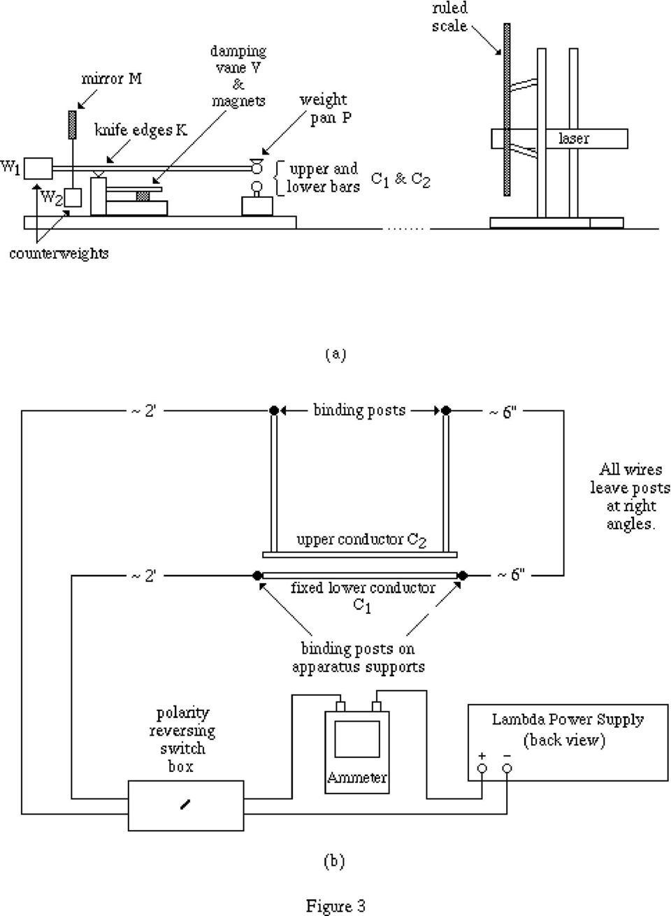
3 Experimental Purpose The purpose of this lab is to test the validity of equation (3). If equation (3) is valid, the following will be true: a. a plot of F vs I 2 will be a straight line with y-intercept equal to zero; and b. from the slope of the graph a value of µ o can be computed and will equal the accepted value of 12.57x10⁻⁷ webers/amp-m. Apparatus A schematic drawing of the apparatus to be used is shown in figure 3a on the next page. Current flows along the fixed straight conductor C 1 and back through the parallel conductor C 2. C 2 is part of a balance arm supported by the knife edges, the weight of the conductor being balanced by the adjustable rear counterweight W 1. The beam can be lifted off the knife edges by a beam lift (not shown in the diagram). The position of the lower counterweight W 2 determines the sensitivity of the balance: i.e. the deflection per unit force. The repulsive force due to the current is balanced by weights placed in the pan P, attached to C2. Oscillations of the beam are damped out by eddy currents in the metal vane V which moves in the field of a permanent magnet. The conductors can be aligned by loosening/tightening four thumbscrews (not shown in diagram). Changes in tilt of the balance are detected by reflecting a laser beam from the mirror M. The reflected beam falls on a ruled scale some distance (~2m) away. The laser intensity is reduced to a safe level by a filter which covers the output. DO NOT REMOVE THIS FILTER! Never look directly into the laser beam or look directly into the beam reflected from the mirror on the apparatus. The electrical circuit is shown schematically in figure 3b. (Note: This is not a plane view. C 2 is in fact directly above C 1 ). Current from the power supply is measured with the precision ammeter and passes through the conductors C 1 and C 2. The direction of the current can be reversed by the polarity reversing box. The wires connected to the binding post on the current balance have been arranged in such a way that the magnetic forces that they induce on C 2 and its supporting conductors are horizontal rather than vertical, since it's a vertical force that you're going to measure. The power supply itself generates a magnetic field, and is located as far from the balance as practical. (Why are these considerations important?) The power supply has two controls: "voltage" and "current" limitation, each with coarse and fine adjustment. To prevent error in reading the ammeter due to parallax, the ammeter has a mirror behind the needle. Use it. The meter should be on the 25A scale: check this. Check the zero, and if necessary adjust it, before you make measurements.

4
5 Procedure 1. Initial Setup. CAUTION: Always be very gentle with the balance. The knife edges are easily damaged and the conductors are easily bent. In particular, never drag the knife edges across their support. Use the beam lift when aligning the conductors. a. Adjust C 2 so that it is parallel to and vertically above C 1. To align the bars and to examine them for straightness, place a small coin on the weight pan to bring the bars into contact, but without distortion. Thumb screws on each front post permit either end of the lower bar to be raised or lowered. Similar thumb screws on each block at the rear permit either end of the upper bar to be moved forward or backward. The bars should be aligned as accurately as can be determined by the unaided eye when viewed from the front and from the top. When viewed from the front with a white sheet of paper behind the bars, the two bars may appear to be slightly lacking in straightness. If this is very serious, see Jan Largent (220 Wilder). Do not try to straighten the bars yourself. It is almost impossible to get them so straight that no light may be seen between them, but perfect straightness is not essential to the attainment of good quantitative results. b. Adjust the apparatus until the period of oscillation of the upper bar is 1-2 seconds and the time it takes for the upper conductor to stop moving is seconds. Start this step by gently putting the upper conductor into motion and measuring these parameters. In most cases, you will find the apparatus already adjusted to meet the stated conditions. If it is not, use counterpoise W 2 to adjust the period of oscillation and change the separation of the poles of the damping magnets adjust the time it takes for C 2 to come to rest. c. Adjust the position of the laser and the mirror tilt until the laser beam strikes the mirror and reflects onto the ruled portion of the scale. The beam from the laser is rectangular in shape. Position measurements using the ruled scale are much easier to make if the long axis of the beam is parallel to the lines on the ruled scale. If the long axis is not parallel to the lines on the scale, simply rotate the laser in its holder until this condition is met. Gently put the upper conductor into motion and ensure that the beam remains aligned with the ruled scale as it oscillates. Gently place a coin on the pan and record the laser beam position on the ruled scale. Wait a minute or two to check that the spot is steady. If it drifts, find out why. Probably the laser is inadequately secured. Remove the coin and, without disturbing the alignment, put a small piece of electrical tape on each end of the fixed conductor and at the center position under the pan so that the conductors cannot touch. You will have to remove this tape later, without disturbing the alignment, so don't make too permanent a job of it. d. Check for freedom of movement of the oscillating conductor. With C 2 at rest, record the position of the laser beam on the ruled scale. Gently cause the upper bar to oscillate.

6 When it stops again, record the rest position. If it deviates from the first observation, the knife-edges may not be clean, the base or table may be unsteady, or the balance or telescope may have been jarred. Check the equipment again and repeat this step until the two scale reading are the same. e. Set the controls on the power supply so only the current control needs to be used to adjust the current in the conductors. Turn the coarse (inner portion of control) and fine (outer portion of control) current control knobs on the power supply fully counterclockwise. Turn the coarse voltage control a half turn clockwise. This will ensure that the voltage control is inoperative in this experiment, and you can then control the current with the right hand knobs alone. This completes the initial adjustments. 2. Data Taking. CAUTION: Do NOT under any circumstances touch the apparatus when the power supply is providing current or allow the bars to touch. The former will seriously damage you and the latter will seriously damage the equipment. a. Adjust the position of the of the upper conductor until it is approximately one millimeter above the lower bar when it is at rest. Use W 1 to adjust the equilibrium separation of the two bars. Once this adjustment has been completes, place a small piece of electrical tape at the three positions on the lower bar. b. Calculate the separation d of the conductors. The separation of the two bars at equilibrium is determined as follows. Start by using the 2-meter stick to carefully measure the distance b between the mirror and the scale. Figure 4 Note the scale reading at equilibrium, depress the upper bar (by placing a coin on the scale
 and fine (outer portion of control) current control knobs on the power supply fully counterclockwise. Turn the coarse voltage control a half turn clockwise.")
7 pan) until it is in contact with the lower bar, and take a new scale reading. Simple geometry will show that the separation is d o = D a 2 b where D is the difference in readings, a is the mean distance from knife-edge to bar, and b is the distance from mirror to scale. Center to center distance d is obtained by adding the diameter of rods to d o. In this apparatus, a L = = (± ) m (± ) m diameter of rod = (±0.005) mm c. Make a series of F vs I measurements. Record the rest position of the laser beam on the ruled scale. Using forceps, place a 30 mg mass on the pan. Turn on the power supply and adjust the current to bring the laser beam back to its rest position. The repulsive magnetic force is then equal to the weight added. Reverse the current and repeat. By taking the average of the two values of the current you correct for the force on the conductor due the earth's and other stray magnetic fields. Repeat, increasing the weight by successive 30 mg increments, until the limit of the power supply (15A) is reached. Since I 1 = I 2 = I in (3), where I is the average current in the two directions, a plot of force F vs I 2 should be a straight line. Make the plot as you take the data. Does it go through the origin? Find the slope and thus deduce µo. Don't forget that d in (3) is the distance between the centers of the conductors. When you've finished, recheck the beam position for zero weight and current. If it has changed by a small amount (not more than 2 mm), correct your data on the assumption that the drift has been linear in time. To do this you will need to calibrate the scale in terms of weight on the scale: since the correction is small a rough calibration is sufficient. If the drift is larger than ~2 mm, find and eliminate its cause and repeat the experiment. Repeat the experiment for at least two larger separations of the conductors, going up to about 1 cm. You will probably find that as the separation increases your results get less accurate. Why is this? Make an estimate of the systematic errors in this experiment. When you have finished, remove the tape CAREFULLY and recheck the zero position of the laser spot. If necessary, correct your values of d on the assumption of linear zero drift.

8 Lab Report Your lab report should be a record of what you did in the lab. It should include a short explanation of what you were trying to do, any deviations from the stated procedure, all raw data, and any conclusions your can draw from the data. Also include the following: a. a plot of F vs I 2 for each different equilibrium setting; b. a computation of µ o from the slope of the graph of the F vs I 2 graph and equation (3); and c. a computation of the speed of light from the experimental values of ε o and µ o. Other questions you may wish to consider are: How does the lower counterweight (W 2 ) controls the sensitivity of the balance? How does reversing the current and averaging the result eliminate the error due to the earth's magnetic field? Show that the force (due to the current in C 1 ) on the sides of the frame which supply C 2 with current is horizontal and therefore does not introduce error into the measurement if C 1 is infinitely long.

Pre-lab Quiz/PHYS 224 Magnetic Force and Current Balance. Your name Lab section
 Pre-lab Quiz/PHYS 224 Magnetic Force and Current Balance Your name Lab section 1. What do you investigate in this lab? 2. Two straight wires are in parallel and carry electric currents in opposite directions
Experiment #9, Magnetic Forces Using the Current Balance
 Physics 182 - Fall 2014 - Experiment #9 1 Experiment #9, Magnetic Forces Using the Current Balance 1 Purpose 1. To demonstrate and measure the magnetic forces between current carrying wires. 2. To verify
The purposes of this experiment are to test Faraday's Law qualitatively and to test Lenz's Law.
 260 17-1 I. THEORY EXPERIMENT 17 QUALITATIVE STUDY OF INDUCED EMF Along the extended central axis of a bar magnet, the magnetic field vector B r, on the side nearer the North pole, points away from this
Physics 221 Experiment 5: Magnetic Fields
 Physics 221 Experiment 5: Magnetic Fields August 25, 2007 ntroduction This experiment will examine the properties of magnetic fields. Magnetic fields can be created in a variety of ways, and are also found
FORCE ON A CURRENT IN A MAGNETIC FIELD
 7/16 Force current 1/8 FORCE ON A CURRENT IN A MAGNETIC FIELD PURPOSE: To study the force exerted on an electric current by a magnetic field. BACKGROUND: When an electric charge moves with a velocity v
Experiment 3: Magnetic Fields of a Bar Magnet and Helmholtz Coil
 MASSACHUSETTS INSTITUTE OF TECHNOLOGY Department of Physics 8.02 Spring 2006 Experiment 3: Magnetic Fields of a Bar Magnet and Helmholtz Coil OBJECTIVES 1. To learn how to visualize magnetic field lines
E/M Experiment: Electrons in a Magnetic Field.
 E/M Experiment: Electrons in a Magnetic Field. PRE-LAB You will be doing this experiment before we cover the relevant material in class. But there are only two fundamental concepts that you need to understand.
Experiment 6: Magnetic Force on a Current Carrying Wire
 Chapter 8 Experiment 6: Magnetic Force on a Current Carrying Wire 8.1 Introduction Maricourt (1269) is credited with some of the original work in magnetism. He identified the magnetic force centers of
Ampere's Law. Introduction. times the current enclosed in that loop: Ampere's Law states that the line integral of B and dl over a closed path is 0
 1 Ampere's Law Purpose: To investigate Ampere's Law by measuring how magnetic field varies over a closed path; to examine how magnetic field depends upon current. Apparatus: Solenoid and path integral
Experiment 3: Magnetic Fields of a Bar Magnet and Helmholtz Coil
 MASSACHUSETTS INSTITUTE OF TECHNOLOGY Department of Physics 8.02 Spring 2009 Experiment 3: Magnetic Fields of a Bar Magnet and Helmholtz Coil OBJECTIVES 1. To learn how to visualize magnetic field lines
Physics 112 Homework 5 (solutions) (2004 Fall) Solutions to Homework Questions 5
 (2004 Fall) Solutions to Homework Questions 5") Solutions to Homework Questions 5 Chapt19, Problem-2: (a) Find the direction of the force on a proton (a positively charged particle) moving through the magnetic fields in Figure P19.2, as shown. (b) Repeat
Solutions to Homework Questions 5 Chapt19, Problem-2: (a) Find the direction of the force on a proton (a positively charged particle) moving through the magnetic fields in Figure P19.2, as shown. (b) Repeat
6/2016 E&M forces-1/8 ELECTRIC AND MAGNETIC FORCES. PURPOSE: To study the deflection of a beam of electrons by electric and magnetic fields.
 6/016 E&M forces-1/8 ELECTRIC AND MAGNETIC FORCES PURPOSE: To study the deflection of a beam of electrons by electric and magnetic fields. APPARATUS: Electron beam tube, stand with coils, power supply,
Review Questions PHYS 2426 Exam 2
 Review Questions PHYS 2426 Exam 2 1. If 4.7 x 10 16 electrons pass a particular point in a wire every second, what is the current in the wire? A) 4.7 ma B) 7.5 A C) 2.9 A D) 7.5 ma E) 0.29 A Ans: D 2.
Magnetic Field of a Circular Coil Lab 12
 HB 11-26-07 Magnetic Field of a Circular Coil Lab 12 1 Magnetic Field of a Circular Coil Lab 12 Equipment- coil apparatus, BK Precision 2120B oscilloscope, Fluke multimeter, Wavetek FG3C function generator,
1. Units of a magnetic field might be: A. C m/s B. C s/m C. C/kg D. kg/c s E. N/C m ans: D
 Chapter 28: MAGNETIC FIELDS 1 Units of a magnetic field might be: A C m/s B C s/m C C/kg D kg/c s E N/C m 2 In the formula F = q v B: A F must be perpendicular to v but not necessarily to B B F must be
Experiment #8: Magnetic Forces
 Experiment #8: Magnetic Forces Purpose: To study the nature of magnetic forces exerted on currents. Equipment: Magnet Assembly and Stand Set of Current Loop PC oards Triple-Arm Pan alance 0 15 V dc Variable
Determination of g using a spring
 INTRODUCTION UNIVERSITY OF SURREY DEPARTMENT OF PHYSICS Level 1 Laboratory: Introduction Experiment Determination of g using a spring This experiment is designed to get you confident in using the quantitative
Eðlisfræði 2, vor 2007
 [ Assignment View ] [ Pri Eðlisfræði 2, vor 2007 28. Sources of Magnetic Field Assignment is due at 2:00am on Wednesday, March 7, 2007 Credit for problems submitted late will decrease to 0% after the deadline
F B = ilbsin(f), L x B because we take current i to be a positive quantity. The force FB. L and. B as shown in the Figure below.
, L x B because we take current i to be a positive quantity. The force FB. L and. B as shown in the Figure below.") PHYSICS 176 UNIVERSITY PHYSICS LAB II Experiment 9 Magnetic Force on a Current Carrying Wire Equipment: Supplies: Unit. Electronic balance, Power supply, Ammeter, Lab stand Current Loop PC Boards, Magnet
PHYSICS 176 UNIVERSITY PHYSICS LAB II Experiment 9 Magnetic Force on a Current Carrying Wire Equipment: Supplies: Unit. Electronic balance, Power supply, Ammeter, Lab stand Current Loop PC Boards, Magnet
1. The diagram below represents magnetic lines of force within a region of space.
 1. The diagram below represents magnetic lines of force within a region of space. 4. In which diagram below is the magnetic flux density at point P greatest? (1) (3) (2) (4) The magnetic field is strongest
Measurement of Charge-to-Mass (e/m) Ratio for the Electron
 Ratio for the Electron") Measurement of Charge-to-Mass (e/m) Ratio for the Electron Experiment objectives: measure the ratio of the electron charge-to-mass ratio e/m by studying the electron trajectories in a uniform magnetic
Measurement of Charge-to-Mass (e/m) Ratio for the Electron Experiment objectives: measure the ratio of the electron charge-to-mass ratio e/m by studying the electron trajectories in a uniform magnetic
Electron Charge to Mass Ratio Matthew Norton, Chris Bush, Brian Atinaja, Becker Steven. Norton 0
 Electron Charge to Mass Ratio Matthew Norton, Chris Bush, Brian Atinaja, Becker Steven Norton 0 Norton 1 Abstract The electron charge to mass ratio was an experiment that was used to calculate the ratio
The DC Motor. Physics 1051 Laboratory #5 The DC Motor
 The DC Motor Physics 1051 Laboratory #5 The DC Motor Contents Part I: Objective Part II: Introduction Magnetic Force Right Hand Rule Force on a Loop Magnetic Dipole Moment Torque Part II: Predictions Force
Modern Physics Laboratory e/m with Teltron Deflection Tube
 Modern Physics Laboratory e/m with Teltron Deflection Tube Josh Diamond & John Cummings Fall 2010 Abstract The deflection of an electron beam by electric and magnetic fields is observed, and the charge
Magnetic Fields and Their Effects
 Name Date Time to Complete h m Partner Course/ Section / Grade Magnetic Fields and Their Effects This experiment is intended to give you some hands-on experience with the effects of, and in some cases
Mapping the Magnetic Field
 I Mapping the Magnetic Field Mapping the Magnetic Field Vector Fields The electric field, E, and the magnetic field, B, are two examples of what are termed vector fields, quantities which have both magnitude
Chapter 22 Magnetism
 22.6 Electric Current, Magnetic Fields, and Ampere s Law Chapter 22 Magnetism 22.1 The Magnetic Field 22.2 The Magnetic Force on Moving Charges 22.3 The Motion of Charged particles in a Magnetic Field
Mechanics. Determining the gravitational constant with the gravitation torsion balance after Cavendish. LD Physics Leaflets P1.1.3.1.
 Mechanics Measuring methods Determining the gravitational constant LD Physics Leaflets P1.1.3.1 Determining the gravitational constant with the gravitation torsion balance after Cavendish Measuring the
Physics 3 Summer 1989 Lab 7 - Elasticity
 Physics 3 Summer 1989 Lab 7 - Elasticity Theory All materials deform to some extent when subjected to a stress (a force per unit area). Elastic materials have internal forces which restore the size and
Prelab Exercises: Hooke's Law and the Behavior of Springs
 59 Prelab Exercises: Hooke's Law and the Behavior of Springs Study the description of the experiment that follows and answer the following questions.. (3 marks) Explain why a mass suspended vertically
GENERAL SCIENCE LABORATORY 1110L Lab Experiment 5 THE SPRING CONSTANT
 GENERAL SCIENCE LABORATORY 1110L Lab Experiment 5 THE SPRING CONSTANT Objective: To determine the spring constant of a spiral spring Apparatus: Pendulum clamp, aluminum pole, large clamp, assorted masses,
ELECTRIC FIELD LINES AND EQUIPOTENTIAL SURFACES
 ELECTRIC FIELD LINES AND EQUIPOTENTIAL SURFACES The purpose of this lab session is to experimentally investigate the relation between electric field lines of force and equipotential surfaces in two dimensions.
Experiment 5: Magnetic Fields of a Bar Magnet and of the Earth
 MASSACHUSETTS INSTITUTE OF TECHNOLOGY Department of Physics 8.02 Spring 2005 Experiment 5: Magnetic Fields of a Bar Magnet and of the Earth OBJECTIVES 1. To examine the magnetic field associated with a
Experiment 7: Forces and Torques on Magnetic Dipoles
 MASSACHUSETTS INSTITUTE OF TECHNOLOY Department of Physics 8. Spring 5 OBJECTIVES Experiment 7: Forces and Torques on Magnetic Dipoles 1. To measure the magnetic fields due to a pair of current-carrying
5. Measurement of a magnetic field
 H 5. Measurement of a magnetic field 5.1 Introduction Magnetic fields play an important role in physics and engineering. In this experiment, three different methods are examined for the measurement of
1. A wire carries 15 A. You form the wire into a single-turn circular loop with magnetic field 80 µ T at the loop center. What is the loop radius?
 CHAPTER 3 SOURCES O THE MAGNETC ELD 1. A wire carries 15 A. You form the wire into a single-turn circular loop with magnetic field 8 µ T at the loop center. What is the loop radius? Equation 3-3, with
Reflection and Refraction
 Equipment Reflection and Refraction Acrylic block set, plane-concave-convex universal mirror, cork board, cork board stand, pins, flashlight, protractor, ruler, mirror worksheet, rectangular block worksheet,
Magnetism. d. gives the direction of the force on a charge moving in a magnetic field. b. results in negative charges moving. clockwise.
 Magnetism 1. An electron which moves with a speed of 3.0 10 4 m/s parallel to a uniform magnetic field of 0.40 T experiences a force of what magnitude? (e = 1.6 10 19 C) a. 4.8 10 14 N c. 2.2 10 24 N b.
Physics 121 Sample Common Exam 3 NOTE: ANSWERS ARE ON PAGE 6. Instructions: 1. In the formula F = qvxb:
 Physics 121 Sample Common Exam 3 NOTE: ANSWERS ARE ON PAGE 6 Signature Name (Print): 4 Digit ID: Section: Instructions: Answer all questions 24 multiple choice questions. You may need to do some calculation.
MEASURING INSTRUMENTS. By: Nafees Ahmed, Asstt, Prof, EE Deptt, DIT, Dehradun
 MEASURING INSTRUMENTS By: Nafees Ahmed, Asstt, Prof, EE Deptt, DIT, Dehradun MEASURING INSTRUMENTS The device used for comparing the unknown quantity with the unit of measurement or standard quantity is
Force on Moving Charges in a Magnetic Field
 [ Assignment View ] [ Eðlisfræði 2, vor 2007 27. Magnetic Field and Magnetic Forces Assignment is due at 2:00am on Wednesday, February 28, 2007 Credit for problems submitted late will decrease to 0% after
Experiment 9. The Pendulum
 Experiment 9 The Pendulum 9.1 Objectives Investigate the functional dependence of the period (τ) 1 of a pendulum on its length (L), the mass of its bob (m), and the starting angle (θ 0 ). Use a pendulum
Interference. Physics 102 Workshop #3. General Instructions
 Interference Physics 102 Workshop #3 Name: Lab Partner(s): Instructor: Time of Workshop: General Instructions Workshop exercises are to be carried out in groups of three. One report per group is due by
Magnetic Force on a Current-Carrying Wire Warm Up
 Magnet Force on Current-1 Magnetic Force on a Current-Carrying Wire Warm Up 1. Forces on magnets Assume that we have a magnet of mass m 1 sitting on a scale (force meter 1), situation A. For this configuration
EXPERIMENT 7 OHM S LAW, RESISTORS IN SERIES AND PARALLEL
 260 7- I. THEOY EXPEIMENT 7 OHM S LAW, ESISTOS IN SEIES AND PAALLEL The purposes of this experiment are to test Ohm's Law, to study resistors in series and parallel, and to learn the correct use of ammeters
Fraunhofer Diffraction
 Physics 334 Spring 1 Purpose Fraunhofer Diffraction The experiment will test the theory of Fraunhofer diffraction at a single slit by comparing a careful measurement of the angular dependence of intensity
Chapter 27 Magnetic Field and Magnetic Forces
 Chapter 27 Magnetic Field and Magnetic Forces - Magnetism - Magnetic Field - Magnetic Field Lines and Magnetic Flux - Motion of Charged Particles in a Magnetic Field - Applications of Motion of Charged
Lab 8: Ballistic Pendulum
 Lab 8: Ballistic Pendulum Equipment: Ballistic pendulum apparatus, 2 meter ruler, 30 cm ruler, blank paper, carbon paper, masking tape, scale. Caution In this experiment a steel ball is projected horizontally
Lab 7: Rotational Motion
 Lab 7: Rotational Motion Equipment: DataStudio, rotary motion sensor mounted on 80 cm rod and heavy duty bench clamp (PASCO ME-9472), string with loop at one end and small white bead at the other end (125
Interferometers. OBJECTIVES To examine the operation of several kinds of interferometers. d sin = n (1)
") Interferometers The true worth of an experimenter consists in his pursuing not only what he seeks in his experiment, but also what he did not seek. Claude Bernard (1813-1878) OBJECTIVES To examine the
Interferometers The true worth of an experimenter consists in his pursuing not only what he seeks in his experiment, but also what he did not seek. Claude Bernard (1813-1878) OBJECTIVES To examine the
Rotational Motion: Moment of Inertia
 Experiment 8 Rotational Motion: Moment of Inertia 8.1 Objectives Familiarize yourself with the concept of moment of inertia, I, which plays the same role in the description of the rotation of a rigid body
Simple Harmonic Motion
 Simple Harmonic Motion 1 Object To determine the period of motion of objects that are executing simple harmonic motion and to check the theoretical prediction of such periods. 2 Apparatus Assorted weights
Phys222 Winter 2012 Quiz 4 Chapters 29-31. Name
 Name If you think that no correct answer is provided, give your answer, state your reasoning briefly; append additional sheet of paper if necessary. 1. A particle (q = 5.0 nc, m = 3.0 µg) moves in a region
Experiment 8: Undriven & Driven RLC Circuits
 Experiment 8: Undriven & Driven RLC Circuits Answer these questions on a separate sheet of paper and turn them in before the lab 1. RLC Circuits Consider the circuit at left, consisting of an AC function
Electricity. Confirming Coulomb s law. LD Physics Leaflets P3.1.2.2. 0909-Wie. Electrostatics Coulomb s law
 Electricity Electrostatics Coulomb s law LD Physics Leaflets Confirming Coulomb s law P3... Measuring with the force sensor and newton meter Objects of the experiments Measuring the force between two charged
EXPERIMENT: MOMENT OF INERTIA
 OBJECTIVES EXPERIMENT: MOMENT OF INERTIA to familiarize yourself with the concept of moment of inertia, I, which plays the same role in the description of the rotation of a rigid body as mass plays in
EXPERIMENT O-6. Michelson Interferometer. Abstract. References. Pre-Lab
 EXPERIMENT O-6 Michelson Interferometer Abstract A Michelson interferometer, constructed by the student, is used to measure the wavelength of He-Ne laser light and the index of refraction of a flat transparent
6. Block and Tackle* Block and tackle
 6. Block and Tackle* A block and tackle is a combination of pulleys and ropes often used for lifting. Pulleys grouped together in a single frame make up what is called a pulley block. The tackle refers
ACCELERATION DUE TO GRAVITY
 EXPERIMENT 1 PHYSICS 107 ACCELERATION DUE TO GRAVITY Skills you will learn or practice: Calculate velocity and acceleration from experimental measurements of x vs t (spark positions) Find average velocities
A Determination of g, the Acceleration Due to Gravity, from Newton's Laws of Motion
 A Determination of g, the Acceleration Due to Gravity, from Newton's Laws of Motion Objective In the experiment you will determine the cart acceleration, a, and the friction force, f, experimentally for
Physics Lab Report Guidelines
 Physics Lab Report Guidelines Summary The following is an outline of the requirements for a physics lab report. A. Experimental Description 1. Provide a statement of the physical theory or principle observed
E X P E R I M E N T 8
 E X P E R I M E N T 8 Torque, Equilibrium & Center of Gravity Produced by the Physics Staff at Collin College Copyright Collin College Physics Department. All Rights Reserved. University Physics, Exp 8:
Electromagnetic Induction: Faraday's Law
 1 Electromagnetic Induction: Faraday's Law OBJECTIVE: To understand how changing magnetic fields can produce electric currents. To examine Lenz's Law and the derivative form of Faraday's Law. EQUIPMENT:
Awell-known lecture demonstration1
 Acceleration of a Pulled Spool Carl E. Mungan, Physics Department, U.S. Naval Academy, Annapolis, MD 40-506; [email protected] Awell-known lecture demonstration consists of pulling a spool by the free end
MAG Magnetic Fields revised July 24, 2012
 MAG Magnetic Fields revised July 24, 2012 (You will do two experiments; this one (in Rock 402) and the Magnetic Induction experiment (in Rock 403). Sections will switch rooms and experiments half-way through
Conceptual: 1, 3, 5, 6, 8, 16, 18, 19. Problems: 4, 6, 8, 11, 16, 20, 23, 27, 34, 41, 45, 56, 60, 65. Conceptual Questions
 Conceptual: 1, 3, 5, 6, 8, 16, 18, 19 Problems: 4, 6, 8, 11, 16, 20, 23, 27, 34, 41, 45, 56, 60, 65 Conceptual Questions 1. The magnetic field cannot be described as the magnetic force per unit charge
Electromagnetism Laws and Equations
 Electromagnetism Laws and Equations Andrew McHutchon Michaelmas 203 Contents Electrostatics. Electric E- and D-fields............................................. Electrostatic Force............................................2
Objectives. Capacitors 262 CHAPTER 5 ENERGY
 Objectives Describe a capacitor. Explain how a capacitor stores energy. Define capacitance. Calculate the electrical energy stored in a capacitor. Describe an inductor. Explain how an inductor stores energy.
LABORATORY V MAGNETIC FIELDS AND FORCES
 LABORATORY V MAGNETIC FIELDS AND FORCES Magnetism plays a large part in our modern world's technology. Magnets are used today to image parts of the body, to explore the mysteries of the human brain, and
Faraday s Law of Induction
 Chapter 10 Faraday s Law of Induction 10.1 Faraday s Law of Induction...10-10.1.1 Magnetic Flux...10-3 10.1. Lenz s Law...10-5 10. Motional EMF...10-7 10.3 Induced Electric Field...10-10 10.4 Generators...10-1
Permanent Magnet Motor Kit, Magnetic Reed Type. (SKY-ReedMotorKit) Instructions
 Instructions") Permanent Magnet Motor Kit, Magnetic Reed Type (SKY-ReedMotorKit) Instructions This kit contains powerful permanent magnets. Exercise caution when handling them as they can pull on iron tools and snap
Permanent Magnet Motor Kit, Magnetic Reed Type (SKY-ReedMotorKit) Instructions This kit contains powerful permanent magnets. Exercise caution when handling them as they can pull on iron tools and snap
Lab 3 - DC Circuits and Ohm s Law
 Lab 3 DC Circuits and Ohm s Law L3-1 Name Date Partners Lab 3 - DC Circuits and Ohm s Law OBJECTIES To learn to apply the concept of potential difference (voltage) to explain the action of a battery in
WAVELENGTH OF LIGHT - DIFFRACTION GRATING
 PURPOSE In this experiment we will use the diffraction grating and the spectrometer to measure wavelengths in the mercury spectrum. THEORY A diffraction grating is essentially a series of parallel equidistant
Alignement of a ring cavity laser
 Alignement of a ring cavity laser 1 Introduction This manual describes a procedure to align the cavity of our Ti:Sapphire ring laser and its injection with an Argon-Ion pump laser beam. The setup is shown
Experiment: Static and Kinetic Friction
 PHY 201: General Physics I Lab page 1 of 6 OBJECTIVES Experiment: Static and Kinetic Friction Use a Force Sensor to measure the force of static friction. Determine the relationship between force of static
Motion of Charges in Combined Electric and Magnetic Fields; Measurement of the Ratio of the Electron Charge to the Electron Mass
 Motion of Charges in Combined Electric and Magnetic Fields; Measurement of the Ratio of the Electron Charge to the Electron Mass Object: Understand the laws of force from electric and magnetic fields.
Physics 30 Worksheet #10 : Magnetism From Electricity
 Physics 30 Worksheet #10 : Magnetism From Electricity 1. Draw the magnetic field surrounding the wire showing electron current below. x 2. Draw the magnetic field surrounding the wire showing electron
EXPERIMENT 3 Analysis of a freely falling body Dependence of speed and position on time Objectives
 EXPERIMENT 3 Analysis of a freely falling body Dependence of speed and position on time Objectives to verify how the distance of a freely-falling body varies with time to investigate whether the velocity
Chapter 22: Electric Flux and Gauss s Law
 22.1 ntroduction We have seen in chapter 21 that determining the electric field of a continuous charge distribution can become very complicated for some charge distributions. t would be desirable if we
DIRECT CURRENT GENERATORS
 DIRECT CURRENT GENERATORS Revision 12:50 14 Nov 05 INTRODUCTION A generator is a machine that converts mechanical energy into electrical energy by using the principle of magnetic induction. This principle
Polarization of Light
 Polarization of Light References Halliday/Resnick/Walker Fundamentals of Physics, Chapter 33, 7 th ed. Wiley 005 PASCO EX997A and EX999 guide sheets (written by Ann Hanks) weight Exercises and weights
Physics 25 Exam 3 November 3, 2009
 1. A long, straight wire carries a current I. If the magnetic field at a distance d from the wire has magnitude B, what would be the the magnitude of the magnetic field at a distance d/3 from the wire,
Name Partners Date. Energy Diagrams I
 Name Partners Date Visual Quantum Mechanics The Next Generation Energy Diagrams I Goal Changes in energy are a good way to describe an object s motion. Here you will construct energy diagrams for a toy
Chapter 22: Electric motors and electromagnetic induction
 Chapter 22: Electric motors and electromagnetic induction The motor effect movement from electricity When a current is passed through a wire placed in a magnetic field a force is produced which acts on
Care and Use of the Compound Microscope
 Revised Fall 2011 Care and Use of the Compound Microscope Objectives After completing this lab students should be able to 1. properly clean and carry a compound and dissecting microscope. 2. focus a specimen
Teaching Time: One 25-minute period. Lesson Summary Students use iron filings to observe the 2 and 3- D field lines around a magnet.
 Lesson Summary Students use iron filings to observe the 2 and 3- D field lines around a magnet. Prior Knowledge & Skills Completed the lesson: The Earth as a Magnet: Exploring Interactions in Geospace
AP2 Magnetism. (c) Explain why the magnetic field does no work on the particle as it moves in its circular path.
 Explain why the magnetic field does no work on the particle as it moves in its circular path.") A charged particle is projected from point P with velocity v at a right angle to a uniform magnetic field directed out of the plane of the page as shown. The particle moves along a circle of radius R.
A charged particle is projected from point P with velocity v at a right angle to a uniform magnetic field directed out of the plane of the page as shown. The particle moves along a circle of radius R.
GENERAL SCIENCE LABORATORY 1110L Lab Experiment 6: Ohm s Law
 GENERAL SCIENCE LABORATORY 1110L Lab Experiment 6: Ohm s Law OBJECTIVES: To verify Ohm s law, the mathematical relationship among current, voltage or potential difference, and resistance, in a simple circuit.
Torque and Rotary Motion
 Torque and Rotary Motion Name Partner Introduction Motion in a circle is a straight-forward extension of linear motion. According to the textbook, all you have to do is replace displacement, velocity,
If you put the same book on a tilted surface the normal force will be less. The magnitude of the normal force will equal: N = W cos θ
 Experiment 4 ormal and Frictional Forces Preparation Prepare for this week's quiz by reviewing last week's experiment Read this week's experiment and the section in your textbook dealing with normal forces
Edmund Li. Where is defined as the mutual inductance between and and has the SI units of Henries (H).
.") INDUCTANCE MUTUAL INDUCTANCE If we consider two neighbouring closed loops and with bounding surfaces respectively then a current through will create a magnetic field which will link with as the flux passes
INDUCTANCE MUTUAL INDUCTANCE If we consider two neighbouring closed loops and with bounding surfaces respectively then a current through will create a magnetic field which will link with as the flux passes
Currents and Magnetism
 About this lab: Currents and Magnetism Oersted's experiments, using a relatively simple instrument, were enough to rock the foundations of Newtonian Mechanics. The nature of magnetic force was distinct
Name Class Date Laboratory Investigation 4B Chapter 4: Cell Structure
 Name Class Date Laboratory Investigation 4B Chapter 4: Cell Structure The Microscope: A Tool of the Scientist You may refer to pages 66-67, 72-73 in your textbook for a general discussion of microscopes.
Electric Field Mapping Lab 3. Precautions
 HB 09-25-07 Electric Field Mapping Lab 3 1 Electric Field Mapping Lab 3 Equipment mapping board, U-probe, resistive boards, templates, dc voltmeter (431B), 4 long leads, 16 V dc for wall strip Reading
Candidate Number. General Certificate of Education Advanced Level Examination June 2010
 entre Number andidate Number Surname Other Names andidate Signature General ertificate of Education dvanced Level Examination June 1 Physics PHY4/1 Unit 4 Fields and Further Mechanics Section Friday 18
Experiments on the Basics of Electrostatics (Coulomb s law; Capacitor)
") Experiments on the Basics of Electrostatics (Coulomb s law; Capacitor) ZDENĚK ŠABATKA Department of Physics Education, Faculty of Mathematics and Physics, Charles University in Prague The physics textbooks
Experiments on the Basics of Electrostatics (Coulomb s law; Capacitor) ZDENĚK ŠABATKA Department of Physics Education, Faculty of Mathematics and Physics, Charles University in Prague The physics textbooks
IDEAL AND NON-IDEAL GASES
 2/2016 ideal gas 1/8 IDEAL AND NON-IDEAL GASES PURPOSE: To measure how the pressure of a low-density gas varies with temperature, to determine the absolute zero of temperature by making a linear fit to
ElectroMagnetic Induction. AP Physics B
 ElectroMagnetic Induction AP Physics B What is E/M Induction? Electromagnetic Induction is the process of using magnetic fields to produce voltage, and in a complete circuit, a current. Michael Faraday
Build A Simple Electric Motor (example #1)
") PHY115 Experiment 11 Build A Simple Electric Motor (example #1) MATERIAL This is the necessary equipment. Present any list of material in your written lab report. 1.5 V battery in series 1 ceramic magnet
PHY115 Experiment 11 Build A Simple Electric Motor (example #1) MATERIAL This is the necessary equipment. Present any list of material in your written lab report. 1.5 V battery in series 1 ceramic magnet
HOOKE S LAW AND OSCILLATIONS
 9 HOOKE S LAW AND OSCILLATIONS OBJECTIVE To measure the effect of amplitude, mass, and spring constant on the period of a spring-mass oscillator. INTRODUCTION The force which restores a spring to its equilibrium