SECTION INLETS INLET LOCATIONS
|
|
|
- Irma Preston
- 9 years ago
- Views:
Transcription
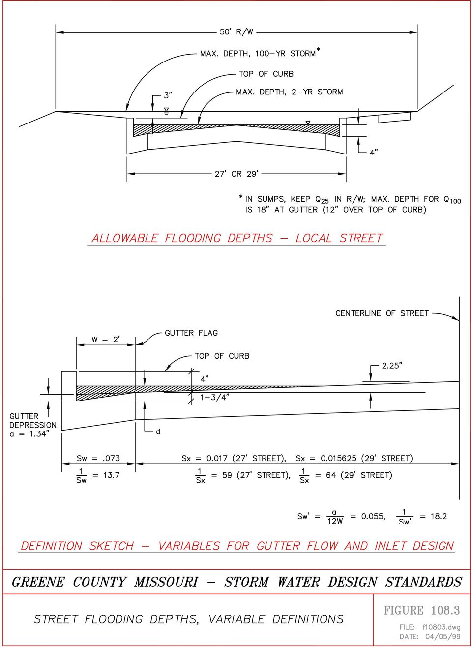
1 Greene County Design Standards -Adopted April 5, 1999 SECTION INLETS SECTION INLETS INLET LOCATIONS INLET INTERCEPTION CAPACITIES Clogging Factors INTERCEPTION AND BYPASS FLOW STANDARD INLET TYPES Curb Opening Inlets Area Inlets TYPES OF INLETS ALLOWED Public Streets Outside of Public Right-of-Way GENERAL SAFETY REQUIREMENTS REFERENCES Figure Figure Figure Figure Figure Figure Figure Figure Figure Figure Figure Figure Figure Figure Allowable Flooding Depths for Streets & Parking Lots Gutter Capacity for Greene County Standard 27' Wide Street Street Flooding Depths - Definition of Variables Curb Opening Inlets in Sumps - Definition of Variables Interception Capacity - Standard Curb Opening Inlet on Grade Interception Capacity of Standard Curb Opening Inlet in Sump Standard SS-5 Curb Opening Inlet SS-5 Inlet Riser Capacity Standard SS-6 Inlet Typical Reinforcement SS-5 & SS-6 Inlets Standard SS-6G Inlet Standard DI-1 Inlet Interception Capacity of Type DI-1 Inlet Typical Area Inlet Depression & Concrete Apron SECTION INLETS INLET LOCATIONS Inlets shall be provided at locations and intervals, and shall have a minimum inflow capacity such that maximum flooding depths set forth in Figure are not exceeded for the major or minor storm, Inlets shall be provided at all sump locations to prevent ponding of water. It is recommended that inlets be provided at street intersections upstream of pedestrian crosswalks. Gutter flow capacity for Greene County standard streets is shown in Figure INLET INTERCEPTION CAPACITIES Inlet capacities shall be determined in accordance with Federal Highway Administration HEC-12 (Reference 108.1) or HEC-22 (Reference 108.4). The gutter slope to be used for design of curb opening inlets located on vertical curves shall be the average gutter slope for a distance of twenty Greene County Design Standards - Adopted April 5, 1999 SECTION INLETS Page 1 of 6

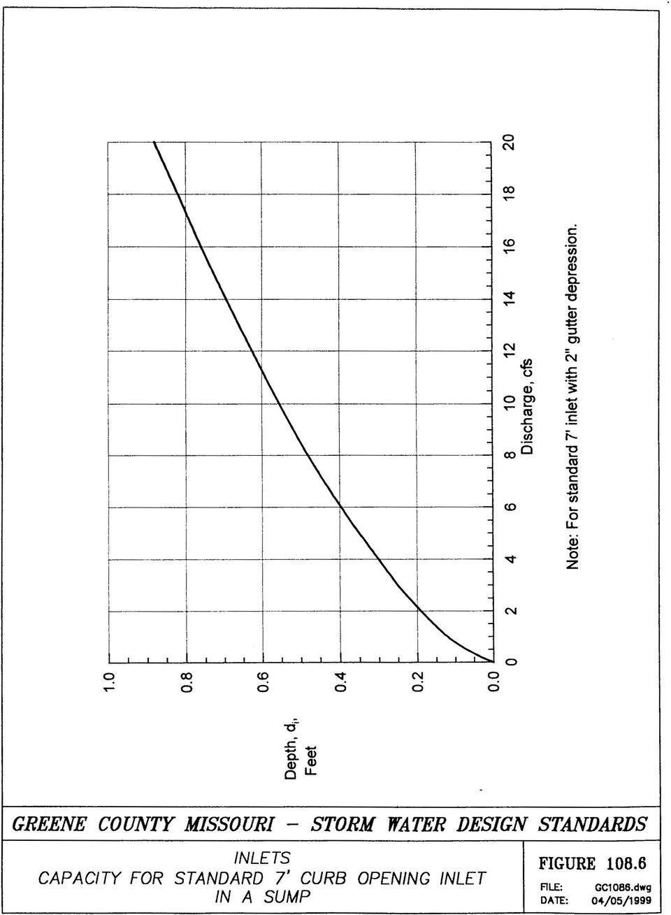
2 Greene County Design Standards -Adopted April 5, 1999 SECTION INLETS feet (20') upstream of the inlet. Variables for use in standard curb opening inlet computations are defined in Figures and Figures and show capacity charts for standard type SS-5 and SS-6 curb opening inlets on grades and in sumps. Nomographs and methods presented in the Neenah Inlet Grate Capacities report (Reference 108.2) may also be used where applicable. The use of commercial software utilizing the methods of HEC-12 or HEC-22 is acceptable Clogging Factors The inlet capacities determined as required in this section should be reduced as follows, in order to account for partial blockage of the inlet with debris (Reference 108.3): INLET TYPE & LOCATION CLOGGING FACTOR Standard (Type SS-5 & SS-6) Curb Opening Inlets on grades 0.9 in sumps 0.8 Open-side Drop Inlet (Type DI-1) in sumps 0.9 (not used on grades) --- Grated Inlets on grades 0.6 in sumps 0.5 Inlet lengths or areas shall be increased as required to account for clogging INTERCEPTION AND BYPASS FLOW It is generally not practical for inlets on slopes to intercept one hundred percent (100%) of the flow in gutters. Inlets must intercept sufficient flow to comply with street flooding depth requirements. Bypass flows shall be considered at each downstream inlet, until all flow has entered approved storm sewers or drainageways STANDARD INLET TYPES Curb Opening Inlets The standard curb opening used in Springfield and Greene County has been very successful. However, there has been a considerable amount of confusion over inlet nomenclature. The Greene County Design Standards - Adopted April 5, 1999 SECTION INLETS Page 2 of 6

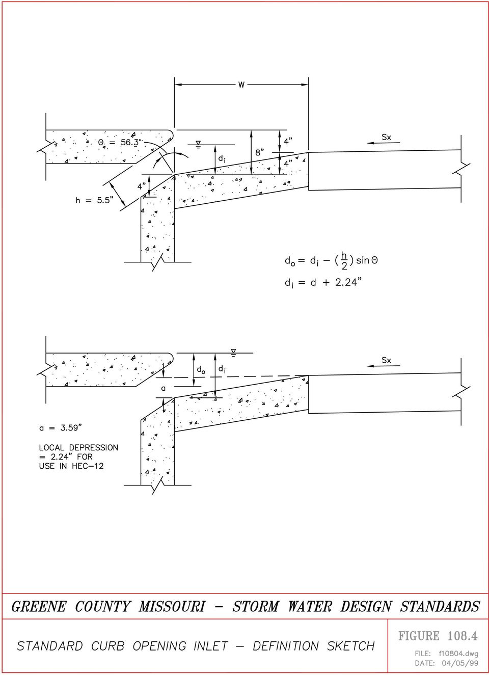
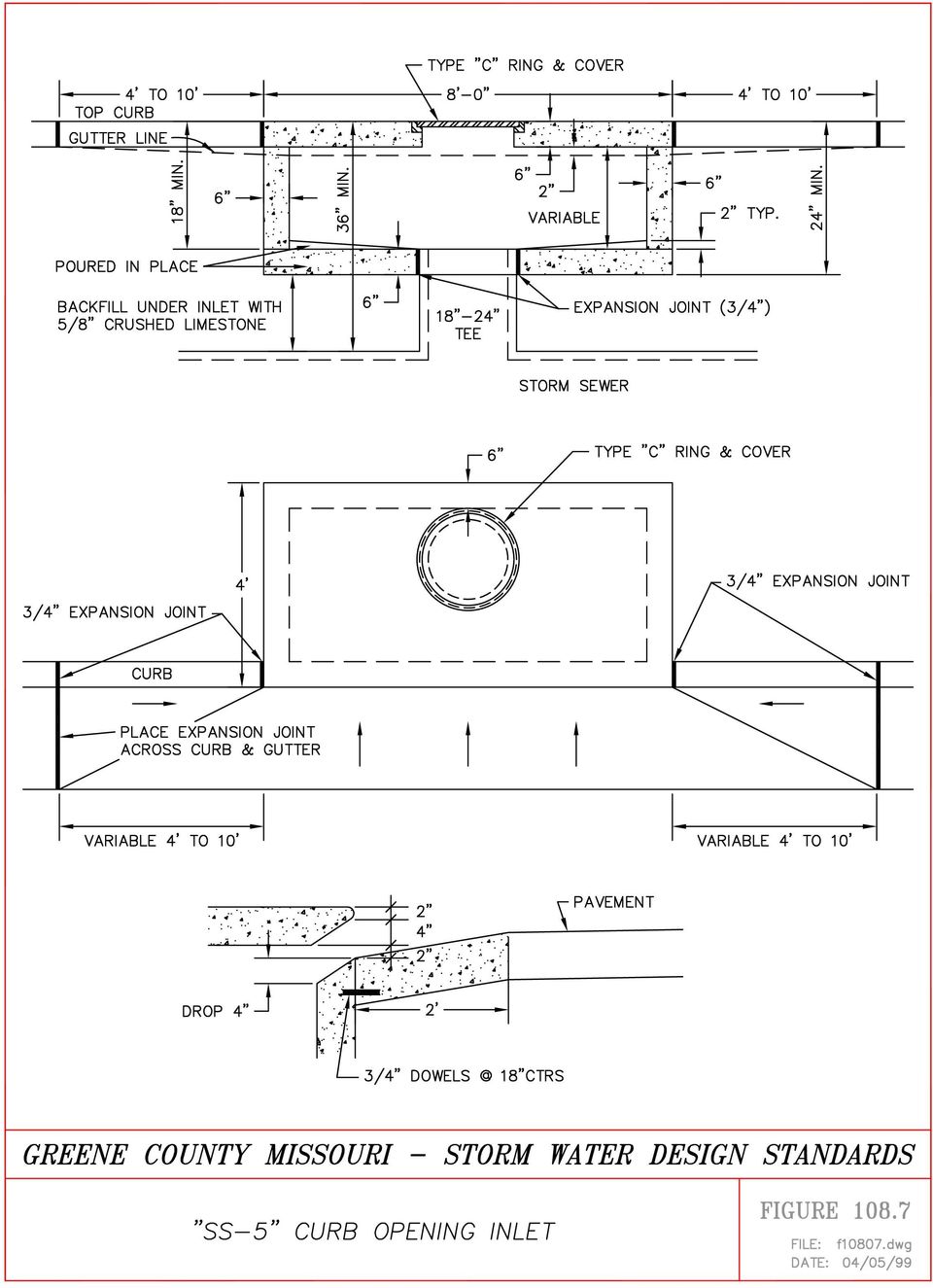
3 Greene County Design Standards -Adopted April 5, 1999 SECTION INLETS common designations used (SS-5, SS-6, etc.) are based upon the page number on which the standard inlets appeared in the City of Springfield Design Standards. It is the intention of these standards to maintain commonly used terms while clarifying inconsistencies and confusion. The following standard curb inlet designations are recommended for use in Greene County: A. SS-5 Inlet The standard SS-5 curb opening inlet shall refer to a shallow standard four foot by eight foot (4' x 8') curb opening inlet with a seven foot (7') long opening, located over a storm drain with a riser pipe connecting the inlet with the storm drain pipe. The type SS-5 inlet is shown in Figure Riser pipe capacities for use with SS-5 inlets are shown in Figure B. SS-6 Inlet SS-6 inlet shall refer to a full depth standard four foot by eight foot (4' x 8') curb opening inlet with a seven foot (7') long opening, which can also serve as a junction structure. The type SS-6 inlet is shown in Figure Precast SS-6 inlets may be provided with a six inch (6") precast top, known as a SS-6 top, or an eighteen inch (18") deep precast top, known as a SS-8 top (Figure ). The largest diameter pipe which can enter the short side of a SS-6 inlet is thirty inches (30"). C. SS-6S Inlet SS-6S inlet shall refer to a short SS-6 inlet, i.e. a full depth inlet with a four foot by four foot (4' x 4') exterior dimension and a three foot (3') long opening, which can also serve as a junction structure. SS-6S inlets are intended for use in sumps serving small areas. D. SS-6G Inlet SS-6G inlet shall refer to a SS-6 inlet modified to include a grate in the gutter. Grates used for SS-6G inlets shall be Deeter 2048L, Neenah R3076, or equal. Grates may not extend outward from the curb any further than the width of the standard gutter, which is two feet (2' ). Vanes shall be oriented in the direction of gutter flow. The type SS-6G inlet is shown in Figure E. Double Curb Inlets Where necessary to meet allowable flooding depth criteria, two (2) curb opening inlets may be placed side by side. An opening shall be provided in the common walls between the inlets to provide flow from one inlet to the other. The opening shall be a minimum of eighteen inches (18") high and shall extend the entire interior width of the inlet box. F. Construction Requirements Curb opening inlets may be constructed of either pre-cast or cast-in-place concrete. Cast-in-place concrete construction shall meet the requirements of Chapter VII of the City of Springfield Greene County Design Standards - Adopted April 5, 1999 SECTION INLETS Page 3 of 6

4 Greene County Design Standards -Adopted April 5, 1999 SECTION INLETS Technical Specifications for Public Works Construction. Reinforcement shall be as shown in the standard details included in this section. G. Special Inlet Box Designs Where necessary to accommodate large diameter pipes, curb opening inlets may be specially designed. Details of concrete dimensions and reinforcement shall be included in the drawings Area Inlets A. Open-Side Drop Inlets, Type DI-1 Open side drop inlets are intended for use in locations where open drainage channels, ditches, or swales terminate and flow enters the storm drain system, and flows range from ten (10) to one hundred (100) cubic feet per second. These inlets are preferred in order to minimize the risk of persons being swept into an open storm drain entrance. The standard type DI-1 inlet is shown in Figure This inlet has a four foot by four foot (4' x 4') exterior dimension and a maximum capacity of about eighteen (18) cfs per opening at a maximum allowable depth of two feet (2'). The designer must stipulate on the drawing the number of open sides to be provided, i.e., Type DI-1 w/2 sides open, etc. Interception capacity data for standard DI-1 inlets are shown in Figure Where additional capacity is needed, larger inlet structures can be used, provided dimensions are detailed on the drawings and interception capacity calculations are submitted. The maximum allowable opening height is six inches (6"). For greater opening heights, a horizontal bar shall be placed across the opening at maximum six inches (6") intervals. B. Grated Area Inlets Grated area inlets may be provided in parking lots and lawn areas. The maximum ponding depth over grated inlets shall be eighteen inches (18") for the major (100-year) storm. Concrete dimensions and reinforcement requirements for the inlet structure and the type of grate and frame to be used shall be specified on the drawings. Gratings shall be bicycle safe. It is recommended that a two inch (2") depression be provided for area inlets in paved parking areas in order to minimize standing water. It is also recommended that a reinforced concrete paving apron be provided for two feet (2') around the inlet in order to prevent pavement failure, and subsequent water ponding around the inlet (see Figure ). Greene County Design Standards - Adopted April 5, 1999 SECTION INLETS Page 4 of 6

5 Greene County Design Standards -Adopted April 5, 1999 SECTION INLETS TYPES OF INLETS ALLOWED Public Streets A. Curb Opening Inlets Standard curb opening inlets are required for use in public streets with curb and gutter. Curb openings are not permitted, except in situations where the drainage area is one-half (½) acre or less, and there is not sufficient grade to permit installation of a storm drain pipe. B. Grated Inlets In general, the use of grated inlets will not be permitted in streets, since these generally require adjustment when streets are re-paved. Where conditions are such that curb inlets cannot intercept the required rate of flow necessary to control street flooding depth or to provide diversion of flow to detention, sedimentation, or infiltration basins, combination grate and curb opening inlets (Type SS-6G) may be used provided that the width of the grate is no greater than the gutter width. "Trench inlets" with vaned grates may be specified with approval of the Stormwater Engineer and the Highway Administrator. Use of trench inlets will be permitted only when there is no practical alternative. Other types of inlets will not be permitted unless approved by the Stormwater Engineer and the Highway Administrator Outside of Public Right-of-Way The type of inlets specified outside of public right-of-way is left to the discretion of the designer provided the following criteria are met: 1) Maximum flooding depths for the major or minor storm as set forth in Figure are not exceeded. 2) General safety requirements set forth in Section are met GENERAL SAFETY REQUIREMENTS All inlet openings shall: 1) Provide for the safety of the public from being swept into the storm drainage system. The maximum allowable opening for standard curb opening inlets and open side drop inlets shall not exceed six inches (6") in height. The maximum bar spacing for grated inlets shall be six inches (6"). Where the height of the opening exceeds six inches (6"), a three-quarters inch (3/4") diameter galvanized steel bar, or other approved restriction shall be provided horizontally across the opening at mid-height, or at maximum intervals of six inches (6"). Greene County Design Standards - Adopted April 5, 1999 SECTION INLETS Page 5 of 6

6 Greene County Design Standards -Adopted April 5, 1999 SECTION INLETS The maximum open spacing between bars for grated inlets shall be six inches (6") in any direction. 2) Be sufficiently small to prevent entry of debris which would clog the storm drainage system. 3) Be sized and oriented to provide for safety of pedestrians, bicyclists, etc REFERENCES 1. "Drainage of Highway Pavements", Frank L. Johnson and Fred F. M. Chang, Hydraulic Engineering Circular No. 12, U.S. Department of Transportation, Federal Highway Administration, March Inlet Grate Capacities for Gutter Flow and Ponded Water, Jack M. Meyer, et al, Neenah Foundry Company, Neenah, Wisconsin, A Practical Approach to Designing Storm Sewer Systems. Dr. Ronald L. Rossmiller. Course notes for ASCE seminar of the same title. 4. Urban Drainage Design Manual, S.A. Brown, S.M. Stein, and J.C. Warner, Hydraulic Engineering Circular No.22, U.S. Department of Transportation, Federal Highway Administration, November m:\data\wp51\storm2\swregs\section 108.wpd Greene County Design Standards - Adopted April 5, 1999 SECTION INLETS Page 6 of 6

7 ALLOWABLE FLOODING DEPTHS FOR STREETS AND PARKING LOTS A. PUBLIC AND PRIVATE STREETS 1. MINOR/CONVENIENCE STORM: 2 year storm On grades: Local streets: No crown overtopping Collector streets: No overtopping, center 10' of street Secondary arterials: Two - 10' lanes must remain open; (T = 7.5' for 36'-wide street) Arterial streets : Flow limited to width of gutter (T=2') In sumps: Local streets: Depth shall not exceed top of curb Collector streets: Depth shall not exceed top of curb Secondary arterials: Two - 10' lanes must remain open; (Maximum spread, T = 7.5') Arterial streets: Flow limited to width of gutter (T=2') 2. MAJOR/EMERGENCY STORM On grades: All classifications: Limit 25-year storm to top of curb Limit 100-year storm to right-of-way Maximum depth, 100-year storm = 18" at face of curb. In sumps: All classifications: Limit 25-year storm to right-of-way Maximum depth, 100-year storm = 18" at face of curb. B. PARKING LOTS & PRIVATE DRIVES 1. MINOR/CONVENIENCE STORM - no requirements. 2. MAJOR/EMERGENCY STORM - depth shall be limited to 18" measured from the top of the grate or from the bottom of a vertical inlet opening. m:\data\wp51\storm2\swregs\section 108 figure wpd
 Arterial streets: Flow limited to width of gutter (T=2') 2.")
8

9
10
11

12
13
14

15
16
17
18
19

20

8.1.3 General Design Guidelines. The following guidelines shall be used when designing inlets along a street section:
 . Introduction Presented in this chapter are the criteria and methodology for design and evaluation of storm sewer inlets located in Town of Castle Rock. The review of all planning submittals will be based
STORM DRAINS CHAPTER 7
 CHAPTER 7 Chapter 7 - Storm Drains A storm drain is a drainage system that conveys water or stormwater, consisting of two or more pipes in a series connected by one or more structures. Storm drains collect
APPENDIX C INLETS. The application and types of storm drainage inlets are presented in detail in this Appendix.
 Storm Drainage 13-C-1 APPENDIX C INLETS 1.0 Introduction The application and types of storm drainage inlets are presented in detail in this Appendix. 2.0 Inlet Locations Inlets are required at locations
SECTION 08000 STORM DRAINAGE TABLE OF CONTENTS
 SECTION 08000 STORM DRAINAGE 08010 DESIGN A. Location B. Sizing TABLE OF CONTENTS 08020 MATERIALS A. Pipe Materials B. Structure Materials C. Installation D. Inlets and Outlets 08030 INSPECTIONS AND TESTING
CHAPTER 17: STORM SEWER STANDARDS. 17.00 Introduction. 17.01 Administration. 17.02 Standards 17.1
 CHAPTER 17: STORM SEWER STANDARDS 17.00 Introduction 17.01 Administration 17.02 Standards 17.1 17.00 INTRODUCTION The purpose of this chapter is to provide guidance for the design and construction of storm
DRAINAGE MANUAL CHAPTER VII STORM DRAINAGE SYSTEMS
 TDOT DESIGN DIVISION DRAINAGE MANUAL CHAPTER VII STORM DRAINAGE SYSTEMS August 1, 2012 CHAPTER 7 STORM DRAINAGE SYSTEMS SECTION 7.01 INTRODUCTION 7.01 INTRODUCTION...7-1 SECTION 7.02 DOCUMENTATION PROCEDURES
Storm Drainage Systems 11.9-1
 Storm Drainage Systems 11.9-1 11.9 Gutter Flow Calculations 11.9.1 Introduction Gutter flow calculations are necessary in order to relate the quantity of flow (Q) in the curbed channel to the spread of
APPENDIX D INLET CAPACITY AND SPACING. The capacity and spacing design of storm drainage inlets are presented in detail in this Appendix.
 Storm Drainage 3-D- PPENDIX D INET CPCITY ND SPCING.0 Introduction The capacity and spacing design of storm drainage inlets are presented in detail in this ppendix. 2.0 Design Recurrence Interval and Spread
CHAPTER 4. STORM SEWER SYSTEM DESIGN
 CHAPTER 4. CONTENTS Section Page ST- 1.0 OVERVIEW... 1 1.1 Purpose of the Chapter... 1 1.2 Chapter Summary... 1 2.0 STREET DRAINAGE... 2 2.1 Street Function and Classification... 2 2.2 Minor Storm Design
Drainage DR-701. Materials Field Sampling. Purpose of the Guidance Manual. General DR 701-1
 DR-701 Chapter Materials Field Sampling Drainage Subject INLETS INTRODUCTION & STORM SEWERS General Purpose of the Guidance Manual DR 701-1 STORM SEWER DEFINITION KYTC defines a storm sewer as two or more
CHAPTER 7 ROAD STORM DRAINAGE SYSTEMS
 CHAPTER 7 ROAD STORM DRAINAGE SYSTEMS Note: All questions and comments should be directed to the Hydraulics Unit Supervisor, Environmental Services Section. Revised November 2015 Road Storm Drainage Systems
City of La Quinta Public Works Department - Storm Drain Plan Review Checklist
 Tract or Parcel Project Name PCN Checked By Date City of La Quinta Public Works Department - Storm Drain Plan Review Checklist SUBMITTAL REQUIREMENTS Approved Tentative Tract Map Conditions of Approval
STREETS/INLETS/STORM SEWERS
 DRAINAGE CRITERIA MANUAL (V. 1) CONTENTS Section Page ST- 1.0 INTRODUCTION... 1 1.1 Purpose... 1 1.2 Urban Stormwater Collection and Conveyance Systems... 1 1.3 Components of Urban Stormwater Collection
Chapter 9 - Storm Drains
 Chapter 9 - Storm Drains TABLE OF CONTENTS CHAPTER 9 - STORM DRAINS... 9-1 9.1 Introduction... 9-1 9.1.1 Objective 9-1 9.2 Design Policy... 9-2 9.2.1 Definition 9-2 9.2.2 General Policies... 9-2 9.3 Design
Chapter Thirty-six... 5 36-1.0 OVERVIEW... 5 36-1.01 Introduction... 5 36-1.02 Inadequate Drainage... 5 36-2.0 POLICY AND GUIDELINES... 6 36-2.
 Chapter Thirty-six... 5 36-1.0 OVERVIEW... 5 36-1.01 Introduction... 5 36-1.02 Inadequate Drainage... 5 36-2.0 POLICY AND GUIDELINES... 6 36-2.01 Introduction... 6 36-2.02 Bridge Decks... 6 36-2.03 Curbs,
STANDARD SPECIFICATIONS & CONSTRUCTION DETAILS MANUAL SECTION 5 - STORM DRAINAGE. 5.01 Design
 SECTION 5 - STORM DRAINAGE 5.01 Design Storm drainage facilities shall be designed in accordance with the goals and guidelines set forth in the Unified Development Ordinance. The goal shall be to collect
SECTION 7- STORM SEWER
 SECTION 7- STORM SEWER 7.1. STORM SEWERS.... 7-1 7.2. SUMP DRAINS... 7-3 7.3. CATCH BASINS... 7-3 7.4. MANHOLES... 7-4 7.5. STORM SEWER CALCULATIONS... 7-4 7.6. CULVERTS AND BRIDGES... 7-5 7.7. OPEN CHANNELS...
CHAPTER 5. Storm Sewer
 CHAPTER 5 Storm Sewer A. Introduction All proposed developments shall have a properly designed and constructed storm water conveyance system. This chapter deals only with the conveyance system. Storm water
PUBLIC WORKS DESIGN, SPECIFICATIONS & PROCEDURES MANUAL LINEAR INFRASTRUCTURE
 REGION OF PEEL PUBLIC WORKS DESIGN, SPECIFICATIONS & PROCEDURES MANUAL LINEAR INFRASTRUCTURE Storm Sewer Design Criteria REVISED July 2009 PUBLIC WORKS STORM SEWER DESIGN CRITERIA TABLE OF CONTENTS 1.0
CHAPTER 4 STORM DRAINAGE SYSTEMS
 CHAPTER 4 STORM DRAINAGE SYSTEMS 4.1 Overview... 4-1 4.1.1 Introduction... 4-1 4.1.2 Inlet Definition... 4-1 4.1.3 Criteria... 4-1 4.2 Pavement Drainage... 4-2 4.2.1 Introduction... 4-2 4.2.2 Storm Drain
Table 4.9 Storm Drain Inlet Protetion Applicable for
 BMP C220: Storm Drain Inlet Protection Purpose To prevent coarse sediment from entering drainage systems prior to permanent stabilization of the disturbed area. Conditions of Use Type of Inlet Protection
Minimizes sediment and debris from entering storm drains that lead to waterways and watercourses.
 4.5-p DRAIN INLET PROTECTION Alternative Names: DI protection, Drop Inlet Protection DESCRIPTION Storm drain inlet (DI) protection slows and ponds stormwater, and filters sediment and debris before it
SECTION 6A STORM DRAIN DESIGN Mar. 2002 S E C T I O N 6A STORM DRAIN - DESIGN
 S E C T I O N 6A STORM DRAIN - DESIGN 6A.l Scope 6A.2 Storm Water Quantity 6A.3 Storm Drain Hydraulics 6A.4 Depths 6A.5 Locations 6A.6 Curved Storm Drains 6A.7 Manholes 6A.8 Catch basins 6A.9 Storm Drain
Index. protection. excavated drop inlet protection (Temporary) 6.50.1 6.51.1. Block and gravel inlet Protection (Temporary) 6.52.1
 6.50.1 6.51.1. Block and gravel inlet Protection (Temporary) 6.52.1") 6 Index inlet protection excavated drop inlet protection (Temporary) 6.50.1 HARDWARE CLOTH AND GRAVEL INLET PROTECTION Block and gravel inlet Protection (Temporary) sod drop inlet protection ROCK DOUGHNUT
6 Index inlet protection excavated drop inlet protection (Temporary) 6.50.1 HARDWARE CLOTH AND GRAVEL INLET PROTECTION Block and gravel inlet Protection (Temporary) sod drop inlet protection ROCK DOUGHNUT
CHAPTER 5 STORMWATER DRAINAGE SYSTEM DESIGN. Table of Contents SECTION 5.1 STORMWATER DRAINAGE DESIGN OVERVIEW
 CHAPTER 5 STORMWATER DRAINAGE SYSTEM DESIGN Table of Contents SECTION 5.1 STORMWATER DRAINAGE DESIGN OVERVIEW 5.1.1 Stormwater Drainage System Design...5-1 5.1.1.1 Introduction...5-1 5.1.1.2 Drainage System
CLARK COUNTY REGIONAL FLOOD CONTROL DISTRICT HYDROLOGIC CRITERIA AND DRAINAGE DESIGN MANUAL SECTION 800 STORM SEWER SYSTEMS TABLE OF CONTENTS
 CLARK COUNTY REGIONAL FLOOD CONTROL DISTRICT HYDROLOGIC CRITERIA AND DRAINAGE DESIGN MANUAL SECTION 800 STORM SEWER SYSTEMS TABLE OF CONTENTS 801 INTRODUCTION 803 802 DESIGN PARAMETERS 804 802.1 - Allowable
Stormwater Drainage Design for Parking Lots
 PDHonline Course C201 (4 PDH) Stormwater Drainage Design for Parking Lots 2012 PDH Online PDH Center 5272 Meadow Estates Drive Fairfax, VA 22030-6658 Phone & Fax: 703-988-0088 www.pdhonline.org www.pdhcenter.com
Chapter 7 Street, Inlets, and Storm Drains
 Chapter 7 Street, Inlets, and Storm Drains Contents 1.0 Introduction... 1 1.1 Purpose and Background... 1 1.2 Urban Stormwater Collection and Conveyance Systems... 1 1.3 System Components... 2 1.4 Minor
City of Shelbyville Site Inspection Checklist
 City of Shelbyville Site Inspection Checklist General Information Project Name: KYR10 Permit Number: Date: Project Location: Contractor: Conractor Representative: Inspector's Name: Title: Signature : Weather
Chapter 9 Storm Sewers
 Contents 1.0 Introduction... 1 2.0 Design Storms... 1 2.1 Minor Event... 1 2.2 Major Event... 1 3.0 Pipe Material and Size... 2 3.1 Pipe Material... 2 3.2 Minimum Pipe Size... 2 3.3 Service Life... 2 3.4
CHAPTER 13 STORM DRAINS
 CHAPTER 13 STORM DRAINS TABLE OF CONTENTS 13.1 OVERVIEW...3 13.1.1 Introduction...3 13.1.2 Symbols And Definitions...4 13.1.3 Concept Definitions...5 13.2 GENERAL DESIGN CRITERIA...7 13.2.1 Introduction...7
Storm Drain Inlet Protection
 Source: Caltrans Construction Site Best Management Practices Manual, 2003. Description Applications Installation and Implementation Requirements Devices installed at storm drain inlets to detain and/or
Local Road Assessment and Improvement Drainage Manual
 Local Road Assessment and Improvement Drainage Manual Donald Walker, T.I.C. Director, author Lynn Entine, Entine & Associates, editor Susan Kummer, Artifax, design Transportation Information Center University
SECTION 02530 STORM DRAINAGE STRUCTURES. 1. Trench excavation, backfill, and compaction; Section 02250.
 02530-1 of 5 SECTION 02530 STORM DRAINAGE STRUCTURES 02530.01 GENERAL A. Description Storm drainage structure construction shall include, but not necessarily be limited to, furnishing and installing or
SECTION 5: SANITARY SEWER SYSTEM DESIGN
 SECTION 5: SANITARY SEWER SYSTEM DESIGN 5.01 GENERAL Sanitary sewer improvements shall be designed to serve the ultimate level of City development as defined in the General Plan and the Wastewater Facilities
CHAPTER 3 STORM DRAINAGE SYSTEMS
 CHAPTER 3 STORM DRAINAGE SYSTEMS 3.7 Storm Drains 3.7.1 Introduction After the tentative locations of inlets, drain pipes, and outfalls with tail-waters have been determined and the inlets sized, the next
SECTION III DRAINAGE
 SECTION III DRAINAGE TOC-III.1 of 5 TABLE OF CONTENTS DRAINAGE FACILITIES No. Title D-1 Standard Underdrains D-2 Longitudinal Underdrain for Flexible Paving D-3 Spring Control Method & Detail D-4 Trench
Land Disturbance, Erosion Control and Stormwater Management Checklist. Walworth County Land Conservation Department
 Land Disturbance, Erosion Control and Stormwater Management Checklist Walworth County Land Conservation Department The following checklist is designed to assist the applicant in complying with the Walworth
DESCRIPTION OF STORMWATER STRUCTURAL CONTROLS IN MS4 PERMITS
 DESCRIPTION OF STORMWATER STRUCTURAL CONTROLS IN MS4 PERMITS Phase I MS4 permits require continuous updating of the stormwater system inventory owned and operated by the MS4. They also include inspection
ENGINEERING DESIGN GUIDELINES. for SUBDIVISIONS OR COMMERCIAL DEVELOPMENTS
 ENGINEERING DESIGN GUIDELINES for SUBDIVISIONS OR COMMERCIAL DEVELOPMENTS City of Birmingham Department of Planning, Engineering and Permits Engineering Division Office of the City Engineer 2008 TABLE
SECTION 5 - STORM DRAINS
 Drainage Criteria Manual SECTION 5 - STORM DRAINS 5.1.0 GENERAL This The purpose of this section discusses briefly is to consider the hydraulic aspects of storm drains and their appurtenances in a storm
CHAPTER 9 STORM DRAINAGE DESIGN AND STORMWATER QUALITY REGULATIONS
 June 27, 2011 Chapter 9 Storm Drainage Design and Stormwater Quality Regulations Table of Contents CHAPTER 9 STORM DRAINAGE DESIGN AND STORMWATER QUALITY REGULATIONS Table of Contents Chapter 9 Storm Drainage
CITY UTILITIES DESIGN STANDARDS MANUAL
 CITY UTILITIES DESIGN STANDARDS MANUAL Book 2 (SW) SW9 June 2015 SW9.01 Purpose This Chapter provides information for the design of open channels for the conveyance of stormwater in the City of Fort Wayne.
SEWER LINE EXTENSION DESIGN CHECKLIST
 SEWER LINE EXTENSION DESIGN CHECKLIST SWLE# Utilities Staff Date DISCLAIMER - This checklist is provided to Consulting Engineers for the express purpose of assisting them in compiling design plans for
Storm Drainage Design and Technical Criteria Manual. City of Brookings, SD
 Storm Drainage Design and Technical Criteria Manual City of Brookings, SD May, 2006 City of Brookings Storm Drainage Manual Ecological Resource Consultants, Inc. Storm Drainage Design and Technical Criteria
Drainage Design and Stormwater Pollution Prevention Manual
 , Texas Drainage Design and Stormwater Pollution Prevention Manual 2001 Teague Nall and Perkins, Inc. Engineers Consultants Fort Worth Irving Denton CITY OF DESOTO DRAINAGE DESIGN AND STORM WATER POLLUTION
Storm Drain Inlet Protection - IP
 Storm Drain Inlet Protection - IP DEFINITION A temporary protective device formed around a storm drain drop inlet to trap sediment. PURPOSE To prevent sediment from entering storm drainage systems, prior
DESCRIPTION OF WORK:
 DEPARTMENT OF PUBLIC WORKS COUNTY OF HENRICO P.O. BOX 27032 RICHMOND, VIRGINIA 23273 PERMIT NO. One (1) copy of application and four (4) copies of plans are hereby made to the Director of Public Works
2011 HYDRAULICS MANUAL
 STATE OF LOUISIANA DEPARTMENT OF TRANSPORTATION AND DEVELOPMENT P.O. Box 94245 Baton Rouge, Louisiana 70804-9245 http://www.dotd.la.gov/ HYDRAULICS MANUAL Hydraulics (225) 379-1306 PREFACE The following
Outlet stabilization structure
 Overview of Sedimentation and Erosion Control Practices Practice no. 6.41 Outlet stabilization structure Erosion at the outlet of channels, culverts, and other structures is common, and can cause structural
SE-10 STORM DRAIN INLET PROTECTION. Objectives
 STORM DRAIN INLET PROTECTION SE-10 Objectives Erosion Control - EC Sediment Control - SE Tracking Control - TC Wind Erosion Control - WE Non-Storm Water Management - NS Waste and Materials Management -
CITY OF VISTA STANDARD DRAWINGS (PRELIMINARY, FOR REVIEW)
") CITY OF VISTA STANDARD DRAWINGS (PRELIMINARY, FOR REVIEW) January, 2013 THIS SHEET INTENTIONALLY LEFT BLANK TABLE OF CONTENTS DRAINAGE STRUCTURES DRN-01 Corrugated metal pipe drop inlet DNR-02 Storm Drain
CITY OF VISTA STANDARD DRAWINGS (PRELIMINARY, FOR REVIEW) January, 2013 THIS SHEET INTENTIONALLY LEFT BLANK TABLE OF CONTENTS DRAINAGE STRUCTURES DRN-01 Corrugated metal pipe drop inlet DNR-02 Storm Drain
Micromanagement of Stormwater in a Combined Sewer Community for Wet Weather Control The Skokie Experience
 Micromanagement of Stormwater in a Combined Sewer Community for Wet Weather Control The Skokie Experience Robert W. Carr 1 * and Stuart G. Walesh 2 1 Water Resources Modeling, LLC, 4144 S. Lipton Ave,
BMP-7. A sediment filter or an excavated impounding area around a storm drain drop inlet or curb inlet.
 BMP-7 BMP: STORM DRAIN INLET PROTECTION Definition A sediment filter or an excavated impounding area around a storm drain drop inlet or curb inlet. To prevent sediment from entering storm drainage systems
VERTICAL SPEED CONTROL DEVICES
 H-3.8 VERTICAL SPEED CONTROL DEVICES GENERAL 1. Description This standard identifies minimum requirements that shall be met for all Vertical Speed Control Devices in the design and construction of elements
Homeowner s Guide to Drainage
 Homeowner s Guide to Drainage a scottsdale homeowner s guide to drainage produced by the city of scottsdale s stormwater management division Transportation Department TABLE OF CONTENTS Introduction 2 Drainage
Engineering Specifications February, 2004 Schedule H to Bylaw 7452, Subdivision Bylaw Page 18
 Schedule H to Bylaw 7452, Subdivision Bylaw Page 18 3.4 Sanitary Sewers 3.4.1 Materials 3.4.1.1 The class and type of pipe and fittings, together with required class of bedding and trench widths, shall
Chapter 12 STORM DRAINAGE SYSTEMS SOUTH DAKOTA DRAINAGE MANUAL
 Chapter 12 STORM DRAINAGE SYSTEMS SOUTH DAKOTA DRAINAGE MANUAL October 2011 Table of Contents Section Page 12.1 OVERVIEW...12-1 12.1.1 Introduction...12-1 12.1.2 Inadequate Drainage...12-1 12.1.3 General
Chapter 13 - Storm Drainage Systems Publication 584 2010 Edition CHAPTER 13 STORM DRAINAGE SYSTEMS
 CHAPTER 13 STORM DRAINAGE SYSTEMS 13.0 OVERVIEW A. Introduction. This chapter provides guidance on storm drain design and analysis. The quality of a final inplace system depends upon careful attention
Storm Drain Inlet Protection
 Categories EC Erosion Control SE Sediment Control TC Tracking Control WE Wind Erosion Control Non-Stormwater NS Management Control Waste Management and WM Materials Pollution Control Legend: Primary Category
SECTION 5 DRAFTING STANDARDS
 SECTION 5 DRAFTING STANDARDS 1 SECTION FIVE TABLE OF CONTENTS Description Page TABLE OF CONTENTS... 5-2 GENERAL... 5-3 DRAFTING STANDARDS... 5-5 DRAFTING MINIMUM REQUIREMENTS HANDOUT... 5-8 2 GENERAL 1.
INDEX STORM DRAINAGE PRE-APPROVED NOTES, DESIGN CRITERIA, & PLANS
 INDEX STORM DRAINAGE POLICIES D-1 NOT USED D-2 Small Project Drainage Review Requirements D-3 Targeted and Full Drainage Review Requirements D-4 Prohibited and Allowed Discharges to the Storm Drainage
SECTION 33 41 13 PUBLIC STORM UTILITY DRAINAGE PIPING
 SECTION 33 41 13 PUBLIC STORM PART 1 - GENERAL 1.01 SECTION INCLUDES A. Storm drainage piping, fittings, and accessories at proposed station areas and locations other than under and immediately adjacent
Fabricated Drainage Products
 Fabricated Drainage Products Complete Drainage System Inline Drains are used At the beginning of a drain line Add a new water inlet to an existing drain line using a riser pipe and tee HARCO Surface Drainage
State of Illinois Department Of Transportation CONSTRUCTION INSPECTOR S CHECKLIST FOR STORM SEWERS
 State of Illinois Department Of Transportation CONSTRUCTION INSPECTOR S CHECKLIST FOR STORM SEWERS While its use is not required, this checklist has been prepared to provide the field inspector a summary
Storm Drain Inlet Protection
 Objectives EC Erosion Control SE Sediment Control TR Tracking Control WE Wind Erosion Control Non-Stormwater NS Management Control Waste Management and WM Materials Pollution Control Legend: Primary Objective
ARTICLE II STORM DRAINAGE. (From Ordinance No. 1987-17; August 4, 1987; Sections III through VIII)
") ARTICLE II STORM DRAINAGE (From Ordinance No. 1987-17; August 4, 1987; Sections III through VIII) SECTION 2.1 Standard Provisions Standard Provisions All construction for storm drainage in the development
ARTICLE II STORM DRAINAGE (From Ordinance No. 1987-17; August 4, 1987; Sections III through VIII) SECTION 2.1 Standard Provisions Standard Provisions All construction for storm drainage in the development
Storm Drain Inlet Protection for Construction Sites (1060)
") Storm Drain Inlet Protection for Construction Sites (1060) Wisconsin Department of Natural Resources Conservation Practice Standard I. Definition A temporary device installed in or around a storm drain
Storm Drain Inlet Protection for Construction Sites (1060) Wisconsin Department of Natural Resources Conservation Practice Standard I. Definition A temporary device installed in or around a storm drain
CHOOSING THE PROPER INLET GRATE
 CHOOSING THE PROPER INLET GRATE Adopting an inlet grate design requires an analysis of the functions the grate should perform. A designer must review the drainage requirements and then specify which functions
City of Denton. Drainage Design Criteria Manual
 City of Denton Drainage Design Criteria Manual July 26, 2013 Drainage Design Criteria Manual Table of Contents Section 1.0 Introduction... 1 1.1 Purpose... 1 1.2 Design Criteria... 1 1.3 Definitions...
SUMP PUMP. City of Ann Arbor & C O L L E C T I O N S Y S T E M G L O S S A R Y
 Foundation A foundation is the bottom part of a building. It s the element that anchors the building to the ground and transmits the building s gravity load directly to the earth. Water damage weakens
STANDARD AND SPECIFICATIONS FOR STORM DRAIN INLET PROTECTION
 STANDARD AND SPECIFICATIONS FOR STORM DRAIN INLET PROTECTION Design Criteria Drainage Area The drainage area for storm drain inlets shall not exceed one acre. The crest elevations of these practices shall
SECTION 02400 - STORM DRAIN SYSTEM
 SECTION 02400 - STORM DRAIN SYSTEM CONTENTS: Part 1 - General... 1 1.01 Work Included... 1 1.02 Related Requirements... 1 1.03 Reference Standards... 1 1.04 Quality Assurance... 1 1.05 Measurement And
Culvert and Drainage Inlet/Outlet Safety Guidelines
 Culvert and Drainage Inlet/Outlet Safety Guidelines Page 1 Culvert and Drainage Inlet/Outlet Safety Guidelines 1.0 Preface 1.1 The purpose of these standards is to identify general and specific requirements
FY11 Sanitary Sewer Main Rehab and Point Repair Bid Tabulation
 644-10-569 Page 1 of 9 1 FOR CLEANING AND TELEVISING EXISTING SEWERS, AS SPECIFIED, ANY REQUIRED CLEANING, ANY LOCATION, ANY LENGTH OF SEWER, COMPLETE IN PLACE, FOR VARIOUS PIPE DIAMETERS. A. EXISTING
DRAINAGE DESIGN MANUAL CITY OF DALLAS PUBLIC WORKS
 DRAINAGE DESIGN MANUAL CITY OF DALLAS PUBLIC WORKS MAY 1993 DRAINAGE DESIGN MANUAL ClN OF DALLAS PUBLIC WORKS MAY, 1993 TABLE OF CONTENTS SECTION I INTRODUCTION 1. PURPOSE 2. SCOPE 3. ORGANIZATION OF MANUAL
City of West Linn Public Works Design Standards 2010. Table of Contents
 City of West Linn Public Works Design Standards Table of Contents SECTION TWO STORM DRAIN REQUIREMENTS... 1 2.0000 STORM DRAINS... 1 2.0010 General Design Requirements...1 2.0011 Site Drainage Plans...2
CHAPTER 13 STORM DRAINAGE SYSTEMS
 CHAPTER 13 STORM DRAINAGE SYSTEMS UDOT Manual of Instruction Roadway Drainage (US Customary Units), Storm Drainage Systems 13.C-1 CHAPTER 13 TABLE OF CONTENTS 13.1 OVERVIEW...4 13.1.1 Introduction...4
STORM DRAINAGE DESIGN CRITERIA. City of Sheridan, Wyoming
 STORM DRAINAGE DESIGN CRITERIA City of Sheridan, Wyoming November 2006 Table of Contents Page 1. PURPOSE...1 2. DRAINAGE REPORT SUBMITTAL REQUIREMENTS...2 3. RAINFALL...3 3.1. MINOR AND MAJOR DRAINAGE
Construction Site Inspection Checklist for OHC000004 By making use of some simple Best Management Practices (BMPs) a construction site operator can
 a construction site operator can") Construction Site Inspection Checklist for OHC000004 By making use of some simple Best Management Practices (BMPs) a construction site operator can do his or her share to protect Ohio's water resources
Construction Site Inspection Checklist for OHC000004 By making use of some simple Best Management Practices (BMPs) a construction site operator can do his or her share to protect Ohio's water resources
FY08 SEWER POINT REPAIRS BID TABULATION
 6-07-831 Page 1 of 12 1 FOR CLEANING AND TELEVISING EXISTING SEWERS, AS SPECIFIED, ANY REQUIRED CLEANING, ANY LOCATION, ANY LENGTH OF SEWER, COMPLETE IN PLACE, FOR VARIOUS PIPE DIAMETERS. A. EXISTING "
VDOT 2001 Road and Bridge Standards Section 100 - Drainage Items
 VDOT 2001 Road and Bridge s Page Title EW-1 EW-1A 101.01 Endwall for Pipe Culverts 12" - 36" Circular and 23" X 14" - 53" X 34" Elliptical Pipes EW-1PC EW-1APC 101.02 Precast Endwall for Pipe Culverts
6-1 Introduction. 1. Storm drain that does not require pressure testing. 2. Lateral that does not require pressure testing.
 Chapter 6 Storm Drains 6-1 Introduction A storm drain (storm sewer) is a network of pipes that conveys surface drainage from a surface inlet or through a manhole, to an outfall. Storm drains are defined
Block and Gravel Inlet Protection (BIP)
") Block and Gravel Inlet Protection (BIP) Practice Description Block and gravel inlet protection is a sediment control barrier formed around a storm drain inlet by the use of standard concrete block and
Block and Gravel Inlet Protection (BIP) Practice Description Block and gravel inlet protection is a sediment control barrier formed around a storm drain inlet by the use of standard concrete block and
CHAPTER 14 SECTION 1
 SECTION 1 S SECTION 1 S JANUARY 6, 006 S CH14-100 SECTION 1 S TABLE OF CONTENTS SECTION 1 S 1.1 INTRODUCTION... CH14-103 1. HYDRAULIC DESIGN... CH14-104 1..1 ALLOWABLE STORM WATER CAPACITY...CH14-104 1..
CHAPTER II - STORM DRAINAGE
 CHAPTER II - STORM DRAINAGE 201 General 201.1 Use of Chapter II 201.2 Triggers for Drainage Report 201.3 Relationship to Chapter on Storm Water Quality 202 Design Guidelines 202.1 Hydrology 202.1.1 General
X Planning X Quality X Maintenance & Operations
 Delaware Department of Transportation Division of Transportation Solutions Design Guidance Memorandum Memorandum Number 1-20 Revised 1. Road Design Manual 2. Bridge Design Manual 3. Utilities Design Manual
APPENDIX B DESIGN GUIDELINES FOR APPROVED TREATMENT METHODS
 APPENDIX B DESIGN GUIDELINES FOR APPROVED TREATMENT METHODS PLANTER BOXES 1. Determine the impervious area contributing flow to the planter box (see Chapter 4.2). 2. Assumption: Typical soil infiltration
URBAN DRAINAGE CRITERIA
 URBAN DRAINAGE CRITERIA I. Introduction This division contains guidelines for drainage system design and establishes a policy for recognized and established engineering design of storm drain facilities
DESIGN & TECHNICAL CRITERIA STORM DRAINAGE JEFFERSON COUNTY, COLORADO PLANNING & ZONING DIVISION
 DESIGN & TECHNICAL CRITERIA STORM DRAINAGE JEFFERSON COUNTY, COLORADO PLANNING & ZONING DIVISION Storm Drainage Design & Technical Criteria Acknowledgements Preparation of this document involved the efforts
DIVISION 2 - SEWERAGE AND DRAINAGE SECTION 02720 - STORM DRAIN SYSTEMS PART 1 - GENERAL
 DIVISION 2 - SEWERAGE AND DRAINAGE SECTION 02720 - STORM DRAIN SYSTEMS PART 1 - GENERAL 1.01 DESCRIPTION A. Furnish and install all storm drains, including manholes, inlets, service lines and other appurtenant
Section 402. STORM SEWERS
 402.02 Section 402. STORM SEWERS 402.01. Description. This work consists of constructing storm sewers of the size and class required, including excavation, bedding, and backfill. 402.02. Materials. Provide
SUSTAINABLE URBAN DRAINAGE SYSTEMS
 overflow can lead into a permeable conveyance system to increase further the benefit and reduce the need for pipe systems. Pollutant removal rates have been shown to be high, with some pollutants being
STORMWATER DESIGN CRITERIA MANUAL
 STORMWATER DESIGN CRITERIA MANUAL SEPTEMBER 2007 COMMUNITY DEVELOPMENT DEPARTMENT City of Weatherford, Texas TABLE OF CONTENTS Foreword.... 3 Storm Water Management Policy.... 4 Definitions.... 5 1. Preliminary