STORMWATER DESIGN CRITERIA MANUAL
|
|
|
- Rosemary Foster
- 9 years ago
- Views:
Transcription
1 STORMWATER DESIGN CRITERIA MANUAL SEPTEMBER 2007 COMMUNITY DEVELOPMENT DEPARTMENT City of Weatherford, Texas

2 TABLE OF CONTENTS Foreword Storm Water Management Policy Definitions Preliminary Drainage Plan Final Drainage Plan Hydrologic Analysis General Design Storm Requirements Street and Gutter Capacity Inlets Closed Conduit Systems Culverts, Bridges and Channels Storage Facilities Easements Flood Study References Appendix A, Street Flow Capacity Graphs Appendix B, Drainage Plan Checklist List of Tables Minimum Design Frequency 9 Runoff Coefficients (C) 10 Rainfall Intensity 11 Minimum/Maximum t c for Most Upstream Inlet 14 Minimum Grades for Storm Drain Pipe. 23 Roughness Coefficients and Permissible Velocities.. 24 Frequencies for Coincidental Occurrences.. 27 Junction or Structure Coefficient of Loss.. 31 Head Loss Coefficients Due to Obstructions 32 Head Loss Coefficients Due to Sudden Enlargements and Contractions 33 Culvert Inlet Coefficients. 37 Flood Study Matrix 48 List of Figures Average Velocities in Upland Areas.. 12 Average Velocities in Shallow Concentrated Flows 13 Inlets on Grade, Capacity Per Linear Foot of Opening.. 20 Inlets on Grade, Ratio of Intercepted Flow to Total Flow.. 21 Low Point Inlets, Capacity.. 22 Circular Pipe With Partial Flow.. 25 Minor Head Losses Due to Turbulence at Structures.. 29, 30 Storm Pipe Connection to Existing RCP 36 Pipe Collar Detail. 36 Gabion Mattress Attachment to Concrete Liner.. 40 Stage-Storage Curve.. 43 Stage-Discharge Curve.. 43
 10 Rainfall Intensity 11 Minimum/Maximum t c for Most Upstream Inlet 14 Minimum Grades for Storm Drain Pipe.")
3 FOREWORD The purpose of the Stormwater Design Criteria Manual is to present and explain hydraulic analysis and design criteria for storm water systems in the City of Weatherford and its extraterritorial jurisdiction. It is intended to provide guidelines for consistent storm water design in new development, redevelopment and remedial improvements projects. It is anticipated that this manual will not address every circumstance that may occur in urban storm water design. Coordination with City staff is recommended and encouraged during the planning, design and construction process.

4 CITY OF WEATHERFORD STORM WATER MANAGEMENT POLICY GOALS AND OBJECTIVES: 1. Establish and implement drainage policy and criteria to protect the general health, safety and welfare of the public. 2. Ensure adequate storm drainage and flood control. 3. Reduce flooding potential and excessive storm water runoff. 4. Minimize erosion and siltation problems. 5. Minimize the maintenance costs of constructed drainage facilities.

5 DEFINITIONS Adequate Outfall Storm drainage from a development must be carried to an adequate outfall or acceptable outfall. An adequate outfall is one that does not create adverse flooding or erosion conditions downstream and is in all cases subject to the approval of the Community Development Department. See Zone of Influence definition for the required conditions or criteria to determine the adequacy of an outfall from a proposed development. Drainage Studies and Downstream Assessment Studies of the proposed development and drainage areas, including a downstream assessment of properties that could be impacted by the development, will accompany the preliminary and final site plans. The Zone of Influence and adequate outfall point for the proposed development will be identified in the study and site plan. These studies will include adequate hydrologic analysis to determine the existing, proposed, and fully developed runoff for the drainage area that is affected by the proposed development. See Section 1 for additional description of these drainage studies. They will also include hydraulic studies that help define the Zone of Influence and any upstream or downstream offsite effects. The study, as part of the development site plan, shall address existing downstream, off-site drainage conveyance system(s) and define the drainage path from the outfall of the on-site water facilities, to the off-site drainage system(s) and/or appropriate receiving waters. It will include a capacity analysis of all existing constraint points such as existing floodplain developments, underground storm drainage systems, culverts, bridges, or channels from the point of storm water discharge of the development downstream to the limits of the Zone of Influence. Storms to be analyzed will be the 2-, 10-, and 100-year event. Zone of Influence and Parameters A Zone of Influence from a proposed development extends to a point downstream where the discharge from a proposed development no longer has a significant impact upon the receiving stream or storm drainage system. Downstream impacts due to a development must be analyzed and mitigated for the 2-, 10-, and 100-year floods for the entire Zone of Influence, as determined by the development engineer s analysis. The Zone of Influence for any proposed development must be identified by the development engineer, based on a drainage study that determines the specific location along the drainage route where no adverse impacts from the new development exist. A drainage study (see definition) will include the necessary hydrologic and hydraulic analyses to clearly demonstrate that the limits of the Zone of Influence have been identified, and that along the drainage route to that location, these parameters are met: No new or increased flooding of existing insurable (FEMA) structures (habitable buildings), No significant (0.1 ) increase in flood elevations over existing roadways for the 2-, 10-, and 100-year floods. No significant rise (0.1 or less) in 100-year flood elevations, unless contained in existing channel, roadway, drainage easement and/or R.O.W. No significant increase (maximum of 5%) in channel velocities for the 2-, 10-, and 100-year floods. Post-development channel velocities cannot be increased by more than 5% above pre-development velocities, nor exceed the applicable maximum permissible velocity shown in Table 7.1-B. If existing natural or vegetated channel velocities exceed six (6) feet per second, no additional increase in velocities will be allowed. No increases in downstream discharges caused by the proposed development that, in combination with existing discharges, exceeds the existing capacity of

6 the downstream storm drainage system. Evaluation of ditch and driveway culverts on rural roadways may be required. For watersheds of 100 acres or less at any proposed outfall, the downstream assessment may use the ten percent rule of thumb or a detailed study in order to determine the Zone of Influence. For all other watersheds, the Zone of Influence will be defined by a detailed hydrologic and hydraulic analysis.

7 STORM WATER DESIGN CRITERIA 1. PRELIMINARY DRAINAGE PLAN The preliminary drainage plan shall be conceptual in nature and shall show the watershed affecting the development and how the runoff from the fully developed watershed will be conveyed to, through, and from the development. It must comply with the standards outlined in the Subdivision Regulations and the drainage design criteria. Depending on the complexity of the development, detailed calculations may be required, including but not limited to evaluation of roadside ditches and adjacent floodplain. The preliminary drainage plan is a guide for the detailed drainage design. The review of the preliminary drainage plan does not constitute final drainage plan approval or authorize a variance to the Subdivision Regulations. 1.1 For any property involved in the development process, a preliminary drainage plan shall be provided for the proposed area of development. The plan shall be labeled as Preliminary and shall be signed, sealed, and dated by the engineer preparing the plan. 1.2 The preliminary drainage plan shall be at a scale not smaller than one inch equals 200 feet and shall include the following: Existing topography as shown by contour lines on two feet vertical intervals. Smaller vertical intervals may be required if the terrain warrants The boundary and size of each drainage area within and contributing to the property being developed shall be shown. The outline of drainage areas shall follow actual drainage features. Consideration shall be given to existing or anticipated features as modified by development The size and type of existing and proposed drainage facilities for both on-site and off-site facilities Proposed contours and flow arrows shall clearly indicate where and how the flow from drainage areas will be conveyed or intercepted Sufficient calculations based on the design criteria supporting the preliminary sizes and locations of drainage areas, facilities, and easements FEMA Flood Hazard Areas, if applicable Detailed off-site outfall information. This shall include the presence of existing or proposed drainage structures, bridges or systems; documentation of existing versus proposed developed site as well as ultimate runoff, identification of downstream properties which might be impacted by increased runoff, and proposed detention or other means of mitigation. Downstream impacts shall generally be delineated/identified to a point where the drainage from the proposed development has no impact on the receiving stream or on any downstream drainage systems within the Zone of Influence.

8 2. FINAL DRAINAGE PLAN A Final Drainage Plan for development of all or a portion (i.e. phase one or phase two, etc.) of the overall development shall be prepared and submitted with the final plans and specifications. This submittal shall include at a minimum: 2.1 Conformance with the Preliminary Drainage Plan. 2.2 Submission of detailed drainage calculations and detailed design plans. 2.3 Detailed hydrologic/hydraulic analysis for storage (detention) and outlet control structures. 2.4 Any required Corps of Engineer s Section 404 permits, Conditional Letters of Map Revision (CLOMR), Letters of Map Revision (LOMR) or other permits relating to lakes and streams required by any federal, state or local authorities. Requirements for permits from federal and state authorities should be initiated as early as possible to avoid delays in the development process. 3. HYDROLOGIC ANALYSIS 3.1 Rational Method, Q=CIA, shall be used for calculating peak runoff from watersheds of 200 acres or less. Use this method for the design of gutter flows, drainage inlets, storm sewer pipe, culverts and small ditches. The Rational Formula is expressed as follows: Q= CIA Where: Q = maximum rate of runoffs (cfs) C = runoff coefficient representing a ratio of runoff to rainfall I = average rainfall intensity for a duration equal to the tc (in/hr) A = drainage area contributing to the design location (acres) Table presents the Runoff Coefficient, C, for the standard zoning classification used by the City of Weatherford. Runoff shall be based on the fully developed watershed as depicted by the Future Land Use Plan found in the City of Weatherford s Comprehensive Plan Table shows the Rainfall Intensity, I, for Parker County. The values in the table are based on data from the Texas State Department of Highways and Public Transportation (now the Texas Department of Transportation, TXDOT). The data was adopted for use by the City of Weatherford in Time of Concentration, tc shall be based on fully developed conditions for the upstream watershed. The total time of concentration shall include overland and channelized flow. The maximum length allowed for the overland portion of the calculation is 50 feet. The remainder of the watershed shall be considered channelized flow. Refer to Figures 3.1-3A and 3.1-3B to determine the velocity which is used to calculate the time of concentration. For the most upstream inlet of the drainage system, minimum and maximum inlet times have been established based on land use. See Table 3.1-3C The following table shows the Minimum Design Frequency to be used when designing drainage facilities:
, Letters of Map Revision (LOMR) or other permits relating to lakes and streams required by any")
9 Type of Facility Minimum Design Frequency On-grade inlets 10 years w/100yr in ROW Low point inlets 25 years w/100yr positive overflow Storm sewer upstream of low pts 10 years Storm sewer downstream of low pts 25 years w/100yr positive overflow Street right-of-way 100 years* Channels and creeks 100 years Creek culverts and bridges 100 years Permanent bar ditch & assoc. culverts 5 years w/100 yr in ROW *Depending on the amount of flow in the right-of-way, additional drainage infrastructure may be required to reduce the flow in order to protect the health, safety and welfare of the general public The Drainage Area shall be based on fully developed areas within and contributing to the development, shall follow natural drainage features, and shall not be diverted. Existing or anticipated features modified by the development shall be considered when outlining drainage areas. A drainage area map shall be prepared that complies with the checklist in Appendix B.

10 RUNOFF COEFFICIENTS ( C ) Land Use Zoning Districts C Park, Undeveloped and Unimproved Areas 0.30 Park, Developed and Schools 0.40 SF-RR Single Family Rural Residential 0.45 SF-20 Single Family Estate 0.50 SF-11 Single Family 0.50 SF-8.4 Single Family 0.60 SF-6.5 Single Family 0.60 SF-PH Single Family Patio Homes 0.65 SF-L Single Family Licensed Lake Lots 0.50 SF-TH Single Family Townhomes F Two-Family Residential 0.80 MF-1 Residential Multi-family MF-2 Residential Multi-family NS Neighborhood Services 0.80 GR General Retail 0.80 CBD Central Business District 0.95 C Commercial 0.90 I Interstate 0.90 MU Mixed Use Varies by site plan LI Light Industrial 0.90 HI Heavy Industrial 0.90 Table 3.1-1

11 City of Weatherford, Parker County, Texas Duration Frequency, Return Period (Years) Hours Minutes Rainfall Intensity (inches per hour) Table 3.1-2: Intensity-Duration-Frequency of Precipitation based on TxDOT data for Parker County, TX 1990.

12
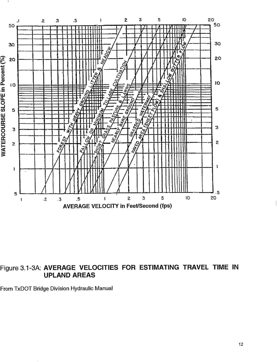
13

14 LAND USE MINIMUM TIME MAXIMUM TIME (minutes) (minutes) S.F. Residential, duplex, schools, parks Multi-Family, local business, commercial, industrial Central Business District Minimum time of concentration for the most upstream inlet (minimum inlet time). For anticipated upstream development, time of concentration should be no greater than the maximum. TABLE 3.1-3C Minimum/Maximum Time of Concentration for Most Upstream Inlet 3.2 Soil Conservation Service (SCS) Hydrologic Method can be used for estimating peak flows and generation of hydrographs for all design applications, including storm drain systems, culverts, open channels, energy dissipators, storage basins and outlet structures. This method is generally used for watersheds greater than 100 acres and less than 2000 acres The SCS hydrologic method is based on Rainfall-Runoff Equations and Runoff Curve Numbers (CN) influenced by hydrologic soil classification. Consideration is also given to the effects of urbanization on the natural soil group The SCS hydrologic method adopted in the City of Fort Worth s Storm Water Management Design Manual is an acceptable guide for application of this analysis method The simplified SCS method is not accepted by the City of Weatherford for final design calculations of runoff volume and peak rate discharges. 3.3 Snyder s Unit Hydrograph Method is used by the U.S. Army Corp of Engineers, Fort Worth District, for hydrologic studies. This method may be used for watersheds great than 100 acres Snyder s unit hydrograph method has also been adopted in the City of Fort Worth s Storm Water Design Manual and is acceptable as a guide for application of this analysis method. Additional sources detailing use of this method are Flood-Hydrograph Analysis and Computations, USACE Engineering Manual EM and the Flood Hydrology Manual, A Water Resources Technical Publication, The Bureau of Reclamation. 3.4 Downstream Evaluation is a procedure to protect properties from flood and erosion impacts due to upstream development. Timing of flow released from detention basins can sometimes combine with the peak flow of the natural drainageway in such a manner that actually increases the downstream peak discharge *Evaluation of the downstream impacts extends from the outfall of the proposed development to a point downstream identified by the Zone of Influence or an Adequate Outfall.
 Hydrologic Method can be used for estimating peak flows and generation of hydrographs for all design applications, including storm drain systems, culverts, open")
15 Zone of Influence extends to a point downstream where the discharge from a proposed development no longer has a significant impact upon the receiving stream or storm drainage system. Adequate Outfall is the location of acceptable outfall that does not create adverse flooding or erosion conditions downstream. These methods recognize the fact that a structural control providing detention has a Zone of Influence downstream where its effectiveness can be felt. Beyond this Zone of Influence, the storm water effects of a structural control become relatively small and insignificant compared to the runoff from the total drainage area at that point. Based on studies and master planning results for a large number of sites, a general rule of thumb is that the Zone of Influence can be considered to be the point where the drainage area controlled by the detention or storage facility comprises 10% of the total drainage area. This is known as the 10% Rule. As an example, if a structural control drains 10 acres, the Zone of Influence ends at the point where the total drainage area is 100 acres or greater. Typical steps in a downstream assessment include: 1. Determine the outfall location of the site and the pre- and postdevelopment site conditions. 2. Using a topographic map, determine a preliminary lower limit of the Zone of Influence (approximately 10% point). 3. Using a hydrologic model, determine the pre-development peak flows and velocities at each junction beginning at the development outfall and ending at the next junction beyond the 10% point. Undeveloped off-site areas are modeled as full buildout for both the pre- and post-development analyses. The discharges and velocities are evaluated for three storms: a. Streambank Protection storm, 2-year, 24-hour event b. Conveyance storm, 10-year, 24-hour event c. Flood Protection Storm, 100-year, 24 hour event 4. Change the land use on the site to post-development conditions and rerun the model. 5. Compare the pre- and post-development peak discharges and velocities at the downstream end of the model. If the postdeveloped flows are higher than the pre-developed flows for the same frequency event, or the post-developed velocities are higher than the allowable velocity of the downstream receiving system, extend the model downstream. Repeat steps 3 and 4 until the post-development flows are less than the pre-developed flows, and the post-developed velocities are below the allowable velocity. See the Table 7.1-B for allowable velocities. 6. If shown that no peak flow increases occur downstream and postdeveloped velocities are allowable, then the control of the flood protection volume may be waived by the City Engineer. 7. If peak discharges are increased due to development, or if downstream velocities are erosive, one of the following options is required: Document that existing downstream conveyance is adequate to convey post-developed storm water discharges (no erosion, no flooding). Reduce the flow elevation and/or velocity through channel or flow conveyance structure improvements downstream.

16 Design an on-site structural control facility such that the postdevelopment flows do not increase the peak flows, and the velocities are not erosive, at the outlet and the determined junction locations. *Evaluation of downstream impacts is from the NCTCOG Design Manual for Site Development, January GENERAL DESIGN STORM REQUIREMENTS Drainage design requirements for streets, closed systems, and open channels shall provide protection for property during a storm having a 100-year recurrence interval. The design shall assume a fully developed watershed (ultimate build out) for all areas contributing to the storm water flow. 4.1 Closed Conduit Systems shall be designed for a minimum 10-year storm with a combined capacity in the closed system and a surface drainage system (i.e. street) that will convey the 100-year storm. The 5-year storm must be within the permissible spread of water in the gutter. The 100-year storm flow must be contained within the ROW. The closed conduit HGL shall be at least two (2) feet below the top of curb and one (1) foot below curb line in inlets. The capacity of the underground system may be required to exceed the 10-year storm in order to satisfy the 100-year storm criteria (contained within the ROW). Adequate inlet capacity shall be provided to intercept surface flows before the ROW capacity is exceeded. 4.2 Low Point Inlets in sag or sump conditions shall be sized to intercept and convey the 25-year storm, provided that a positive overflow is constructed for the remainder of the 100-year storm. The positive overflow structure must be concrete or other acceptable non-earthen structure extending from the sump inlet to the storm sewer outfall. In the event that a structural overflow is not practical, then the underground system must be sized to convey the 100- year storm. 4.3 Culverts and Channels shall be sized to convey the 100-year storm for the fully developed watershed. 5. STREET AND GUTTER CAPACITY A roof top cross-section (uniform cross-slope, triangular gutter) shall be used for concrete streets. Asphaltic streets may be either roof top or parabolic crosssections. Pavement material and cross-section shall be designated on the plans. Field changes will not be allowed. See Appendix A for design requirements and maximum allowable flow in street right-of-way. 5.1 Permissible Spread of Water refers to the amount of water that is allowed to collect in streets during a 5-year storm event. In order that excess storm water will not collect in streets or thoroughfares during a design storm, the following spread of water values shall be used for the various types of streets Divided Arterials Permissible Spread of Water. The permissible spread of water in gutters of major divided thoroughfares shall be limited so that one traffic lane on each side remains clear during the 5-year storm. Gutter flow shall be based on storm duration of 10 minutes. The 100-year storm shall be contained within the ROW.
 for all areas contributing to the storm water flow. 4.")
17 Conditions. Recessed curb Inlets on arterials shall preferably be located at street intersections, low points of grade or where the gutter flow exceeds the permissible spread of water criteria. Inlets shall be located, when at all possible, on the side streets when grade permits. In no case shall the gutter depression at curb inlets exceed 4 inches. In super-elevated sections, curb inlets shall be placed against the center medians as needed to intercept gutter flow to prevent flow from crossing the thoroughfares on the surface in valley gutters or otherwise Minor Arterial B5 and Commercial Collector Streets C and C Permissible Spread of Water. The permissible spread of water in gutters shall be limited so that one standard lane of traffic will remain clear during the 5-year storm. The 100-year storm shall be contained within the ROW Conditions. Recessed curb inlets shall preferably be located at street intersections, low points of grade or where the gutter flow exceeds the permissible spread of water criteria. Inlets shall be located, when at all possible, on the side streets when grade permits. Recessed curb inlets shall be used on streets without parking lanes. Standard curb inlets may be used on streets where parking lanes are provided. In no case shall the gutter depression at curb inlets exceed 4 inches Local Streets (Residential A, B and D ) Permissible Spread of Water. The permissible spread of water for local streets shall be limited by height of the curb for 5-year storms. The 100-year storm shall be contained within the ROW Conditions. Inlets shall be located at street intersections, low points of grade or where the gutter flow exceeds the permissible spread of water criteria. Standard curb inlets (not recessed) shall be used in all cases. In no case shall the gutter depression at inlets exceed 4 inches Flow of water shall be evaluated at T intersections and short radius horizontal curves to prevent storm water overtopping the curbs. If extending storm sewer to the location is not a reasonable alternative in such an occurrence, a minimum finished floor elevation shall be established on affected lots based on a 100-year flow in the street Rural Streets (roadside ditch) Permissible Spread of Water. The roadside ditch shall be designed to convey the flow for the 100-year storm without leaving the right-of-way Culverts in Roadside Ditch. Culverts at roadway intersections shall be a minimum 24-inch diameter. Culverts at driveways shall be a minimum 18-inch diameter. Culverts shall be designed to carry the 5-year storm at a minimum. The driveway or roadway above the pipe shall have an invert or

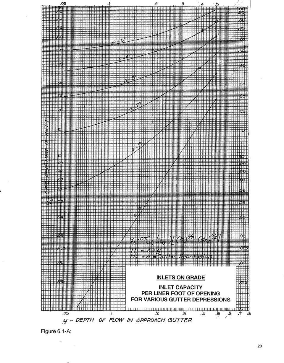
18 low point in the pavement for positive overflow. The culvert and pavement invert shall be designed to carry the 100-year storm. 5.2 Gutter Flow is based on Manning s Formula, Q= A R 2/3 S 1/2 where: n Q = gutter flow rate, cfs n = Manning s roughness coefficient A = cross-sectional area of the flow, sq. ft. R = hydraulic radius of the flow, ft (R = A/WP) WP = wetted perimeter of the flow area, ft. S = longitudinal slope of the gutter, ft/ft See Appendix A for design requirements and maximum allowable storm flow in street right-of-way. 6. INLETS Inlets are classified as on grade inlets and low point inlets. On grade inlets are either standard (in line) curb inlets or recessed curb inlets. Both standard and recessed inlets are constructed with a four-inch (4 ) gutter depression at the inlet opening. Grate inlets are not acceptable for use in the public storm drain system. 6.1 Curb Inlets on Grade with a depressed gutter have a design capacity based on the following equation: QL = 0.7 [1/(H1-H2)] [(H1) 5/2 (H2) 5/2 ] Where: QL = Discharge into inlet in c.f.s. per linear ft of opening H1 = a + y H2 = a= gutter depression in feet (4 = 0.33 ) Y = Depth of flow in approach gutter in feet The curve shown in Figure 6.1-A provides for the direct solution of the above equation when the value of Y is known. The curve shown in Figure 6.1-B provides for the determination of the ratio of the intercepted flow by the inlet to the total flow in the gutter. 6.2 Low Point Inlets (in sump) can be curb inlets on a street or drop inlets (y inlets) at off street locations. Low point inlets operate as a rectangular broadcrested weir at water depths within the opening height. The capacity is based on the following weir equation: Q = y 3/2 L or Q/L = 3.087y 3/2 Q = Inlet capacity in c.f.s Y = Head at the inlet in feet L = Length of inlet opening in feet The curves shown in Figure 6.2-C provide for direct solution of the above equation. Where the depth of water is such that the opening at the curb inlet or drop inlet is completely submerged, the proper orifice formula should be used in computing the discharge rather than the weir formula. The inlet operates as

19 an orifice at depths greater than 1.4 times the opening height. The flow is in transition between these two operational stages. Capacity of the orifice is based on the following equation: Q = 0.67 A (2gh) 1/2 Where: Q = Capacity of the opening in c.f.s A = Area of the opening in sq ft g = Acceleration due to gravity, 32.2 ft/sec 2 h = Depth of water to center of opening in ft. The curves for the orifice formula are also plotted on Figure 6.2-C with the corresponding curb inlet and drop inlet. The maximum capacity of the curb inlets at low points with submerged openings shall be limited to two (2) c.f.s. per linear foot of opening. 7. CLOSED CONDUIT SYSTEMS Closed systems shall be used when the flow can be carried in a 72-inch diameter pipe or smaller. The closed system shall be connected to an existing system or extended until it reaches an open channel or natural creek. Improvements will include appropriate transitions to the centerline of creeks, ditches or drainage channels of sufficient capacity to adequately serve the drainage area. 7.1 Minimum Velocities and Grades shall be sufficient to prevent excessive deposits of solid materials, otherwise objectionable clogging may result. The controlling velocity is near the bottom of the conduit and considerably less than the mean velocity of the sewer. Storm drains shall be designed to have an minimum mean velocity flowing full of 2.5 fps. Table 7.1-A indicates the minimum grades for concrete pipe (n = 0.013), flowing at 2.5 fps. Velocities in storm sewers are important mainly because of the possibilities of excessive erosion of the storm drain inverts. Table 7.1-B shows the desirable velocities for most storm drainage design. 7.2 Pipe Materials used in construction of the public storm drain system in the City of Weatherford shall be limited to reinforced concrete pipe (RCP). Generally, Class III RCP shall be used when the pipe cover is 3 feet to 13 feet. Class IV RCP is used when cover is 13 feet or less than 3 feet. Corrugated plastic pipe (profile wall with smooth interior), including High-Density Polyethylene (HDPE) pipe, corrugated PVC (CPVC) and CMP may be used in the following specific situations: HDPE, CPVC and CMP pipe is permitted for use as driveway culverts in roadside ditches. Minimum allowable size shall be 18 inches. Driveway permits will be required from the Community Development office. In no case shall any pipe material other than concrete be approved for installation under publicly maintained pavement. Where allowed, CMP, HDPE and CPVC storm drains shall be installed in accordance with all manufacturer s specifications and shall meet or exceed ASTM D-2321, Standard Practice for Underground Installation of Thermoplastic Pipe for Sewers and Other Gravity-Flow Applications.
 c.f.s. per linear foot of opening. 7.")
20
21
22
23 Table 7.1-A Minimum Grades for Storm Drains Pipe Size Concrete Pipe (Inches) Slope Ft/Ft
24 Table 7.1-B Roughness Coefficients and Permissible Velocities Type of Section/Feature Coefficient of Roughness n Velocity, fps 1 I. Natural Creeks A. Creek Section 1. Some grass & weeds; little or no brush to Dense growth of grass or brush to Dense brush and trees to 6.0 B. Floodplain/Overbank Areas 1. Grass, Weeds, Some brush & trees to Dense Grass, Weeds or Brush to Dense Brush & Trees to 6.0 II. Improved Open Channels A. Gabion Channels to 10.0 B. Pre-Cast Concrete Block Channels to 10.0 C. Natural Stone Channels to 10.0 D. Grass Vegetated Channels (maintained) to 6.0 E. Concrete Channels to 15.0 F. Rock Rip-Rap Channels to 10.0 III. Streets A. Concrete N/A B. Asphalt N/A VI. Pipe A. Reinforced Concrete Pipe 1. Inlet Laterals to Storm Sewer Mains to Culverts to 15.0 *B. Corrugated Metal Pipe to 15.0 *C. High Density Polyethylene Pipe to 15.0 VII. Reinforced Concrete Box to 15.0 * Not used in design of the public storm drain system. 1 Froude number should not be between 0.86 and Froude number, Fr, is calculated by the following equation: Fr = V/(g A/T) 0.5 Where: Fr = Froude number (dimensionless) V = Velocity of flow, ft/sec g = Acceleration of gravity, 32.2 ft/sec 2 A = Cross-sectional area of flow, ft 2 T = Top width of flow, ft. If Fr is greater than 1.0, flow is supercritical. subcritical. Fr is 1.0 for critical flow conditions. If Fr is less than 1.0, flow is
25
26 7.3 Storm Drain Pipe Flowing Full shall be designed by the application of the Continuity Equation and Manning Equation either through the appropriate charts or nomographs or by direct solutions of the equations as follows: Q = A V, and Q = A r 2/3 S f ½, where n Q = Runoff in cubic feet per second A = Cross-sectional area of pipe in square feet V = Velocity of flow in feet per second n = Coefficient of roughness r = Hydraulic radius = A P S f = Friction slope in feet per foot P = Wetted perimeter in feet 7.4 For Circular Pipe Flowing Partially Full, values for depth, quantity and velocity of flow shall be determined by Figure 7.4-C. This graph is from the American Society of Civil Engineers, ASCE Manual #37, The graph relates depth, quantity and velocity of flow based on a value of Manning s n that varies with the depth of flow in the pipe. 7.5 Hydraulic Gradient in storm drain systems shall be shown on the storm drain profile plans. All losses of energy through resistance with flow in pipes, by changes of momentum or by interference with flow patterns at junctions, must be accounted for by accumulative head losses along the system from its initial upstream inlet to its outlet. The purpose of accurate determinations of head losses at junctions is to include these values in a progressive calculation of the hydraulic gradient along the storm drain system. All head losses shall be calculated whether the system is flowing partially full or surcharged. In this way, it is possible to determine the water surface elevation which will exist at each structure. The hydraulic grade line represents the pressure head at any given point within the system. The hydraulic grade line is often controlled by the conditions of the sewer outfall. Therefore, the elevation of the tailwater pool must be known. The hydraulic gradient is constructed upstream from the downstream end, taking into account all of the head losses that may occur along the line. Generally, the HGL shall start at the inside top of pipe (soffit) or at the HGL of a connecting feature, whichever is higher. See subsection 7.6 Storm Drain Outfall to River or Stream to consider the joint probability of two rainfall events occurring at the outfall junction at the same time. The friction head loss shall be determined by direct application of Manning s Equation or by appropriate nomographs or charts. Minor losses due to turbulence at structures shall be determined by the procedure in subsection 7.7 Minor Headlosses at Structures. HGL of the storm water main shall be at least two (2) feet below the top of curb and one (1) foot below top of curb in inlets. 7.6 Storm Drain Outfalls to a River or Stream may create a need to consider the joint or coincidental probability of two hydrologic events occurring at the same time to adequately determine the elevation of the tailwater in the receiving stream. The relative independence of the discharge from the storm drainage system can be qualitatively evaluated by a comparison of the drainage area of the receiving stream to the area of the storm drainage system. For example, if the storm drainage system has a drainage area much smaller than that of the receiving stream, the peak discharge from the storm
27 drainage system may be out of phase with the peak discharge from the receiving watershed. In this case, it would be necessary to establish an appropriate design tailwater elevation for a storm drainage system based on the expected coincident storm frequency on the outfall channel. The area ratio shown in the table below is the ratio of the main stream (receiving area) to the tributary (storm system drainage area). Frequencies for Coincidental Occurrences Texas Department of Transportation, Hydraulic Design Manual, 2002 Area Ratio 2-Year design 5-Year Design Main Stream Tributary Main Stream Tributary 10,000: ,000: : : : Area Ratio 10-year design 25-year design Main Stream Tributary Main Stream Tributary 10,000: ,000: : : : Area Ratio 50-year design 100-year design Main Stream Tributary Main Stream Tributary 10,000: ,000: : : : Frequencies for coincidental occurrences is discussed in both the TXDOT Hydraulic Design Manual, November 2002, and the NCTCOG Design Manual for site Development, January There may be instances where excessive tailwater elevation causes flow to back up in the storm drain system and out of inlets and manholes. The potential for flooding from this condition should be evaluated. 7.7 Minor Head Losses at Structures shall be determined for junction boxes, manholes, wye branches or bends in the design of closed conduits. Minimum
28 head loss used at any structure shall be 0.10 foot. The basic equation, where there are velocities upstream and downstream of the junction or structure, is shown below: hj = (v2 2 /2g) Kj (v1 2 /2g) where V1 < V2 hj = Junction or structure head loss in feet v1 = Velocity in upstream pipe in fps v2 = Velocity in downstream pipe in fps Kj = Junction or structure coefficient of loss g = Acceleration of gravity, 32.2 ft/sec/sec Where the upstream velocity (v1) is greater than the Downstream velocity (v2), the formula becomes hj = v2 2 - Kj v1 2 4g 4g where v1 > v2 In cases where the manhole or inlet is at the beginning of a line, or the alignment is constructed with manufactured bends or on a curve, the equation becomes the following without any velocity of approach: hj = Kj v2 2 2g The City of Fort Worth s Storm Water Design Manual is an acceptable guide for calculating head losses. See figures for Minor Head Losses Due to Turbulence at Structures and tables for Junction or Structure Coefficient of Loss, Head Loss Coefficients Due to Obstructions and Head Loss Coefficients Due to Sudden Enlargements and Contractions. A digital version of the Fort Worth manual is on their website at
29
30
31
32
33
34 7.8 General Construction Standards Utilities General In the design of a storm drainage system, the engineer is frequently confronted with the problem of crossings between the proposed storm drain and existing or proposed utilities such as water, gas and sanitary sewer lines. Water Lines All existing water lines in the immediate vicinity of the proposed storm drains shall be clearly indicated on both the plan and profile sheets. When design indicates that an intersection of the storm drain line and the water main exists and the proposed storm drain cannot be economically relocated, then the existing water line shall be adjusted per Utilities Department specifications. Sanitary Sewers All existing or proposed sanitary sewers in the immediate vicinity of the proposed storm drains shall be clearly indicated on both plan and profile sheets. When design indicates that an intersection of the storm drain line and the sanitary sewer exist, then either line should be adjusted by relocation. If neither line can be economically relocated, then an alternative design may be considered, provided it is supported by hydraulic calculations and approved by Community Development and Utilities Departments. The alternative design may include a box section in the storm drain to go over or under the sanitary sewer, or a sanitary sewer crossing through the storm drain if there is no other possible alternative. If the latter is chosen, the crossing must be installed in a manhole or vault to provide both access and additional capacity. In either alternative, the sanitary sewer must be ductile iron pipe or other material approved by the Utilities Department. All Other Utilities All other utilities in the immediate vicinity of the proposed storm drain shall be clearly indicated on both the plan and profile sheets. Gas lines and other utilities not controlled by elevation shall be adjusted when the design indicates that an intersection of the storm drain line and the utility exists and the proposed storm drain cannot be economically relocated Headwalls, Culverts, and Other Structures For headwalls, culverts, and other structures, standard details adopted by the Texas Department of Transportation (TxDOT) shall be used. The appropriate detail sheets should be included in any construction plans. Existing City standard retaining wall integral with sidewalk may be used. All headwalls and culverts should be extended to or beyond the street right-of-way. TxDOT-approved pedestrian rail shall be used for any headwall within 10 of a sidewalk or other normal pedestrian area. Headwalls or sloped end treatments shall be constructed at the pipe ends of all storm sewer systems. Sloped end treatments are required along streets when the drainage feature is adjacent and parallel to traffic flow. The sloped end treatment shall be a 6H:1V end section. Storm sewer systems that outfall to a creek shall be extended to the centerline of the creek. Gabion mattresses shall be installed at the outfall structure to lower velocities and prevent erosion Manholes Manholes shall be located at intervals not to exceed 500 feet. Where the storm main will accommodate a 36 diameter lateral, the inlet
35 lateral may be considered an acceptable access point in lieu of a manhole. Manholes shall preferably be located at street intersections, sewer junctions, changes of grade and changes of alignment. When the storm drain is a concrete box instead of an RCP, four-foot diameter manhole risers may be installed instead of vaults to provide access. In all cases, steps shall be installed in the manhole Minimum Pipe Sizes Minimum pipe sizes are 24 diameter for mains and 18 diameter for inlet laterals Pipe Connections All bends, tees and wyes shall be prefabricated by the pipe manufacturer. Radius pipe is allowed and shall be placed according to the pipe manufacturer s laying schedule. A copy of the laying schedule shall be provided to Community Development for review prior to start of construction. When field connections are unavoidable, they must be approved by Community Development prior to construction. Field connections may be allowed when the storm main is twice the diameter of the lateral and the lateral grade is 10% or less. A reinforced concrete collar is required when field connections are used Inlets All curb inlets shall be 5, 10, 15, or 20 feet opening and shall have a 4 gutter depression at the opening. Recessed inlets shall be provided on arterial streets and major collectors (no 8-foot parking lanes). Care shall be taken in laying out inlets to allow for adequate driveway access between the inlet and the property line. Standard inlet depth is 4.5 at the lateral line, with the bottom sloped to drain to the laterals. Manhole steps shall be installed for any inlet over five feet deep. To expedite mechanical cleaning and inspection, the manhole ring and cover shall be positioned at the outfall end of the inlet. Drop inlets deeper than 3 feet shall be minimum four-foot square. Manhole steps are required for inlets over 5 feet deep. Due to excessive clogging, grate inlets are not allowed on any public storm drain Streets The minimum street grade shall be 0.50%. Along a curve, this grade shall be measured along the outer gutter line. The minimum grade along a cul-de-sac or elbow gutter shall be 0.70%. Alternatively, elbows may be designed with a valley gutter along the normal outer gutter line, with two percent cross slope from the elbow curb to the valley gutter. For a crest or sag on a residential street, a PVI shall be used instead of a vertical curve when the total gradient change is no more than one percent (Δ 1.0%). 7.9 Easements for Closed Conduit Systems Minimum easement width for storm sewer pipe shall be 15 feet for pipe sizes up to and including 36 RCP. Minimum easement width for pipe sizes greater than 36 RCP shall be 20 feet. Depth of trench will have a bearing on the easement width. A minimum of 5 additional feet shall be dedicated when shared with water or sanitary sewer utilities. Drainage easements will generally extend at least twenty-five (25) feet past an outfall headwall to provide an area for maintenance operations.
36
37 Drainage easements along a required outfall channel or ditch shall be provided until the flowline reaches an acceptable outfall. 8. CULVERTS, BRIDGES, AND CHANNELS 8.1 Culverts in the City of Weatherford shall be designed for a 100-year storm with fully developed watershed and headwater elevation one foot (1 ) below the adjacent curb. Maximum culvert velocity is 15 fps. Reinforced concrete pipe or box is required for new construction of the public storm drain system. The culvert shall be aligned with the skew angle and bottom of the channel. Headwalls or sloped end treatments are required at both ends of the culvert. Inlet coefficient, Ke, is shown in the following table for various entrance conditions. Culvert Inlet Coefficients Type of Structure and Design Entrance Coefficient Ke Pipe, Concrete Projecting from fill, socket end (groove-end) 0.2 Projecting from fill, square cut end 0.5 Headwall or headwall and wingwalls Socket end of pipe (groove-end) 0.2 Square-edge 0.5 Rounded [radius = 1/12 (D)] 0.2 Mitered to conform to fill slope 0.7 *End-Section conforming to fill slope 0.5 Beveled edges, 33.7 or 45 bevels 0.2 Side- or slope-tapered inlet 0.2 Box, Reinforced Concrete Headwall parallel to embankment (no wingwalls) Square-edged on 3 edges 0.5 Rounded on 3 edges to radius of [1/12(D)] or beveled 0.2 edges on 3 sides Wingwalls at 30 to 75 to barrel Square-edged at crown 0.4 Crown edge rounded to radius of [1/12(D)] or beveled 0.2 top edge Wingwalls at 10 or 25 to barrel Square-edged at crown 0.5 Wingwalls parallel (extension of sides) Square-edged at crown 0.7 Side- or slope-tapered inlet 0.2 * End Section conforming to fill slope, made of either metal or concrete, are the sections commonly available from manufacturers. From limited hydraulic tests they are equivalent in operation to a headwall in both inlet and outlet control. Some end sections incorporating a closed taper in their design have a superior hydraulic performance. These latter sections can be designed using the information given for the beveled inlet. Inlet control flow condition occurs when the culvert barrel is capable of conveying more flow than the inlet will accept. This typically happens when a culvert is operating on a steep slope. The control section is located just inside the entrance. Critical depth occurs at or near this location, and the flow regime immediately downstream is supercritical. Outlet control flow condition occurs when the culvert barrel is not capable of conveying as much flow as the inlet opening will accept. The control section for outlet control flow in a culvert is located at the barrel exit or further
38 downstream. Either subcritical or pressure flow exists in the culvert barrel under these conditions. Culvert design requires checking for both inlet and outlet control to determine which will govern particular culvert designs. For more information on culver design, see the following: Federal Highway Administration, 2001, Hydraulic Design of Highway Culverts, Hydraulic Design Series No. 5. City of Fort Worth, Storm Water Design Manual, NCTCOG, Design Manual for Site Development, Bridge design shall be based on the 100-year storm from the fully developed watershed. For bridges up to 100 width at low chord, a 2 freeboard is required. For bridges greater than 100 width, 1 of freeboard is required. Backwater analysis will be required for any proposed bridge, to determine accurate tailwater elevations, velocities, headlosses, headwater elevations, profiles and floodplains affected by the proposed structure. If the current effective FEMA model is a HEC-2 model, the engineer has the option to either use that model, or convert to HEC-RAS for analysis of proposed conditions. For additional information on hydraulic design at bridges, see the following: Texas Department of Transportation, 2004, Hydraulic Design Manual. NCTCOG, 2006, Design Manual for Site Development. 8.3 Channels are permitted when the design runoff exceeds the capacity of a 72 pipe. Channels shall be designed for the 100-year storm with a fully developed watershed. To improve stability and better mimic natural channel dimensions, channels may be designed with multiple stages, a low flow channel section containing the 2-year to 5-year flows and a high flow section that contains the design discharge Graded Earthen Channels (CA greater than 1000) Graded earthen channels shall have a trapezoidal shape with side slopes not steeper than a 4:1 ratio and a pilot channel at least eight (8) feet in width. The pilot channel shall have 6 curbs and an invert with 2% cross-slop. Portions of the bottom that are outside of the pilot channel shall have a cross-slope not less than 12: One (1) foot of freeboard above the 100-year frequency ultimate development water surface elevation must be available within all designed channels at all locations along the channel The side slopes and earth bottom of the channel shall be smooth, free of rocks, and contain a minimum of six (6) inches of topsoil. The side slopes and channel bottom shall be revegetated with grass. No channel shall be accepted for maintenance by the City until a uniform (e.g. evenly distributed, without large bare areas) vegetative cover with a density of 70% has been established Each reach of a channel must have a ramp for maintenance access. Ramps shall be at least ten (10) feet wide and have 15% maximum grade. Twelve-foot (12 ) width is required if the ramp is adjacent to a vertical wall Minimum channel slope is ft/ft. Maximum velocity shall be no more than 6 feet per second Erosion protection is to be provided at the outfall to the receiving stream. Typically, a gabion mattress will be required
39 as a transition material from the concrete pilot channel to the natural stream Concrete Lined Channels (CA less than or equal to 1000) Channels shall be trapezoidal in shape and lined with reinforced concrete in accordance with City Standards and Specifications with side slopes of two (2) foot horizontal to one (1) foot vertical. When CA is less than 600, the lining shall extend to and include the water surface elevation of the 100-year design storm plus one-foot freeboard above the 100-year water surface elevation. The top width of the concrete lining shall not be greater than 50 feet. When CA is between 600 and 1000, concrete lining shall extend to a height of 3 feet on the side slopes of the channel. The earthen side slopes shall not be steeper than 4:1 and shall include one-foot freeboard above the 100-year water surface elevation The channel bottom must be a minimum of 8 in width The maximum water flow velocity in a lined channel shall be no more than fifteen (15) feet per second and shall not be supercritical. A gabion liner will be required as a transition material from the concrete channel to the natural outfall The design of the channel lining shall take into account the superelevation of the water surface around curves and other changes in direction In lieu of channel improvements when CA is greater than 600, the City Council may elect to accept the dedication of a permanent drainage right-of-way encompassing all land within the 100-year floodway of the existing channel plus adequate maintenance access.
40
41 8.3.3 Roadside Ditches Design Storms 1. A roadside ditch ( rural ) street section is permissible only where approved. No median ditches are allowed. 2. The design storm for the roadside ditches shall be at least the 5- year storm. The 100-year flow shall not exceed the right-of-way capacity defined as the natural ground at the right-of-way line or top of the roadside ditch at or near the right-of-way line. Design Considerations 1. For grass lined sections, the maximum design velocity shall be 6.0 feet per second during the 100-year design storm. 2. A grass lined or unimproved roadside ditch shall have side slopes no steeper than 4:1 on the front slope and 3:1 on the back slope. There shall be a four-foot strip at maximum 2% cross slope between the edge of pavement and the beginning of the ditch. 3. Maximum depth will not exceed 4 feet from center-line of pavement except as specifically approved by Community Development. 4. If the ditch extends beyond the right-of-way line, an additional drainage easement shall be dedicated extending at least 2 feet beyond the top of bank. Utility easements must be separate and beyond any drainage easements. Culverts in Roadside Ditches 1. Culverts will be placed at all driveway and roadway crossings and other locations where appropriate. 2. Roadside culverts are to be sized based on drainage area, assuming inlet control. Calculations are to be provided for each block based on drainage calculations. The size of culvert used shall not create a head loss of more than 0.20 feet greater than the normal water surface profile without the culvert. 3. Roadside ditch culverts will be no smaller than 24 inches inside diameter or equivalent for roadway crossings and no smaller than 18 inches for driveway culverts. The driveway or roadway above the pipe shall have an invert, or low point, in the pavement for positive overflow. 4. A driveway culvert schedule shall be included on the drainage/grading plan. It shall include for each lot approximate culvert flowline depth below top of pavement, number and size of pipe required, and horizontal distance from edge of pavement to center of culvert (based on horizontal control requirements above). 8.4 Gabion mattresses shall be a minimum of 12 in thickness, filled with 4 to 6 stone (d50=5 ), and a geotextile filter under the mattress. Velocity and foundation soils affect gabion design. 9. STORAGE FACILITIES Storm water detention shall be provided to mitigate increased peak flows in waterways in specific circumstances as defined below. The purpose of the mitigation is to minimize downstream flooding impacts from upstream development. In some cases, detention has been known to exacerbate downstream flooding conditions. Therefore, the Zone of Influence criteria shall be applied in addition to the following:
42 1. Detention Basins shall be required when downstream facilities within the Zone of Influence are not adequately sized to convey a design storm based on current City criteria for hydraulic capacity. 2. Calculated proposed storm water discharge from a site shall not exceed the calculated discharges from existing conditions, unless sufficient downstream capacity above existing discharge conditions is available. 3. Detention Basins for watersheds of up to 100 acres in size may be designed using the Rational Method. 4. Detention basins draining watersheds over 100 acres in size shall be designed using a detailed Unit Hydrograph method. These include Snyder s Unit Hydrograph (>200 acres) or the SCS Dimensionless Unit Hydrograph (>100 acres) method. 5. Detention Basins shall be designed for the 2-year, 10-year and 100-year storm for the critical storm duration (i.e. 3-hour, 6-hour, or 24-hour storm duration) that results in the maximum (or near maximum) peak flow. Hydrographs are required for both existing and post-development (fully developed) watershed. 6. Detention Basins shall be designed with access for earthwork equipment. 7. No earthen (grassed) embankment slopes shall exceed 4:1. 8. A calculation summary shall be provided on construction plans. For detailed calculations of unit hydrograph studies, a separate report shall be provided to the City for review and referenced on the construction plans. Stage-storage-discharge values shall be tabulated and flow calculations for discharge structures shall be shown on the construction plans. 9. An emergency spillway shall be provided at the 100-year maximum storage elevation with sufficient capacity to convey the 100-year storm with six inches of freeboard. Design calculations shall be shown on the plans. 10. All detention basins shall be stabilized against significant erosion. 11. Maintenance of detention/retention facilities located on private property (not dedicated to the City of Weatherford) shall be addressed in the Property Owners or Homeowners Association Agreement. 12. State rules and regulations regarding impoundments shall be observed including 30 TAC Chapter 299, Dams and Reservoirs (TCEQ). All above ground facilities that store more than a total depth of four feet shall be designed to meet all state and federal criteria for small dams. In accordance with Texas Water Code 11, all surface impoundments not used for domestic or livestock purposes must obtain a water rights permit from the TCEQ. A completed permit for the proposed use, or written documentation stating that a permit is not required, must be obtained and furnished to the City prior to approval of the final construction plans. 9.1 Design Data for storage basins shall include the following items to be shown on the plans: Inflow hydrograph for all selected design storms Stage-storage curve for proposed storage facility Stage-discharge curve for outlet control structures See the City of Fort Worth Storm Water Design Manual or NCTCOG Design Manual for Site Development for a general procedure to use in the design of detention facilities A Stage-Storage Curve defines the relationship between the depth of water and storage volume in a storage facility. The volume of storage
43 can be calculated by using simple geometric formulas expressed as a function of depth Stage-Storage Curve 10.0 Storage (ac-ft) Stage (elevation in ft) A Stage-Discharge Curve defines the relationship between the depth of water and the discharge or outflow from a storage facility. A typical storage facility has a principal outlet and a secondary (or emergency) outlet. The principal outlet is designed with a capacity sufficient to convey the design flows without allowing flow to enter the emergency spillway. A pipe culvert, weir, or other appropriate outlet can be used for the principal spillway or outlet. The emergency spillway is sized to provide a bypass for floodwater during a flood that exceeds the design capacity of the principal outlet. This spillway should be designed taking into account the potential threat to downstream areas if the storage facility were to fail. The stage-discharge curve should take into account the discharge characteristics of both the principal spillway and the emergency spillway (see Outlet Structures). 300 Stage-Discharge Curve 250 Discharge (cfs) Stage (elevation in ft)
44 9.2 Outlet Structures shall consist of a primary outlet and a secondary outlet (emergency spillway) to provide controlled release of the storage volume Primary Outlets may be single stage structures or several outlet structures combined to form a multi-stage outlet control. Some common outlet structures are listed below: Orifice Perforated Riser Pipe or Box Culvert Sharp-crested weir Broad-crested weir V-noth weir Proportional weir Combination or Multi-stage outlet Larger inlet openings need trash racks or safety grates to prevent clogging by debris without significantly interfering with capacity of the outlet. The design engineer is referred to standard hydrology/hydraulics textbooks for examples of outlets structures and design Secondary Outlets, or emergency spillways, shall be sized to pass the 100-year storm with a minimum six inches (6 ) of freeboard. The typical spillway is a trapezoidal channel with a broad-crested weir overflow section. As customary, the potential for downstream damage, flooding and safety must be evaluated. Any dam six feet or higher must meet state and federal standards, especially spillway design requirements. 9.3 Energy Dissipators are required as a flow transition device from discharges of pipes and lined channels to the earthen outfall receivers. At a minimum, a 12 thick gabion mattress shall be installed as a riprap apron. Typical outlet protection devices (energy dissipaters) include the following: Riprap Apron (gabion mattress or basket) Outlet Basin Baffled Outlets Grade Control Structures For design guidelines see the City of Forth Worth Storm Water Design Manual or the NCTCOG Design Manual for Site Development. 10. EASEMENTS 1. Drainage easements are required for both on-site and off-site public storm drain and for improved channels. 2. Floodplain easements shall be provided on-site along natural drainageways other than standard engineered channels. Floodplain easements shall encompass the entire area of inundation due to the 100-year storm using ultimate developed conditions, plus a twenty-foot access buffer on one side and a five-foot buffer on the other side. The buffer shall be part of the floodplain easement itself and not a separate easement. Floodplain easements are not routinely maintained by City of Weatherford. 3. Any parallel utility easements must be separate and outside of drainage easements for channels. Drainage and utility (water and sanitary sewer)
45 easements may be combined for underground storm drains subject to required easement width. 4. Drainage easements shall include a fifteen-foot (15 ) buffer on both sides of improved channels beyond actual top of bank. 5. The entire reach or each section of any drainage facility must be readily accessible to maintenance equipment. Additional easement(s) may be required at the access point(s) and the access points shall be appropriately designed to restrict access by the public (including motorcycles). 11. FLOOD STUDY If a development includes, or is adjacent to a creek, submittal of a Flood Study (hydraulic analysis) is required to determine easements and minimum finished floor (MFF) elevations, or to modify existing floodplain or floodway. The requirements for each flood study differ according to the existing creek designation (i.e., within a FEMA designated floodplain) and whether improvements are proposed for the creek Unimproved Creeks (Natural) If an existing creek is to be left in its natural undisturbed state, a flood study shall be submitted to determine the easement limits and MFF elevations for the property. MFF elevation shall be at least one foot (1 ) above the water surface elevation of the one hundred (100) year event based on a completely developed watershed. The requirements for this type of submittal are included in the Flood Study Matrix in this section. A floodplain easement shall be dedicated for the 100-year storm event for fully developed conditions plus a twenty-foot access buffer on one side and a five-foot buffer on the other side. The buffer areas are a part of the floodplain easement. Where improved systems connect to natural creeks, permanent transitional materials are required (12 thick gabion mattress is a minimum) Improved Open Channels If an existing creek is to be improved, a flood study shall be submitted to the City for review. The study shall define the easement limits and MFF elevations. If the creek is located in a FEMA designated floodplain (i.e., on the FIRM map), then the study will be sent to FEMA. Additional hydraulic analyses are required and shall be in accordance with the information outlined in the Flood Study Matrix in this section. A drainage easement shall be dedicated to include a channel designed to convey the runoff from the 100-year storm plus one foot of freeboard. The drainage easement shall also contain 15-feet on each side of the channel for access. Additional easement may be needed at specific locations for access to the feature for maintenance. Where a closed system connects to improved open channels, natural creeks, or a channel of a different material, a transitional area shall be designed FEMA Designated Floodplain In order to remove all or portion of property from the floodplain, or to improve a creek and construct a channel, the hydraulic analyses must be submitted to the City for review and then to FEMA for approval. There are several types of map changes available through FEMA listed below:
46 CLOMA Conditional Letter of Map Amendment A CLOMA is FEMA s concurrence that a proposed structure upon construction would be excluded from the Special Flood Hazard (SFHA) shown on the effective National Flood Insurance Program (NFIP) map. The letter becomes effective on the date sent. The letter does not revise an effective NFIP map; it indicates whether the project, if built as proposed, will be recognized by FEMA. LOMA Letter of Map Amendment A LOMA is an official amendment, by letter, to an effective NFIP map. This is typically used to correct erroneous conditions on the map and is based on current detailed topographic information. A LOMA establishes a property/structure s location in relation to the SFHA based on natural ground. The letter becomes effective on the date sent. CLOMR-F Conditional Letter of Map Revision Based on Fill A CLOMR-F is FEMA s concurrence that a proposed structure/property involving the placement of fill outside of the floodway would exclude an area from the SFHA shown on the NFIP map. The letter becomes effective on the date sent. This letter does not revise an effective NFIP map; it indicates whether the project, if built as proposed, will be recognized by FEMA. LOMR-F Letter of Map Revision Based on Fill A LOMR-F is an official revision, by letter, to an effective NFIP map. A LOMR-F provides FEMA s determination concerning whether a structure or parcel has been elevated on fill above the Base Flood Elevation (BFE) and excluded form the SFHA. The letter becomes effective on the date sent. CLOMR Conditional Letter of Map Revision A CLOMR is FEMA s concurrence that a proposed project that would affect the hydrologic and/or hydraulic characteristics of a channel/creek and thus result in the modification of the existing regulatory floodway or effective base flood elevations (BFEs). The letter becomes effective on the date sent. This letter does not revise an effective NFIP map; it indicates whether the project, if built as proposed, will be recognized by FEMA. LOMR Letter of Map Revision A LOMR is an official revision, by letter, to an effective NFIP map. A LOMR may change flood insurance risk zones, floodplain and/or floodway boundary delineations, and BFE Flood Study Submittal Requirements Structures and Property In order to remove structures or property from a FEMA designed floodplain, either a LOMA or LOMR-F must be submitted. The MT-1 form is used for CLOMA, LOMA, CLOMR-F, and LOMR-F. To remove an entire lot and structure from the SFHA, both the lowest point on the lot and the lowest floor of the structure must be above the 100-year flood elevation. The community must determine that the land and any existing or proposed structures to be removed from the SFHA are reasonably safe from flooding. Follow the directions for the MT-1 for submittal. The information shall be submitted to the City and upon acceptance will be forwarded to FEMA for approval.
47 Unimproved Creeks and Improved Open Channels The following information shall be submitted for all flood studies: a. Letter/report from the Engineer that explains the purpose of the study, (i.e. to define easement limits, determine minimum finished floor elevations, revise the floodplain/floodway, etc.), describes the project and details all information submitted. b. Hydrology Provide a current drainage area map Provide a proposed drainage area map (be sure to include all offsite area and adjacent subdivisions) Provide all hydrology computations and describe the method used Provide channel cross sections showing property lines, easement lines, 100 year floodplain, and floodway. Any other calculations including verification that the downstream systems (bridges, pipes, bar ditches, etc.) are designed to handle the increased runoff. c. Hydraulics Provide a site map showing existing topography and cross section locations Provide a site map showing proposed contours and cross section locations Provide the required HEC runs (see the following sections for details) Provide corresponding maps for each HEC run submitted. d. Submit the flood study in a bound notebook with all pertinent information included. In addition to the above information, an MT- 2 form must be filled out and included in the report if the information will be submitted to FEMA Flood Study Matrix Various HEC runs are required to establish criteria set by the City and FEMA. The matrix below is an attempt to clarify which HEC runs are required for the type of creek and improvements proposed. The matrix is divided into creek type (i.e. whether the creek is proposed to remain in its natural unimproved condition or be improved as an earthen or concrete channel). For each type, the creek is further classified as mapped (FEMA designated Zones A and AE), or unmapped. For the specific type and classification of the creek, the following matrix indicates the HEC runs that are required with the Flood Study submittal. Additional HEC runs may be required depending on the analysis.
48 Unimproved Creeks Flood Study Matrix City FEMA FEMA Class Mapped Zones A & AE x Unmapped x Improved Open Channels Mapped Zone A x x x Mapped Zone AE x x x x x Unmapped x HEC Runs Type 1: 100-year fully developed conditions model Type 2: Duplicate effective model Type 3: Corrected effective model Type 4: Existing or pre-project conditions model Type 5: Revised or post-project conditions model Unimproved Creeks (to Remain Natural) The following HEC runs are required when a natural creek is mapped or unmapped. The information will not be submitted to FEMA. HEC analysis based on the 100-year storm event for a fully developed watershed (used to define easement limits and MFF elevations. Improved Open Channels (Earthen/Concrete) The following HEC runs will be required when the development changes the FIRM maps or cross sections of the creek. Some of the information will be submitted to FEMA (CLOMR/LOMR). The following information is required by the City for all mapped or unmapped creeks. This information will not be submitted to FEMA. HEC analysis based on the 100-year storm event for a fully developed watershed (used to define easement limits and the MFF elevations). The following HEC models are required and will be sent to FEMA for review if the creek is within Zone A: HEC model based on existing or pre-project conditions to reflect current conditions prior to the construction of the project using current cross sections and flows from development within the drainage area since the date of effective model. HEC model based on revised or post-project conditions based on current flows plus additional flow caused by the development. The following additional HEC models are required and will be sent to FEMA for review if the creek is within Zone AE: Duplicate Effective Model model used in the effective Flood Insurance Study (can be obtained from FEMA). Corrected Effective Model corrects any errors that occur in the duplicate effective model, adds cross sections, or incorporates more detailed topographic information. It is the responsibility of the owner to obtain all required local, state and federal permits including, but not limited to the Corps of Engineers.
49 REFERENCES City of Weatherford Subdivision Regulations -April 1991 and revisions thereof. City of Weatherford Traffic Design & Construction Standards & Specifications December 2003, November 2004, and revisions thereof. City of Weatherford Zoning Ordinance & Subdivision Ordinance January 2005 and revisions thereof. City of Arlington, Design Criteria Manual, 2003, and Subdivision Regulations, City of Fort Worth Public Works Department, Storm Drainage Criteria and Design Manual, , and revisions thereof. City of Fort Worth, Storm Water Management Design Manual (draft), November American Society of Civil Engineers, ASCE Manual #37, Federal Highway Administration, Hydraulic Design of Highway Culverts, Hydraulic Design Series No. 5, North Central Texas Council of Governments, Design Manual for Site Development, January Texas Department of Transportation, Hydraulic Design Manual, November 2002, March 2004, Austin TX. The Bureau of Reclamation, Flood Hydrology Manual, A Water Resources, Technical Publication. U.S. Army Corps of Engineers, Flood-Hydrograph Analysis and Computations, Engineering Manual EM
50 APPENDIX A Street Flow Capacity Assumptions Concrete pavement: n = Asphaltic pavement: n = Right-of-way: n varies by width of pavement and parkway Slopes + 2% from curb to R.O.W. line. Undivided streets have equal curb elevation Maximum Allowable Flow in Street Right-of-Way Street Section Maximum Flow Local A (31 back-to-back) 45 cfs Local B (37 back-to-back) 47 cfs Minor Collector D (41 back-to-back) 55 cfs All Others As determined by permissible spread of water (section 5).
51 APPENDIX B Drainage Plan Checklist
52 DRAINAGE PLAN CHECKLIST ITEM ADDITIONAL INFORMATION I. Drainage Area Map A. Drainage Map 1. Coordinate with Preliminary Drainage Plan 2. Contours, 2 interval (5 if steep terrain) 3. Existing facilities/features (natural or man-made) 4. Proposed facilities Analyze downstream systems for capacity of additional developed condition flow. May require detention or offsite improvements. May not worsen downstream problems. 5. Drainage Areas (min. scale: 1 = 200 ) Including contributing offsite areas 6. Sub areas for mains, laterals, streets note drainage area designations 7. Drainage flow arrows 8. Show information on adjacent property, such as contours within 200, existing systems, easements, city limits, floodplain/floodway and creeks B. Drainage criteria/table 1. Method of analysis 2. Drainage area designations Show sub-areas for curb inlet design. 3. Drainage area acreage 4. Runoff coefficient(s) 5. Time of concentration Time shall reflect fully developed conditions in the upstream watershed. 6. Design frequency 7. Intensity 8. Flow rate C. Street/ROW capacity calculations 1. Local/residential less than curb deep for 5-year storm 2. Collectors and undivided arterials, center lane free in 5- year storm 3. Divided arterials, one lane in each direction free in 5-year storm 4. Parabolic-vs-rooftop, affects calculations 5. n value, concrete 0.015, asphalt year storm contained within storm drain & R.O.W.
53 II. Drainage Sheets Underground Systems Watch low points which are intercepting significant flow. May need to intercept more flow upstream if runoff is leaving the street and creating flooding. A. Plan view 1. Label and show size/type (Line A 24 RCP Class III) RCP required. Minimum size is 18 laterals, 24 mains. 2. Show all easements (offsite and onsite) including easement Minimum 20 for combined storm and utility easement width. Minimum 15 width for underground system. 3. Centerline of storm drain dimensioned to the easement, ROW, or street centerline 4. Centerline data a. Stationing along centerline of pipe with equations to street paving centerline (if applicable) or stationing along centerline of street with offsets b. Beginning/ending station c. Bends-required in lieu of curves Bends and wyes shall be prefabricated. Radius pipe is ok. Lay schedule shall be provided for curved alignment. d. Wyes-location, angle of laterals e. Junction structures Provide detail. f. Collars Provide detail. 5. Curb inlets-station and designation number a. Minimum size is 5 feet. b. Recessed required on 45 collectors and greater c. On-grade inlets designed for 10 year event Most upstrem inlet and spacing of inlets per lane free of water requirements, 5-year event d. Low point inlets must capture 25 year event or 100-year event if no positive overflow. e. Include inlet calculation chart f. Grate inlets not allowed in public systems 6. Bar ditch culverts 5 year design (minimum), culvert plus pavement invert over pipe must carry 100 year flow. Provide profile or show flow line/top of pavement elevation. a. Size b. Verify minimum cover Class III RCP between 3 to 13 cover, Class IV RCP otherwise. c. Sloped end treatment/headwall (TxDOT standards) Type A or Type B headwall or sloped-end section. Provide detail. 7. Proposed creek culverts and bridges 100 year design a. Stations and offset ties b. Skew angle c. Handrail/guardrail Required within 10 of sidewalk and with Culvert opening parallel to traffic flow.
54 d. Headwall details 8. Entrance/outlet structures, including velocity/erosion System shall be extended to flow line of the creek. control. a. Type Gabions are required for permanent erosion control. b. Size/dimensions/cross-section c. Toe Walls (2 minimum) d. Connection details Provide detail. 9. Location of water and sewer lines Other utilities? 10. Provide access approximately every 500 or upsize a lateral to at least a 36 pipe. 11. Laterals-in lieu of main through inlets 12. Drop/Y type inlets Grate inlets are not allowed. a. Need concrete reinforced apron with a min. 2 toe wall on all sides b. May be utilized to intercept offsite flow May need to construct swale to direct flow to inlet c. May need easement by separate instrument if constructed off-site. 13. Positive Overflow flumes Evaluate 100-year water surface to establish MFF. a. Minimum 4 face to face, 6 curbs, 4% cross-slope b. Cross-section/capacity c. Overflow flume may begin at sidewalk, transition curb height (0 to 6 ) from edge of sidewalk 14. Flumes as primary drainage feature Must have approval from Community Development for use as primary drainage feature. a. Provide calculations for ponded depth at entrance Ponded depth shall be less than curb height or berms around entrance shall be required to contain flow in street. b. Need 4:1 flare at entrance c. Transition through sidewalks may be accomplished using Must meet ADA/TDLR requirements. steel plates or sidewalk ramps 1. Plates must be minimum 3/8 thick w/reinf. edges 2. Ends must be bolted down d. Flumes 6 & wider require bollards in the flume between the street and sidewalk. e. Provide cross section. Must have an invert with 4% cross slope. B. General Notes (to be placed on the plans, if applicable) 1. All bends and wyes shall be prefabricated If a wye field connection is authorized by Community Development, lateral diam. cannot be greater than one
55 half the main diameter. Lateral slope must be 10% or less. (6 to horizontal line) (1 ¼ per running foot) Provide collar detail. 2. Use only authorized premolded type joint sealer Omniflex is acceptable. 3. Contact Community Development (inspection) 48 hours prior to construction. C. Profile view-mains and laterals 1. Natural and proposed ground profile over centerline of proposed storm drain If pipe cover is less than 3 or equal to 13, Class IV pipe is required. 2. For proposed storm drains, including laterals Extend pipes to creek bed. a. Designation and size/type and class (Line A Class III 24 RCP) b. Length c. Grade (slope)- with elevs.-min. 100 intervals d. Match soffits (inside top of pipe) on mains Concentric wyes o.k. for lateral connections. e. Design flow f. Velocity g. Hydraulic grade line/water surface HGL should not be more than 1 pipe size above top of pipe, 2 below top of curb, 1 below curb in inlets. i. Begin at inside top of pipe or HGL of connecting feature, whichever is higher h. Outfall structures i. Connection to existing downstream system Verify downstream main has capacity to accept design flow 3. Junction box and curb inlet locations 4. All proposed or existing utilities which cross the proposed storm drain facilities 5. Creek Culverts a. Size of openings b. Length c. Type of operation under design conditions Inlet or outlet control? For inlet control, ponded depth at entrance may require revising entrance conditions. d. Flow line elevations for both ends of culvert e. Headwater/tailwater elevation for 100-year event f. Outfall structure g. Grade to drain indicate size, slope, water surface, velocity, typical section, side slopes 4:1, vegetation, letter of permission for offsite grading. Need to design as non-erosive. Acceptable slope may vary depending on soil type and the situation, whether sedimentation or erosion is a concern. 6. Flumes/overflow flumes with 100-year WS Continue flumes to creek or outfall drainage way,
56 III. Drainage Sheets Concrete Channels A. Requirements: based on fully developed watershed 1. Channel lining contains 100-year storm plus one-foot of freeboard. include gabion transition at earthen outfall CA less than 600, concrete lining to 1-foot freeboard. CA 600 to 1000, concrete lining to 3 feet height, 4:1 earthen sideslopes above 3 feet height (within non-erosive velocity). 2. Distance from top of channel to easement line is 15 minimum. 3. MFF for lots adjacent to creeks/channels One-foot above water surface for 100-year storm, fully developed watershed. 4. Expansion/contractions, 4:1 transition or longer 5. Curved sections-label PC and PT and account for superelevated water surface May need to elevate outside lining on curves to contain flow in the channel. 6. Show where typical section is located 7. Storm drain connections Need to evaluate impacts. Angle the connection on larger pipes/flows to reduce impacts. May need to elevate lining on opposite slope. 8. Provide an access point for maintenance May require additional easement. 9. Velocity/erosion control at upstream/downstream end Use gabions to transition to earthen/natural channel. Provide connection detail. 10. If a FEMA designated floodplain, requires submittal for See flood study requirements. CLOMR/LOMR. B. Profile View 1. Natural ground elevation along drainage easement (both sides) 2. Top of left/right channel 3. Channel gradient (flowline) 4. Continuous water surface profile of 100-year event Must provide one-foot of freeboard above the 100-year frequency event. 5. Flow and velocity for each change in flow rate/slope C. Typical Section 1. Geometry of cross-section a. Invert-bottom must have 2% min. cross-slope Minimum bottom width is 8 feet b. Sides slopes 2:1 is the maximum slope for lined channel. 4:1 is the maximum slope for earthen portion above the concrete lining. c. Toe walls-min. 18 along top of channel banks; min. 36 at up and downstream ends Also, if a significant area/flow approaches channel from the side, may need to intercept with system or provide deeper toe walls.
57 d. 3 weep holes on 10 centers Provide a 4.5 x 8 layer of washed rock (3 C.F./L.F. each side) wrapped in filter fabric along both sides of the entire channel length at the toe of slope. e. 6 thick, 3000 psi concrete (or 5, 3600 psi) with #3 bars at 24 centers both ways 2. Calculations for channel capacity, with n value Table 7.1-B for n values 3. Details for construction and expansion joints; only a vertical joint is permitted at the point where the channel side slope meets the bottom. 4. Size, dimensions, and cross-section of permanent erosion control measure (i.e. gabion mat, etc.) IV. Drainage Sheets Earthen Channels CA greater than 1000 A. Requirements: (based on fully developed watershed) 1. Channel contains 100-year event plus one foot on freeboard. 2. Distance from top of channel to easement is 15 minimum (both sides) 3. Show 100-year water surface on plan 4. MFF for lots adjacent to creeks/channels One-foot above water surface for 100-year storm, fully developed watershed. 5. Tie-down centerline, top left/right bank. 6. Expansions/Contractions, provide 4:1 flare for transitions. 7. Provide calculations for channel capacity, including Table 7.1-B for n values roughness coefficient n 8. Show where typical cross-section is located 9. Pilot channel with invert, 2% cross-slope 8 minimum bottom width. Change in grade may require drop structure. a. 6 thick, 3000 psi concrete (or 5, 3600 psi) with #3 bars at 24 centers both ways, 6 curb b. Requires transition material between pilot channel and side slopes for erosion control 10. Erosion protection upstream and downstream at connection/transition to closed system or natural channel. 11. Vegetated or bio-engineered side slopes 4:1 side slopes 12. Storm drain connections Need to evaluate impacts. Angle the connection on larger pipes/flows to reduce impacts. May need to armor opposite slope and/or outfall area.
58 13. If a FEMA designated floodplain, requires submittal for See Flood Study requirements. CLOMR/LOMR. 14. Maintenance Agreement required. 15. Requires supporting documentation with submittal of As- Built letter Survey data/cross sections to verify capacity of constructed facility B. Profile View 1. Natural ground along drainage easement both sides 2. Top of left/right channel Must provide one-foot of freeboard above the 100-year frequency event. 3. Channel gradient (flowline) 4. Continuous water surface profile of 100-year event 5. Flow and velocity for each change in flow rate/slope V. Drainage Sheets Natural Creeks A. Requirements: (based on fully developed watershed) 1. Easement To encompass 100-year water surface plus access area 2. Label 100-year water surface on plan and profile 3. MFF for lots adjacent to creeks One-foot above water surface for 100-year storm, fully developed watershed. 4. Plot of cross-sections 5. Hydraulic analysis to justify data Table 7.1-B for n values 6. Tie-in/transition to permanent structures 7. Storm drain connections Need to evaluate impacts. Angle the connection on larger pipes/flow to reduce impacts. May need to armor opposite slope and/or outfall area. 8. If a FEMA designated floodplain, requires submittal for CLOMR/LOMR if modifying the floodway. See Flood Study requirements. VI. Storage (Detention /Retention) Notarized letters of Permission may be required for concentration of flow and/or offsite grading on downstream property. A. Hydrology Data 1. Pre-development Conditions 2. Post-development Conditions B. Storage Criteria 1. Minimum storage basin volume required equals 100 yr. Post-development discharge minus basin design discharge (limited by Pre-Development discharge) plus 1 foot freeboard. Additional storage basin volume may be required depending on system design and downstream conditions.
59 2. Provide Inflow/Outflow Hydrographs Analysis of 2, 10, and 100 year events 3. Provide Routing Chart Stage/Storage/Discharge Relationship a. time interval (min) b. inflow (cfs) c. Storage (cu. Ft) d. stage (ft) Elevation e. outflow (cfs) C. Plan Requirements 1. Plan View a. Dimension Control b. Grading Plan c. Pilot Channel d. Outlet Structure Provide construction detail 2. Cross Section/Details a. Water Surface Elevations b. Side slopes c. Densities d. Outlet Structure e. Erosion Control D. Requires Maintenance Agreement E. Requires supporting documentation with submittal of As- Built letter Survey data/cross sections to verify capacity of constructed facility VII. Detail Sheets A. Utilize city typical details, if available B. All sheets must be sealed, signed, and dated by P.E. C. Are all applicable details shown? Details clearly shown (readable) and have adequate construction information VIII. Lot and Block Grading Plan A. Consistent with drainage areas/map 1. Show DA s on plan B. Indicate flow arrows on each lot with FHA lot grading type Type of lot grading is the general intent of the drainage patterns only. If it appears that a significant amount of lot to lot drainage is present, provide spot elevations and arrows in lieu of the FHA designation. 1. Check slope along lot lines to ensure flow traverses as intended 2. Combined drainage from more than 3 lots requires Flumes may be required to convey water lot to lot.
60 constructed system. a. Use retaining walls/curbs to direct flow b. Utilize drainage systems to intercept flow C. Prefer a minimum 2% slope on grass swales D. Coordinate grading with adjacent development Must provide for drainage entering property IX. Flood Study General Requirements A. Flood studies are required to define easements, determine minimum finished floor elevations, and when modifying the floodway/floodplain. B. Refer to Flood Study Requirements in the Storm Water Design Criteria Manual X. Miscellaneous A. Work within TxDOT ROW 1. City sends 3 copies of 11 x 17 plans, and a cover letter to the state 2. Need to include Form 1058 if work includes a public street connection. B. Coordinate plans with adjacent street/subdivision plans C. Erosion Control
STORM DRAINS CHAPTER 7
 CHAPTER 7 Chapter 7 - Storm Drains A storm drain is a drainage system that conveys water or stormwater, consisting of two or more pipes in a series connected by one or more structures. Storm drains collect
CITY UTILITIES DESIGN STANDARDS MANUAL
 CITY UTILITIES DESIGN STANDARDS MANUAL Book 2 (SW) SW9 June 2015 SW9.01 Purpose This Chapter provides information for the design of open channels for the conveyance of stormwater in the City of Fort Wayne.
Drainage Design and Stormwater Pollution Prevention Manual
 , Texas Drainage Design and Stormwater Pollution Prevention Manual 2001 Teague Nall and Perkins, Inc. Engineers Consultants Fort Worth Irving Denton CITY OF DESOTO DRAINAGE DESIGN AND STORM WATER POLLUTION
CHAPTER 4 STORM DRAINAGE SYSTEMS
 CHAPTER 4 STORM DRAINAGE SYSTEMS 4.1 Overview... 4-1 4.1.1 Introduction... 4-1 4.1.2 Inlet Definition... 4-1 4.1.3 Criteria... 4-1 4.2 Pavement Drainage... 4-2 4.2.1 Introduction... 4-2 4.2.2 Storm Drain
URBAN DRAINAGE CRITERIA
 URBAN DRAINAGE CRITERIA I. Introduction This division contains guidelines for drainage system design and establishes a policy for recognized and established engineering design of storm drain facilities
APPENDIX C INLETS. The application and types of storm drainage inlets are presented in detail in this Appendix.
 Storm Drainage 13-C-1 APPENDIX C INLETS 1.0 Introduction The application and types of storm drainage inlets are presented in detail in this Appendix. 2.0 Inlet Locations Inlets are required at locations
SECTION 08000 STORM DRAINAGE TABLE OF CONTENTS
 SECTION 08000 STORM DRAINAGE 08010 DESIGN A. Location B. Sizing TABLE OF CONTENTS 08020 MATERIALS A. Pipe Materials B. Structure Materials C. Installation D. Inlets and Outlets 08030 INSPECTIONS AND TESTING
CHAPTER 3 STORM DRAINAGE SYSTEMS
 CHAPTER 3 STORM DRAINAGE SYSTEMS 3.7 Storm Drains 3.7.1 Introduction After the tentative locations of inlets, drain pipes, and outfalls with tail-waters have been determined and the inlets sized, the next
2011 HYDRAULICS MANUAL
 STATE OF LOUISIANA DEPARTMENT OF TRANSPORTATION AND DEVELOPMENT P.O. Box 94245 Baton Rouge, Louisiana 70804-9245 http://www.dotd.la.gov/ HYDRAULICS MANUAL Hydraulics (225) 379-1306 PREFACE The following
ENGINEERING DESIGN GUIDELINES. for SUBDIVISIONS OR COMMERCIAL DEVELOPMENTS
 ENGINEERING DESIGN GUIDELINES for SUBDIVISIONS OR COMMERCIAL DEVELOPMENTS City of Birmingham Department of Planning, Engineering and Permits Engineering Division Office of the City Engineer 2008 TABLE
SECTION 7- STORM SEWER
 SECTION 7- STORM SEWER 7.1. STORM SEWERS.... 7-1 7.2. SUMP DRAINS... 7-3 7.3. CATCH BASINS... 7-3 7.4. MANHOLES... 7-4 7.5. STORM SEWER CALCULATIONS... 7-4 7.6. CULVERTS AND BRIDGES... 7-5 7.7. OPEN CHANNELS...
Land Disturbance, Erosion Control and Stormwater Management Checklist. Walworth County Land Conservation Department
 Land Disturbance, Erosion Control and Stormwater Management Checklist Walworth County Land Conservation Department The following checklist is designed to assist the applicant in complying with the Walworth
CHAPTER 17: STORM SEWER STANDARDS. 17.00 Introduction. 17.01 Administration. 17.02 Standards 17.1
 CHAPTER 17: STORM SEWER STANDARDS 17.00 Introduction 17.01 Administration 17.02 Standards 17.1 17.00 INTRODUCTION The purpose of this chapter is to provide guidance for the design and construction of storm
SECTION 5 - STORM DRAINS
 Drainage Criteria Manual SECTION 5 - STORM DRAINS 5.1.0 GENERAL This The purpose of this section discusses briefly is to consider the hydraulic aspects of storm drains and their appurtenances in a storm
City of La Quinta Public Works Department - Storm Drain Plan Review Checklist
 Tract or Parcel Project Name PCN Checked By Date City of La Quinta Public Works Department - Storm Drain Plan Review Checklist SUBMITTAL REQUIREMENTS Approved Tentative Tract Map Conditions of Approval
Storm Drainage Systems 11.9-1
 Storm Drainage Systems 11.9-1 11.9 Gutter Flow Calculations 11.9.1 Introduction Gutter flow calculations are necessary in order to relate the quantity of flow (Q) in the curbed channel to the spread of
SECTION 108 - INLETS 108.1 INLET LOCATIONS
 Greene County Design Standards -Adopted April 5, 1999 SECTION 108 - INLETS SECTION 108 - INLETS 108.1 INLET LOCATIONS 108.2 INLET INTERCEPTION CAPACITIES 108.2.1 Clogging Factors 108.3 INTERCEPTION AND
ARTICLE II STORM DRAINAGE. (From Ordinance No. 1987-17; August 4, 1987; Sections III through VIII)
") ARTICLE II STORM DRAINAGE (From Ordinance No. 1987-17; August 4, 1987; Sections III through VIII) SECTION 2.1 Standard Provisions Standard Provisions All construction for storm drainage in the development
ARTICLE II STORM DRAINAGE (From Ordinance No. 1987-17; August 4, 1987; Sections III through VIII) SECTION 2.1 Standard Provisions Standard Provisions All construction for storm drainage in the development
City of Denton. Drainage Design Criteria Manual
 City of Denton Drainage Design Criteria Manual July 26, 2013 Drainage Design Criteria Manual Table of Contents Section 1.0 Introduction... 1 1.1 Purpose... 1 1.2 Design Criteria... 1 1.3 Definitions...
8.1.3 General Design Guidelines. The following guidelines shall be used when designing inlets along a street section:
 . Introduction Presented in this chapter are the criteria and methodology for design and evaluation of storm sewer inlets located in Town of Castle Rock. The review of all planning submittals will be based
CHAPTER 9 STORM DRAINAGE DESIGN AND STORMWATER QUALITY REGULATIONS
 June 27, 2011 Chapter 9 Storm Drainage Design and Stormwater Quality Regulations Table of Contents CHAPTER 9 STORM DRAINAGE DESIGN AND STORMWATER QUALITY REGULATIONS Table of Contents Chapter 9 Storm Drainage
SECTION 6A STORM DRAIN DESIGN Mar. 2002 S E C T I O N 6A STORM DRAIN - DESIGN
 S E C T I O N 6A STORM DRAIN - DESIGN 6A.l Scope 6A.2 Storm Water Quantity 6A.3 Storm Drain Hydraulics 6A.4 Depths 6A.5 Locations 6A.6 Curved Storm Drains 6A.7 Manholes 6A.8 Catch basins 6A.9 Storm Drain
APPENDIX D INLET CAPACITY AND SPACING. The capacity and spacing design of storm drainage inlets are presented in detail in this Appendix.
 Storm Drainage 3-D- PPENDIX D INET CPCITY ND SPCING.0 Introduction The capacity and spacing design of storm drainage inlets are presented in detail in this ppendix. 2.0 Design Recurrence Interval and Spread
CHAPTER 5. Storm Sewer
 CHAPTER 5 Storm Sewer A. Introduction All proposed developments shall have a properly designed and constructed storm water conveyance system. This chapter deals only with the conveyance system. Storm water
CLARK COUNTY REGIONAL FLOOD CONTROL DISTRICT HYDROLOGIC CRITERIA AND DRAINAGE DESIGN MANUAL SECTION 800 STORM SEWER SYSTEMS TABLE OF CONTENTS
 CLARK COUNTY REGIONAL FLOOD CONTROL DISTRICT HYDROLOGIC CRITERIA AND DRAINAGE DESIGN MANUAL SECTION 800 STORM SEWER SYSTEMS TABLE OF CONTENTS 801 INTRODUCTION 803 802 DESIGN PARAMETERS 804 802.1 - Allowable
City of West Linn Public Works Design Standards 2010. Table of Contents
 City of West Linn Public Works Design Standards Table of Contents SECTION TWO STORM DRAIN REQUIREMENTS... 1 2.0000 STORM DRAINS... 1 2.0010 General Design Requirements...1 2.0011 Site Drainage Plans...2
DRAINAGE MANUAL CHAPTER VII STORM DRAINAGE SYSTEMS
 TDOT DESIGN DIVISION DRAINAGE MANUAL CHAPTER VII STORM DRAINAGE SYSTEMS August 1, 2012 CHAPTER 7 STORM DRAINAGE SYSTEMS SECTION 7.01 INTRODUCTION 7.01 INTRODUCTION...7-1 SECTION 7.02 DOCUMENTATION PROCEDURES
STORMWATER MANAGEMENT CHECKLIST
 STORMWATER MANAGEMENT CHECKLIST *This checklist must be completed and part of the Land Disturbing Permit submittal for review if the acreage disturbed is one (1) acre or more: I. SUPPORTING DATA Narrative
CHAPTER 5 STORMWATER DRAINAGE SYSTEM DESIGN. Table of Contents SECTION 5.1 STORMWATER DRAINAGE DESIGN OVERVIEW
 CHAPTER 5 STORMWATER DRAINAGE SYSTEM DESIGN Table of Contents SECTION 5.1 STORMWATER DRAINAGE DESIGN OVERVIEW 5.1.1 Stormwater Drainage System Design...5-1 5.1.1.1 Introduction...5-1 5.1.1.2 Drainage System
Chapter 4 Hydraulic Design of Open Channels, Culverts, Bridges, and Detention Structures
 Table of Contents CHAPTER 4 Chapter 4 Hydraulic Design of Open Channels, Culverts, Bridges, and Detention Structures 4.1 Storm Water Open Channels, Culverts, Bridges, and Detention Structure Design Overview
CHAPTER 2 HYDRAULICS OF SEWERS
 CHAPTER 2 HYDRAULICS OF SEWERS SANITARY SEWERS The hydraulic design procedure for sewers requires: 1. Determination of Sewer System Type 2. Determination of Design Flow 3. Selection of Pipe Size 4. Determination
PUBLIC WORKS DESIGN, SPECIFICATIONS & PROCEDURES MANUAL LINEAR INFRASTRUCTURE
 REGION OF PEEL PUBLIC WORKS DESIGN, SPECIFICATIONS & PROCEDURES MANUAL LINEAR INFRASTRUCTURE Storm Sewer Design Criteria REVISED July 2009 PUBLIC WORKS STORM SEWER DESIGN CRITERIA TABLE OF CONTENTS 1.0
CHAPTER II - STORM DRAINAGE
 CHAPTER II - STORM DRAINAGE 201 General 201.1 Use of Chapter II 201.2 Triggers for Drainage Report 201.3 Relationship to Chapter on Storm Water Quality 202 Design Guidelines 202.1 Hydrology 202.1.1 General
CLACKAMAS COUNTY ZONING AND DEVELOPMENT ORDINANCE
 1008 STORM DRAINAGE (3/24/05) 1008.01 PURPOSE To minimize the amount of stormwater runoff resulting from development utilizing nonstructural controls where possible, maintain and improve water quality,
Basic Hydrology. Time of Concentration Methodology
 Basic Hydrology Time of Concentration Methodology By: Paul Schiariti, P.E., CPESC Mercer County Soil Conservation District What is the Time of Concentration? The time it takes for runoff to travel from
Travel Time. Computation of travel time and time of concentration. Factors affecting time of concentration. Surface roughness
 3 Chapter 3 of Concentration and Travel Time Time of Concentration and Travel Time Travel time ( T t ) is the time it takes water to travel from one location to another in a watershed. T t is a component
Storm Drainage Design and Technical Criteria Manual. City of Brookings, SD
 Storm Drainage Design and Technical Criteria Manual City of Brookings, SD May, 2006 City of Brookings Storm Drainage Manual Ecological Resource Consultants, Inc. Storm Drainage Design and Technical Criteria
GRAND COUNTY STORM DRAINAGE DESIGN AND TECHNICAL CRITERIA MANUAL. OFFICIALLY ADOPTED: August 1 st, 2006
 GRAND COUNTY STORM DRAINAGE DESIGN AND TECHNICAL CRITERIA MANUAL OFFICIALLY ADOPTED: August 1 st, 2006 TABLE OF CONTENTS CHAPTER TITLE PAGE 1 GENERAL PROVISIONS 1.1 Short Title.. 1 1.2 Jurisdiction 1 1.3
SECTION 5: SANITARY SEWER SYSTEM DESIGN
 SECTION 5: SANITARY SEWER SYSTEM DESIGN 5.01 GENERAL Sanitary sewer improvements shall be designed to serve the ultimate level of City development as defined in the General Plan and the Wastewater Facilities
DRAINAGE CRITERIA MANUAL (V. 2) CULVERTS CONTENTS
 CULVERTS CONTENTS") DRAINAGE CRITERIA MANUAL (V. 2) CONTENTS Section Page CU 1.0 INTRODUCTION AND OVERVIEW... 1 1.1 Required Design Information... 3 1.1.1 Discharge... 4 1.1.2 Headwater... 4 1.1.3 Tailwater... 5 1.1.4 Outlet
DRAINAGE CRITERIA MANUAL (V. 2) CONTENTS Section Page CU 1.0 INTRODUCTION AND OVERVIEW... 1 1.1 Required Design Information... 3 1.1.1 Discharge... 4 1.1.2 Headwater... 4 1.1.3 Tailwater... 5 1.1.4 Outlet
Engineering Specifications February, 2004 Schedule H to Bylaw 7452, Subdivision Bylaw Page 18
 Schedule H to Bylaw 7452, Subdivision Bylaw Page 18 3.4 Sanitary Sewers 3.4.1 Materials 3.4.1.1 The class and type of pipe and fittings, together with required class of bedding and trench widths, shall
CHAPTER 7 ROAD STORM DRAINAGE SYSTEMS
 CHAPTER 7 ROAD STORM DRAINAGE SYSTEMS Note: All questions and comments should be directed to the Hydraulics Unit Supervisor, Environmental Services Section. Revised November 2015 Road Storm Drainage Systems
Outlet stabilization structure
 Overview of Sedimentation and Erosion Control Practices Practice no. 6.41 Outlet stabilization structure Erosion at the outlet of channels, culverts, and other structures is common, and can cause structural
Index. protection. excavated drop inlet protection (Temporary) 6.50.1 6.51.1. Block and gravel inlet Protection (Temporary) 6.52.1
 6.50.1 6.51.1. Block and gravel inlet Protection (Temporary) 6.52.1") 6 Index inlet protection excavated drop inlet protection (Temporary) 6.50.1 HARDWARE CLOTH AND GRAVEL INLET PROTECTION Block and gravel inlet Protection (Temporary) sod drop inlet protection ROCK DOUGHNUT
6 Index inlet protection excavated drop inlet protection (Temporary) 6.50.1 HARDWARE CLOTH AND GRAVEL INLET PROTECTION Block and gravel inlet Protection (Temporary) sod drop inlet protection ROCK DOUGHNUT
STATE OF FLORIDA DEPARTMENT OF TRANSPORTATION DRAINAGE HANDBOOK OPEN CHANNEL. OFFICE OF DESIGN, DRAINAGE SECTION November 2009 TALLAHASSEE, FLORIDA
 STATE OF FLORIDA DEPARTMENT OF TRANSPORTATION DRAINAGE HANDBOOK OPEN CHANNEL OFFICE OF DESIGN, DRAINAGE SECTION TALLAHASSEE, FLORIDA Table of Contents Open Channel Handbook Chapter 1 Introduction... 1
2.0 BASIC CONCEPTS OF OPEN CHANNEL FLOW MEASUREMENT
 2.0 BASIC CONCEPTS OF OPEN CHANNEL FLOW MEASUREMENT Open channel flow is defined as flow in any channel where the liquid flows with a free surface. Open channel flow is not under pressure; gravity is the
Stormwater Drainage Design for Parking Lots
 PDHonline Course C201 (4 PDH) Stormwater Drainage Design for Parking Lots 2012 PDH Online PDH Center 5272 Meadow Estates Drive Fairfax, VA 22030-6658 Phone & Fax: 703-988-0088 www.pdhonline.org www.pdhcenter.com
Town of Elkton & Cecil Soil Conservation District Checklist for Joint Agency Review Stormwater Management / Erosion and Sediment Control
 Town of Elkton & Cecil Soil Conservation District Checklist for Joint Agency Review Stormwater Management / Erosion and Sediment Control Project Name: Tax Map Parcel: Acreage: Plat: ADC Map & Grid Engineering
PUBLIC STORM DRAIN STANDARDS
 CITY OF SANTA ROSA PUBLIC STORM DRAIN STANDARDS Adopted by the Santa Rosa City Council Resolution No. 26247 Date: 4/26/2005 EXHIBIT A TABLE OF CONTENTS 1. Public Storm Drain Design Standards 2. Public
CHAPTER 13 STORM DRAINS
 CHAPTER 13 STORM DRAINS TABLE OF CONTENTS 13.1 OVERVIEW...3 13.1.1 Introduction...3 13.1.2 Symbols And Definitions...4 13.1.3 Concept Definitions...5 13.2 GENERAL DESIGN CRITERIA...7 13.2.1 Introduction...7
CHAPTER 4. STORM SEWER SYSTEM DESIGN
 CHAPTER 4. CONTENTS Section Page ST- 1.0 OVERVIEW... 1 1.1 Purpose of the Chapter... 1 1.2 Chapter Summary... 1 2.0 STREET DRAINAGE... 2 2.1 Street Function and Classification... 2 2.2 Minor Storm Design
Chapter 9 Storm Sewers
 Contents 1.0 Introduction... 1 2.0 Design Storms... 1 2.1 Minor Event... 1 2.2 Major Event... 1 3.0 Pipe Material and Size... 2 3.1 Pipe Material... 2 3.2 Minimum Pipe Size... 2 3.3 Service Life... 2 3.4
SECTION 5 DRAFTING STANDARDS
 SECTION 5 DRAFTING STANDARDS 1 SECTION FIVE TABLE OF CONTENTS Description Page TABLE OF CONTENTS... 5-2 GENERAL... 5-3 DRAFTING STANDARDS... 5-5 DRAFTING MINIMUM REQUIREMENTS HANDOUT... 5-8 2 GENERAL 1.
3.4 DRAINAGE PLAN. 3.4.1 Characteristics of Existing Drainages. 3.4.2 Master Drainage System. Section 3: Development Plan BUTTERFIELD SPECIFIC PLAN
 3.4 DRAINAGE PLAN This section describes the existing onsite drainage characteristics and improvements proposed within this Specific Plan. Following this description, drainage plan development standards
Topic 8: Open Channel Flow
 3.1 Course Number: CE 365K Course Title: Hydraulic Engineering Design Course Instructor: R.J. Charbeneau Subject: Open Channel Hydraulics Topics Covered: 8. Open Channel Flow and Manning Equation 9. Energy,
Sample DEQ Plan Submitter s Checklist for Stormwater Management Plans
 APPENDIX IV Version: February 2, 2015 Sample DEQ Plan Submitter s Checklist for Stormwater Management Plans Please fill in all blanks and please reference the plan sheets/pages where the information may
Storm Drainage Design Criteria Manual
 Storm Drainage Design Criteria Manual City of Bulverde 30360 Cougar Bend Bulverde, TX 78163-4569 830.438.3612 Metro 830.980.8832 Fax 830.438.4339 April 2012 BULVERDE DRAINAGE MANUAL Table of Contents 1.
Appendix 4-C. Open Channel Theory
 4-C-1 Appendix 4-C Open Channel Theory 4-C-2 Appendix 4.C - Table of Contents 4.C.1 Open Channel Flow Theory 4-C-3 4.C.2 Concepts 4-C-3 4.C.2.1 Specific Energy 4-C-3 4.C.2.2 Velocity Distribution Coefficient
Lecture 24 Flumes & Channel Transitions. I. General Characteristics of Flumes. Flumes are often used:
 Lecture 24 Flumes & Channel Transitions I. General Characteristics of Flumes Flumes are often used: 1. Along contours of steep slopes where minimal excavation is desired 2. On flat terrain where it is
Chapter Thirty-six... 5 36-1.0 OVERVIEW... 5 36-1.01 Introduction... 5 36-1.02 Inadequate Drainage... 5 36-2.0 POLICY AND GUIDELINES... 6 36-2.
 Chapter Thirty-six... 5 36-1.0 OVERVIEW... 5 36-1.01 Introduction... 5 36-1.02 Inadequate Drainage... 5 36-2.0 POLICY AND GUIDELINES... 6 36-2.01 Introduction... 6 36-2.02 Bridge Decks... 6 36-2.03 Curbs,
CHAPTER 7 STORM WATER DESIGN
 CITY OF BOULDER DESIGN AND CONSTRUCTION STANDARDS CHAPTER 7 STORM WATER DESIGN TABLE OF CONTENTS Section Page 7.01 GENERAL...4 (A) INTENT... 4 (B) STORM WATER AND GREENWAYS MASTER PLANS... 4 (C) REFERENCE
CITY OF COLTON PUBLIC WORKS/ENGINEERING DEPARTMENT STORM DRAIN PLAN REVIEW CHECKLIST (PROVIDE SEPARATE ON-SITE & OFF-SITE STORM DRAIN PLAN SETS)
") CITY OF COLTON PUBLIC WORKS/ENGINEERING DEPARTMENT STORM DRAIN PLAN REVIEW LIST (PROVIDE SEPARATE ON-SITE & OFF-SITE STORM DRAIN PLAN SETS) PROJECT NAME: TRACT, PARCEL MAP OR PROJECT ID NO. PLAN ED BY:
CITY OF COLTON PUBLIC WORKS/ENGINEERING DEPARTMENT STORM DRAIN PLAN REVIEW LIST (PROVIDE SEPARATE ON-SITE & OFF-SITE STORM DRAIN PLAN SETS) PROJECT NAME: TRACT, PARCEL MAP OR PROJECT ID NO. PLAN ED BY:
Chapter 9 - Storm Drains
 Chapter 9 - Storm Drains TABLE OF CONTENTS CHAPTER 9 - STORM DRAINS... 9-1 9.1 Introduction... 9-1 9.1.1 Objective 9-1 9.2 Design Policy... 9-2 9.2.1 Definition 9-2 9.2.2 General Policies... 9-2 9.3 Design
Drainage DR-701. Materials Field Sampling. Purpose of the Guidance Manual. General DR 701-1
 DR-701 Chapter Materials Field Sampling Drainage Subject INLETS INTRODUCTION & STORM SEWERS General Purpose of the Guidance Manual DR 701-1 STORM SEWER DEFINITION KYTC defines a storm sewer as two or more
TOPOGRAPHICAL SURVEY REPORT - PART OF L.R No. 7413/11 Done on February 2015 at International Union for Conservation of Nature (IUCN) Eastern African
 Eastern African") TOPOGRAPHICAL SURVEY REPORT - PART OF L.R No. 7413/11 Done on February 2015 at International Union for Conservation of Nature (IUCN) Eastern African Regional Office 01 CHAPTER ONE Checklist Page 2 of 8
TOPOGRAPHICAL SURVEY REPORT - PART OF L.R No. 7413/11 Done on February 2015 at International Union for Conservation of Nature (IUCN) Eastern African Regional Office 01 CHAPTER ONE Checklist Page 2 of 8
SEWER LINE EXTENSION DESIGN CHECKLIST
 SEWER LINE EXTENSION DESIGN CHECKLIST SWLE# Utilities Staff Date DISCLAIMER - This checklist is provided to Consulting Engineers for the express purpose of assisting them in compiling design plans for
Emergency Spillways (Sediment basins)
") Emergency Spillways (Sediment basins) DRAINAGE CONTROL TECHNIQUE Low Gradient Velocity Control Short-Term Steep Gradient Channel Lining Medium-Long Term Outlet Control Soil Treatment Permanent [1] [1]
Emergency Spillways (Sediment basins) DRAINAGE CONTROL TECHNIQUE Low Gradient Velocity Control Short-Term Steep Gradient Channel Lining Medium-Long Term Outlet Control Soil Treatment Permanent [1] [1]
DRAINAGE DESIGN MANUAL CITY OF DALLAS PUBLIC WORKS
 DRAINAGE DESIGN MANUAL CITY OF DALLAS PUBLIC WORKS MAY 1993 DRAINAGE DESIGN MANUAL ClN OF DALLAS PUBLIC WORKS MAY, 1993 TABLE OF CONTENTS SECTION I INTRODUCTION 1. PURPOSE 2. SCOPE 3. ORGANIZATION OF MANUAL
6-1 Introduction. 1. Storm drain that does not require pressure testing. 2. Lateral that does not require pressure testing.
 Chapter 6 Storm Drains 6-1 Introduction A storm drain (storm sewer) is a network of pipes that conveys surface drainage from a surface inlet or through a manhole, to an outfall. Storm drains are defined
CHAPTER 5 OPEN CHANNEL HYDROLOGY
 5.4 Uniform Flow Calculations 5.4.1 Design Charts CHAPTER 5 OPEN CHANNEL HYDROLOGY Following is a discussion of the equations that can be used for the design and analysis of open channel flow. The Federal
Design Charts for Open-Channel Flow HDS 3 August 1961
 Design Charts for Open-Channel Flow HDS 3 August 1961 Welcome to HDS 3-Design Charts for Open-Channel Flow Table of Contents Preface DISCLAIMER: During the editing of this manual for conversion to an electronic
Rational Method Hydrologic Calculations with Excel. Rational Method Hydrologic Calculations with Excel, Course #508. Presented by:
 Rational Method Hydrologic Calculations with Excel, Course #508 Presented by: PDH Enterprises, LLC PO Box 942 Morrisville, NC 27560 www.pdhsite.com Calculation of peak storm water runoff rate from a drainage
Riprap-lined Swale (RS)
") Riprap-lined Swale (RS) Practice Description A riprap-lined swale is a natural or constructed channel with an erosion-resistant rock lining designed to carry concentrated runoff to a stable outlet. This
Riprap-lined Swale (RS) Practice Description A riprap-lined swale is a natural or constructed channel with an erosion-resistant rock lining designed to carry concentrated runoff to a stable outlet. This
Chapter 3 CULVERTS. Description. Importance to Maintenance & Water Quality. Culvert Profile
 Chapter 3 CULVERTS Description A culvert is a closed conduit used to convey water from one area to another, usually from one side of a road to the other side. Importance to Maintenance & Water Quality
Chapter 13 - Storm Drainage Systems Publication 584 2010 Edition CHAPTER 13 STORM DRAINAGE SYSTEMS
 CHAPTER 13 STORM DRAINAGE SYSTEMS 13.0 OVERVIEW A. Introduction. This chapter provides guidance on storm drain design and analysis. The quality of a final inplace system depends upon careful attention
STORM DRAINAGE DESIGN CRITERIA. City of Sheridan, Wyoming
 STORM DRAINAGE DESIGN CRITERIA City of Sheridan, Wyoming November 2006 Table of Contents Page 1. PURPOSE...1 2. DRAINAGE REPORT SUBMITTAL REQUIREMENTS...2 3. RAINFALL...3 3.1. MINOR AND MAJOR DRAINAGE
CHAPTER 9 CHANNELS APPENDIX A. Hydraulic Design Equations for Open Channel Flow
 CHAPTER 9 CHANNELS APPENDIX A Hydraulic Design Equations for Open Channel Flow SEPTEMBER 2009 CHAPTER 9 APPENDIX A Hydraulic Design Equations for Open Channel Flow Introduction The Equations presented
STREETS/INLETS/STORM SEWERS
 DRAINAGE CRITERIA MANUAL (V. 1) CONTENTS Section Page ST- 1.0 INTRODUCTION... 1 1.1 Purpose... 1 1.2 Urban Stormwater Collection and Conveyance Systems... 1 1.3 Components of Urban Stormwater Collection
CHAPTER 14 SECTION 1
 SECTION 1 S SECTION 1 S JANUARY 6, 006 S CH14-100 SECTION 1 S TABLE OF CONTENTS SECTION 1 S 1.1 INTRODUCTION... CH14-103 1. HYDRAULIC DESIGN... CH14-104 1..1 ALLOWABLE STORM WATER CAPACITY...CH14-104 1..
Chapter 7 Ditches and Channels
 Chapter 7 Ditches and Channels TABLE OF CONTENTS CHAPTER 7 - DITCHES AND CHANNELS... 7-1 7.1 Introduction... 7-1 7.2 Design Policy... 7-2 7.2.1 Federal Policy... 7-2 7.2.2 Commonwealth of Virginia Policy...
Chapter 12 STORM DRAINAGE SYSTEMS SOUTH DAKOTA DRAINAGE MANUAL
 Chapter 12 STORM DRAINAGE SYSTEMS SOUTH DAKOTA DRAINAGE MANUAL October 2011 Table of Contents Section Page 12.1 OVERVIEW...12-1 12.1.1 Introduction...12-1 12.1.2 Inadequate Drainage...12-1 12.1.3 General
1. Carry water under the canal 2. Carry water over the canal 3. Carry water into the canal
 Lecture 21 Culvert Design & Analysis Much of the following is based on the USBR publication: Design of Small Canal Structures (1978) I. Cross-Drainage Structures Cross-drainage is required when a canal
CHAPTER 9 CULVERTS TABLE OF CONTENTS. CDOT Drainage Design Manual
 CHAPTER 9 CULVERTS TABLE OF CONTENTS 9.1 INTRODUCTION...4 9.1.1 Definition...4 9.1.2 Purpose of Use...5 9.1.3 Concepts and Definitions...5 9.1.4 Symbols...8 9.1.5 Classification...10 9.1.6 Geometry...10
Open Channel Flow 2F-2. A. Introduction. B. Definitions. Design Manual Chapter 2 - Stormwater 2F - Open Channel Flow
 Design Manual Chapter 2 - Stormwater 2F - Open Channel Flow 2F-2 Open Channel Flow A. Introduction The beginning of any channel design or modification is to understand the hydraulics of the stream. The
TECHNICAL MEMORANDUM STORM DRAIN SYSTEM DESIGN EVALUATION CRITERIA. For CITY OF YREKA WILLDAN. July 14, 2006
 TECHNICAL MEMORANDUM STORM DRAIN SYSTEM DESIGN & EVALUATION CRITERIA For CITY OF YREKA By WILLDAN July 14, 2006-1 - STORM DRAIN SYSTEM DESIGN & EVALUATION CRITERIA I GENERAL Storm drainage improvements
STANDARD SPECIFICATIONS & CONSTRUCTION DETAILS MANUAL SECTION 5 - STORM DRAINAGE. 5.01 Design
 SECTION 5 - STORM DRAINAGE 5.01 Design Storm drainage facilities shall be designed in accordance with the goals and guidelines set forth in the Unified Development Ordinance. The goal shall be to collect
DOÑA ANA COUNTY DESIGN STORM CRITERIA GUIDELINES FOR COMMERCIAL AND RESIDENTIAL SITES. Run-off Analysis Methods
 DOÑA ANA COUNTY DESIGN STORM CRITERIA GUIDELINES FOR COMMERCIAL AND RESIDENTIAL SITES Run-off Analysis Methods This document sets forth the minimum design, technical criteria and specifications for the
Computing Stormwater Runoff Rates and Volumes
 New Jersey Stormwater Best Management Practices Manual February 2004 C H A P T E R 5 Computing Stormwater Runoff Rates and Volumes This chapter discusses the fundamentals of computing stormwater runoff
CHAPTER 13 STORM DRAINAGE SYSTEMS
 CHAPTER 13 STORM DRAINAGE SYSTEMS UDOT Manual of Instruction Roadway Drainage (US Customary Units), Storm Drainage Systems 13.C-1 CHAPTER 13 TABLE OF CONTENTS 13.1 OVERVIEW...4 13.1.1 Introduction...4
CHAPTER 11 STORM DRAINAGE
 CHAPTER STORM DRAINAGE SECTION PC 0 GENERAL 0. Scope. The provisions of this chapter shall govern the materials, design, construction and installation of storm drainage. Storm water discharge shall be
Micromanagement of Stormwater in a Combined Sewer Community for Wet Weather Control The Skokie Experience
 Micromanagement of Stormwater in a Combined Sewer Community for Wet Weather Control The Skokie Experience Robert W. Carr 1 * and Stuart G. Walesh 2 1 Water Resources Modeling, LLC, 4144 S. Lipton Ave,
TENNESSEE GAS PIPELINE COMPANY, L.L.C.
 TENNESSEE GAS PIPELINE COMPANY, L.L.C. HYDROLOGIC & HYDRAULIC CALCULATIONS FOR WATERBODIES CROSSED BY CONNECTICUT PIPELINE EXPANSION PROJECT CONNECTICUT LOOP Submitted by: Tennessee Gas Pipeline Company,
SANITARY SEWER SPECIFICATIONS
 SANITARY SEWER SPECIFICATIONS OCTOBER 2003 HARVEST-MONROVIA WATER, SEWER, AND FIRE PROTECTION AUTHORITY SECTION 1.00 1.10 Purpose The purpose of this document is to assemble the sewer specifications, policies,
DESIGN & TECHNICAL CRITERIA STORM DRAINAGE JEFFERSON COUNTY, COLORADO PLANNING & ZONING DIVISION
 DESIGN & TECHNICAL CRITERIA STORM DRAINAGE JEFFERSON COUNTY, COLORADO PLANNING & ZONING DIVISION Storm Drainage Design & Technical Criteria Acknowledgements Preparation of this document involved the efforts
Homeowner s Guide to Drainage
 Homeowner s Guide to Drainage a scottsdale homeowner s guide to drainage produced by the city of scottsdale s stormwater management division Transportation Department TABLE OF CONTENTS Introduction 2 Drainage
Chapter 7 Street, Inlets, and Storm Drains
 Chapter 7 Street, Inlets, and Storm Drains Contents 1.0 Introduction... 1 1.1 Purpose and Background... 1 1.2 Urban Stormwater Collection and Conveyance Systems... 1 1.3 System Components... 2 1.4 Minor