Characterizing Signal Leakage from an All-Digital Cable Network
|
|
|
- Preston Baker
- 10 years ago
- Views:
Transcription
1 Characterizing Signal Leakage from an All-Digital Cable Network for CCTA Technical Training Sessions August 14, San Juan, PR Presenter: Mario Sebastiani 1

2 Seminar Summary Topics review for all-digital HFC network: Is it necessary to patrol for leakage? Is the leakage spec the same as for analog? Can QAM signals cause harmful interference? Can off-air digital ATSC impair QAM signals? Is CW/Video carrier necessary for patrolling? What frequency should I troubleshoot egress? Are vendors providing digital leakage gear? 2

3 Technical Training Outline Examine reasons for a patrolling leakage program Demystify leakage characteristics & requirements Analyze leakage symptoms & measurements Concerns of leakage in an all-digital network? Characterising Signal Leakage in an All-Digital Cable Network (Courtesy of SCTE live learning, 2010) Demonstration of QAM carrier impaired by analog or digital signals with MER/BER measurements 3

4 What is Leakage/Egress? Definition: - Undesired emission of RF energy generated by the coaxial plant - Modulated RF signals radiating or leaking out of the cable network 4

5 Leakage & Ingress Leakage - RF energy leaking out of the coaxial environment Ingress - RF or electrical energy that enters the coaxial environment 5

6 Why do we monitor for leakage? 6

7 Reason #1 to Monitor for Leakage Prevent Off-Air Interference 7

8 Off-Air Interference Broadcast TV signals Radio Mobile Communications Public Services Emergency Services Aircraft Communications 8

9 NCTA/EIA Spectrum Plan Bande de retour Bande FM Bande moyenne Fréquences Hertzienne (TV) (usage limité) Bande supérieure Fréquences aéronautiques (restrictions d utilisation) Bande Hyper Fréquences Hertzienne (TV) (usage limité) 9
 Bande Hyper Fréquences Hertzienne (TV)")
10 Frequency Allocation-Cable & Off-Air EIA/NCTA Traditionnel Standard Terrestre EIA/NC Traditionnel Standard Terrestre T A Bande T 99 A T * A * B Bande * C basse Bande D moyenne E MHz 19 F Bande basse Bande FM radio et télévison par câble G H XX I A A Bande haute 97 A XX

11 Frequency Allocation-Cable & Off-Air FRÉQUENCE DE CABLODISTRIBUTION ET DE RADIODIFFUSION (NTSC) Bande moyenne Bande haute FRÉQUENCE DE CABLODISTRIBUTION ET DE RADIODIFFUSION (NTSC) Désignation du canal Porteuse audio (MHz) Désignation du canal Porteuse audio (MHz) EIA/NCTA Traditionnel Standard Terrestre EIA/NCTA Traditionnel Standard Terrestre 98 A J Bande 99 A K super 14 * A W * B AA Radio Astronomie 16 * C BB D * EE E * FF F GG G HH H Bande Q hyper 22 I Q Q Q Q Q Q Q * fréquences aéronautiques 11

12 Reason # 2 to Monitor for Leakage Regulatory compliance requirements for spectrum management, public interest and public safety (FCC,IC, Burtel,TATT,Broadcom, etc ) 12

13 Frequency Allocation-Cable & Off-Air FRÉQUENCE DE CABLODISTRIBUTION ET DE RADIODIFFUSION (NTSC) Bande moyenne Bande haute FRÉQUENCE DE CABLODISTRIBUTION ET DE RADIODIFFUSION (NTSC) Désignation du canal Porteuse audio (MHz) Désignation du canal Porteuse audio (MHz) EIA/NCTA Traditionnel Standard Terrestre EIA/NCTA Traditionnel Standard Terrestre 98 A J Bande 99 A K super 14 * A W * B AA Radio Astronomie 16 * C BB D * EE E * FF F GG G HH H Bande Q hyper 22 I Q Q Q Q Q Q Q * fréquences aéronautiques 13

14 Spectrum Chart Aeronautical Service Bands 108MHz 139MHz Off-Air Aircraft Radio & Navigation Cable CH 98 CH 99 CH 14 CH 15 CH 16 QAM Freq. 111MHz 117MHz 123MHz 129MHz 135MHz 14

15 Spectrum Chart (cont d) Aeronautical Service Bands 324MHz 336MHz Off-Air Aircraft Radio & Navigation Cable QAM Freq. CH MHz CH MHz 15

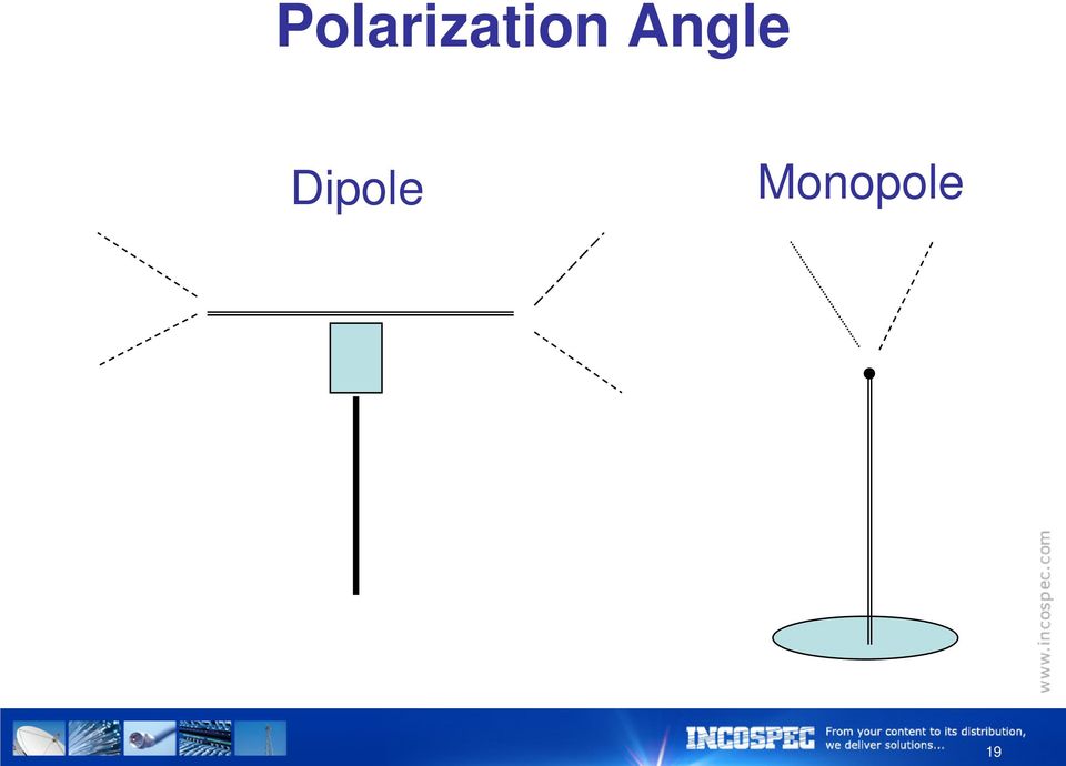
16 FCC/IC Regulations & Procedures for Leakage Measurement < 54 MHz & > 216 MHz = 30m > 54 MHz & < 216 MHz = 3m Use a calibrated half-wave dipole antenna Antenna must be elevated 3 meters off the ground and positioned 3 meters from the leakage source 16

17 Patrolling for Leakage 20µVm 3 meters 30 meters 2 µvm 17

18 µv/m Standard unit of measure for Leakage 50 Ohm off air measurement Voltage developed in 1 meter of infinitely thin section of wire submerged in a leakage field, produces 1µV of energy 18

19 Polarization Angle Dipole Monopole 19
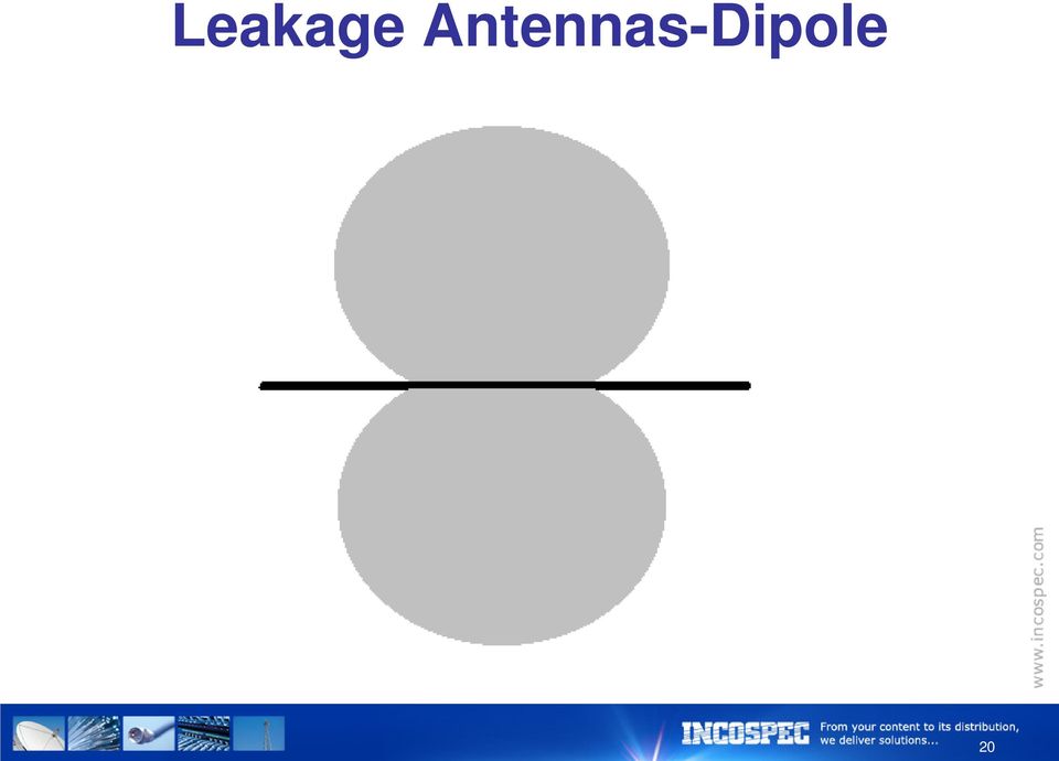
20 Leakage Antennas-Dipole 20
21 Cumulative Leakage Index (CLI) CLI is the net effect of the combination of all the leaks in the system added together These cumulative leaks form an invisible cloud of unwanted RF energy over the cable system 21
22 Required Actions All leaks 20 µv/m must be logged and fixed Only leaks above 50 µv/m are used in CLI calculation All measurements taken outside MHz must be converted as if they were taken within the band 22
23 Reason #3 to Monitor for Leakage Improves System Performance Reduces Repeat Service Calls Locate Physical Problems 23
24 Common Causes 70% of all leakage is caused by problems between the tap and entry to the house Aging and environmental stress Physical trauma to cables or connectors Loose drop connectors Inferior quality coaxial cable, passives, or connectors Loose hard line connectors 24
25 Other Causes of Leakage Improperly installed connectors Cracks in the distribution and feeder cable Animal chews Poorly-shielded drop cable Bad connectors at the tap Bad/loose port terminators Corroded connectors 25
26 Other Causes (Cont d) Customer installed equipment Damaged amplifier housing or loose lids Loose tap plates Broken tap ports Poor installation of splices and connectors Poorly-shielded customer premise gear 26
27 Tools Dipole Monopole 27
28 Signal Phasing 28
29 Standing Waves 29
30 Electrical Noise 30
31 Characterizing Signal Leakage from an All-Digital Cable Network Ron Hranac and Ray Thomas (Comcast) have conducted field tests on the subject a couple of years ago SCTE live Learning presentation on the subject erence/recordingdefault.aspx?c_psrid=e D50D
32 Characterizing Signal Leakage from an All-Digital Cable Network Field tests were conducted in the Denver, Co area using an analog CW carrier and a 256 QAM carrier CW test frequency was Ch. MHz Digital test with 256QAM 147Mhz Digital test with power -6dBc from CW (video) Testing leakage carrier in between 2 QAMs Minimum spectrum protection for CW vs QAM 32
33 Characterizing Signal Leakage from an All-Digital Cable Network Review the characteristics of the analog and digital carriers Review type of modulation Where the RF energy is located Historical test instruments to measure leakage Troubleshooting gear MER/BER performance behavior being deteriorated by signal ingress 33
34 Typical Analog & Digital Carriers 34
35 Analog Video Carrier 35
36 Analog A/V Carriers MHz Video Carrier -10 Audio Carrier Amplitude Modulation db Sous-porteuse couleur 4.2 MHz FM Modulation +/- 25 KHz MHz MHz MHz 4.5 MHz 36
37 Analog C/I Objective Table MHz Red designates Visible interference Green designates Non-visible interference db MHz 4.5 MHz 37
38 Analog Carrier with Modulation 38
39 Typical Digital QAM Carriers 39
40 Characterizing Signal Leakage from an All-Digital Cable Network Conclusion from Hranac/Comcast test results: Leaks from digital QAM carriers can cause harmful interference to terrestrial users just like analog carriers Terrestrial RF energy can impair on QAM signals depending on the level of the ingress Patrol leakage program should apply to alldigital systems The compliance spec for all-digital networks is similar as for analog cable systems 40
41 Characterizing Signal Leakage from an All-Digital Cable Network Summary and conclusion of SCTE tests (cont d): A CW carrier is still the most cost/efficient method for testing and troubleshooting leakage The minimum frequency offset allocation to a QAM is 1 MHz The frequency range for leakage detectors can be from 108MHz ~147MHz (Aeronautical band) Allocating CW carrier between 2 QAM carriers will impair on both QAM carriers Video carrier from analog modulator may be used 41
42 Characterizing Signal Leakage from an All-Digital Cable Network Summary and conclusion of SCTE tests (cont d): Some manufacturers are working on or already supplying leakage detection tools for digital QAM carriers Cost efficiency of digital leakage instrumentation will accelerate its deployment in all-digital cable systems 42
43 Leakage Downstream Ingress Facts Being leakage compliant with rules and regulations increases the figure of merit of the HFC network Higher MER levels throughout the RF plant - greater signals reliability The average MER objective at the subscriber tap of 33dB ~ 35dB 43
44 MER TARGET - THE CLIFF EFFECT P Operating margin Zone Risk Zone RS-FEC Crash Zone Upstream 16 QAM >22dB 22dB - 20dB <17dB Objective UP/Downstream 64 QAM >28dB 28dB - 26dB <23dB P- BER CER Downstream 256 QAM >33dB 33dB - 31dB <28dB 1 x x
45 Constellation Performance Good MER Bad MER 45
46 QAM EVS Troubleshooting in-channel ingress is easy with QAM EVS mode Typical ingress areas Loose connector Broken shields Tap plate loose Home wiring CSO/CTB from house amp Sweep inter-mod 46
47 Digital signals work well until very close to the point of failure Measurement of digital carriers is critical in determining the system margin BER Signal level MER Pre/Post BER CER (Codedword Error Rate) The BER helps to find problems related to point of failure. Gray lines designate marginal signal quality Black lines is a sign of macro-blocks and picture pixelling 47
48 BER/CER BER Pre: before FEC repair Post: after FEC repair ERRORS Corr = corrected codewords uncor = uncorrectable codewords err sec = errored seconds sev sec = severely errored seconds Codeword Error Rate: Objective = 9x10 ⁷ 48
49 MER/BER Demonstration Impairment simulation affected by leakage 49
50 Characterizing Signal Leakage from an All-Digital Cable Network Thank you, Gracias, Danki, Merci to the CCTA members Mario Sebastiani: Serving the industry since 1978 with pride, integrity and commitment 50
51 Tools Dipole Monopole 51
52 Some of Incospec s Associates 52
Technical Training Seminar on Practical Field Testing DOCSIS 3.0 for CCTA Member Companies August 24, 25 and 26, 2010 San Juan, Puerto Rico
 Technical Training Seminar on Practical Field Testing DOCSIS 3.0 for CCTA Member Companies August 24, 25 and 26, 2010 San Juan, Puerto Rico Mario Sebastiani Tony Holmes Overview Quick discussion of DOCSIS
Technical Training Seminar on Troubleshooting the Triple Play Services for CCTA Member Companies August 24, 25, 26, 2010 San Juan, Puerto Rico
 Technical Training Seminar on Troubleshooting the Triple Play Services for CCTA Member Companies August 24, 25, 26, 2010 San Juan, Puerto Rico Mario Sebastiani Tony Holmes Seminar Overview Digital Troubleshooting
Broadband 101: Installation and Testing
 Broadband 101: Installation and Testing Fanny Mlinarsky Introduction Today the Internet is an information superhighway with bottlenecks at every exit. These congested exits call for the deployment of broadband
CX380X Advanced Spectrum and Burst QAM Analyzer
 Advanced Spectrum and Burst QAM Analyzer Preventative Network Monitoring With VeEX s VeSion system, the s advanced Spectrum Analyzer and Bursty Demodulator captures rogue cable modems and provides proactive
Digital Signals and Testing
 Digital Signals and Testing My Business Card Jerry Green Regional Sales/Support Engineer 707-694-9672 Phone 800-297-9726 tech support [email protected] www.sunrisetelecom.com/broadband Agenda and
Cable 101. A Broadband Telecommunications Primer for Non-technical Personnel
 Cable 101 KnowledgeLink, Inc. A Broadband Telecommunications Primer for Non-technical Personnel Presented by: Justin J. Junkus President, KnowledgeLink, Inc. November 20, 2013 Agenda Broadband Cable Systems
Channel Bandwidth, MHz. Symbol Rate, Msym/sec
 APPENDIXB Information in the following tables is from the DOCSIS and EuroDOCSIS Radio Frequency Interface Specification, and should be considered minimum recommended performance criteria for reliable data
R&S EFL110/ R&S EFL210 Cable TV Analyzer and Leakage Detector Detecting interference in cable TV and LTE networks
 R&S EFL110/ R&S EFL210 Cable TV Analyzer and Leakage Detector Detecting interference in cable TV and LTE networks Broadcasting Product Brochure 01.00 R&S EFL110/ R&S EFL210 Cable TV Analyzer and Leakage
Proactive Network Maintenance for EPoC
 Proactive Network Maintenance for EPoC Contributors: Bruce Currivan, Richard Prodan, Thomas Kolze, Hesham ElBakoury, Bernard Arambepola, Belal Hamzeh, Mark Laubach www.broadcom.com SUMMARY Cable operators
COMPATIBILITY AND SHARING ANALYSIS BETWEEN DVB T AND RADIO MICROPHONES IN BANDS IV AND V
 European Radiocommunications Committee (ERC) within the European Conference of Postal and Telecommunications Administrations (CEPT) COMPATIBILITY AND SHARING ANALYSIS BETWEEN DVB T AND RADIO MICROPHONES
: Coaxial Cable Television Interference to Aviation Systems EXECUTIVE SUMMARY
 EUROCONTROL DIS/COM/SD Date : 15.03.2001 Subject Origin : Coaxial Cable Television Interference to Aviation Systems : EUROCONTROL EXECUTIVE SUMMARY This paper provides a brief on the impact of cable television
DSAM Digital Quality Index (DQI) A New Technique for Assessing Downstream Digital Services
 A New Technique for Assessing Downstream Digital Services") Application Note DSAM Digital Quality Index (DQI) A New Technique for Assessing Downstream Digital Services Overview As cable operators move to digital simulcast and all digital networks, the majority
Application Note DSAM Digital Quality Index (DQI) A New Technique for Assessing Downstream Digital Services Overview As cable operators move to digital simulcast and all digital networks, the majority
DT3: RF On/Off Remote Control Technology. Rodney Singleton Joe Larsen Luis Garcia Rafael Ocampo Mike Moulton Eric Hatch
 DT3: RF On/Off Remote Control Technology Rodney Singleton Joe Larsen Luis Garcia Rafael Ocampo Mike Moulton Eric Hatch Agenda Radio Frequency Overview Frequency Selection Signals Methods Modulation Methods
for the Operation of Digital Cable Television Systems
 Technical Conditions Technical Conditions for the Operation of Digital Cable Television Systems Document No: ComReg 98/66R Date: December, 2002 An Coimisiún um Rialáil Cumarsáide Commission for Communications
VSE-1100. The all-new digital spectrum/video analyzer and noise troubleshooter
 The all-new digital spectrum/video analyzer and noise troubleshooter The VSE-1100 helps cable service providers maintain optimal network performance in the modern digital cable environment. Enabling fast
Broadband Technology Clinic. Burlington Telecom Advisory Board
 Broadband Technology Clinic Burlington Telecom Advisory Board 1 What are the Defining Characteristics of a Broadband Service? Speed - Throughput capability both down and upstream Performance - Latency
Technical Standards and Requirements for Radio Apparatus Capable of Receiving Television Broadcasting
 Issue 2 June 2008 Spectrum Management and Telecommunications Broadcasting Equipment Technical Standard Technical Standards and Requirements for Radio Apparatus Capable of Receiving Television Broadcasting
FCC CABLE RULES. 76.605 Technical Standards
 CODE OF FEDERAL REGULATIONS TITLE 47 -- TELECOMMUNICATION CHAPTER I -- FEDERAL COMMUNICATIONS COMMISSION SUBCHAPTER C -- BROADCAST RADIO SERVICES PART 76--CABLE TELEVISION SERVICE 76.605 Technical Standards
MSB MODULATION DOUBLES CABLE TV CAPACITY Harold R. Walker and Bohdan Stryzak Pegasus Data Systems ( 5/12/06) [email protected]
 pegasusdat@aol.com") MSB MODULATION DOUBLES CABLE TV CAPACITY Harold R. Walker and Bohdan Stryzak Pegasus Data Systems ( 5/12/06) [email protected] Abstract: Ultra Narrow Band Modulation ( Minimum Sideband Modulation ) makes
MSB MODULATION DOUBLES CABLE TV CAPACITY Harold R. Walker and Bohdan Stryzak Pegasus Data Systems ( 5/12/06) [email protected] Abstract: Ultra Narrow Band Modulation ( Minimum Sideband Modulation ) makes
Study of RF Spectrum Emissions in High Pressure Sodium and Metal Halide Lamps. Lawrence P. Glaister VE7IT, Automation Engineer.
 Study of RF Spectrum Emissions in High Pressure Sodium and Metal Halide Lamps Lawrence P. Glaister VE7IT, Automation Engineer May 2010 Abstract: This research was performed in collaboration with the City
Broadband over Power Line (BPL) Test Procedures and Equipment Authorization
 Test Procedures and Equipment Authorization") Broadband over Power Line (BPL) Test Procedures and Equipment Authorization Andy Leimer Equipment Authorization Branch Federal Communications Commission Office of Engineering and Technology Laboratory
Broadband over Power Line (BPL) Test Procedures and Equipment Authorization Andy Leimer Equipment Authorization Branch Federal Communications Commission Office of Engineering and Technology Laboratory
1550 Video Overlay for FTTH
 1550 Video Overlay for FTTH The New Old Reliable Fernando Villarruel Leonard Ray John McKeon Service Provider Video Technology Group 1 Presentation Overview Background of Overlay in PON Deployment Architecture
Deviser DS2800 Handheld Digital TV Spectrum Analyser
 Deviser DS2800 Handheld Digital TV Spectrum Analyser Cost-Effective Tough & Durable Easy to Use Long Battery Life The Deviser DS2800 Series Spectrum Analyser is packed full of new technologies designed
IsumaTV. Media Player Setup Manual COOP Cable System. Media Player
 IsumaTV Media Player Setup Manual COOP Cable System Visual Setup Front: Router Scan Converter Media Player Video Modulator Equipment: Media Player: Router: Scan Converter: Video Modulator: This computer
AN1200.04. Application Note: FCC Regulations for ISM Band Devices: 902-928 MHz. FCC Regulations for ISM Band Devices: 902-928 MHz
 AN1200.04 Application Note: FCC Regulations for ISM Band Devices: Copyright Semtech 2006 1 of 15 www.semtech.com 1 Table of Contents 1 Table of Contents...2 1.1 Index of Figures...2 1.2 Index of Tables...2
Digital Active Indoor Antenna SRT ANT 10 ECO
 Digital Active Indoor Antenna SRT ANT 10 ECO Picture similar User Manual Table of contents 1.0 INTRODUCTION 1 2.0 PACKAGE CONTENT 1 3.0 SAFETY NOTES 2 4.0 CONNECTING THE ANTENNA 2 1.0 INTRODUCTION Thank
DS2800. Broadband. Spectrum Analyzer. Key Benefits CUSTOMER PREMISE HFC DS2800. www.deviserinstruments.com
 Broadband DS2800 Spectrum Analyzer Key Benefits An all-in-one tool for installation, verification and maintenance of cable networks Ensure proper installation on the first visit reducing service calls
INTRODUCTION FIGURE 1 1. Cosmic Rays. Gamma Rays. X-Rays. Ultraviolet Violet Blue Green Yellow Orange Red Infrared. Ultraviolet.
 INTRODUCTION Fibre optics behave quite different to metal cables. The concept of information transmission is the same though. We need to take a "carrier" signal, identify a signal parameter we can modulate,
MATRIX TECHNICAL NOTES
 200 WOOD AVENUE, MIDDLESEX, NJ 08846 PHONE (732) 469-9510 FAX (732) 469-0418 MATRIX TECHNICAL NOTES MTN-107 TEST SETUP FOR THE MEASUREMENT OF X-MOD, CTB, AND CSO USING A MEAN SQUARE CIRCUIT AS A DETECTOR
ACRS 2.0 User Manual 1
 ACRS 2.0 User Manual 1 FCC Regulatory Information This device complies with part 15 of the FCC Rules. Operation is subject to the following two conditions: (1) This device may not cause harmful interference,
E-Option Multi-taps Conditioning at the Tap
 E-Option Multi-taps Conditioning at the Tap (actual size) Introduction Traditional Cable Television Systems had long been associated with one-way downstream signal transmissions that provide video services
MyM 3T. User Manual. English
 User Manual Compact unit with 2 DVB-T tuners MPEG-2 and MPEG-4 compliant 3 analogue modulators Two CI for decryption or multidecryption NICAM or A2 stereo 12-volt power supply Low power consumption MyM
Embedded FM/TV Antenna System
 1 Embedded FM/TV Antenna System Final Report Prepared for By January 21, 2011 2 Table of Contents 1 Introduction... 5 2 Technical Specification... 6 3 Prototype Antenna... 7 4 FASTROAD Active module fabrication...
INTRODUCTION TO COMMUNICATION SYSTEMS AND TRANSMISSION MEDIA
 COMM.ENG INTRODUCTION TO COMMUNICATION SYSTEMS AND TRANSMISSION MEDIA 9/6/2014 LECTURES 1 Objectives To give a background on Communication system components and channels (media) A distinction between analogue
Network Requirements for DSL systems, (ADSL through G.Fast) (A summarized view)
 (A summarized view)") Network Requirements for DSL systems, (ADSL through G.Fast) (A summarized view) Gilberto GG Guitarte, BB Connectivity Director TE Connectivity FTTH LATAM Chapter CHAIRMAN 2/24/2014 G.A.Guitarte 1 Executive
Network Requirements for DSL systems, (ADSL through G.Fast) (A summarized view) Gilberto GG Guitarte, BB Connectivity Director TE Connectivity FTTH LATAM Chapter CHAIRMAN 2/24/2014 G.A.Guitarte 1 Executive
Jeff Thomas Tom Holmes Terri Hightower. Learn RF Spectrum Analysis Basics
 Jeff Thomas Tom Holmes Terri Hightower Learn RF Spectrum Analysis Basics Learning Objectives Name the major measurement strengths of a swept-tuned spectrum analyzer Explain the importance of frequency
ELEMENTS OF CABLE TELEVISION
 1 ELEMENTS OF CABLE TELEVISION Introduction Cable television, from its inception, developed in western countries into two separate systems called Master Antenna Television (MATV) and Community Cable Television
Cable Network Overview. Presented by: Ma1 Schmi1 (CableLabs)
") Cable Network Overview Presented by: Ma1 Schmi1 (CableLabs) Contributors & Supporters Alphabe?cal by First Name Alberto Campos, CableLabs Edwin Malle1e, Bright House Networks Eugene Dai, Cox Communica?ons
Cable Network Overview Presented by: Ma1 Schmi1 (CableLabs) Contributors & Supporters Alphabe?cal by First Name Alberto Campos, CableLabs Edwin Malle1e, Bright House Networks Eugene Dai, Cox Communica?ons
Transition from Analog to High Definition Television in Hospitals
 Transition from Analog to High Definition Television in Hospitals Presentation Outline Introduction Why the Transition? What is Digital TV & High Definition? Roadmap Video Content Signal Source Cable Distribution
Next Generation of High Speed. Modems8
 Next Generation of High Speed Modems High Speed Modems. 1 Traditional Modems Assume both ends have Analog connection Analog signals are converted to Digital and back again. Limits transmission speed to
Digital Satellite Receiver
 USER GUIDE Digital Satellite Receiver Models DSR207, DSR317, DSR505, and DSR530 CONTENTS IMPORTANT SAFETY INSTRUCTIONS...1 DSR BASICS SYMBOLS/ICONS...6 Front Panel...6 Back Panel...7 CONNECTING YOUR DSR...10
Technicolor ATSC-8. User s Guide. 2012 Technicolor. All Rights reserved
 Technicolor ATSC-8 User s Guide 2012 Technicolor. All Rights reserved Introduction This document describes the process and procedures for integrating the ATSC-8 product with the COM1000 digital head-end
ETSI EN 302 774 V1.2.1 (2012-02)
") EN 302 774 V1.2.1 (2012-02) Harmonized European Standard Broadband Wireless Access Systems (BWA) in the 3 400 MHz to 3 800 MHz frequency band; Base Stations; Harmonized EN covering the essential requirements
EN 302 774 V1.2.1 (2012-02) Harmonized European Standard Broadband Wireless Access Systems (BWA) in the 3 400 MHz to 3 800 MHz frequency band; Base Stations; Harmonized EN covering the essential requirements
Dynatel Advanced Modular System 965AMS 30-Megahertz Spectrum Analyzer
 3 Dynatel Advanced Modular System 965AMS 30-Megahertz Spectrum Analyzer DSL User s Guide Future-Proof Testing Platform February 2009 78-8140-2658-5-A 2 3M Dynatel Advanced Modular System 965AMS 30-MHz
DSAM Digital Services Activation Meter
 DSAM Digital Services Activation Meter Designed for your business All-in-one tester incorporating state-of-the-art DSP and DOCSIS technologies to test cable modem service, digital video, analog video and
FCC PART 15B CLASS A MEASUREMENT AND TEST REPORT
 FCC PART 15B CLASS A MEASUREMENT AND TEST REPORT For SAMBO HI TECH CO., LTD. 616-15, GANSUK4-DONG, NAMDONG-GU, INCHUN 405-810, KOREA Model: LSR700, SCI545HV1EF, SCI545HVEF This Report Concerns: Original
EMC STANDARDS STANDARDS AND STANDARD MAKING BODIES. International. International Electrotechnical Commission (IEC) http://www.iec.
 http://www.iec.") EMC STANDARDS The EMC standards that a particular electronic product must meet depend on the product application (commercial or military) and the country in which the product is to be used. These EMC regulatory
EMC STANDARDS The EMC standards that a particular electronic product must meet depend on the product application (commercial or military) and the country in which the product is to be used. These EMC regulatory
Data Transmission. Data Communications Model. CSE 3461 / 5461: Computer Networking & Internet Technologies. Presentation B
 CSE 3461 / 5461: Computer Networking & Internet Technologies Data Transmission Presentation B Kannan Srinivasan 08/30/2012 Data Communications Model Figure 1.2 Studying Assignment: 3.1-3.4, 4.1 Presentation
Introduction to RF Engineering. Andrew CLEGG
 Introduction to RF Engineering Andrew CLEGG 1 Comparing the Lingo Radio Astronomers Speak a Unique Vernacular We are receiving interference from your transmitter at a level of 10 janskys What the ^#$&
Network Analyzer Operation
 Network Analyzer Operation 2004 ITTC Summer Lecture Series John Paden Purposes of a Network Analyzer Network analyzers are not about computer networks! Purposes of a Network Analyzer Measures S-parameters
Cable Television System Measurements Handbook. NTSC Systems February 1994
 Cable Television System Measurements Handbook NTSC Systems February 1994 H Cable Television System Measurements Handbook NTSC Systems February 1994 Copyright Hewlett-Packard Company 1994 1400 Fountain
TECHNICAL INFORMATION FOR FREQUENCY PLANNING IN-BUILDING COAXIAL CABLE DISTRIBUTION SYSTEM (IBCCDS)
") HKTA 1105 ISSUE 5 TECHNICAL INFORMATION FOR FREQUENCY PLANNING OF IN-BUILDING COAXIAL CABLE DISTRIBUTION SYSTEM (IBCCDS) TELECOMMUNICATIONS AUTHORITY HONG KONG FOREWORD 1. This document intends to provide
HKTA 1105 ISSUE 5 TECHNICAL INFORMATION FOR FREQUENCY PLANNING OF IN-BUILDING COAXIAL CABLE DISTRIBUTION SYSTEM (IBCCDS) TELECOMMUNICATIONS AUTHORITY HONG KONG FOREWORD 1. This document intends to provide
MoCA 1.1 Specification for Device RF Characteristics
 MoCA 1.1 Specification for Device RF Characteristics 20140211 Copyright 2012, 2014 Multimedia Over Coax Alliance. All Rights Reserved. MoCA is a trademark or registered trademark of the Multimedia Over
The front end of the receiver performs the frequency translation, channel selection and amplification of the signal.
 Many receivers must be capable of handling a very wide range of signal powers at the input while still producing the correct output. This must be done in the presence of noise and interference which occasionally
FREQUENCY RESPONSE ANALYZERS
 FREQUENCY RESPONSE ANALYZERS Dynamic Response Analyzers Servo analyzers When you need to stabilize feedback loops to measure hardware characteristics to measure system response BAFCO, INC. 717 Mearns Road
Why is Passive Intermodulation Important?
 Precision Products for Demanding Applications Low PIM Products for Distributed Antenna Systems and Wireless Infrastructure Low PIM Coaxial Cable Assemblies Plenum Rated, Low PIM, Low Loss Coaxial Cable
RFS-805. Digital Modulator AV to COFDM. User Manual
 RFS-805 Digital Modulator AV to COFDM User Manual 1. Purpose of use RFS-805 is a digital modulator designed for a processing audio and video signals into COFDM (DVB-T) multiplex. 2. Installation The connections
Technical Review of the Comcast Cable System Serving Seattle, Washington
 Technical Review of the Comcast Cable System Serving Seattle, Washington By Dick Nielsen Senior Engineer CBG Communications, Inc. May, 2009 Introduction and Background 1 Findings 2 System Design Characteristics
RX-AM4SF Receiver. Pin-out. Connections
 RX-AM4SF Receiver The super-heterodyne receiver RX-AM4SF can provide a RSSI output indicating the amplitude of the received signal: this output can be used to create a field-strength meter capable to indicate
Applications in EMC testing. Outline. Antennas for EMC Testing. Terminology
 Antennas for EMC Testing Zhong Chen ETS-Lindgren 1301 Arrow Point Drive Cedar Park, TX 78613 [email protected] Outline EMC Terms and Definitions Typical EMC Antennas Calibration of EMC Antennas
Jeff Thomas Tom Holmes Terri Hightower. Learn RF Spectrum Analysis Basics
 Jeff Thomas Tom Holmes Terri Hightower Learn RF Spectrum Analysis Basics Agenda Overview: Spectrum analysis and its measurements Theory of Operation: Spectrum analyzer hardware Frequency Specifications
Siemens Energy & Automation. structured. WIRING Product Training Series: Advanced Video Session 3
 s structured WIRING Product Training Series: Advanced Video Session 3 1 Table of Contents This presentation will give you a closer look at Video in Structured Wiring applications. The following Areas will
Troubleshooting accelerometer installations
 Troubleshooting accelerometer installations Accelerometer based monitoring systems can be tested to verify proper installation and operation. Testing ensures data integrity and can identify most problems.
Telephony Solution for Local Multi-Point Distribution Service
 Telephony Solution for Local Multi-Point Distribution Service Derek Lam Computer Systems Laboratory Aly F. Elrefaie, Lynn Plouse, Yee-Hsiang Chang Video Communications Division HPL-97-165 December, 1997
Application Note: Spread Spectrum Oscillators Reduce EMI for High Speed Digital Systems
 Application Note: Spread Spectrum Oscillators Reduce EMI for High Speed Digital Systems Introduction to Electro-magnetic Interference Design engineers seek to minimize harmful interference between components,
Implementing Digital Wireless Systems. And an FCC update
 Implementing Digital Wireless Systems And an FCC update Spectrum Repacking Here We Go Again: The FCC is reallocating 600 MHz Frequencies for Wireless Mics 30-45 MHz (8-m HF) 174-250 MHz (VHF) 450-960 MHz
Chapter 9 Using Telephone and Cable Networks for Data Transmission
 9-11 TELEPHONE NETWORK Chapter 9 Using Telephone and Cable Networks for Data Transmission 1 McGraw-Hill Copyright The McGraw-Hill Companies, Inc. Permission required The for reproduction McGraw-Hill or
Amplifier for Small Magnetic and Electric Wideband Receiving Antennas (model AAA-1B)
") Amplifier for Small Magnetic and Electric Wideband Receiving Antennas (model AAA-1B) 1. Description and Specifications Contents 1.1 Description 1.2 1.2 Specifications 1.3 1.3 Tested parameters in production
Amplifier for Small Magnetic and Electric Wideband Receiving Antennas (model AAA-1B) 1. Description and Specifications Contents 1.1 Description 1.2 1.2 Specifications 1.3 1.3 Tested parameters in production
Broadband Video over Twisted Pair Cabling. By Paul Kish Director, IBDN Systems & Standards NORDX/CDT
 Broadband Video over Twisted Pair Cabling By Paul Kish Director, IBDN Systems & Standards NORDX/CDT December 2002 Introduction Over the last 10 years we have seen some tremendous advances in the manufacturing
MODULATION Systems (part 1)
") Technologies and Services on Digital Broadcasting (8) MODULATION Systems (part ) "Technologies and Services of Digital Broadcasting" (in Japanese, ISBN4-339-62-2) is published by CORONA publishing co.,
Technologies and Services on Digital Broadcasting (8) MODULATION Systems (part ) "Technologies and Services of Digital Broadcasting" (in Japanese, ISBN4-339-62-2) is published by CORONA publishing co.,
MANAGEMENT OF BI-DIRECTIONAL AMPLIFIERS IN THE LAND MOBILE SERVICE IN THE FREQUENCY RANGE 29.7 MHz TO 520 MHz
 RALI : LM 6 DATE OF EFFECT :.13/03/96 Sequence Number :.66 Radiocommunications Assignment and Licensing Instruction MANAGEMENT OF BI-DIRECTIONAL AMPLIFIERS IN THE LAND MOBILE SERVICE IN THE FREQUENCY RANGE
MYRICOM, INC. TEST REPORT FOR THE SERVER RACK, 10G-PCIE2-8B2-2S & 10G-PCIE2-8B2-2QP FCC PART 15 SUBPART B SECTIONS 15.107 AND 15.109 CLASS A TESTING
 TESTING CERT #803.01, 803.02, 803.05, 803.06 MYRICOM, INC. TEST REPORT FOR THE SERVER RACK, 10G-PCIE2-8B2-2S & 10G-PCIE2-8B2-2QP FCC PART 15 SUBPART B SECTIONS 15.107 AND 15.109 CLASS A TESTING DATE OF
CATV Balun II (500302)
") CATV Balun II (500302) Application Guide Version 1.05 Oct 2010 MuxLab Inc. 2007-2010 1 Introduction Broadband CATV has experienced a steady growth in recent years due to the introduction of digital cable
CATV Balun II (500302) Application Guide Version 1.05 Oct 2010 MuxLab Inc. 2007-2010 1 Introduction Broadband CATV has experienced a steady growth in recent years due to the introduction of digital cable
Cisco Cable Radio Frequency (RF) FAQs
 FAQs") Table of Contents Cable Radio Frequency (RF) FAQs...1 Questions...1...1 Related Information...8 i Cable Radio Frequency (RF) FAQs Questions How do I measure the upstream RF signal? How do I measure the
Table of Contents Cable Radio Frequency (RF) FAQs...1 Questions...1...1 Related Information...8 i Cable Radio Frequency (RF) FAQs Questions How do I measure the upstream RF signal? How do I measure the
DOCSIS 3.1: WHAT IS IT, HOW DOES IT WORK, AND HOW CAN YOU PREPARE FOR IT? Daniel Howard, SCTE CTO July 16, 2013
 DOCSIS 3.1: WHAT IS IT, HOW DOES IT WORK, AND HOW CAN YOU PREPARE FOR IT? Daniel Howard, SCTE CTO July 16, 2013 VIDEO PART 1: OFDM BUSINESS DRIVERS MAIN OBJECTIVES: As we go through Part 1 of today s lecture,
Agilent AN 1316 Optimizing Spectrum Analyzer Amplitude Accuracy
 Agilent AN 1316 Optimizing Spectrum Analyzer Amplitude Accuracy Application Note RF & Microwave Spectrum Analyzers Table of Contents 3 3 4 4 5 7 8 8 13 13 14 16 16 Introduction Absolute versus relative
CE Test Report. : Microchip Technology Inc. 2355 West Chandler Blvd., Chandler, Arizona 85224-6199, USA
 CE Test Report Equipment : IEEE 802.11b/g Wireless LAN module Brand Name : MICROCHIP Model No. : MRF24WG0MA/MB Standard : EN 300 328 V1.8.1 (2012-06) Operating Band : 2400 MHz 2483.5 MHz Applicant Manufacturer
AC3200 INTELLIGENT BROADBAND AMPLIFIER
 Kari Mäki 9.4.2013 1(7) AC3200 INTELLIGENT BROADBAND AMPLIFIER AC3200 is the latest leading-edge addition to AC family with extended frequency and gain ranges and integrated electrical controls in both
TV & SATELLITE LEVEL METERS
 PROLINK A BIG FAMILY The PROLINK series of PROMAX Signal Level Meters are an ideal solution for those companies that need multifunctional equipment for installation, certification and maintenance purposes
Lynx Broadband Installation Manual for Residential Packages with a 20 db Amp Quick Start Guide (first two pages)
") Lynx Broadband Installation Manual for Residential Packages with a 20 db Amp Quick Start Guide (first two pages) 1. Be sure that your kit includes all the parts shown in the Check the Equipment section
Lynx Broadband Installation Manual for Residential Packages with a 20 db Amp Quick Start Guide (first two pages) 1. Be sure that your kit includes all the parts shown in the Check the Equipment section
MoCA Testing for triple play and Whole Home DVR. Jim Carvajal Applications Specialist, Cable MSO Caribbean & Latin America
 MoCA Testing for triple play and Whole Home DVR Jim Carvajal Applications Specialist, Cable MSO Caribbean & Latin America Agenda What is MoCA? Home Troubleshooting JDSU troubleshooting SmartID 2012 JDS
UNDERSTANDING THE FCC REGULATIONS FOR LOW-POWER, NON-LICENSED TRANSMITTERS
 Office of Engineering and Technology Federal Communications Commission UNDERSTANDING THE FCC REGULATIONS FOR LOW-POWER, NON-LICENSED TRANSMITTERS OET BULLETIN NO. 63 October 1993 (Supersedes September
Digital Signal Measurement Guidelines
 guidlns.fm Page 1 Thursday, December 10, 1998 2:33 PM 1 Digital Signal Measurement Guidelines This chapter introduces guidelines to help you understand digital signals in an analog world. What you will
Operation Manual for Users
 Operation Manual for Users Model No.: FLTAMFMRCD!!!!!!!!!! ATTENTION!!!!!!!!!! THE RESET BUTTON MUST BE PRESSED TO ENSURE PROPER OPERATION. SEE INSTRUCTION MANUAL Table of Contents Table of Contents ---------------------------------------------------------------------------------------------
How To Define Hfc Technology
 Cable network topologies and implications for evolutionary approaches 33 rd International conference and Exhibition PIKE 2008, Zakopane, 14 October 2008 Bart Brusse, ReDeSign Project Manager Pressure on
DDX 7000 & 8003. Digital Partial Discharge Detectors FEATURES APPLICATIONS
 DDX 7000 & 8003 Digital Partial Discharge Detectors The HAEFELY HIPOTRONICS DDX Digital Partial Discharge Detector offers the high accuracy and flexibility of digital technology, plus the real-time display
Model GS7000 4-Port Node 1 GHz with 40/52 MHz split
 Model GS7000 4-Port Node 1 GHz with 40/52 MHz split The Model GS7000 4-Port Node is our latest generation 1 GHz optical node platform and utilizes a completely new housing designed for optimal heat dissipation.
SPECTRUM MONITOR MC-277B
 SPECTRUM MONITOR 1 GENERAL INFORMATION 1.1 Description The field level meter is designed to take the required measurements in a collective antenna and/or satellite system. It covers the television, hyperband
This high-performance TV signal analyzer provides analog/digital TV and satellite TV monitoring and provides various video decoding.
 This high-performance TV signal analyzer provides analog/digital TV and satellite TV monitoring and provides various video decoding. Overview This high-performance TV signal analyzer features DVB-C/S/S2
Achieving New Levels of Channel Density in Downstream Cable Transmitter Systems: RF DACs Deliver Smaller Size and Lower Power Consumption
 Achieving New Levels of Channel Density in Downstream Cable Transmitter Systems: RF DACs Deliver Smaller Size and Lower Power Consumption Introduction By: Analog Devices, Inc. (ADI) Daniel E. Fague, Applications
Tuning a Monopole Antenna Using a Network Analyzer
 11/21/11 Tuning a Monopole Antenna Using a Network Analyzer Chris Leonard Executive Summary: When designing a monopole antenna it is important to know at which frequency the antenna will be operating at.
Delaware Valley SCTE Comparing RF-over-Glass to HFC. Bill Dawson VP Business Development ARRIS Access & Transport bill.dawson@arrisi.
 Delaware Valley SCTE Comparing RF-over-Glass to HFC Bill Dawson VP Business Development ARRIS Access & Transport [email protected] December 8, 2010 Agenda RFoG basics - what is RFoG? Why choose RFoG?
Preview of Period 3: Electromagnetic Waves Radiant Energy II
 Preview of Period 3: Electromagnetic Waves Radiant Energy II 3.1 Radiant Energy from the Sun How is light reflected and transmitted? What is polarized light? 3.2 Energy Transfer with Radiant Energy How
1. (Ungraded) A noiseless 2-kHz channel is sampled every 5 ms. What is the maximum data rate?
 A noiseless 2-kHz channel is sampled every 5 ms. What is the maximum data rate?") Homework 2 Solution Guidelines CSC 401, Fall, 2011 1. (Ungraded) A noiseless 2-kHz channel is sampled every 5 ms. What is the maximum data rate? 1. In this problem, the channel being sampled gives us the
Homework 2 Solution Guidelines CSC 401, Fall, 2011 1. (Ungraded) A noiseless 2-kHz channel is sampled every 5 ms. What is the maximum data rate? 1. In this problem, the channel being sampled gives us the
How To Make A Network More Interactive
 CaLan 3010/2010 Test Equipment Install, Maintain and Troubleshoot Your Interactive Broadband Cable Networks Improve Field Productivity and Increase Customer Satisfaction with Flexible, Integrated Agilent
LVDS Technology Solves Typical EMI Problems Associated with Cell Phone Cameras and Displays
 AN-5059 Fairchild Semiconductor Application Note May 2005 Revised May 2005 LVDS Technology Solves Typical EMI Problems Associated with Cell Phone Cameras and Displays Differential technologies such as
Selecting Receiving Antennas for Radio Tracking
 Selecting Receiving Antennas for Radio Tracking Larry B Kuechle, Advanced Telemetry Systems, Inc. Isanti, Minnesota 55040 [email protected] The receiving antenna is an integral part of any radio location
DDX 7000 & 8003. Digital Partial Discharge Detectors FEATURES APPLICATIONS
 DDX 7000 & 8003 Digital Partial Discharge Detectors The HAEFELY HIPOTRONICS DDX Digital Partial Discharge Detector offers the high accuracy and flexibility of digital technology, plus the real-time display