Quick Design & Install Guide. Computerised Emergency Evacuation System LONWORKS TM Powerline Technology
|
|
|
- Claribel Waters
- 10 years ago
- Views:
Transcription
1 Quick Design & Install Guide Computerised Emergency Evacuation System LONWORKS TM Powerline Technology

2 The Quick Design and Install Guide This Zoneworks guide is designed as a quick reference or basic overview for system designers and installers. It summarises the main requirements for a typical Zoneworks installation, and can be used as an instruction tool for electrical contractors. This document does not cover every detail such as configuring for off-site or integrated network installations, but following this guide will ensure a successful installation which can then be configured for other options if required. 1. Design and installation summary Zoneworks uses a combination of data cable and power line signalling to communicate with devices on the network. Zoneworks Power Line Routers are installed at each electrical distribution board where emergency lighting is present. The Powerline Routers are connected via a daisy chained data cable back to the head-end location to form the system backbone. The Zoneworks Powerline Routers couple the data cable signal to a Power Line signal for transmission on the emergency lighting circuits. The Zoneworks Server is the intelligence hub of the system. It holds the database, group testing schedules and network communications hardware. The Zoneworks Server is located on site. Scheduled test results and real time status updates are stored and processed by the Zoneworks Server for compliance, maintenance and log book reports. Manual or automatic tests can be initiated from the Zoneworks Server, as well as system maintenance such as uploading firmware updates and configuration information. Page 2 of 10

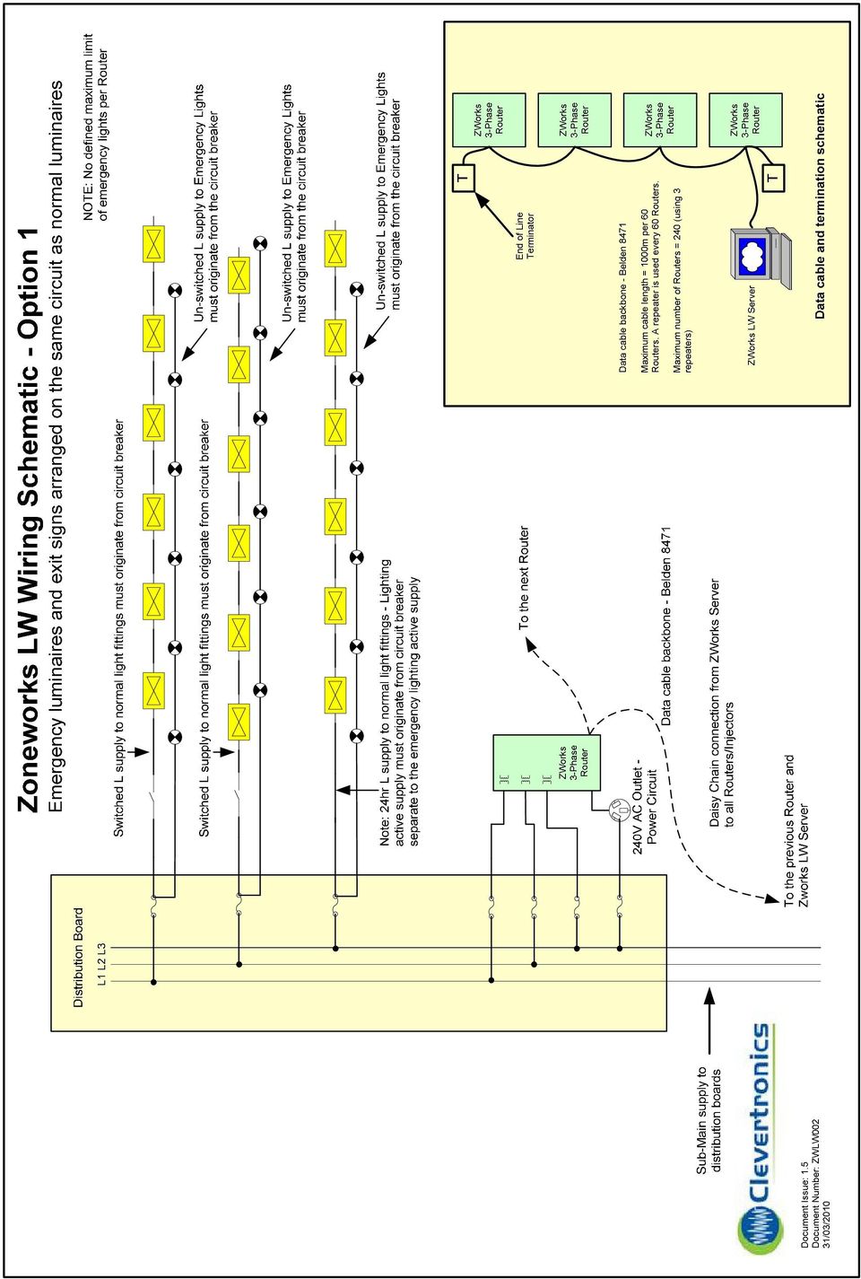
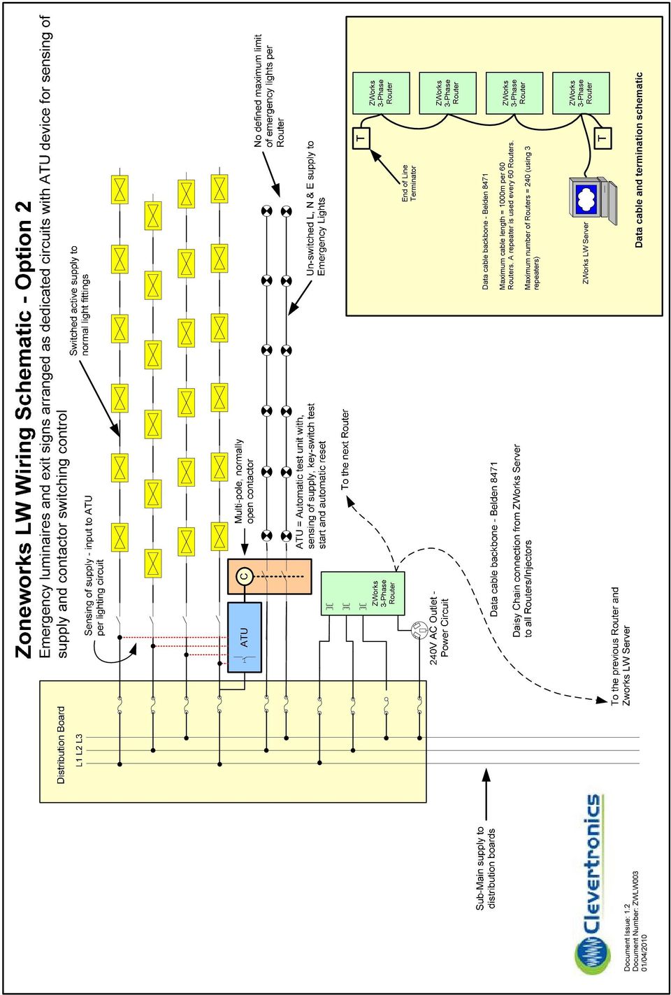
3 2. Example Topology: Typically, the Zoneworks Server is connected to the data cable backbone by a Lonworks TM USB Network Interface. From the Network Interface a data cable is Daisy Chained to all Distribution Boards that supply Emergency Lights to form the backbone of the system. At these distribution boards, 3-Phase Powerline Routers/Injectors are installed to communicate with each emergency luminaire over the Mains Supply wiring. The backbone data cable is connected to this Powerline Router. 3. System Design A PC Server is permanently connected to the Lonworks network and provides a means of significantly enhancing the capabilities of the system. The network consists of the Zoneworks Server connected to a network of routers and the luminaires are connected to the routers, typically via power line. There is a strong focus on extended and remote connectivity. Where extended connectivity is required the Zoneworks System can utilise data cable, fibre optic and LAN/WAN facilities for interconnection between buildings and remote control/monitoring is achieved via the Zoneworks WEB Service. 4. System backbone a) A daisy chained data cable must be run from the Server location to each Powerline Router. Cable Type: Belden 8471, Number of Pairs: 1, Total Number of Conductors: 2, AWG: 16, Stranding: 19x29, Conductor Material: TC - Tinned Copper, Insulation Material: PVC - Polyvinyl Chloride, Inner Shield Material: Unshielded, Outer Shield Material: Unshielded, Outer Jacket Material: PVC - Polyvinyl Chloride, Plenum (Y/N): N, Applications: Control and Instrumentation Cable b) Allow enough space within each relevant electrical distribution board cupboard to install the Zoneworks 3-Phase Router. Each Router will require a standard 240V socket outlet in addition to a 3- Phase Coupling to the Distribution Board. Router installation details are found within the 3-Phase Powerline Router Installation Guide. Router Dimensions: 250mm W x 240mm H x 65mm D. Please see the Clevertronics Zoneworks Systems Schematics on page 6 and 7 for comprehensive installation and wiring details. Page 3 of 10

4 5. Software The Zoneworks Software is designed to provide a simple but very powerful interface to the network of Zoneworks devices. Features: Real Time Status information this ensures that the latest information is available at all times and reduces the time spent polling the network. Group Test Scheduling Drag and Drop Group Allocation Visualisation of the Network Topology and Devices Automatic Database backup Windows Explorer based Tree View and List View Display Intuitive menu and command structure The Zoneworks software runs on the Clevertronics Zoneworks Server equipped with remote control capability via telephone line, LAN/WAN or the Internet - Zoneworks WEB Service. Please contact Clevertronics for further details. Zoneworks Interface Zoneworks Web Service and Interface Page 4 of 10

5 6. Compiling the database For smooth commissioning and end user operation, it is essential that accurate emergency luminaire information is compiled during installation. All the information you would normally require for a manual emergency lighting log book is also required for the Zoneworks system. Luminaire description, location, distribution board and circuit breaker information must be accurately recorded for the Zoneworks electronic log book. Zoneworks Luminaire Register Site : Clevertronics Pty Ltd Unit ID Number Unit Ref Luminaire Type Zone BLG Level /Floor DWG # Grid Ref Location S/B CCT Phase BARCODE Page of All Zoneworks emergency luminaires should be labeled with a user generated reference (Unit Ref) at the time of installation. The Unit Ref should be labeled clearly on the luminaire, and must be recorded accurately for successful system operation. All other information is entered into the electronic log book by the system installer. Clevertronics supply the above template for recording the required information (in electronic and hard copies) as part of the complete installation information. Note: The Unit ID (1 XXXXX) and the Luminaire Type is assigned automatically at the time of installation. The Unit Ref field can be entered by the user to suit an alternative labelling system. Several Barcode labels are provided with each luminaire. One label must be applied to the luminaire and one label must be applied onto the luminaire register (sticking the barcode label to construction drawings is optional). Commissioning of the Zoneworks System shall be in accordance with the Zoneworks Commissioning Guide. Page 5 of 10

6
7
8 7. Zoneworks System Specification The Emergency Lighting System shall provide group luminaire testing and individual real time monitoring facilities in addition to a software based electronic logbook in accordance with the requirements of the AS2293 suite of standards. The system shall be based upon Lonworks TM technology and utilize the power supply cables to the luminaires as the primary communication media. The system topology shall be such that a daisy chained data cable backbone connects a permanent system server to a network of Lonworks TM based FT(data cable) to powerline routers positioned at selected distribution boards around the site. These routers will couple the network information onto the 3-phase or single phase supply at the distribution board to facilitate communication to the luminaires. As a general rule an FT/powerline router will be required at each distribution board that supplies emergency lighting. The system server shall be specified by the manufacturer and the data cable must be Belden 8471 or approved equivalent. Luminaires All emergency luminaires within the system must be compatible with the system server and communication network. Luminaires shall use the Lonworks TM PL3120 Powerline transceiver to facilitate communication over the power cables and shall be capable of the following: Monitoring the battery voltage Monitoring the state of the emergency lamp in test Monitoring the state of the normal lamp (mains lamp) Storing the result of its last discharge test in non-volatile memory that is retained even after loss of both AC power and DC battery supply Support dynamic allocation of the network address - no pre-programming of network ID Support the LONMARK TM open systems object model and use standard network variables where available Software and System Server The System Software shall: Display graphical representations of the system server, routers and emergency luminaires Display Real time status information Provide the facility to create groups of emergency luminaires for testing and the ability to move devices between these different groups using drag & drop Provide reporting facilities capable of sorting by date, group and or device Provide the facility to replace of defective luminaires Provide the facility to program of multiple test groups to test at different times and dates Provide the facility to install routers and emergency luminaires and dynamically allocate the network address Display a summary of the system status and produce a simple report containing only defective emergency luminaires including location details Provide an Emergency Lighting Electronic Logbook detailing relevant location information (unit description, floor, DWG, grid ref, distribution board and circuit number), test results and maintenance history Provide local, LAN, WAN and WEB access to the network of emergency luminaires with the facility to remotely monitor the system status and view/print reports Page 8 of 10
 to powerline routers positioned at")
9 The System Server shall: Be connected to the device network at all times and shall be located in a suitable environment for computer based IT equipment. Be accessible at all times and must be used to install the routers and luminaires onto the network. Have access and be permanently connected to a broadband internet connection to facilitate the LAN, WAN and WEB control. Be specified and purchased from the Emergency Lighting System Manufacturer. Commissioning The system routers and emergency luminaires will be commissioned by pressing a momentary pushbutton at each device in conjunction with the installation module of the system software. Each router and emergency luminaire must be labeled with the network address assigned by the software but should also be labeled with a user reference that can be entered into the electronic logbook and used as the primary reference for the device. Location information is to be entered into the electronic logbook by the installing contractor at the time of installation and will be retained by the system server. A complete set of as installed drawings must be provided by the installing contractor detailing the following: The location of the system server, routers and emergency luminaires The data cable route between the server and routers The network and user ID of each emergency luminaire and router Page 9 of 10

10 Further information For more information, please contact your nearest Clevertronics office. Victoria/Tasmania Ph: Fax: New South Wales Ph: Fax: Queensland Ph: Fax: South Australia/Northern Territory Ph: Fax: [email protected] Western Australia Ph: Fax: [email protected] New Zealand Ph: Fax: [email protected] Please note: Clevertronics make every effort to ensure information supplied is accurate, however, the installing contractor or specifier should ensure that the installation is compliant with all relevant codes and standards and information such as provided here is accurate and up to date with any changes or revisions that may apply at the time of design and installation. References (Text and Images): 1. Powerline Communication Technology Update (presentation), Echelon Corporation 2. Evaluating Power Line Environments Using the Echelon PLCA-22 Communication Analyzer (presentation), Echelon Corporation 3. Designing with the Power Line Smart Transceiver (presentation), Echelon Corporation Page 10 of 10

Evacuation Lighting Management System
 Evacuation Lighting Management System ARE YOU PREPARED FOR AN EMERGENCY? In the interest of public safety, the Australian Standard AS/NZS 2293.2 outlines the obligations of building owners/ managers, in
SECTION 13850 (28 31 00) FIRE DETECTION AND ALARM SYSTEM
 FIRE DETECTION AND ALARM SYSTEM") SECTION 13850 (28 31 00) FIRE DETECTION AND ALARM SYSTEM ENGINEERING SPECIFICATION INTELLIGENT REPORTING FIRE DETECTION SYSTEM PART 1 GENERAL 1.1 DESCRIPTION A. This specification includes the furnishing,
SECTION 13850 (28 31 00) FIRE DETECTION AND ALARM SYSTEM ENGINEERING SPECIFICATION INTELLIGENT REPORTING FIRE DETECTION SYSTEM PART 1 GENERAL 1.1 DESCRIPTION A. This specification includes the furnishing,
Security & Control Cables
 Security & Control Cables Our multi-conductor cables are manufactured in a wide variety of gage sizes, shielding configurations and jacketing materials including plenum, riser and general purpose. Applications
Functional Specification Document
 Functional Specification Document Access Control Technology Unit C1 South City Business Centre Tallaght Dublin 24 Ireland Ph: + 353 (0) 1 4662570 Web: www.accesscontrol.ie Index Introduction 1.1 Hardware
Datasheet. 802.11n Wireless Router Models: AR, AR-HP. Fast 150 Mbps Wireless Speed. Long Range Up to 200+ Meters
 802.11n Wireless Router Models: AR, AR-HP Fast 150 Mbps Wireless Speed Long Range Up to 200+ Meters Powered by Ubiquiti s airos Technology Wireless Router or Bridge Modes Introducing the airrouter featuring
Technical Description U00980 Revision 2
 Technical Description U00980 Revision 2 TLON Author: Mikael Rivarola Date of issue: 2000-01-07 Date of rev: 2009-01-30 Table of contents 1 Introduction 2 2 Definitions / Explanations 3 3 General description
Networks. The two main network types are: Peer networks
 Networks Networking is all about sharing information and resources. Computers connected to a network can avail of many facilities not available to standalone computers: Share a printer or a plotter among
Application/Connection Examples
 This Quick Start Guide is designed to familiarize the user with the connection and configuration of the DTS-305 DIN rail mounted single / 3 phase power & energy meter with RS-485 or TCP communications.
Electronics Ltd. Presenting. Power, Intelligence... with a sense of feeling
 Electronics Ltd Presenting Power, Intelligence... with a sense of feeling By Appointment to Her Majesty The Queen Supplier of Fire Detection Equipment Kentec Electronics Ltd. Dartford Plug in slots K772
DSX Master Communications
 DSX Access Systems, Inc. PC to Master Controller - Direct Connect Communications DSX Master Communications Communications between the Comm Server PC and the Master Controller can take several forms which
MAKING MODERN LIVING POSSIBLE. AK-SC255 On-Site Installation Guide DANFOSS ELECTRONIC CONTROLS & SENSORS
 MAKING MODERN LIVING POSSIBLE AK-SC255 On-Site Installation Guide DANFOSS ELECTRONIC CONTROLS & SENSORS How to Use This Guide Read this Guide completely as you install and start up your new AK-SC 255 controller.
Data Bulletin. Communications Wiring for POWERLINK G3 Systems Class 1210 ABOUT THIS BULLETIN APPLICATION INTRODUCTION.
 Data Bulletin 1210DB0002R3/05 03/2005 LaVergne, TN, USA Communications Wiring for POWERLINK G3 Systems Class 1210 Retain for future use. ABOUT THIS BULLETIN This data bulletin describes the proper wiring
802.11n Wireless Router. Datasheet. Models: AR, AR-HP. Fast Wireless Speed Up to 150 Mbps. Long Range Up to 200+ Meters
 Datasheet 802.11n Wireless Router Models: AR, AR-HP Fast Wireless Speed Up to 150 Mbps Long Range Up to 200+ Meters Powered by Ubiquiti s airos Technology Wireless Router or Bridge Modes Datasheet Introducing
NMEA 0183 INSTALLATION AND OPERATING GUIDELINES
 NMEA 0183 INSTALLATION AND OPERATING GUIDELINES Revised July 2010 8.1.3 Documentation The following documentation shall be provided to the owner for each interfaced system and shall be kept on file by
CN1047 INTRODUCTION TO COMPUTER NETWORKING CHAPTER 1 BASIC CONCEPTS OF NETWORK
 CN1047 INTRODUCTION TO COMPUTER NETWORKING CHAPTER 1 BASIC CONCEPTS OF NETWORK DEFINTION & APPLICATIONS DEFINTION: A computer network is defined as the interconnection of two or more computers. It is done
EQUIPMENT SPECIFICATIONS
 EQUIPMENT SPECIFICATIONS IC-1600 Intelligent Controller The IC-1600 Intelligent Controller is a fully intelligent panel that has a complete database on board. It operates in conjunction with the Access
Solar monitoring gateway quick start guide
 Instructional Leaflet I70002E LGATE101-1B LGATE101-1A LGATE101-5B LGATE101-5A Contents Description Page General................................. 2 Information collection sheet............... 2 Quick reference
Technology Spotlight on Cellular Data Networking for SCADA system networks. Presented by Teamwork Solutions, Inc.
 on Cellular Data Networking for SCADA system networks Presented by Teamwork Solutions, Inc. Wireless (Cellular) Data Networking Internet SCADA Server How Wireless (Cellular) Data Networking Works Dynamic
ADACSNET USB Control Module
 ADACSNET USB Control Module Installation Guide Termination Switch 2-Pin SensorNet Connection Features and Hookup The USB Control Module contains the following: - USB port: Connects to the host computer.
Access control designed simply for you
 TruPortal Access control designed simply for you QUICK START GUIDE Introduction TruPortal access control solutions have been engineered and designed to install quickly and easily right out of the box.
MechoNet TM Network Interface (MNI) Specification Submittal
 Specification Submittal") MechoNet TM Network Interface (MNI) Specification Submittal Models MechoNet Network Interface: MNI RJ (RJ45 Motor Ports): Stock No.: IMNI 0001 TP AS (US version) Stock No.: IMNI 0004 TP AS (UK version)
MechoNet TM Network Interface (MNI) Specification Submittal Models MechoNet Network Interface: MNI RJ (RJ45 Motor Ports): Stock No.: IMNI 0001 TP AS (US version) Stock No.: IMNI 0004 TP AS (UK version)
Ozbytes Design Biometric Fingerprint Time and Attendance and Access Control Unit Item Code: OZD-ABC-AV100
 Biometric Fingerprint Time and Attendance and Access Control Unit Item Code: OZD-ABC-AV100 The OZD-ABC-AV100 Biometric Fingerprint Time and Attendance and Access Control Unit is a Professional Time and
FVSU-33201301 REPAIR & UPGRADE FIBER OPTIC 280000-1 SECTION 280000 FIRE ALARM SYSTEM CONNECTIVITY
 FVSU-33201301 REPAIR & UPGRADE FIBER OPTIC 280000-1 SECTION 280000 FIRE ALARM SYSTEM CONNECTIVITY PART 1 - GENERAL 1.1 SUMMARY A. Section Includes: 1. Fire-alarm control unit. 2. Addressable interface
HP-1000 Powerline USB Adapter
 HP-1000 Powerline USB Adapter User s manual BEFORE INSTALLATION Plan ahead the installation of your powerline network. Note: You will need at least two powerline adapters to create a powerline network.
Installation Manual For Support Call 01704 807114 or email [email protected]
 Installation Manual Hip Smart Hub (Standard BT and BT FTTP Sites) The Home Network Hub houses the Home Owner s Broadband Router and connects the hardwired network ports on that Router to three network
HP-1000 Powerline Ethernet Adapter
 HP-1000 Powerline Ethernet Adapter User s manual BEFORE INSTALLATION Plan ahead the installation of your powerline network. Note: You will need at least two powerline adapters to create a powerline network.
TAXONOMY OF TELECOM TERMS
 TAXONOMY OF TELECOM TERMS Prepared by TUFF Ltd This short taxonomy is designed to describe the various terms used in today s telecommunications industry. It is not intended to be all embracing but to describe
Agenda Introduction to KNX UK What is KNX? KNX the all round advantages The Standards Manufacturers & Products KNX Technology Applications KNX is
 Agenda Introduction to KNX UK What is KNX? KNX the all round advantages The Standards Manufacturers & Products KNX Technology Applications KNX is Green KNX Projects Questions? The KNX UK Association National
LIGHTIFY Pro Commissioning and control (Tablet / Smart Phone)
") LIGHTIFY Pro Commissioning and control (Tablet / Smart Phone) via Smart Device Content Welcome to LIGHTIFY Pro Page 3. LIGHTIFY Pro system overview and operating principle 3 2. Installation information
LIGHTIFY Pro Commissioning and control (Tablet / Smart Phone) via Smart Device Content Welcome to LIGHTIFY Pro Page 3. LIGHTIFY Pro system overview and operating principle 3 2. Installation information
PXL-250: Network Wiring
 This document provides the network wiring requirements for a PXL-250 access control network. Network Requirements The PXL-250 uses a half-duplex, RS-485 communication bus. Per the RS-485 specification,
DL TC72 Communication Protocols: HDLC, SDLC, X.25, Frame Relay, ATM
 DL TC72 Communication Protocols: HDLC, SDLC, X.25, Frame Relay, ATM Objectives: Base training of an engineer for the installation and maintenance of Digital Telecommunications and Internetworking systems.
Presenters Brett Weiss, Gabe Martinez, Brian Kroeger.
 1 Presenters Brett Weiss, Gabe Martinez, Brian Kroeger. Topics to be covered: Cable identification Purpose of the various cable types Installation techniques Building Infrastructure Overview of networking
Core Syllabus. Version 2.6 C OPERATE KNOWLEDGE AREA: OPERATION AND SUPPORT OF INFORMATION SYSTEMS. June 2006
 Core Syllabus C OPERATE KNOWLEDGE AREA: OPERATION AND SUPPORT OF INFORMATION SYSTEMS Version 2.6 June 2006 EUCIP CORE Version 2.6 Syllabus. The following is the Syllabus for EUCIP CORE Version 2.6, which
ZigBee-2.4-DK 2.4 GHZ ZIGBEE DEVELOPMENT KIT USER S GUIDE. 1. Kit Contents. Figure 1. 2.4 GHz ZigBee Development Kit
 2.4 GHZ ZIGBEE DEVELOPMENT KIT USER S GUIDE 1. Kit Contents The 2.4 GHz ZigBee Development Kit contains the following items, shown in Figure 1. 2.4 GHz 802.15.4/ZigBee Target Boards (6) Antennas (6) 9
Turbo 85 Mbps Powerline Ethernet Adapter Model # APL8512. User s Manual. Ver. 1A
 Turbo 85 Mbps Powerline Ethernet Adapter Model # APL8512 User s Manual Ver. 1A Table of Contents 1. Introduction... 3 1.1 Package Contents... 3 1.2 Features... 3 2. Installing Adapters... 4 3. Installing
Cisco Unified IP Conference Phone 8831 Installation
 Cisco Unified IP Conference Phone 8831 Installation Cisco Unified IP Conference Phone 8831 Installation Overview, page 1 Before You Begin, page 1 Cisco Unified IP Conference Phone 8831 Components, page
Planning BACnet networks
 Digital Designer s Guide Application Note AN0404A Revision B About this application note Related reference materials Required software This application note describes the principles behind planning a BACnet
System Wiring Design Guide
 System Wiring Design Guide This guide will help demonstrate the various types of wiring solutions available when connecting video surveillance cameras to EZ Watch Pro and Armor Pro Digital Video Recorders.
Performance Verification of GigaSPEED X10D Installations with Fluke Networks DTX 1800 CableAnalyzer
 SYSTIMAX Solutions Performance Verification of GigaSPEED X10D Installations with Fluke Networks DTX 1800 CableAnalyzer Issue 2 Draft 1 June 2010 Contents Overview 3 GigaSPEED X10D Guaranteed Channel Performance
Structured Cabling, Earthing & Equipotential Bonding
 White Paper Information and Communication Technology Structured Cabling, Earthing & Equipotential Bonding English Rev. 1.0.1 / 2012-06-01 1 Abstract All Dallmeier network products (PoE cameras, recorders,
ELCOMPONENT LTD. User Manual
 ELCOMPONENT LTD R-DCU - Remote Data a Collection Unit User Manual al CONTENTS Page 1. GENERAL... 1 2. SPECIFICATION... 4 3. INSTALLATION AND INSTRUCTIONS... 6 4. INSTRUMENT SET-UP AND RESET... 11 All rights
Comm5 Wiring Installation
 Comm5 Wiring Installation This wiring information applies to the following Trane products: Tracer Summit systems (Comm5 communications, Version 12.0 and higher) Tracker systems (BMTK models) Tracer loop
Network Technologies
 Network Technologies Career Cluster Information Technology Course Code 10101 Prerequisite(s) Introduction To Information Technology Careers (Recommended), Computer Applications (Recommended), Computer
AV1200 TL-PA8030P KIT. 3-Port Gigabit Passthrough Powerline Starter Kit. Highlights
 AV1200 3-Port Gigabit Passthrough Powerline Starter Kit Highlights AV1200 HomePlug AV2 standard compliant, high-speed data transfer rates of up to 1200Mbps, supports all your online needs MIMO Technology
Network Design. Yiannos Mylonas
 Network Design Yiannos Mylonas Physical Topologies There are two parts to the topology definition: the physical topology, which is the actual layout of the wire (media), and the logical topology, which
DIVISION 26 - ELECTRICAL SECTION 26 05 20 CABLES FOR INSTRUMENTATION
 DIVISION 26 - ELECTRICAL PART 1 - GENERAL 1.01 SUMMARY A. Section Includes 1. Instrumentation Cables 1.02 SUBMITTALS A. Submit in accordance with requirements of Section 01 33 00. B. Product Data: Submit
White paper. Intelligent networks
 White paper Intelligent networks Intelligent networks reducing the need for on-site maintenance Networks are evolving constantly. The number of subscribers is increasing and new services require more network
1394 locking cables. Your locking cables for AVT IEEE 1394 cameras
 Your locking cables for AVT IEEE 1394 cameras AVT locking cables are ideal for connection of IEEE 1394 cameras in any industrial application. The high quality cables guarantee low damping and best signal
ICTNPL5071A Develop planning strategies for core network design
 ICTNPL5071A Develop planning strategies for core network design Release: 1 ICTNPL5071A Develop planning strategies for core network design Modification History Not Applicable Approved Page 2 of 15 Unit
RoHS DATA, COAXIAL AND ELECTRONIC M.R. D A TA, C O A X I A L, ECOLGICAL Telecom Cables A N D EL E CTRON I C. Cables
 RoHS DATA, COAXIAL AND ELECTRONIC D A TA, C O A X I A L, A N D EL E CTRON I C Cables Index SOLID MULTI-CONDUCTOR CABLES STRANDED MULTI-CONDUCTOR CABLES SPEAKER/ZIP WIRE THERMOSTAT CABLE FIRE ALARM CABLE
WiFi and Security Administration
 S&C PulseCloser Outdoor Distribution (15.5 kv, 27 kv, and 38 kv) WiFi and Security Administration Table of Contents Section Page Section Page Introduction Qualified Persons...2 Read this Instruction Sheet....2
PowerCommand iwatch 100
 PowerCommand iwatch 100 Remote Network Monitoring Description The PowerCommand iwatch 100 system provides convenient means for remotely monitoring generator sets and transfer switches that are interconnected
Power over Ethernet technology for industrial Ethernet networks
 Power over Ethernet technology for industrial Ethernet networks Introduction Ethernet networking has grown beyond office and home usage to become a very successful protocol suite used in many industrial
Think! Think! Data communications. Long-Distance. Modems: to analog and back. Transmission Media. The last mile is the hardest for digital information
 Data communications Think! Think!?? What makes it possible to communicate from point A to point B?? Long-Distance Transmission Media If you place a call outside the local transport area, an interchange
Documentation. M-Bus 130-mbx
 Documentation M-Bus 130-mbx Introduction The mx M-Bus module is part of the mx Smart Slot communications family. With the integrated SmartSlot technology, mx systems ag offers automatic consumer data read-out
ARE YOU WIRING FOR A SMART HOME? Guidelines for homeowners on the wiring requirements for telecommunications and other wired services.
 ARE YOU WIRING FOR A SMART HOME? Guidelines for homeowners on the wiring requirements for telecommunications and other wired services. INTRODUCTION Installing the right wiring when building or renovating
C-Bus Network Monitor
 C-Bus Network Monitor Installation Instructions 5500NMA Copyright Clipsal Integrated Systems Pty Ltd 2004. All rights Reserved. This material is copyright under Australian and international laws. Except
TI 313 (1.0 EN) d&b Remote network - Integration
 d&b Remote network - Integration") TI 313 (1.0 EN) d&b Remote network - Integration 1. Introduction The d&b Remote network offers various options to configure, control and monitor a d&b sound reinforcement system. This can be done by either
TI 313 (1.0 EN) d&b Remote network - Integration 1. Introduction The d&b Remote network offers various options to configure, control and monitor a d&b sound reinforcement system. This can be done by either
Quick & Easy Set-Up of Packet8 Internet Phone Service
 For the Way You Live & Work Quick & Easy Set-Up of Packet8 Internet Phone Service Welcome to Packet8 Internet Phone Service. Soon, you ll be able to make all your calls over the Internet and save a bundle
Home Network. Installation Instructions
 Home Network Installation Instructions TM Installation Instructions Table of Contents Overview...2 Installation Considerations...2 Quick Installation Instructions...2 Identifying and Creating the Home
Unarmored Variable Frequency Drive (VFD) Cable Termination Guide
 Cable Termination Guide") Authorized Distributor Unarmored Variable Frequency Drive (VFD) Cable Termination Guide Be Certain with Belden A Step-by-Step Look at the Connection/Termination of Unarmored VFD Cables Terminating Unarmored
Authorized Distributor Unarmored Variable Frequency Drive (VFD) Cable Termination Guide Be Certain with Belden A Step-by-Step Look at the Connection/Termination of Unarmored VFD Cables Terminating Unarmored
1.3. The network element must have the ability to be configured in a point to point, point to multi point, and daisy chain configuration.
 DESCRIPTION This work shall consist of furnishing and installing 10/100 Ethernet over Twisted Pair (TWP) Copper Modems in accordance with the contract documents and as directed by the Engineer. MATERIALS
Installation Guide Solar Connect-11
 Installation Guide Solar Connect-11 Version 1.1 Contents Important Product Information 3 System Registration Form 4 Solar Connect-11 Overview 5 Internet & Power Connections 6 Single Phase CT Connections
Cable Products HONEYWELL SECURITY & CUSTOM ELECTRONICS. Honeywell's Genesis Series provides a full range
 HONEYWELL SECURITY & CUSTOM ELECTRONICS Cable Products Honeywell's Genesis Series provides a full range of low voltage cables for security, fire, sound, voice and data, video, structured cabling and other
UNDERSTANDING. C&M Corporation 51 South Walnut Street, Wauregan, CT 06387 Phone: 860.774.4812 Fax: 860.774.7330 www.cmcorporation.
 UNDERSTANDING UNDERSTANDING NFPA 79 By Ned Lloyd and Mike Levesque NFPA-79 is the electrical standard that has been developed by the National Fire Protection Association (NFPA) and is intended to minimize
ISHIDA BC-3000. Scale to Scale Communications
 ISHIDA BC-3000 Scale to Scale Communications Setup Procedure & Operating Instructions March 2006 PN 94561 Revision History Date Page Description March 2006 Initial publication August 2006 2 Added RS-232
Simplify Data Acquisition with a Built-in LXI Web Server
 M E A S U R E M E N T T I P S Volume 9, Number 3 Simplify Data Acquisition with a Built-in LXI Web Server Snapshot: Make temperature measurements quickly and easily There are many applications in which
User manual Rev 1.3 Contents
 User manual Rev 1.3 Contents 1. Introduction...4 2. System specifications...5 2.1.. General overview...5 2.2. Maximum capacity...6 2.3. Electrical specifications...6 2.4. Mechanical specifications...6
SECTION 271525 OPTICAL FIBER CABLES AND ACCESSORIES. A. Interior Raceways, Fittings, and Accessories: Section 260532.
 SECTION 271525 OPTICAL FIBER CABLES AND ACCESSORIES PART 1 GENERAL 1.01 RELATED WORK SPECIFIED ELSEWHERE A. Interior Raceways, Fittings, and Accessories: Section 260532. B. Wiring, General - 600 Volts
Trial Exams C. Standards and Regulations. Examination No: GH-08-C- 1 hour and 5 minutes plus 10 minutes reading time
 Trial Exams C Standards and Regulations Examination No: GH-08-C- This test is intended to gauge your knowledge of essential information contained within AS/CA S009:2013. To qualify for an allpication to
Honeywell Internet Connection Module
 Honeywell Internet Connection Module Setup Guide Version 1.0 - Page 1 of 18 - ICM Setup Guide Technical Support Setup - Guide Table of Contents Introduction... 3 Network Setup and Configuration... 4 Setting
Ontario Electrical Safety Code 25 th Edition/ 2012
 Ontario Electrical Safety Code 25 th Edition/ 2012 Ted Olechna Director, Codes and Standard Chief Engineer 1 What I Will Cover ESA s role is as the regulator Highlight of 2012 Code changes The Code and
SECTION 17400 ACCESS CONTROL SYSTEM. CONDITIONS OF THE CONTRACT AND DIVISION 1, as applicable, apply to this Section.
 SECTION 17400 ACCESS CONTROL SYSTEM CONDITIONS OF THE CONTRACT AND DIVISION 1, as applicable, apply to this Section. PART 1 - GENERAL 1.1 RELATED WORK A. 16060 Grounding and Bonding B. 16070 Electrical
SECTION 25 15 16 INTEGRATED AUTOMATION SOFTWARE FOR CONTROL OF MONITORING NETWORKS
 SECTION 25 15 16 INTEGRATED AUTOMATION SOFTWARE FOR CONTROL OF MONITORING NETWORKS Specifier: The Specifier/Design Professional is responsible for the accuracy of all project specifications, including
Chapter 4 Connecting to the Internet through an ISP
 Chapter 4 Connecting to the Internet through an ISP 1. According to Cisco what two things are essential to gaining access to the internet? a. ISPs are essential to gaining access to the Internet. b. No
Fibre Optic Solutions for your Test and Instrumentation needs
 Fibre Optic Solutions for your Test and Instrumentation needs Aerospace Test EMC/EMP Military Industrial Control High Energy Physics Automotive Test Custom www.point2point.co.uk Fibre Optic Solutions for
Parallel Redundant Uninterruptible Power Supply
 9 315 Parallel Redundant Uninterruptible Power Supply Installation/Operation Manual 164202013 Rev. D ------------------------------------------------------------------------ ------------------------------------------------------------------------
Using installed Fieldbus Wiring to carry Ethernet Communications
 Using installed Fieldbus Wiring to carry Ethernet Communications Modbus Plus, Data Highway, GE Genius, Profibus, ControlNet, DeviceNet, InterbusS and many other RS232 or RS4422 cables Key Issues when upgrading
Installation Guide for Hive Active Heating
 Installation Guide for Hive Active Heating Important note: Installation should only ever be carried out by a qualified engineer. Technical Support If you need to contact Hive s Technical Support team during
Smart Cloud Solutions
 home2net GmbH Smart Cloud Solutions May 2015 Did you notice? IOT development Industrial IOT IHS 2013: Internet Connected Devices Implications 50.000.000.000 IOT device's in 2020 highest prediction is 200.000.000.000
Vertex VoIP Caller ID (Version 1.5)
") Vertex VoIP Caller ID (Version 1.5) Introduction The Vertex unit is designed to capture Caller ID and other telephony signaling on VoIP phone calls and send this information to computers. Depending on
Vertex VoIP Caller ID (Version 1.5) Introduction The Vertex unit is designed to capture Caller ID and other telephony signaling on VoIP phone calls and send this information to computers. Depending on
Siemens Integrated Substation Condition Monitoring System. Circuit Breaker Monitoring
 Siemens Integrated Substation Condition Monitoring System Circuit Breaker Monitoring System Description Introduction The Circuit Breaker Monitor [CBM] is only one example of the way that the Substation
DENVER PUBLIC SCHOOLS DESIGN AND CONSTRUCTION STANDARDS This Standard is for guidance only. SECTION 17650 SECURITY SYSTEMS
 PART 0 DESIGN STANDARDS 0.01 GENERAL DESIGN GUIDELINES A. Inspections and observations by the Owner do not relieve the A/E of contract responsibilities. B. Chain of command 1. The DPS Project Manager is
NJP-400A NJP-401A. Safely into a new day. Advanced modular FIRE ALARM CONTROL PANEL with additional functionality. I m on FIRE (Bruce Springsteen)
") Safely into a new day Advanced modular FIRE ALARM CONTROL PANEL with additional functionality NJP-400A NJP-401A I m on FIRE (Bruce Springsteen) EN 54-2, EN 54-4 Cert No. 1124a DESCRIPTION OP-400A, NJP-400A,
Safely into a new day Advanced modular FIRE ALARM CONTROL PANEL with additional functionality NJP-400A NJP-401A I m on FIRE (Bruce Springsteen) EN 54-2, EN 54-4 Cert No. 1124a DESCRIPTION OP-400A, NJP-400A,
EVC40 EMERGENCY VOICE COMMUNICATION SYSTEM
 EVC40 EMERGENCY VOICE COMMUNICATION SYSTEM INSTALLATION MANUAL Protec Fire Detection PLC, Protec House, Churchill Way, Nelson, Lancashire, BB9 6RT. Telephone: +44 (0) 1282 717171 Fax: +44 (0) 1282 717273
POPP Hub Gateway. Manual
 POPP Hub Gateway Manual 008900 POPP Hub Gateway Manual Quick Start... 2 Hardware... 2 Smart Home User Interface... 2 Applications (Apps) realize the intelligence of your Smart Home... 3 Functions of the
INTERIM MARKET DOCUMENT CHANGE
 INTERIM MARKET DOCUMENT CHANGE Title: MPLS and Alternative Communications for Medium Performance Facilities File #: IESO_IMDC_0169 Version #: 0.2 Part 1 General Information Document Affected: Market Manual
SECTION 26 09 26 LOW VOLTAGE LIGHTING CONTROLS
 SECTION 26 09 26 LOW VOLTAGE LIGHTING CONTROLS PART 1 - GENERAL 1.01 RELATED DOCUMENTS: A. The Conditions of the Contract and applicable requirements of Division 1, "General Requirements", and Section
Chapter 18. Network Management Basics
 Network Management Basics > FCAPS Model Chapter 18. Network Management Basics This chapter covers the following topics: FCAPS Model Network Management Architecture Network Management Protocols An Introduction
Networking 101 (Networking Basics) Presentation to UCHUG - 1/03/07 G. Skalka
 Presentation to UCHUG - 1/03/07 G. Skalka") Networking 101 (Networking Basics) Presentation to UCHUG - 1/03/07 G. Skalka What is a network? A computer network is two or more computers connected together using a telecommunication system for the purpose
Networking 101 (Networking Basics) Presentation to UCHUG - 1/03/07 G. Skalka What is a network? A computer network is two or more computers connected together using a telecommunication system for the purpose
Installation instructions for Series NRX INCOM communications adapter module
 4000 NRX RF DRAWOUT SUBTITLE IMAGE (12/15/2010) Effective July 2015 Supersedes October 2010 IL01301033EH04 Installation instructions for Series NRX INCOM communications adapter module Instructions apply
Nathan Dayton ADNET. ADNET SYSTEMS, Inc. [email protected]. Slide Number 1
 Nathan Dayton SYSTEMS, Inc. [email protected] Slide Number 1 NETWORK DESIGN Slide Number 2 Previously there have been two phases in the design of a network Department Design Interconnect Design
R-Win. Smart Wireless Communication Management System
 Smart Wireless Communication Management System General R-Win is a smart communications adapter for management of wireless communications in a SCADA/Distributed Control System. The R-Win system includes
Local Area Networks (LANs) Blueprint (May 2012 Release)
 Blueprint (May 2012 Release)") Local Area Networks (LANs) The CCNT Local Area Networks (LANs) Course April 2012 release blueprint lists the following information. Courseware Availability Date identifies the availability date for the
Local Area Networks (LANs) The CCNT Local Area Networks (LANs) Course April 2012 release blueprint lists the following information. Courseware Availability Date identifies the availability date for the
JT Fibre is here What to expect as a new JT Fibre customer
 JT Fibre is here What to expect as a new JT Fibre customer Congratulations on connecting to the new JT Fibre Network This next generation technology will ensure we all have the communication services we
Temperature & Humidity SMS Alert Controller
 Temperature & Humidity Alert Controller METERS 3 simple steps starting the unit: Insert the SIM card Plug in the sensors connectors Connect the AC power cord. Specifications: AC 90~260V Auto Select Internal
Setting Up the Cisco Unified IP Phone
 CHAPTER 3 This chapter includes the following topics, which help you install the Cisco Unified IP Phone on an IP telephony network: Before You Begin, page 3-1 Understanding the Cisco Unified IP Phone 7962G