USB dedicated charging port (DCP) controller
|
|
|
- Erin Wells
- 10 years ago
- Views:
Transcription
1 USB dedicated charging port (DCP) controller BL2513A DESCRIPTION The BL2513A is USB dedicated charging port (DCP) controllers. Applications include vehicle power charger, wall adapters with USB DCP and other USB chargers. The BL2513A controller has the auto-detect feature that monitors the D+ and D line voltages of the USB connector, providing the correct electrical signatures on the DP and DM pins for the correct detections of compliant portable devices to fast charge. These portable devices include smart phones, 5-V tablets and personal media players. The BL2513A support five of the most common protocols: Divider 3 (DCP Applying 2.7V on D+ Line and 2.7V on D Line) USB Battery Charging Specification, Revision 1.2 (BC1.2) Chinese Telecommunications Industry Standard YD/T V on both D+ and D lines FEATURES In accordance with USB Battery Charging Specification, Revision 1.2 (BC1.2), support USB DCP D+ line shorted to D- line. In accordance with Chinese Telecommunications Industry Standard YD/T , support Short mode. ( support D+ line shorted to D- line) Support DCP applying 2.7 V on D+ Line and 2.7 V on D Line, Support DCP applying 1.2V to the D+ Line and 1.2V to the D Line Automatic switching D+ Line and D- Line for connected devices. Double USB port controller. Operation voltage range from 4.5V to 5.5V APPLICATIONS USB car charger AC-DC adapter with USB port Other USB charger 1 V1.0

2 BLOCK DIAGRAM PIN CONFIGURATION PIN DESCRIPTION No. Name Type description Connected to the D+ or D line of USB connector, provide the 1 DP1 I/O correct voltage with attached portable equipment for DCP detection. 2 GND G Ground connection 3 DP2 I/O 4 DM2 I/O 5 IN P 6 DM1 I/O Connected to the D+ or D line of USB connector, provide the correct voltage with attached portable equipment for DCP detection. Connected to the D+ or D line of USB connector, provide the correct voltage with attached portable equipment for DCP detection. Power supply. Connect a ceramic capacitor with a value of 0.1-µF or greater from the IN pin to GND as close to the device as possible. Connected to the D+ or D line of USB connector, provide the correct voltage with attached portable equipment for DCP detection. 2 V1.0

3 ABSOLUTE MAXIMUM RATINGS * Over recommended junction temperature range, voltages are referenced to GND (unless otherwise noted) Characteristic Conditions Min. Max. Unit IN Voltage range DP1,DP2 output voltage, DM1,DM output voltage V DP1,DP2 input voltage, DM1,DM2 input voltage DP1,DP2 input voltage, DM1,DM2 Continuous output sink current input voltage 35 ma Continuous output source DP1,DP2 output voltage, DM1,DM2 current output voltage 35 ma Operating junction temperature T J Storage temperature range Tstg ESD (human body mode) 8000 V *Stresses beyond those listed under Absolute Maximum Ratings may cause permanent damage to the device. These are stress ratings only, and functional operation of the device at these or any other conditions beyond those indicated under Recommended Operating Conditions is not implied. Exposure to absolute-maximum-rated conditions for extended periods may affect device reliability. THERMAL INFORMATION Thermal metrc Symbol DBV Unit Junction-to-ambient thermal resistance θ JA Junction-to-case (top) thermal resistance θ JCtop Junction-to-board thermal resistance θ JB 41.9 Junction-to-top characterization parameter ψ JT 17.2 Junction-to-board characterization parameter ψ JB 41.5 Junction-to-case (bottom) thermal resistance θ JCbot N/A /W RECOMMENDED OPERATING CONDITIONS Voltages are referenced to GND (unless otherwise noted), positive current are into pins. Characteristic Symbol Min. Max. Unit Input voltage of IN V IN V DP1 data line input voltage V DP V DM1 data line input voltage V DM V Continuous sink or source current I DP1 ±10 ma Continuous sink or source current I DM1 ±10 ma DP2 data line input voltage V DP V DM2 data line input voltage V DM V Continuous sink or source current I DP2 ±10 ma Continuous sink or source current I DM2 ±10 ma Operating junction temperature T J V1.0

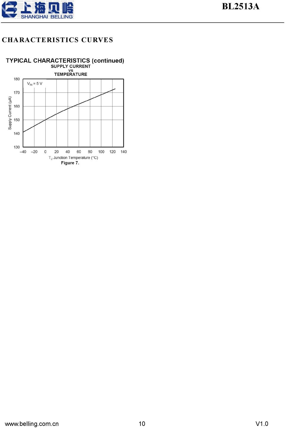
4 ELECTRICAL CHARACTERISTICS Conditions are 40 C (T J = T A ) 125 C, 4.5V V IN 5.5V. Positive current are into pins. Typical values are at 25 C. All voltages are with respect to GND (unless otherwise noted). Characteristic Symbol Conditions Min. Typ. Max Unit Undervoltage Lockout IN rising UVLO threshold voltage V UVLO V Hysteresis 100 mv Supply Current IN supply current I IN 4.5 V V IN 5.5 V µa BC 1.2 DCP Mode(Short Mode) DP1 and DM1 shorting resistance Resistance between DP1/DM1 and GND Voltage threshold on DP1 under which the device goes back to divider mode Hysteresis DP2 and DM2 shorting resistance Resistance between DP2/DM2 and GND Voltage threshold on DP2 under which the device goes back to divider mode Hysteresis R DPM_SHOR T1 R DCHG_SHO RT1 V DPL_TH_D ETACH1 V DPL_TH_D ETACH_HYS 1 R DPM_SHOR T2 R DCHG_SHO RT2 V DPL_TH_D ETACH2 V DPL_TH_D ETACH_HYS 2 V DP1 =0.8V, I DM1 = 1mA V DP1 =0.8V V DP2 =0.8V, I DM2 = 1mA V DP2 =0.8V Ω kω mv 50 mv Ω kω mv 50 mv Divider Mode DP1 output voltage V DP1_2.7V V IN =5V V DM1 output voltage V DM1_2 7V V IN =5V V DP1 output impedance R DP1_PAD1 I DP1 =-5µA kω DM1 output impedance R DM1_PAD1 I DM1 =-5µA kω DP2 output voltage V DP2_2.7V V IN =5V V DM2 output voltage V DM2_2.7V V IN =5V V DP2output impedance R DP2_PAD1 I DP2 =-5µA kω DM2output impedance R DM2_PAD1 I DM2 =-5µA kω 1.2V/1.2V Mode DP1 output voltage V DP1 V IN =5V V DM1 output voltage V DM1 V IN =5V V DP1 output impedance R DP1_PAD1 I DP1 =-5µA kω 4 V1.0
 DP1 and DM1 shorting resistance Resistance between DP1/DM1 and GND Voltage threshold on DP1 under which the device goes back to divider mode Hysteresis DP2 and DM2 shorting")
5 DM1 output impedance R DM1_PAD1 I DM1 =-5µA kω DP2 output voltage V DP2 V IN =5V V DM2 output voltage V DM2 V IN =5V V DP2output impedance R DP2_PAD1 I DP2 =-5µA kω DM2output impedance R DM2_PAD1 I DM2 =-5µA kω * Specified by design. Not production tested. APPLICATION SUMMARY OVERVIEW The following overview references various industry standards. It is always recommended to consult the latest standard to ensure the most recent and accurate information. Rechargeable portable equipment requires an external power source to charge its batteries. USB ports are convenient locations for charging because of an available 5-V power source. Universally accepted standards are required to ensure host and client-side devices meet the power management requirements. Traditionally, USB host ports following the USB 2.0 Specification must provide at least 500 ma to downstream client-side devices. Because multiple USB devices can be attached to a single USB port through a bus-powered hub, it is the responsibility of the client-side device to negotiate the power allotment from the host to guarantee the total current draw does not exceed 500 ma. In general, each USB device can subsequently request more current, which is granted in steps of 100 ma up 500 ma total. The host may grant or deny the request based on the available current. Additionally, the success of the USB technology makes the micro-usb connector a popular choice for wall adapter cables. This allows a portable device to charge from both a wall adapter and USB port with only one connector. One common difficulty has resulted from this. As USB charging has gained popularity, the 500-mA minimum defined by the USB 2.0 Specification or 900 ma defined in the USB 3.0 Specification, has become insufficient for many handsets, tablets and personal media players (PMP) which have a higher rated charging current. Wall adapters and car chargers can provide much more current than 500 ma or 900 ma to fast charge portable devices. Several new standards have been introduced defining protocol handshaking methods that allow host and client devices to acknowledge and draw additional current beyond the 500 ma (defined in the USB 2.0 Specification) or 900 ma (defined in the USB 3.0 Specification) minimum while using a single 5 V1.0

6 micro-usb input connector. The BL2513A support four of the most common protocols: USB Battery Charging Specification, Revision 1.2 (BC1.2) Chinese Telecommunications Industry Standard YD/T Divider mode 1.2 Von both D+ and D lines YD/T is a subset of the BC1.2 specification supported by the vast majority of devices that implement USB charging. Divider and 1.2-V charging schemes are supported in devices from specific yet popular device makers. BC1.2 has three different port types, listed as follows. Standard downstream port (SDP) Charging downstream port (CDP) Dedicated charging port (DCP) The BC1.2 Specification defines a charging port as a downstream facing USB port that provides power for charging portable equipment. Table 1 shows different port operating modes according to the BC1.2 Specification. Port Typt Table1. Operating Modes Table Supports USB2.0 Communication Maximum Allowable Current Drawn by Portable Equipment(A) SDP(USB2.0) Yes 0.5 SDP(USB3.0) Yes 0.9 CDP Yes 1.5 DCP No 1.5 The BC1.2 Specification defines the protocol necessary to allow portable equipment to determine what type of port it is connected to so that it can allot its maximum allowable current drawn. The hand-shaking process is two steps. During step one, the primary detection, the portable equipment outputs a nominal 0.6 Voutput on its D+ line and reads the voltage input on its D line. The portable device concludes it is connected to a SDP if the voltage is less than the nominal data detect voltage of 0.3 V. The portable device concludes that it is connected to a Charging Port if the D voltage is greater than the nominal data detect voltage of 0.3V and less than 0.8 V. The second step, the secondary detection, is necessary for portable equipment to determine between a CDP and a DCP. The portable device outputs a nominal 0.6 V output on its D line and reads the voltage input on its D+ line. The portable device concludes it is connected to a CDP if the data line being remains is less than the 6 V1.0
 Charging downstream port (CDP) Dedicated charging port (DCP) The BC1.")
7 nominal data detect voltage of 0.3 V. The portable device concludes it is connected to a DCP if the data line being read is greater than the nominal data detect voltage of 0.3 V and less than 0.8 V. Dedicated Charging Port (DCP) A dedicated charging port (DCP) is a downstream port on a device that outputs power through a USB connector, but is not capable of enumerating a downstream device, which generally allows portable devices to fast charge at their maximum rated current. A USB charger is a device with a DCP, such as a wall adapter or car power adapter. A DCP is identified by the electrical characteristics of its data lines. The following DCP identification circuits are usually used to meet the handshaking detections of different portable devices. Short the D+ Line to the D Line The USB BC1.2 Specification and the Chinese Telecommunications Industry Standard YD/T define that the D+ and D data lines should be shorted together with a maximum series impedance of 200 Ω. This is shown in Figure1. Fig 1. DCP Short Mode Divider 3 (DCP Applying 2.7 V on D+ Line and 2.7 V on D Line) There is one charging scheme for divider DCP. The Divider 3 charging scheme is used for 12-W adapters, and applies 2.7V on D+ and D- lines. Fig 2. Divider 3 DCP 7 V1.0

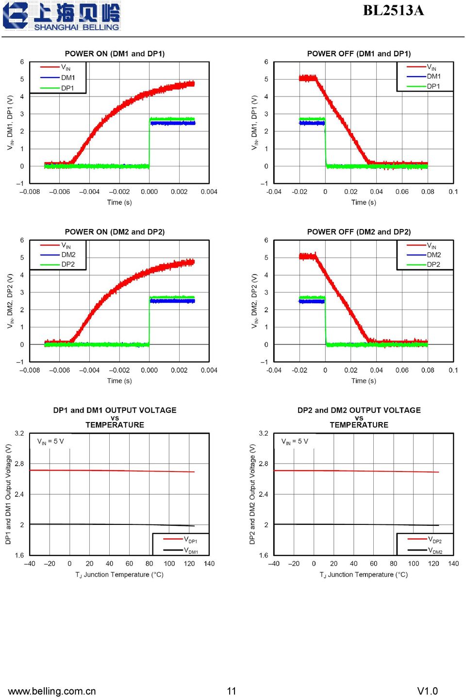
8 The BL2513A is USB dedicated charging port (DCP) controllers. Applications include vehicle power charger, wall adapters with USB DCP and other USB chargers. The BL2513A controllers has the auto-detect feature that monitors the D+ and D line voltages of the USB connector, providing the correct electrical signatures on the DP and DM pins for the correct detections of compliant portable devices to fast charge. These portable devices include smart phones, 5-V tablets and personal media players. DCP Auto-Detect The BL2513A integrate an auto-detect feature to support divider mode, short mode and 1.2V / 1.2Vmodes. If a divider device is attached, 2.7V is applied to the DP pin and 2.7V is applied to the DM pin. Fig 3. DCP Auto-Detect Functional Diagram Undervoltage Lockout (UVLO) The undervoltage lockout (UVLO) circuit disables DP1and DM1 output voltage until the input voltage reaches the UVLO turn-on threshold. Built-in hysteresis prevents unwanted oscillations due to input voltage drop from large current surges. The BL2513A only provide the correct electrical signatures on the data line of USB charger portand do not provide any power for the VBUS. Divide Mode Selection of 5-W and 10-W USB Chargers The BL2513A provide one type of connections between the DP pin and the DM pin and between the D+ data line and the D data line of the USB connector for a 12-W 8 V1.0

9 USB charger Table2 Charging Scheme for 12-W USB Chargers USB Charger Type Containing Charging Schemes 12-W Divider 3 2.7V on both D+ and D- Lines BC1.2DCP Fig w USB Charge Application Layout Guidelines Place the BL2513A near the USB output connector and place the 0.1-µF bypass capacitor near the IN pin. APPLICATION CIRCUIT 9 V1.0

10 CHARACTERISTICS CURVES 10 V1.0
11 11 V1.0
12 OUTLINE DRAWING SOT-23-6 Unit: mm 12 V1.0

VP223 USB Type-C DFP CC Controller with Universal Battery Charging
 Product Preliminary VP223 USB Type-C DFP CC Controller with Universal Battery Charging Mar. 11, 2015 VIA Labs, Inc. www.via-labs.com 7F, 529-1, Zhongzheng Rd., Xindian District, New Taipei City 231 Taiwan
AAT3520/2/4 MicroPower Microprocessor Reset Circuit
 General Description Features PowerManager The AAT3520 series of PowerManager products is part of AnalogicTech's Total Power Management IC (TPMIC ) product family. These microprocessor reset circuits are
LM2704 Micropower Step-up DC/DC Converter with 550mA Peak Current Limit
 Micropower Step-up DC/DC Converter with 550mA Peak Current Limit General Description The LM2704 is a micropower step-up DC/DC in a small 5-lead SOT-23 package. A current limited, fixed off-time control
STCC2540. USB charging controller with integrated power switch. Applications. Description. Features
 USB charging controller with integrated power switch Applications Datasheet - production data Features VFQFPN 16L 3 x 3 x 0.8 mm Compliant with USB charging specifications BC1.2, USB 2.0 and USB 3.0 standards
SC728/SC729. 2A Low Vin, Very Low Ron Load Switch. POWER MANAGEMENT Features. Description. Applications. Typical Application Circuit SC728 / SC729
 POWER MANAGEMT Features Input Voltage Range 1.1V to 2A Continuous Output Current Ultra-Low Ron 36mΩ Automatic Output Discharge Circuit Fast Turn-on Option With No Output Discharge Circuit SC728 Extended
Push-Pull FET Driver with Integrated Oscillator and Clock Output
 19-3662; Rev 1; 5/7 Push-Pull FET Driver with Integrated Oscillator General Description The is a +4.5V to +15V push-pull, current-fed topology driver subsystem with an integrated oscillator for use in
FAN5346 Series Boost LED Driver with PWM Dimming Interface
 FAN5346 Series Boost LED Driver with PWM Dimming Interface Features Asynchronous Boost Converter Drives LEDs in Series: FAN5346S20X: 20V Output FAN5346S30X: 30V Output 2.5V to 5.5V Input Voltage Range
STLQ015. 150 ma, ultra low quiescent current linear voltage regulator. Description. Features. Application
 150 ma, ultra low quiescent current linear voltage regulator Description Datasheet - production data Features SOT23-5L Input voltage from 1.5 to 5.5 V Very low quiescent current: 1.0 µa (typ.) at no load
1.5A Ultra Low Dropout Linear Regulator TJ3965
 FEATURES Ultra Low Dropout Voltage Low Ground Pin Current Excellent Line and Load Regulation Guaranteed Output Current of 1.5A Available in MSOP8, SOP8, SOP8PP, SOT223, TO252, TO263, TO220, and SOT89 Packages
5.5 V Input, 300 ma, Low Quiescent Current, CMOS Linear Regulator ADP122/ADP123
 Data Sheet 5.5 V Input, 3 ma, Low Quiescent Current, CMOS Linear Regulator ADP/ADP3 FEATURES Input voltage supply range:.3 V to 5.5 V 3 ma maximum output current Fixed and adjustable output voltage versions
CE8301 Series. Introduction. Features. Ordering Information. Applications SMALL PACKAGE PFM CONTROL STEP-UP DC/DC CONVERTER
 SMALL PACKAGE PFM CONTROL STEP-UP DC/DC CONVERTER Introduction The is a CMOS PFM-control step-up switching DC/DC converter that mainly consists of a reference voltage source, an oscillator, and a comparator.
Advanced Monolithic Systems
 Advanced Monolithic Systems FEATURES Three Terminal Adjustable or Fixed oltages* 1.5, 1.8, 2.5, 2.85, 3.3 and 5. Output Current of 1A Operates Down to 1 Dropout Line Regulation:.2% Max. Load Regulation:.4%
400KHz 60V 4A Switching Current Boost / Buck-Boost / Inverting DC/DC Converter
 Features Wide 5V to 32V Input Voltage Range Positive or Negative Output Voltage Programming with a Single Feedback Pin Current Mode Control Provides Excellent Transient Response 1.25V reference adjustable
AP331A XX G - 7. Lead Free G : Green. Packaging (Note 2)
") Features General Description Wide supply Voltage range: 2.0V to 36V Single or dual supplies: ±1.0V to ±18V Very low supply current drain (0.4mA) independent of supply voltage Low input biasing current:
Features General Description Wide supply Voltage range: 2.0V to 36V Single or dual supplies: ±1.0V to ±18V Very low supply current drain (0.4mA) independent of supply voltage Low input biasing current:
AAT4280 Slew Rate Controlled Load Switch
 General Description Features SmartSwitch The AAT4280 SmartSwitch is a P-channel MOSFET power switch designed for high-side load switching applications. The P-channel MOSFET device has a typical R DS(ON)
LDS8720. 184 WLED Matrix Driver with Boost Converter FEATURES APPLICATION DESCRIPTION TYPICAL APPLICATION CIRCUIT
 184 WLED Matrix Driver with Boost Converter FEATURES High efficiency boost converter with the input voltage range from 2.7 to 5.5 V No external Schottky Required (Internal synchronous rectifier) 250 mv
Features. V PP IN V CC3 IN V CC5 IN (opt) EN0 EN1 MIC2562
 EN0 EN1 MIC2562") MIC2562A /CardBus Socket Power Controller General Description The MIC2562A (Personal Computer Memory Card International Association) and CardBus power controller handles all PC Card slot power supply pins,
MIC2562A /CardBus Socket Power Controller General Description The MIC2562A (Personal Computer Memory Card International Association) and CardBus power controller handles all PC Card slot power supply pins,
ICL232. +5V Powered, Dual RS-232 Transmitter/Receiver. Description. Features. Ordering Information. Applications. Functional Diagram.
 ICL August V Powered, Dual RS Transmitter/Receiver Features Meets All RSC and V. Specifications Requires Only Single V Power Supply Onboard Voltage Doubler/Inverter Low Power Consumption Drivers ±V Output
1.5A ASYNCHRONOUS DC-DC BUCK CONV
 General Description The is a 1.4MHz fixed frequency, current mode, PWM buck (step-down) DC-DC converter, capable of driving a 1.5A load with high efficiency, excellent line and load regulation. The device
28 V, 56 m, Load Switch with Programmable Current Limit and Slew Rate Control
 28 V, 56 m, Load Switch with Programmable Current Limit and Slew Rate Control OPERATION DESCRIPTION SiP32419 and SiP32429 are load switches that integrate multiple control features that simplify the design
TSM2N7002K 60V N-Channel MOSFET
 SOT-23 SOT-323 Pin Definition: 1. Gate 2. Source 3. Drain PRODUCT SUMMARY V DS (V) R DS(on) (Ω) I D (ma) 5 @ V GS = 10V 100 60 5.5 @ V GS = 5V 100 Features Low On-Resistance ESD Protection High Speed Switching
TRIPLE PLL FIELD PROG. SPREAD SPECTRUM CLOCK SYNTHESIZER. Features
 DATASHEET ICS280 Description The ICS280 field programmable spread spectrum clock synthesizer generates up to four high-quality, high-frequency clock outputs including multiple reference clocks from a low-frequency
Cold-Junction-Compensated K-Thermocoupleto-Digital Converter (0 C to +1024 C)
") 19-2235; Rev 1; 3/02 Cold-Junction-Compensated K-Thermocoupleto-Digital General Description The performs cold-junction compensation and digitizes the signal from a type-k thermocouple. The data is output
19-2235; Rev 1; 3/02 Cold-Junction-Compensated K-Thermocoupleto-Digital General Description The performs cold-junction compensation and digitizes the signal from a type-k thermocouple. The data is output
MC33064DM 5 UNDERVOLTAGE SENSING CIRCUIT
 Order this document by MC3464/D The MC3464 is an undervoltage sensing circuit specifically designed for use as a reset controller in microprocessor-based systems. It offers the designer an economical solution
INTEGRATED CIRCUITS DATA SHEET. TDA7000 FM radio circuit. Product specification File under Integrated Circuits, IC01
 INTEGRATED CIRCUITS DATA SHEET File under Integrated Circuits, IC01 May 1992 GENERAL DESCRIPTION The is a monolithic integrated circuit for mono FM portable radios, where a minimum on peripheral components
UC3842/UC3843/UC3844/UC3845
 SMPS Controller www.fairchildsemi.com Features Low Start up Current Maximum Duty Clamp UVLO With Hysteresis Operating Frequency up to 500KHz Description The UC3842/UC3843/UC3844/UC3845 are fixed frequencycurrent-mode
PAM2804. Pin Assignments. Description. Applications. Features. Typical Applications Circuit 1A STEP-DOWN CONSTANT CURRENT, HIGH EFFICIENCY LED DRIVER
 1A STEP-DOWN CONSTANT CURRENT, HIGH EFFICIENCY LED DRIER Description Pin Assignments The is a step-down constant current LED driver. When the input voltage is down to lower than LED forward voltage, then
IR1168S DUAL SMART RECTIFIER DRIVER IC
 Datasheet No PD97382 September 26, 2011 IR1168S DUAL SMART RECTIFIER DRIVER IC Features Secondary-side high speed controller for synchronous rectification in resonant half bridge topologies 200V proprietary
FEATURES DESCRIPTIO APPLICATIO S. LTC4054-4.2/LTC4054X-4.2 Standalone Linear Li-Ion Battery Charger with Thermal Regulation in ThinSOT
 FEATURES Programmable Charge Current Up to 8mA No MOSFET, Sense Resistor or Blocking Diode Required Complete Linear Charger in ThinSOT TM Package for Single Cell Lithium-Ion Batteries Constant-Current/Constant-Voltage
High-Speed, 5 V, 0.1 F CMOS RS-232 Driver/Receivers ADM202/ADM203
 a FEATURES kb Transmission Rate ADM: Small (. F) Charge Pump Capacitors ADM3: No External Capacitors Required Single V Power Supply Meets EIA-3-E and V. Specifications Two Drivers and Two Receivers On-Board
LM2576R. 3.0A, 52kHz, Step-Down Switching Regulator FEATURES. Applications DESCRIPTION TO-220 PKG TO-220V PKG TO-263 PKG ORDERING INFORMATION
 LM2576 FEATURES 3.3, 5.0, 12, 15, and Adjustable Output ersions Adjustable ersion Output oltage Range, 1.23 to 37 +/- 4% AG10Maximum Over Line and Load Conditions Guaranteed 3.0A Output Current Wide Input
MP2259 1A, 16V, 1.4MHz Step-Down Converter
 MP59 1A, 1V, 1.MHz Step-Down Converter TM The Future of Analog IC Technology DESCRIPTION The MP59 is a monolithic integrated stepdown switch mode converter with an internal power MOSFET. It achieves 1A
AS2815. 1.5A Low Dropout Voltage Regulator Adjustable & Fixed Output, Fast Response
 1.5A Low Dropout oltage Regulator Adjustable & Fixed Output, Fast Response FEATURES Adjustable Output Down To 1.2 Fixed Output oltages 1.5, 2.5, 3.3, 5.0 Output Current of 1.5A Low Dropout oltage 1.1 Typ.
On/Off Controller with Debounce and
 19-4128; Rev ; 5/8 On/Off Controller with Debounce and General Description The is a pushbutton on/off controller with a single switch debouncer and built-in latch. It accepts a noisy input from a mechanical
DW8501 High Power LED Driver
 Descriptions The is an instant On/Off LED driver for high power LED applications. At output stage, one regulated current port is designed to provide a uniform and constant current sink for driving LEDs
STCC5011, STCC5021. USB charging controller with integrated power switch and attach detector. Applications. Features. Description
 USB charging controller with integrated power switch and attach detector Applications Datasheet - production data Features VFQFPN 16L - 3 x 3 x 0.8 mm Compliant with USB charging specifications BC1.2,
RT9515. Linear Single Cell Li-Ion Battery Charger IC. General Description. Features. Applications. Ordering Information RT9515. Pin Configurations
 Linear Single Cell Li-Ion Battery Charger IC General Description The RT515 is a fully integrated low cost single-cell Li- Ion battery charger IC ideal for portable applications. The RT515 is capable of
MIC33050. General Description. Features. Applications. Typical Application. 4MHz Internal Inductor PWM Buck Regulator with HyperLight Load
 4MHz Internal Inductor PWM Buck Regulator with HyperLight Load General Description The Micrel is a high-efficiency 600mA PWM synchronous buck (step-down) regulator with internal inductor featuring HyperLight
3-Channel Supervisor IC for Power Supply
 3-Channel Supervisor IC for Power Supply Features Over-voltage protection and lockout Under-voltage protection and lockout Open drain power good output signal Built-in 300mS delay for power good 38mS de-bounce
TS555. Low-power single CMOS timer. Description. Features. The TS555 is a single CMOS timer with very low consumption:
 Low-power single CMOS timer Description Datasheet - production data The TS555 is a single CMOS timer with very low consumption: Features SO8 (plastic micropackage) Pin connections (top view) (I cc(typ)
28V, 2A Buck Constant Current Switching Regulator for White LED
 28V, 2A Buck Constant Current Switching Regulator for White LED FP7102 General Description The FP7102 is a PWM control buck converter designed to provide a simple, high efficiency solution for driving
LM1117/LM1117I 800mA Low-Dropout Linear Regulator
 LM1117/LM1117I 800mA Low-Dropout Linear Regulator General Description The LM1117 is a series of low dropout voltage regulators with a dropout of 1.2 at 800mA of load current. It has the same pin-out as
SPREAD SPECTRUM CLOCK GENERATOR. Features
 DATASHEET ICS7152 Description The ICS7152-01, -02, -11, and -12 are clock generators for EMI (Electro Magnetic Interference) reduction (see below for frequency ranges and multiplier ratios). Spectral peaks
Supertex inc. HV256. 32-Channel High Voltage Amplifier Array HV256. Features. General Description. Applications. Typical Application Circuit
 32-Channel High Voltage Amplifier Array Features 32 independent high voltage amplifiers 3V operating voltage 295V output voltage 2.2V/µs typical output slew rate Adjustable output current source limit
LM380 Audio Power Amplifier
 LM380 Audio Power Amplifier General Description The LM380 is a power audio amplifier for consumer application. In order to hold system cost to a minimum, gain is internally fixed at 34 db. A unique input
LM3940 1A Low Dropout Regulator for 5V to 3.3V Conversion
 1A Low Dropout Regulator for 5V to 3.3V Conversion General Description The LM3940 is a 1A low dropout regulator designed to provide 3.3V from a 5V supply. The LM3940 is ideally suited for systems which
Spread-Spectrum Crystal Multiplier DS1080L. Features
 Rev 1; 3/0 Spread-Spectrum Crystal Multiplier General Description The is a low-jitter, crystal-based clock generator with an integrated phase-locked loop (PLL) to generate spread-spectrum clock outputs
Low Voltage, Resistor Programmable Thermostatic Switch AD22105
 a Low Voltage, Resistor Programmable Thermostatic Switch AD22105 FEATURES User-Programmable Temperature Setpoint 2.0 C Setpoint Accuracy 4.0 C Preset Hysteresis Wide Supply Range (+2.7 V dc to +7.0 V dc)
Constant Voltage and Constant Current Controller for Adaptors and Battery Chargers
 TECHNICAL DATA Constant Voltage and Constant Current Controller for Adaptors and Battery Chargers IK3051 Description IK3051 is a highly integrated solution for SMPS applications requiring constant voltage
INTEGRATED CIRCUITS. NE558 Quad timer. Product data Supersedes data of 2001 Aug 03. 2003 Feb 14
 INTEGRATED CIRCUITS Supersedes data of 2001 Aug 03 2003 Feb 14 DESCRIPTION The Quad Timers are monolithic timing devices which can be used to produce four independent timing functions. The output sinks
ST202 5V POWERED MULTI-CHANNEL RS-232 DRIVERS AND RECEIVERS
 5V POWERED MULTI-CHANNEL RS-232 DRIVERS AND RECEIVERS SUPPLY VOLTAGE RANGE: 4.5 TO 5.5V SUPPLY CURRENT NO LOAD (TYP): 1.5mA TRASMITTER OUTPUT VOLTAGE SWING (TYP): ± 9V TRANSITION SLEW RATE (TYP.): 12V/µs
STLM20. Ultra-low current 2.4 V precision analog temperature sensor. Features. Applications
 Ultra-low current 2.4 V precision analog temperature sensor Features Precision analog voltage output temperature sensor ±1.5 C maximum temperature accuracy at 25 C (±0.5 C typical) Ultra-low quiescent
ICS514 LOCO PLL CLOCK GENERATOR. Description. Features. Block Diagram DATASHEET
 DATASHEET ICS514 Description The ICS514 LOCO TM is the most cost effective way to generate a high-quality, high-frequency clock output from a 14.31818 MHz crystal or clock input. The name LOCO stands for
ICS650-44 SPREAD SPECTRUM CLOCK SYNTHESIZER. Description. Features. Block Diagram DATASHEET
 DATASHEET ICS650-44 Description The ICS650-44 is a spread spectrum clock synthesizer intended for video projector and digital TV applications. It generates three copies of an EMI optimized 50 MHz clock
LM2941/LM2941C 1A Low Dropout Adjustable Regulator
 LM2941/LM2941C 1A Low Dropout Adjustable Regulator General Description The LM2941 positive voltage regulator features the ability to source 1A of output current with a typical dropout voltage of 0.5V and
INDUSTRIAL VOLTAGE AMPLIFIER IC AM401 PRINCIPLE FUNCTION
 PINCIPLE FUNCTION Amplification and conversion of differential signals referenced to ground to adjustable industrial voltages (0...Vcc-5V, e.g. 0...5/10V etc.) Variable current/voltage source and integrated
CMOS Switched-Capacitor Voltage Converters ADM660/ADM8660
 CMOS Switched-Capacitor Voltage Converters ADM66/ADM866 FEATURES ADM66: Inverts or Doubles Input Supply Voltage ADM866: Inverts Input Supply Voltage ma Output Current Shutdown Function (ADM866) 2.2 F or
PI5USB2544. USB Charging Port Controller and Detection Power Switch. Description. Features. Applications. Pin Configuration (TQFN-16L, ZH)
") Features Description Supports CDP/DCP Modes per USB Battery Charging Specification 1.2 Supports Shorted Mode per Chinese Telecommunication Industry Standard YD/T1591-2009 Supports non-bc1.2 Charging Modes
Features Description Supports CDP/DCP Modes per USB Battery Charging Specification 1.2 Supports Shorted Mode per Chinese Telecommunication Industry Standard YD/T1591-2009 Supports non-bc1.2 Charging Modes
SG2525A SG3525A REGULATING PULSE WIDTH MODULATORS
 SG2525A SG3525A REGULATING PULSE WIDTH MODULATORS 8 TO 35 V OPERATION 5.1 V REFERENCE TRIMMED TO ± 1 % 100 Hz TO 500 KHz OSCILLATOR RANGE SEPARATE OSCILLATOR SYNC TERMINAL ADJUSTABLE DEADTIME CONTROL INTERNAL
Enpirion Power Datasheet EP53F8QI 1500 ma PowerSoC Voltage Mode Synchronous PWM Buck with Integrated Inductor
 Enpirion Power Datasheet EP53F8QI 1500 ma PowerSoC Voltage Mode Synchronous PWM Buck with Integrated Inductor Description The EP53F8QI provides high efficiency in a very small footprint. Featuring integrated
Features. Modulation Frequency (khz) VDD. PLL Clock Synthesizer with Spread Spectrum Circuitry GND
 VDD. PLL Clock Synthesizer with Spread Spectrum Circuitry GND") DATASHEET IDT5P50901/2/3/4 Description The IDT5P50901/2/3/4 is a family of 1.8V low power, spread spectrum clock generators capable of reducing EMI radiation from an input clock. Spread spectrum technique
DATASHEET IDT5P50901/2/3/4 Description The IDT5P50901/2/3/4 is a family of 1.8V low power, spread spectrum clock generators capable of reducing EMI radiation from an input clock. Spread spectrum technique
24-Channel Automotive Switch Monitor
 9-4464; Rev ; 2/9 EVALUATION KIT AVAILABLE 24-Channel Automotive Switch Monitor General Description The is a 24-channel automotive contact monitor designed as an interface between mechanical switches and
AP1506. 150KHz, 3A PWM BUCK DC/DC CONVERTER. Pin Assignments. Description. Features. Applications. ( Top View ) 5 SD 4 FB 3 Gnd 2 Output 1 V IN
 5 SD 4 FB 3 Gnd 2 Output 1 V IN") Description Pin Assignments The series are monolithic IC designed for a stepdown DC/DC converter, and own the ability of driving a 3A load without external transistor. Due to reducing the number of external
Description Pin Assignments The series are monolithic IC designed for a stepdown DC/DC converter, and own the ability of driving a 3A load without external transistor. Due to reducing the number of external
FEATURES DESCRIPTION APPLICATIONS BLOCK DIAGRAM. PT2248 Infrared Remote Control Transmitter
 Infrared Remote Control Transmitter DESCRIPTION PT2248 is an infrared remote control transmitter utilizing CMOS Technology. It is capable of 18 functions and a total of 75 commands. Single-shot and continuous
INTEGRATED CIRCUITS DATA SHEET. TDA7052 1 W BTL mono audio amplifier. Product specification File under Integrated Circuits, IC01
 INTEGRATED CIRCUITS DATA SHEET TDA7052 1 W BTL mono audio amplifier File under Integrated Circuits, IC01 July 1994 GENERAL DESCRIPTION The TDA7052 is a mono output amplifier in a 8-lead dual-in-line (DIL)
MIC33030. General Description. Features. Applications. Typical Application. 8MHz 400mA Internal Inductor Buck Regulator with HyperLight Load
 8MHz 400mA Internal Inductor Buck Regulator with HyperLight Load General Description The is a high-efficiency, 8MHz, 400mA synchronous buck regulator with an internal inductor and HyperLight Load mode.
1.0A LOW DROPOUT LINEAR REGULATOR
 1.0A LOW DROPOUT LINEAR REGULATOR Description Pin Assignments The is a low dropout three-terminal regulator with 1.0A output current ability, and the dropout voltage is specified at typical 1.1V at 1.0A
HT9170 DTMF Receiver. Features. General Description. Selection Table
 DTMF Receiver Features Operating voltage: 2.5V~5.5V Minimal external components No external filter is required Low standby current (on power down mode) General Description The HT9170 series are Dual Tone
TDA2004R. 10 + 10 W stereo amplifier for car radio. Features. Description
 10 + 10 W stereo amplifier for car radio Features Low distortion Low noise Protection against: Output AC short circuit to ground Overrating chip temperature Load dump voltage surge Fortuitous open ground
WHITE LED STEP-UP CONVERTER. Features
 General Description The is an inductor-based DC/DC converter designed to drive up to eight white LEDs in series for backlight. Only one feedback resistor is needed to control the LED current and obtain
SG6516 PC Power Supply Supervisors
 SG6516 PC Power Supply Supervisors Features Two 12V Sense Input Pins: VS12 and VS12B Over-Voltage Protection (OVP) for 3.3V, 5V, and two 12V Over-Current Protection (OCP) for 3.3V, 5V, and two 12V Under-Voltage
Silvertel. Ag5200. 1 Features. 2 Description. Power-over-Ethernet Plus Module. IEEE802.3at and IEEE802.3af compliant. Maximum 30W output power
 Silvertel V1.1 November 2012 Datasheet Pb 1 Features IEEE802.3at and IEEE802.3af compliant Maximum 30W output power Dual In-Line (DIL) package size 50.6mm (L) x 30mm (W) Overload, short-circuit and thermal
ICS379. Quad PLL with VCXO Quick Turn Clock. Description. Features. Block Diagram
 Quad PLL with VCXO Quick Turn Clock Description The ICS379 QTClock TM generates up to 9 high quality, high frequency clock outputs including a reference from a low frequency pullable crystal. It is designed
High Accuracy, Ultralow IQ, 1 A, anycap Low Dropout Regulator ADP3338
 High Accuracy, Ultralow IQ, 1 A, anycap Low Dropout Regulator ADP3338 FEATURES High accuracy over line and load: ±.8% @ 25 C, ±1.4% over temperature Ultralow dropout voltage: 19 mv (typ) @ 1 A Requires
LM217M, LM317M. Medium current 1.2 to 37 V adjustable voltage regulator. Description. Features
 Medium current 1.2 to 37 V adjustable voltage regulator Datasheet - production data Description The LM217M and LM317M are monolithic integrated circuits in DPAK package used as positive adjustable voltage
DATA SHEET. TDA8560Q 2 40 W/2 Ω stereo BTL car radio power amplifier with diagnostic facility INTEGRATED CIRCUITS. 1996 Jan 08
 INTEGRATED CIRCUITS DATA SHEET power amplifier with diagnostic facility Supersedes data of March 1994 File under Integrated Circuits, IC01 1996 Jan 08 FEATURES Requires very few external components High
VITESSE SEMICONDUCTOR CORPORATION. 16:1 Multiplexer. Timing Generator. CMU x16
 Features 16:1 2.488 Gb/s Multiplexer Integrated PLL for Clock Generation - No External Components 16-bit Wide, Single-ended, ECL 100K Compatible Parallel Data Interface 155.52 MHz Reference Clock Frequency
TYPICAL APPLICATION CIRCUIT. ORDER INFORMATION SOP-EP 8 pin A703EFT (Lead Free) A703EGT (Green)
 A703EGT (Green)") www.addmtek.com 2 CHANNELS 150mA HIGH VOLTAGE ADJUSTABLE CURRENT REGULATOR DESCRIPTION A703 is a high voltage, adjustable constant current driver for LED applications. Two regulated current ports are designed
www.addmtek.com 2 CHANNELS 150mA HIGH VOLTAGE ADJUSTABLE CURRENT REGULATOR DESCRIPTION A703 is a high voltage, adjustable constant current driver for LED applications. Two regulated current ports are designed
5A LOW DROPOUT LINEAR REGULATOR General Description. Features. Applications
 General Description The is a series of low dropout positive voltage regulators with a maximum dropout of.5v at 5A of load current. The series features on-chip thermal limiting which provides protection
Features. Ordering Information. * Underbar marking may not be to scale. Part Identification
 MIC86 Teeny Ultra Low Power Op Amp General Description The MIC86 is a rail-to-rail output, input common-mode to ground, operational amplifier in Teeny SC7 packaging. The MIC86 provides 4kHz gain-bandwidth
Product Datasheet P1110 915 MHz RF Powerharvester Receiver
 DESCRIPTION The Powercast P1110 Powerharvester receiver is an RF energy harvesting device that converts RF to DC. Housed in a compact SMD package, the P1110 receiver provides RF energy harvesting and power
LD7550-B. Green-Mode PWM Controller. General Description. Features. Applications. Typical Application. REV: 01a 12/22/2006 LD7550-B
 12/22/2006 REV: 01a Green-Mode PWM Controller General Description The LD7550-B is a low cost, low startup current, current mode PWM controller with green-mode power-saving operation. The integrated functions
VS-500 Voltage Controlled SAW Oscillator
 VS-500 Voltage Controlled SAW Oscillator Features Improved High Performance ASIC Industry Standard Package, 9 x 14 x 4.5 mm Frequencies from 155 MHz to 850 MHz 3.3 V or 5.0 V Operation At 155.52 MHz, Jitter
Features: High reliability. Very sharp reverse characteristic. Zener voltage 3.3V to 12V. V z -tolerance ±5%.
 Features: High reliability. Very sharp reverse characteristic. Zener voltage 3.3V to 12V. V z -tolerance ±5%. Applications: Voltage stabilization. Absolute Maximum Ratings Parameter Test Conditions Symbol
SP490/491 Full Duplex RS-485 Transceivers
 SP490/491 Full Duplex RS-485 Transceivers FEATURES +5V Only Low Power BiCMOS Driver/Receiver Enable (SP491) RS-485 and RS-422 Drivers/Receivers Pin Compatible with LTC490 and SN75179 (SP490) Pin Compatible
LM56 Dual Output Low Power Thermostat
 Dual Output Low Power Thermostat General Description The LM56 is a precision low power thermostat. Two stable temperature trip points (V T1 and V T2 ) are generated by dividing down the LM56 1.250V bandgap
Features INVERTING. 0.6mA NONINVERTING INVERTING. 0.6mA NONINVERTING
 MIC442/442/4428 Dual 1.A-Peak Low-Side MOSFET Driver General Description The MIC442/442/4428 family are highly-reliable dual lowside MOSFET drivers fabricated on a BiCMOS/DMOS process for low power consumption
MAX1501 Highly Integrated, Linear Battery Charger with Thermal Regulation for Portable Applications
 General Description The MAX1501 intelligent, constant-current, constantvoltage (CCCV), temperature-regulated battery charger charges a single lithium-ion (Li+) cell or three-cell NiMH/NiCd batteries. The
40 V, 200 ma NPN switching transistor
 Rev. 01 21 July 2009 Product data sheet BOTTOM VIEW 1. Product profile 1.1 General description NPN single switching transistor in a SOT883 (SC-101) leadless ultra small Surface-Mounted Device (SMD) plastic
1.5A Very L.D.O Voltage Regulator LM29150/29151/29152
 FEATURES High Current Capability 1.5A Low Dropout Voltage 350mV Low Ground Current Accurate 1% Guaranteed Initial Tolerance Extremely Fast Transient Response Reverse-Battery and "Load Dump" Protection
Features. Applications
 Pb Lead-Free 1A LOW DROPOUT LINEAR REGULATOR Description The is a series of low dropout three-terminal regulators with a dropout of 1.15V at 1A output current. The series provides current limiting and
STF201-22 & STF201-30
 Description The STF201 is a combination EMI filter and line termination device with integrated TVS diodes for use on downstream USB ports. It is constructed using a proprietary technology that allows passive
Hardware Documentation. Data Sheet HAL 202. Hall-Effect Sensor. Edition Sept. 18, 2014 DSH000159_002EN
 Hardware Documentation Data Sheet HAL 202 Hall-Effect Sensor Edition Sept. 18, 2014 DSH000159_002EN HAL202 Copyright, Warranty, and Limitation of Liability The information and data contained in this document
Tone Ringer SL2410 LOGIC DIAGRAM PIN ASSIGNMENT SLS
 Tone Ringer The SL2410 is a bipolar integrated circuit designed for telephone bell replacement. Designed for Telephone Bell Replacement Low Curent Drain Adjustable 2-frequency Tone Adjustable Warbling
MAX14760/MAX14762/MAX14764 Above- and Below-the-Rails Low-Leakage Analog Switches
 19-652; Rev 1; 8/12 EVALUATION KIT AVAILABLE MAX1476// General Description The MAX1476// analog switches are capable of passing bipolar signals that are beyond their supply rails. These devices operate
TDA2822 DUAL POWER AMPLIFIER SUPPLY VOLTAGE DOWN TO 3 V LOW CROSSOVER DISTORSION LOW QUIESCENT CURRENT BRIDGE OR STEREO CONFIGURATION
 TDA2822 DUAL POER AMPLIFIER SUPPLY VOLTAGE DON TO 3 V. LO CROSSOVER DISTORSION LO QUIESCENT CURRENT BRIDGE OR STEREO CONFIGURATION DESCRIPTION The TDA2822 is a monolithic integrated circuit in 12+2+2 powerdip,
Silvertel. Ag9800M. 1. Features. 2. Description. Miniature PoE Module. Small SMT package. IEEE802.3af compliant. Low cost
 Silvertel V1.2 December 2014 Datasheet Ag9800M Miniature PoE Module Pb 1. Features Small SMT package IEEE802.3af compliant Low cost Input voltage range 36V to 57V Minimal external components required Short-circuit
MOSFET N-channel enhancement switching transistor IMPORTANT NOTICE. http://www.philips.semiconductors.com use http://www.nxp.com
 Rev. 3 21 November 27 Product data sheet Dear customer, IMPORTANT NOTICE As from October 1st, 26 Philips Semiconductors has a new trade name - NXP Semiconductors, which will be used in future data sheets
Precision, Unity-Gain Differential Amplifier AMP03
 a FEATURES High CMRR: db Typ Low Nonlinearity:.% Max Low Distortion:.% Typ Wide Bandwidth: MHz Typ Fast Slew Rate: 9.5 V/ s Typ Fast Settling (.%): s Typ Low Cost APPLICATIONS Summing Amplifiers Instrumentation
MIC4451/4452. General Description. Features. Applications. Functional Diagram V S. 12A-Peak Low-Side MOSFET Driver. Bipolar/CMOS/DMOS Process
 12A-Peak Low-Side MOSFET Driver Bipolar/CMOS/DMOS Process General Description MIC4451 and MIC4452 CMOS MOSFET drivers are robust, efficient, and easy to use. The MIC4451 is an inverting driver, while the