PREMIUM CLEAN ROOM MONITOR MODELS 8630-CRM-S 8630-CRM-P
|
|
|
- Randolf Jones
- 8 years ago
- Views:
Transcription
1 PREMIUM CLEAN ROOM MONITOR MODELS 8630-CRM-S 8630-CRM-P MANUAL SUPPLEMENT Contents of this manual supplement include: Sequence of Operation Menu Structure Description of New Software Items Deleted Software Menu Items Wiring Diagrams Access Codes Sequence of Operation The Model 8630-CRM monitors room pressure by utilizing a through-the-wall pressure sensor. The Model 8630-CRM features high and low pressure alarms for up to two independent sensors. A minimum supply volume alarm is also present. Additionally, the Model 8630-CRM supports the open MODBUS protocol over an RS-485 network and an analog pressure output.

2 Menu Structure ALARM CONFIGURE CALIBRATION LOW ALARM HIGH ALARM SEC LOW ALM SEC HIGH ALM MIN SUP ALM ALARM RESET AUDIBLE ALM ALARM DELAY MUTE TIMEOUT DISPLAY AVG UNITS ROOM VOLUME 2 SENSOR SENSOR ZERO SENSOR SPAN 2SENSOR ZERO 2SENSOR SPAN SUP 1 ZERO SUP 2 ZERO ELEVATION INTERFACE DIAGNOSTICS PRESSURE FLOW NET PROTOCOL NET ADDRESS OUT SIG PRESS AOUT SENSOR INPUT SENSOR STAT 2 SENS INPUT 2 SENS STAT SUP 1 INPUT SUP 2 INPUT PRES ALM REL SUP ALM REL SENSOR TYPE MAX OUT SIG MAX OUT VAL SUP1 AREA SUP2 AREA SUP1 KFACTOR SUP2 KFACTOR SENSOR TYPE MAX OUT SIG MAX OUT VAL Figure 1: Menu Items - Model 8630-CRM Premium Monitor -2-

3 Description of New Software Items The Model 8630-CRM has additional software items. Alarm Menu Menu Item LOW ALARM SEC LOW ALM HIGH ALARM SEC HIGH ALM Calibration Menu Menu Item SUP 1 ZERO SUP 2 ZERO Description The LOW ALARM and SEC LOW ALARM items set the low pressure alarm set points for the primary and secondary pressure sensor. A low alarm condition occurs when the room pressure falls below or goes in the opposite direction of the low alarm set point. The SEC LOW ALM setpoint is only used when the second sensor is enabled through the CONFIGURE menu. The LOW ALARM and SEC LOW ALM can be set to OFF. The LOW ALARM and SEC LOW ALM have a range from 0 to within H 2 O of the pressure SETPOINT. For TSI or BI DIRECT sensor types, the low alarm must be of the same sign (positive or negative) as the pressure SETPOINT. The default value is OFF. The HIGH ALARM and SEC HIGH ALM items set the high pressure alarm set points. A high alarm condition occurs when the room pressure rises above the high alarm set point. The SEC HIGH ALM setpoint is only used when the second sensor is enabled through the CONFIGURE menu. The HIGH ALARM and SEC HIGH ALM can be set to OFF. The HIGH ALARM and SEC HIGH ALM have a range from within H 2 O of the pressure SETPOINT to within H 2 O of the pressure MAX OUT VAL. For TSI or BI DIRECT sensor types, the high alarm must be of the same sign (positive or negative) as the pressure SETPOINT. The default value is OFF. Description The SUP 1 ZERO and SUP 2 ZERO items are used to calibrate the flow station pressure transducers. A zero or no flow setpoint needs to be established prior to using the supply flow measurements (see Calibration section of manual following menu item listing). -3-

4 Diagnostics Menu Menu Item PRESS AOUT SUP 1 INPUT SUP 2 INPUT PRES ALM REL SUP ALM REL Description The PRESS AOUT item is used to vary the analog output from the Model 8630-CRM. When this item is entered, a number will be shown on the display indicating the last analog output value. The value displayed ranges from 0 to 255. The value 255 corresponds to the lowest voltage (current) output and 0 corresponds to the highest voltage (current) output. Pressing the key will decrease the analog output and increase the value displayed. Pressing the key will increase the analog output and decrease the value displayed. The PRESS AOUT function can be used in conjunction with a voltmeter to verify that the analog output is correct. The SUP 1 INPUT and SUP 2 INPUT items are used to read the flow measurement inputs directly. When these items are entered, the display will indicate the voltage from the proper transducer. The exact voltage displayed is relatively unimportant. It is more important that the voltage changes to indicate the flow station is working properly. The PRES ALM REL item is used to change the state of the pressure alarm relay. When this item is entered, the display will indicate either OPEN or CLOSED. The / keys are used to toggle the state of the relay. The key is used to OPEN the alarm contact. The key is used to CLOSE the alarm contact. When the contact is closed, the pressure alarm relay should be in an alarm condition. The SUP ALM REL item is used to change the state of the minimum supply alarm relay. When this item is entered, the display will indicate either OPEN or CLOSED. The / keys are used to toggle the state of the relay. The key is used to OPEN the alarm contact. The key is used to CLOSE the alarm contact. When the contact is closed, the minimum supply alarm relay should be in an alarm condition. -4-

5 Pressure Menu Menu Item SENSOR TYPE MAX OUT SIG MAX OUT VAL Description The SENSOR TYPE item is used to set the type of pressure sensor used to measure the room pressure differential. This item can be set to TSI, UNI DIRECT, or BI DIRECT. The default value is TSI. The MAX OUT SIG item is used to set the maximum pressure output voltage from the transducer used. This item can be set to 5 V or 10 V, with a default value of 10 V. For a TSI pressure sensor, the MAX OUT SIG must be set to 10 V. The MAX OUT VAL item is used to set the maximum pressure reading of the transducer used. This item can be set between 0.1 H2O and 2 H2O, with a default value of 0.2 H2O. For a TSI pressure sensor, the MAX OUT VAL must be set to 0.2 H2O. For a UNI DIRECT pressure sensor, the MAX OUT VAL must be programmed as a positive or negative, depending on the pressure relationship of the space to its reference. For UNI DIRECT sensors, 0 V (or 4 ma in CURRENT mode) corresponds to a pressure differential of 0, and 10 V or (20 ma in CURRENT mode) corresponds to a pressure differential of MAX OUT VAL. For BI DIRECT or TSI sensors, 0 V (or 4 ma in CURRENT mode) corresponds to a pressure differential of -MAX OUT VAL, and 10 V or (20 ma in CURRENT mode) corresponds to a pressure differential of MAX OUT VAL. -5-

6 Flow Menu Menu Item SUP1 AREA SUP2 AREA SUP1 KFACTOR SUP2 KFACTOR SENSOR TYPE MAX OUT SIG MAX OUT VAL Description The SUP1 AREA and SUP2 AREA items are used to input the duct sizes for the first and second supply. The duct sizes are needed to compute the air flowing into the room. These items require a flow sensor to be mounted in the proper supply duct. When a duct area is programmed, the display will automatically scroll the actual total supply flow as part of the display scroll sequence. If a zero value is entered, the supply flow value will not scroll on the display. The programmed duct areas can range from 0 to 10 square feet if the PresSura monitor displays English units. If the PresSura monitor displays metric units, then the duct areas can range from 0 to square meters. The default is 0. The KFACTOR menu item sets the K factor for the flow probe being used. The flow signal is multiplied by the KFACTOR so that the flow measurement matches the actual flow, usually determined with a pitot tube traverse. The KFACTOR has a minimum value of 0 and a maximum value of 10., with a default of 1. The SENSOR TYPE item is used to select the flow station input signal. PRESSURE is used when flow stations with pressure transducers are installed. LINEAR is selected when a linear output flow station, typically a thermal-based flow station, is installed. The MAX OUT SIG item is used to set the maximum output voltage from the transducer used. This item can be set to 5 V or 10 V, with a default value of 5 V. For a TSI flow station, the MAX OUT SIG must be set to 5 V. The MAX OUT VAL item is used to set the maximum pressure reading of the transducer used, or the maximum velocity of the linear flow station used. For a pressure based measurement, this item can be set between 0.1 H 2 O and 0.5 H 2 O, with a default value of 0.5 H 2 O. For a linear flow station, this item can be set between 0 and 5,000 ft/min. For a TSI flow station, the MAX OUT VAL must be set to 0.5 H 2 O. -6-

7 Deleted Software Menu Items The following items have been replaced on the 8630-CRM. ALARM MENU CONFIGURE MENU CALIBRATION MENU INTERFACE MENU DIAGNOSTICS MENU NEG LOW ALARM NEG HIGH ALARM POS LOW ALARM POS HIGH ALARM MIN CFM ALM 2 LOW ALM 2 HIGH ALM ROOM MODE DCT AREA FLOW ZERO OUTPUT RANGE ANALOG OUT KEY INPUT FLOW INPUT LOW ALM RELAY HIGH ALM RELAY -7-

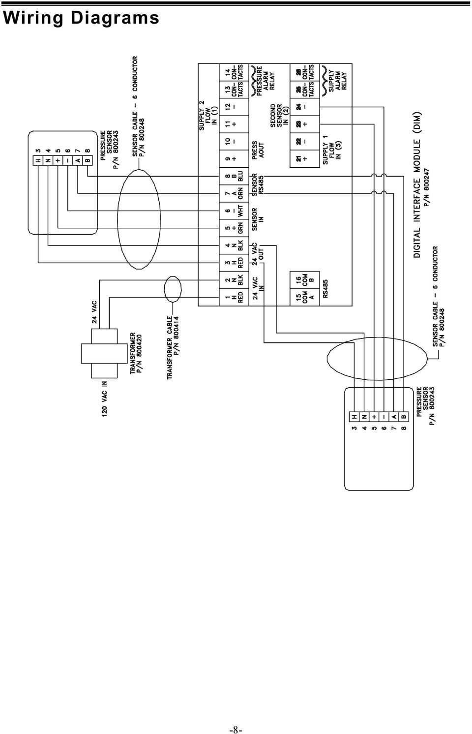
8 Wiring Diagrams -8-
9 -9-

10 Access Codes The 8630-CRM has a single access code for all menus. Each menu has the access code enabled individually; implementing the access code in one menu does not enable the access code in other menus. When an access code is required, pressing the following key sequence will provide access: Key # 1 EMERGENCY 2 MUTE 3 MUTE 4 MENU 5 AUX TSI Incorporated Visit our website for more information. USA Tel: UK Tel: France Tel: Germany Tel: India Tel: China Tel: Singapore Tel: CRM-S/-P Rev. C (7/20/2012) 2012 TSI Incorporated Printed in U.S.A.

PRESSURA CLEAN ROOM PRESSURE MONITOR/CONTROLLER W/LON/BACNET
 PRESSURA CLEAN ROOM PRESSURE MONITOR/CONTROLLER W/LON/BACNET MODELS 8631-CRM/8631-CRM-BAC/ 8631-CRC/8631-CRC-BAC OPERATION AND SERVICE MANUAL PRESSURA CLEAN ROOM PRESSURE MONITOR/CONTROLLER W/LON/BACNET
How To Control A Pressura Room Pressure Monitor
 PRESSURA ROOM PRESSURE MONITOR MODELS 8631-HM/8631-HM-BAC PRESSURA ROOM PRESSURE CONTROLLER MODELS 8631-HC/8631-HC-BAC W/LON/BACNET OPERATION AND SERVICE MANUAL PRESSURA ROOM PRESSURE MONITOR MODELS 8631-HM/8631-HM-BAC
CONTAMINATION CONTROL FOR ELECTRONIC AND SEMICONDUCTOR APPLICATIONS
 CONTAMINATION CONTROL FOR ELECTRONIC AND SEMICONDUCTOR APPLICATIONS UNDERSTANDING, ACCELERATED TSI SETS THE STANDARD FOR PARTICLE COUNTING Performance Semiconductor, hard disk drive, and flat panel manufacturers
SLIM LINE FUME HOOD MONITOR
 SLIM LINE FUME HOOD MONITOR Phoenix Controls FHM420 Fume Hood Monitor is sized to fit any fume hood and includes icons for simple and universal operation. The FHM420 slim line monitor works in conjunction
TEMON 8-C. Doc. N MO-0370-ING TEMPERATURE MONITOR DEVICE TYPE TEMON 8-C OPERATION MANUAL. Microener - Copyright 2010 FW 2.2 Date 01.12.2008 Rev.
 TEMPERATURE MONITOR DEVICE TYPE TEMON 8-C OPERATION MANUAL Microener - Copyright 2010 FW 2.2 Date 01.12.2008 Rev. 0 1. Generality 3 2. Introduction 3 3. Accessories and Options 3 4. Installation 3 5. Connection
SMS Alarm Messenger. Setup Software Guide. SMSPro_Setup. Revision 090210 [Version 2.2]
![SMS Alarm Messenger. Setup Software Guide. SMSPro_Setup. Revision 090210 [Version 2.2]](/thumbs/29/13662687.jpg "SMS Alarm Messenger. Setup Software Guide. SMSPro_Setup. Revision 090210 [Version 2.2]") SMS Alarm Messenger SMSPro_Setup Revision 090210 [Version 2.2] ~ 1 ~ Contents 1. How to setup SMS Alarm Messenger?... 3 2. Install the SMSPro_Setup software... 5 3. Connection Type... 6 4. Connection Port
SMS Alarm Messenger SMSPro_Setup Revision 090210 [Version 2.2] ~ 1 ~ Contents 1. How to setup SMS Alarm Messenger?... 3 2. Install the SMSPro_Setup software... 5 3. Connection Type... 6 4. Connection Port
S4000TH HART. HART Communication Manual
 HART Communication Manual The information and technical data disclosed in this document may be used and disseminated only for the purposes and to the extent specifically authorized in writing by General
RS Stock No. 724-4207 Instruction Manual RS-1340 Hot Wire Anemometer
 RS Stock No. 724-4207 Instruction Manual RS-1340 Hot Wire Anemometer EN FR IT DE ES CONTENTS / EN Title CONTENTS Page 1. SAFETY INFORMATION...1 2. INTRODUCTION...2 3. SPECIFICATIONS...3 4. PARTS & CONTROLS...4
OWNERS MANUAL. Status Monitor. for Windows 95, 98, ME, NT 4, 2000 & XP. SIGNALCRAFTERS TECH, INC. www.signalcrafters.com
 OWNERS MANUAL Status Monitor for Windows 95, 98, ME, NT 4, 2000 & XP SIGNALCRAFTERS TECH, INC. www.signalcrafters.com 57 Eagle Rock Avenue, East Hanover, NJ 07936 Tel: 973-781-0880 or 800-523-5815 Fax:
AMI MARINE (UK) LTD BRIDGE NAVIGATIONAL WATCH ALARM SYSTEM (BNWAS) Operation Manual KW810
 LTD BRIDGE NAVIGATIONAL WATCH ALARM SYSTEM (BNWAS) Operation Manual KW810") AMI MARINE (UK) LTD BRIDGE NAVIGATIONAL WATCH ALARM SYSTEM (BNWAS) Operation Manual KW810 This Manual and the information contained therein is the property of AMI Marine (UK) Ltd. It must not be reproduced
AMI MARINE (UK) LTD BRIDGE NAVIGATIONAL WATCH ALARM SYSTEM (BNWAS) Operation Manual KW810 This Manual and the information contained therein is the property of AMI Marine (UK) Ltd. It must not be reproduced
WAMLocal. Wireless Asset Monitoring - Local Food Safety Software. Software Installation and User Guide BA/WAM-L-F
 Wireless Asset Monitoring - Local Food Safety Software BA/WAM-L-F Software Installation and User Guide System Overview The BAPI Wireless Asset Monitoring Local (WAM Local) Software receives temperature
TAC I/NETTM MR-VAV-AX. Application Specific MicroRegulator TM
 TAC I/NETTM TM TAC s TM has an extensive range ofpre-engineered VAV control sequences, which combined with a fully integrated actuator and airflow transducer, makes it a low Total Installed Cost solution
WEA-Base. User manual for load cell transmitters. UK WEA-Base User manual for load cell transmitters Version 3.2 UK
 WEA-Base User manual for load cell transmitters 1 Contents 1. Technical data... 3 2. Assembly... 4 2.1 Power supply... 4 2.2 Load cells... 4 2.3 RS-485... 4 2.4 Relays... 5 2.5 Digital input... 5 2.6 Analogue
API Marine. BMS Presentation. Ballast Measurement Systems
 API Marine BMS Presentation Ballast Measurement Systems BMS4 Typical Configuration BMS4 Typical Configuration BMS4 Extended Configuration BMS4 System (24 tanks) Air regulator Terminal block Drain/Air Filter
Controller Automation, Model II+
 Controller Automation Page 2 of 2 Automation with the RADAK II+ power controller II+ I/O Points: Inputs 5 Programmable Digital inputs 2 Dedicated digital inputs (Channel select and External SCR control
ALARMS-xx. Remote Alarm Unit Setup Guide 1 2 3 4 5 6 7 8 9 10 11 12 13 14 15 16 17 18 19 20 21 22 23 24 25 26 27 28 29 30 31 32 RESET ALL
 Remote Alarm Unit Setup Guide 1 2 3 4 5 6 7 8 9 10 11 12 13 14 15 16 17 18 19 20 21 22 23 24 25 26 27 28 29 30 31 32 RESET ALL User s Guide Version 1.0 07/01/2009 Michael Stevens & Partners Ltd. has made
T-100-R Installation Guide
 T-100-R Installation Guide Table of Contents Page 2 Overview T-100-R Z-Wave Thermostat 3-4 Installation HVAC System Setup 6 Installer Settings Menu Items 7-9 Installer Settings Summary 10-11 Wiring Standard
How To Use A Powerplant With A Powerline 2.2 (Powerline 2) (Powerplant 2)
 (Powerplant 2)") 1.1 Program Mode Option # Menu Parameters 1 Basic Meter Setup (BASIC SETUP) 2 Flow Cutoff (FLOW CUTOFF) 3 Flow Correction Factor and Time Constant (FLOW CF/TC) 4 Setup Flow Totalizer Reset (RESET TOTAL)
1.1 Program Mode Option # Menu Parameters 1 Basic Meter Setup (BASIC SETUP) 2 Flow Cutoff (FLOW CUTOFF) 3 Flow Correction Factor and Time Constant (FLOW CF/TC) 4 Setup Flow Totalizer Reset (RESET TOTAL)
Automation System TROVIS 6400 TROVIS 6493 Compact Controller
 Automation System TROVIS 6400 TROVIS 6493 Compact Controller For panel mounting (front frame 48 x 96 mm/1.89 x 3.78 inch) Application Digital controller to automate industrial and process plants for general
Model SRMD Setra Remote Monitoring Display
 Model SRMD Setra Remote Monitoring Display 1.0 GENERAL INFORMATION Thank you for purchasing the Setra Remote Monitoring Display (SRMD). The SRMD is a digital panel meter with a bright 1 LED display for
AGRI-ALERT 800T / AGRI-ALERT 800 ALARM SYSTEM USER MANUAL
 AGRI-ALERT 800T / AGRI-ALERT 800 ALARM SYSTEM USER MANUAL Manufacturer: Viatron Electronics 3514 1st Street, St-Hubert (Quebec) Canada J3Y 8Y5 WARNING: the warranty can be void if the Agri-Alert 800T or
AIR QUALITY SURVEILLANCE BRANCH ACCEPTANCE TEST PROCEDURE (ATP) FOR. Teledyne Advanced Pollution Instruments Model 400 E Ozone Analyzer AQSB ATP 002
 FOR. Teledyne Advanced Pollution Instruments Model 400 E Ozone Analyzer AQSB ATP 002") AIR QUALITY SURVEILLANCE BRANCH ACCEPTANCE TEST PROCEDURE (ATP) FOR Teledyne Advanced Pollution Instruments Model 400 E Ozone Analyzer AQSB ATP 002 First Edition MONITORING AND LABORATORY DIVISION August
AIR QUALITY SURVEILLANCE BRANCH ACCEPTANCE TEST PROCEDURE (ATP) FOR Teledyne Advanced Pollution Instruments Model 400 E Ozone Analyzer AQSB ATP 002 First Edition MONITORING AND LABORATORY DIVISION August
Variable Air Volume - VAV
 Mode Enable Sensor Options Variable Air Volume - VAV The temperature of this sensor will determine if the unit is in heating, cooling or vent mode during occupied operation. The following options are available:
Certificate: 0000039318 / 20 August 2013
 Test report: 936/21220824/B of 15 March 2013 Initial certification: 23 July 2013 Expiry date: 22 July 2018 Publication: BAnz AT 23 July 2013 B4, chapter II, No. 2.3 Approved application The tested AMS
NL708 (XWA11V) Walk-In Temp / Door /Alarm / Light Module
 Walk-In Temp / Door /Alarm / Light Module") NL708 (XWA11V) Walk-In Temp / Door /Alarm / Light Module 1. General Description 1 2. General Warnings 1 3. Interface 2 4. Temp Alarms Setting 3 5. Programming 3 6. Light Management 4 7. Installation and
NL708 (XWA11V) Walk-In Temp / Door /Alarm / Light Module 1. General Description 1 2. General Warnings 1 3. Interface 2 4. Temp Alarms Setting 3 5. Programming 3 6. Light Management 4 7. Installation and
MANUAL FOR MODEL MP30 ELECTRIC MOTOR DRIVEN LIMITED SERVICE CONTROLLER
 MANUAL FOR MODEL MP30 ELECTRIC MOTOR DRIVEN LIMITED SERVICE CONTROLLER Starting Serial No. "LA" This manual provides General Information, Installation, Operation, Maintenance and System Set-Up Information
Quick Start Guide 00825-0100-4764, Rev DA March 2014. Rosemount 8714D (Calibration Standard) Magnetic Flowtube Simulator
 Magnetic Flowtube Simulator") Quick Start Guide 00825-0100-4764, Rev DA Rosemount 8714D (Calibration Standard) Magnetic Flowtube Simulator Quick Start Guide NOTICE This document provides basic guidelines for the Rosemount 8714D. It
Quick Start Guide 00825-0100-4764, Rev DA Rosemount 8714D (Calibration Standard) Magnetic Flowtube Simulator Quick Start Guide NOTICE This document provides basic guidelines for the Rosemount 8714D. It
PERCENT OUTDOOR AIR (%OA) CALCULATION AND ITS USE
 CALCULATION AND ITS USE") PERCENT OUTDOOR AIR (%OA) CALCULATION AND ITS USE APPLICATION NOTE TI-138 TSI s IAQ-CALC TM Indoor Air Quality Meter and TH-CALC TM Thermohygrometer calculate Percent Outdoor Air (%OA). In order to take
PERCENT OUTDOOR AIR (%OA) CALCULATION AND ITS USE APPLICATION NOTE TI-138 TSI s IAQ-CALC TM Indoor Air Quality Meter and TH-CALC TM Thermohygrometer calculate Percent Outdoor Air (%OA). In order to take
Sierra S-Series Smart Interface Software User Manual
 Sierra S-Series Smart Interface Software User Manual Part Number IM-SIP 08/99 Revision B 5 Harris Court, Building L Monterey, CA 93940 (831) 373-0200 (800) 866-0200 Fax (831) 373-4402 http://www.sierrainstruments.com
FireSeeker Fire Alarm Control Panel Model FS-250 Programming Manual
 FireSeeker Fire Alarm Control Panel Model FS-250 Programming Manual P/N 315-049403-1 Siemens Building Technologies Fire Safety Table Of Contents Introduction...1 The Access levels...1 User Level...1 Maintenance
THERMAL ANEMOMETRY ELECTRONICS, SOFTWARE AND ACCESSORIES
 TSI and TSI logo are registered trademarks of TSI Incorporated. SmartTune is a trademark of TSI Incorporated. THERMAL ANEMOMETRY ELECTRONICS, SOFTWARE AND ACCESSORIES IFA 300 Constant Temperature Anemometry
INDUSTRIAL INSTRUMENTATION
 INDUSTRIAL INSTRUMENTATION Table of contents. Table of contents.... 2 Explanation of production screen.... 3 Wiring connection for Flex-MF model Flex.... 4 Wiring connection for Flex-MF model Flex-2100....
PPM Users Manual Signature Software 01-12-00
 PPM Users Manual Signature Software 0-2-00 PPM User Manual /8/02 Software Versions: 0.0.27 Contents. Introduction 2 2. Parameters 3 2. Overload Limit...4 2.2 Relative Upper Limit...4 2.3 Relative Lower
User's Manual. Heavy Duty Dissolved Oxygen Meter Model 407510
 User's Manual Heavy Duty Dissolved Oxygen Meter Model 407510 Introduction Congratulations on your purchase of Extech's Heavy Duty Dissolved Oxygen / Temperature Meter which simultaneously displays Dissolved
All of the above software and firmware are included in the VAV-B Package. Contact Customer Service or Technical Support for this, or for cables.
 Updated 03-07-2012 VAV-B Programming Manual CBAS version 11.1.9 or newer Firmware version 13.7 or newer on Host controller USB to 485 commissioning cable (need part number) or USB Isolator (B&B Electronics
Transmitter Interface Program
 Transmitter Interface Program Operational Manual Version 3.0.4 1 Overview The transmitter interface software allows you to adjust configuration settings of your Max solid state transmitters. The following
T Sentry 4 Multi-Point Digital Alarm Instruction Manual
 T Sentry 4 Multi-Point Digital Alarm Instruction Manual Introduction The T Sentry4 (TS4) is a microprocessor-based temperature monitoring and alarm device with user programmable high-low alarm setpoints
Input signal Maximum Range Accuracy. Thermocouple E -50 to 700 C (-58 to 1832 F) ±1 C
 ±1 C") F4 Process Controller Installation and Operation Guide SAFETY ALERTS The symbols below are used on the equipment and throughout this document to draw the user s attention to important operational and safety
F4 Process Controller Installation and Operation Guide SAFETY ALERTS The symbols below are used on the equipment and throughout this document to draw the user s attention to important operational and safety
Automation and Systems Technology. LABCONTROL TFM/TPM User Manual TroxMConnect Operating Software. 1. Introduction 1. 2. Software Installation 2
 1. Introduction 1 2. Software Installation 2 2.1 System Requirements 2 2.2 TroxMConnect Installation 2 2.3 Connection to the PC 3 3. TroxMConnect Description 4 3.1 Starting the Software 4 3.2 Layout 4
Digital and Analog I/O
 70072-0127-07 TECHNICAL NOTE 02/2007 Digital and Analog I/O This document discusses the application and configuration of digital and analog inputs/outputs (I/O). Details are for both onboard I/O and external
RZAHUC program version 1.1 Regulation for Reznor Air Handling Units
 INSTALLATION INSTRUCTIONS OPTION 1xxx 1104_1000_EN Comfort Regulation (Carel pco) Detailed instructions RZAHUC program version 1.1 Regulation for Reznor Air Handling Units INDEX 1. Introduction... 4 1.1.
Micro Motion Net Oil Computer Software and NOC System
 Instruction Manual P/N 20006444, Rev. A May 2007 Micro Motion Net Oil Computer Software and NOC System Configuration and Use Manual 2007, Micro Motion, Inc. All rights reserved. ELITE and ProLink are registered
FLOW CALCULATOR INSTRUCTION MANUAL MESURES BAMOPHOX 759 26-06-2007 759 M1 02 E MES FLOW CALCULATOR 759-02/1
 BAMOPHOX 759 E - M FLOW CALCULATOR INSTRUCTION MANUAL MESURES 22, Rue de la Voie des Bans - Z.I. de la Gare - 95100 ARGENTEUIL Tél : (33) 01 30 25 83 20 - Web : www.bamo.fr Fax : (33) 01 34 10 16 05 -
THYRISTORS T1-1PH from 850A to 2700A Specifications Universal 1 Phase Thyristor Unit 55-77-03-62, March 2012
 Technical Information THYRISTORS T1-1PH from 850A to 2700A Specifications Universal 1 Phase Thyristor Unit 55-77-03-62, March 2012 GENERAL DESCRIPTION THYRISTORS T1-1PH is a full digital and universal
VIBROCONTROL 4000. Sensitive Machine Monitoring
 VIBROCONTROL 4000 Sensitive Machine Monitoring Reliable Machine Protection with VIBROCONTROL 4000 Brüel & Kjaer Vibro has for many years been one of the leading manufacturers of machine protection systems.
Master Programming Manual for TotalCare, CareSoft Elite, CareSoft Pro, Ion Pro and CareClear Pro Models
 Master Programming Manual for TotalCare, CareSoft Elite, CareSoft Pro, Ion Pro and CareClear Pro Models Effective December 2014 Button appearance and position may be different than actual valve. Cycle
Application Engineering
 Application Engineering February 2011 Electronic Unit Controller Table of Contents 1. Introduction and Features... 2 1.1 Technical Specifi cations... 3 1.2 Pressure Probe Error Bypass... 3 1.3 Bump Start...
TC 1818a. Operating Guide. Control Module SWM-015.5
 TC 1818a Control Module Operating Guide SWM-015.5 This guide is intended solely for use by owners of Thermon HeatChek TM heat tracing control and monitoring units. This manual describes operation for TC
RISH EM 3490 DS Dual Source Energy Meter RISH EM 3490 DS. Application : Product Features:
 Application : RISH Master 3490 DS measures important electrical parameters of Utility (in normal mode) & Generators (in Power back up) in three phase and single phase Network & replaces the multiple analog
Inwall Room Temperature Unit
 Inwall Room Temperature Unit TM11B01KNX TM11B11KNX TM11B21KNX Product Handbook Product: Inwall Room Temperature Unit Order Code: TM11B01KNX TM11B11KNX TM11B21KNX Application Program ETS: TM11B_1KNX Inwall
WA Manager Alarming System Management Software Windows 98, NT, XP, 2000 User Guide
 WA Manager Alarming System Management Software Windows 98, NT, XP, 2000 User Guide Version 2.1, 4/2010 Disclaimer While every effort has been made to ensure that the information in this guide is accurate
Procidia Control Solutions Dedicated Backup in a Single Variable Control Loop
 APPLICATION DATA AD353-109 Rev 3 April 2012 Procidia Control Solutions Dedicated Backup in a Single Variable Control Loop In critical control applications, a dedicated backup controller can provide increased
HVAC-32A. Operation Manual. Specifications. Digital Multistage Air Conditioning Controller with inbuilt Outside Air Economy function
 Specifications Supply Voltage 240VAC @ 0.07Amps or 24VAC @ 0.380Amps Relays 240V @ 12A max (resistive) / Comp1,2,3, Aux Ht, Rv O/B) Fuses (Equipment) 15 Amps Maximum 3AG Control Range Minus 10 to 50C Control
Höllerer + Bayer GmbH. Software- und Systemhaus. www.hoellerer-bayer.de. E-Mail : vertrieb@hoellerer-bayer.de. LMS-TAS Software
 Edisonstraße 1 86399 Bobingen Germany www.hoellerer-bayer.de E-Mail : vertrieb@hoellerer-bayer.de LMS-TAS Software Logistical-Management-System Software for Terminal Automation Systems Product overview
UM0272 User manual. Central Unit for Alarm System (CUAS) Evaluation Board. Introduction
 Evaluation Board. Introduction") User manual Central Unit for Alarm System (CUAS) Evaluation Board Introduction The Central Unit for Alarm System (CUAS) Evaluation Board provides a complete reference system addressing the low- to middle-end
User manual Central Unit for Alarm System (CUAS) Evaluation Board Introduction The Central Unit for Alarm System (CUAS) Evaluation Board provides a complete reference system addressing the low- to middle-end
Y7230A CO 2 Alarm System
 Y7230A CO 2 Alarm System FOR CO 2 GAS DETECTION PRODUCT DATA FEATURES APPLICATION Y7230A CO 2 alarm system is used to detect gas leaking from CO 2 beverage dispensing systems and posts an alarm to occupants
..OR How To Protect your 3-Phase Equipment Investment with 3-Phase Monitors from Time Mark...
 ..OR How To Protect your 3-Phase Equipment Investment with 3-Phase Monitors from Time Mark... TIME MARK CORPORATION 11440 EAST PINE STREET TULSA, OK 74116 USA tel 918 438-1220 fax 918 437-7584 www.time-mark.com
FITPRO+ SOFTWARE V3 IMPORTING DATA FROM FITPRO V2 & FITPLUS3
 FITPRO+ SOFTWARE V3 IMPORTING DATA FROM FITPRO V2 & FITPLUS3 APPLICATION NOTE RFT-020 (US) T his quick reference guide provides instructions for importing data into a FitPro+ v3.0, v3.1, or v3.2 software
DREXELBROOK. USonic-R Series. Ultrasonic Level Measurement System. User Friendly
 DREXELBROOK A Leader In Level Measurement Solutions USonic-R Series Ultrasonic Level Measurement System User Friendly Set the measurement range directly in inches, feet, millimeters, centimeters, or meters
TS510 & TS500. Installation & User Guide. Compatible Equipment
 Installation & User Guide Compatible Equipment TS510 REM - Remote Keypad 9040 - Loudspeaker DC54/58 - Digital Communicator SD1+ - Speech Dialler 496525 Issue A 1 of 10 TS510 and TS500 Overview Introduction
Automatic Telephone Dialer TD-101(W)
") Automatic Telephone Dialer TD-101(W) The TD-101 is an automatic dialing device which can transmit prerecorded information via the telephone line. The dialer can send two different 10 second voice messages
Automatic Telephone Dialer TD-101(W) The TD-101 is an automatic dialing device which can transmit prerecorded information via the telephone line. The dialer can send two different 10 second voice messages
Sentinel I28 and Blackbelt Mass Flow Calibration and Verification
 Service Bulletin: #001 Date: August 2012 Sentinel I28 and Blackbelt Mass Flow Calibration and Verification Summary This Application Bulletin will give a short synopsis of the purpose of a calibration and
How To Program An Autodialer
 GJD HYL005 GSM Autodialer Instruction Manual Please read these instructions before you start the installation Features: LCD display. Programmable 9 x 32 digit phone numbers for each trigger. 10 second
Vicon Flash Upgrade Software
 INSTRUCTION MANUAL Notes Refer to XX134 NO. XX134-13-01 REV. 1212 Vicon Flash Upgrade Software It is possible to upgrade software for the SurveyorVFT and Surveyor -Mini Camera Domes through a PC using
Unidirectional Transmitter/ Receiver Units Introduction
 Unidirectional Transmitter/ Receiver Units Introduction Wireless Input/Output (I/O) connects directly to analog, discrete and pulse transducer signals. The signals are transmitted by radio and either re-created
Using the STC-1000+ firmware
 Using the STC-1000+ firmware Project home at Github Features Both Fahrenheit and Celsius versions Up to 6 profiles with up to 10 setpoints. Each setpoint can be held for 1 999 hours (i.e. up to ~41 days).
Installation & Operation Manual for Energenics Air-Flow Optimizer
 1470 Don Street Naples, Florida 34104 Telephone: (239) 643-1711 Fax: (239) 643-6081 Customer Service: (800) 944-1711 Installation & Operation Manual for Energenics Air-Flow Optimizer Table of Contents
Power-monitoring unit PowerLogic System. Technical data sheet. Power Meter Series 800
 Power-monitoring unit PowerLogic System Technical data sheet 2003 Power Meter Series 800 Function and characteristics PB100313 The PowerLogic Power Meter Series 800 offers all the high-performance measurement
2.8. EM24 DIN Energy Analyser
 2.8. EM24 DIN Energy Analyser 2.8.1. Multiplexer (transmission of counter values) with EM24 Function: Control and transfer of counter values Application: Registration of energy and operating hours etc.
AC-115 Compact Networked Single Door Controller. Installation and User Manual
 AC-115 Compact Networked Single Controller Installation and User Manual December 2007 Table of Contents Table of Contents 1. Introduction...5 1.1 Key Features... 6 1.2 Technical Specifications... 7 2.
VOICE DIALER MODULE V1.10
 VOICE DIALER MODULE V1.10 SECURITY HAS A VOICE REFERENCE AND INSTALLATION MANUAL TABLE OF CONTENTS 1.0 INTRODUCTION... 3 1.1 SYSTEM FEATURES... 3 1.2 TECHNICAL SPECIFICATIONS... 4 1.3 GLOSSARY OF TERMS...
T775U Series 2000 Electronic Stand-Alone Controller
 T775U Series 2000 Electronic Stand-Alone Controller INSTALLATION INSTRUCTIONS PRODUCT DESCRIPTION The T775 electronic stand-alone controllers are the next generation of universal controls capable of remote
TwinCAT NC Configuration
 TwinCAT NC Configuration NC Tasks The NC-System (Numeric Control) has 2 tasks 1 is the SVB task and the SAF task. The SVB task is the setpoint generator and generates the velocity and position control
EDA-Z5008 & Z5020. Radio Fire Alarm System. User Manual
 EDA-Z5008 & Z5020 Radio Fire Alarm System User Manual Electro-Detectors Ltd. Electro House, Edinburgh Way Harlow, Essex, CM20 2EG UK Tel: 01279 635668. Fax 01279 450185 Email: eda@electrodetectors.co.uk
BREEAM CRITERIA WATER LEAK DETECTION SYSTEM Type WG2 - CONTROL PANEL CONNECTIONS
 BREEAM CRITERIA WATER LEAK DETECTION SYSTEM Type WG2 - CONTROL PANEL CONNECTIONS WG2 Dimensions: LxHXW: 26 x 14.5 x 29.5 cm INTERNAL Alarm Terminals EXTERNAL Alarm Terminals WG2 Control Unit WaterGuard
CPW Current Programmed Winder. Application Handbook. Copyright 2002 by Eurotherm Drives, Inc.
 CPW Current Programmed Winder Application Handbook Copyright 2002 by Eurotherm Drives, Inc. All rights strictly reserved. No part of this document may be stored in a retrieval system, or transmitted, in
TSI BIOTRAK REAL-TIME VIABLE PARTICLE COUNTER FACILITY MONITORING SYSTEMS
 TSI BIOTRAK REAL-TIME VIABLE PARTICLE COUNTER FACILITY MONITORING SYSTEMS APPLICATION NOTE CC-105 (US) Introduction This application note will demonstrate how real-time viable particle count data will
APPLICATION PROGRAM INTERFACE (API) FOR AIRASSURE WEB PM2.5 SOFTWARE
 FOR AIRASSURE WEB PM2.5 SOFTWARE") APPLICATION PROGRAM INTERFACE (API) FOR AIRASSURE WEB PM2.5 SOFTWARE APPLICATION NOTE PM2.5-003 (US) Introduction TSI has released an API for the AirAssure Web Software that will enable customers to extract
APPLICATION PROGRAM INTERFACE (API) FOR AIRASSURE WEB PM2.5 SOFTWARE APPLICATION NOTE PM2.5-003 (US) Introduction TSI has released an API for the AirAssure Web Software that will enable customers to extract
User Guide. Heavy Duty Dissolved Oxygen Meter. Model 407510
 User Guide Heavy Duty Dissolved Oxygen Meter Model 407510 Introduction Congratulations on your purchase of Extech's Heavy Duty Dissolved Oxygen / Temperature Meter which simultaneously displays Dissolved
PIEZOMETER AIRFLOW MEASURING RING
 PIEZOMETER AIRFLOW MEASURING RING M.K. Plastics is pleased to introduce The Piezometer Airflow Measuring Ring, now available as an accessory for our steel Axijet fans. The system consists of a Piezometer
MPC 4. Machinery Protection Card Type MPC 4 FEATURES. Continuous on-line Machinery Protection Card
 Machinery Protection Card Type FEATURES Continuous on-line Machinery Protection Card Real-time measurement and monitoring using state-of-the-art DSP techniques Fully VME-compatible slave interface Fully
Certificate: 0000038506 / 20 August 2013
 Test report: 936/21219899/B of 28 March 2013 Initial certification: 23 July 2013 Expiry date: 22 July 2018 Publication: BAnz AT 23 July 2013 B4, chapter II, No. 1.1 Approved application The tested AMS
Manual for Fire Suppression & Methane Detection System
 Manual for Fire Suppression & Methane Detection System Fogmaker North America Post address: 150 Gordon Dr Exton, PA 19341 Delivery address: 150 Gordon Dr Exton, PA 19341 Tel: 610-265-3610 Fax: 610-265-8327
Regards from the Team at Rheology Solutions.
 Rheology Solutions is the sole Australian distributor of this product range and we welcome the opportunity of discussing your application requirements. We hope the information you are seeking is contained
Features. Display. Measurements. Intelligent. Accuracy. Models. Installation DEIF A/S. Multi-instrument 4921210109D
 7000/7000C/7020 Multi-instrument 4921210109D Features Measurements All 3-phase AC measurements True RMS Replaces analogue meters Demand on each phase current Accuracy U, I and F class 0.5 Other values
Thermal flow sensors TA10-ZG8c and TA10-ZG9c for exact and stable, long-term measuring of lower flow velocities (Laminar Flow)
") Thermal flow sensors TA10-ZG8c and TA10-ZG9c for exact and stable, long-term measuring of lower flow velocities (Laminar Flow) Drawing 8c Drawing 9c U391_TA10C_DoP_e_150421 www.hoentzsch.com 1 of 5 Measured
Thermal flow sensors TA10-ZG8c and TA10-ZG9c for exact and stable, long-term measuring of lower flow velocities (Laminar Flow) Drawing 8c Drawing 9c U391_TA10C_DoP_e_150421 www.hoentzsch.com 1 of 5 Measured
REGTRONIC OPERATING INSTRUCTIONS
 REGTRONIC OPERATING INSTRUCTIONS 1.FEATURES Electrical connection: M12 8-pin connector Preset pressure range 0.05-10 bar with possible full scale regulation. 10 100 mbar adjustable deadband Supply pressure:
Kurz Instruments Inc. Document 360209-AV Document Title: MFTB Event Code Definitions. MFT B-Series Event Codes
 MFT B-Series Event Codes The MFT B-series status information is contained in a 4-byte long word (32-bit) Event Code. This Event Code provides a bit-wise mapping of the status of the flow meter with each
DALI RC BASIC SO. Control unit Operating instructions
 DALI RC BASIC SO Control unit Operating instructions Contents Safety... 4 General instructions 4 Safety instructions 4 Description... 5 Purpose and application 5 Function 5 Light control 5 Brightness
Power Supply and Indicator Unit Type 5024-1. Fig. 1 Type 5024-1. Mounting and Operating Instructions EB 9539 EN
 Power Supply and Indicator Unit Type 5024-1 Fig. 1 Type 5024-1 Mounting and Operating Instructions EB 9539 EN Edition October 2003 Application 1 Application The Type 5024-1 Power Supply and Indicator Unit
Process Alarm Solutions
 Process Alarm Solutions Reliable Supervision and Control www.selco.com SELCO flexible alarm panels for supervision and control SELCO provides efficient and reliable solutions for alarm monitoring of electrical
Epec 4W30 INSTRUCTIONS FOR USE. Seinäjoki Finland MEASURING EQUIPMENT NOTE! Read this manual and observe all safety instructions.
 INSTRUCTIONS FOR USE Epec 4W30 MEASURING EQUIPMENT NOTE! Read this manual and observe all safety instructions. Version 1.07 6.6.2002 Seinäjoki Finland Instructions for use Epec 4W30 2 TABLE OF CONTENTS
Temperature Transmitter TTX300
 coo Interface Description COM/TTX300/FF-EN Temperature Transmitter TTX300 FOUNDATION Fieldbus Contents Blinder Text Temperature Transmitter TTX300 Interface Description COM/TTX300/FF-EN 01.2010 Manufacturer:
SSI. Modbus Analogue Output DEVICENET ETHERNETIP. Zero Slip, Zero Wear. Exact Measurement. No Moving Parts. Permanently Calibrated.
 Contact Wheel / Encoder Counter Length & Speed Errors through slippage and wear, result in Short Lengths and Give Away. Maintenance Costs, through calibration downtime and replacement parts. Marking and
Ethernet. Customer Provided Equipment Configuring the Ethernet port.
 Installing the RDSP-3000A-NIST Master Clock. Ethernet Connect the RJ-45 connector to a TCP/IP network. Equipment The following equipment comes with the clock system: RDSP-3000A-NIST Master Clock Module.
CAMS. Combustion Airflow Management System. Proven solutions for a tough industry
 CAMS Combustion Airflow Management System Proven solutions for a tough industry CAMS TM Combustion Airflow Management System Product Description The Air Monitor Power CAMS TM Combustion Airflow Management
Application Notes. 1.21 Partition Programming (PC1616/1832/1864 V4.2) Page 42. Panels: POWER SERIES (PC1616/1832/1864 V4.
 Page 42. Panels: POWER SERIES (PC1616/1832/1864 V4.") Application Notes 1.21 Partition Programming (PC1616/1832/1864 V4.2) Panels: POWER SERIES (PC1616/1832/1864 V4.2) Overview: The PC1616 supports 2 true partitions. The PC1832 supports 4 true partitions.
Application Notes 1.21 Partition Programming (PC1616/1832/1864 V4.2) Panels: POWER SERIES (PC1616/1832/1864 V4.2) Overview: The PC1616 supports 2 true partitions. The PC1832 supports 4 true partitions.
Eco-POWER METER Data Collection Software KW Monitor Operation Manual
 Eco-POWER METER Data Collection Software KW Monitor Operation Manual Software version: KW Monitor V2.70 Issued on January 2014 Table of Contents Chapter 1 Introduction...1 Chapter 2 Main functions of KW
OPTICAL PARTICLE SIZER MASS CALIBRATION METHOD
 OPTICAL PARTICLE SIZER MASS CALIBRATION METHOD APPLICATION NOTE OPS-001 The Optical Particle Sizer (OPS) is calibrated for size with Polystyrene Latex (PSL) spheres (per ISO 12501-1/4) at TSI. This method
Automatic Transfer Switch Controller
 Automatic Transfer Switch Controller Decision-Makerr MPAC 1500 Model KBS with Decision-Makerr MPAC 1500 Controller Applicable Models Model Description KCS Standard-Transition Any Breaker ATS ] KCP Programmed-Transition