DRAINAGE HANDBOOK OPTIONAL PIPE MATERIALS
|
|
|
- Angelina Gray
- 10 years ago
- Views:
Transcription
1 STATE OF FLORIDA DEPARTMENT OF TRANSPORTATION DRAINAGE HANDBOOK OPTIONAL PIPE MATERIALS OFFICE OF DESIGN, DRAINAGE SECTION AUGUST 2014 TALLAHASSEE, FLORIDA

2 Table of Contents Chapter 1 - Purpose Distribution Revisions... 3 Chapter 2 - Design Service Life Drainage Manual, Table Chapter 3 - Durability Project Corrosion Evaluation Special Cases (Jack and Bore Casings, Ductile Iron Pipe, any Ferrous Metals) Chapter 4 - Project Structural Evaluation Chapter 5 - Documentation Chapter 6 - Specifying Optional Pipe Materials in the Contract Plans Appendix A Example Project Example Project Side Drains under Driveways Side Drains under Intersecting Streets Storm Drain Cross Drain Gutter Drain French Drain Appendix B Corrosion Tables and Charts

3 Chapter 1 - Purpose Optional culvert materials must be considered for all culverts. Culverts that are extended shall match the existing culvert material to avoid misleading future maintenance assumptions on the type of buried pipe material. However, if the existing culvert fails a corrosion evaluation when the length of time of service is factored in or shows signs of deterioration, the existing culvert should be replaced or rehabilitated (e.g. lined). After the initial hydraulic design, culvert materials shown in Table 6-1 of the Drainage Manual must be evaluated as potential options. The evaluation must consider functionally equivalent performance in durability and structural capacity. This handbook is intended to be a reference for designers of FDOT projects, and to provide guidelines for the evaluation of optional pipe materials. The guidance and values provided in this handbook are suggested or preferred approaches and values, not requirements nor standards. The values provided in the Drainage Manual are the minimum standards. In cases of discrepancy, the Drainage Manual standards shall apply. As the Drainage Manual states about the standards contained in it, situations exist where the guidance provided in this handbook will not apply. The inappropriate use of and adherence to the guidelines contained herein does not exempt the engineer from the professional responsibility of developing an appropriate design. 1.1 Distribution This handbook is available for downloading from the Drainage Internet site. 1.2 Revisions Any comments or suggestions concerning this handbook may be made by ing the State Hydraulics Engineer. 3
. After the initial hydraulic design, culvert materials shown in Table 6-1 of the Drainage Manual must be evaluated as potential options.")
4 Chapter 2 - Design Service Life Optional Pipe Material Handbook The DSL is the minimum number of years that a pipe is required to perform for a particular application in the design of a project. For most applications, a 100-year DSL is required. Specific DSL s for a particular highway type and culvert function are shown in Table 6-1 of the Drainage Manual. Refer to the example project in the Appendix for further guidance on choosing appropriate DSL. Although Table 6-1 of the Drainage Manual provides comprehensive policy on the selection of Design Service Life, practical considerations will sometimes override the Manual material. For instance, gutter drains are listed as a 25-year DSL application, but if a gutter drain, or any other pipe, is to be located beneath a structural wall, a 100-year service life is appropriate due to the difficulty of replacing that pipe in the future. Changing the diameter may change the Estimated Service Life of concrete and metal pipe. This occurs due to the change in wall thickness of concrete and resulting change in the cover over the reinforcing wire, and thicker gage metal for larger diameter metal pipes. 2.1 Drainage Manual, Table 6-1 Table 6-1 from the Drainage Manual is included on the next page for easy reference by users of this handbook. Users should refer to the Drainage Manual for the latest version: 4

5 TABLE 6-1 CULVERT MATERIAL APPLICATIONS AND DESIGN SERVICE LIFE Application Storm Drain Cross Drain Highway Facility (see notes) Side Drain 4 Gutter Drain Vertical Drain 10 Minor Major Minor Major All All All French Drain Replacement will Impact the Roadway 5 Other Minor Major All Design Service Life P I P E Culvert Material Corrugated Aluminum Pipe CAP Corrugated Steel Pipe CSP Corrugated Aluminized Steel Pipe CASP Spiral Rib Aluminum Pipe SRAP Spiral Rib Steel Pipe SRSP Spiral Rib Aluminized Steel Pipe SRASP Steel Reinforced Concrete Pipe RCP Non-reinforced Concrete Pipe NRCP Polyethylene Pipe Class I HDPE-I Polyethylene Pipe Class II 8 HDPE-II Polypropylene Pipe PP Polyvinyl-Chloride Pipe 7 PVC An * indicates suitable for further evaluation. * * * * * * * * * * * * * * * * * * * * * * * * * * * * * * * * * * * * * * * * * * * * * * * * * * * * * * * * * * * * * * * * * * * * * * * * * * * * * * * * * * * * * * * * F949 * F949 * F949 * F949 * Fiberglass Pipe * S T R P L Structural Plate Aluminum Pipe SPAP Structural Plate Alum. Pipe-Arc SPAPA Structural Plate Steel Pipe SPSP Structural Plate Steel Pipe-Arch SPSPA * * * * * * * * * * * * * * * * * * * * B O X Aluminum Box Culvert * * * * * Concrete Box Culvert CBC * * * * * Steel Box Culvert * * * * * Table notes are on the following page 5

6 Notes for Table A minor facility is permanent construction such as minor collectors, local streets and highways, and driveways, provided culvert cover is less than 10 feet. Additionally, this category may be called for at the discretion of the District Drainage Engineer where pipe replacement is expected within 50 years or where future replacement of the pipe is not expected to impact traffic or require extraordinary measures such as sheet piling. 2. A major facility is any permanent construction of urban and suburban typical sections and limited access facilities. Urban facilities include any typical section with a fixed roadside traffic barrier such as curb or barrier wall. Additionally, rural typical sections with greater than 1600 AADT are also included in this category. 3. Temporary construction normally requires a much shorter design service life than permanent does. However, temporary measures that will be incorporated as permanent facilities should be treated as permanent construction with regard to design service life determination. 4. Although culverts under intersecting streets (crossroads) function as side drains for the project under consideration, these culverts are cross drains and shall be designed using appropriate cross drain criteria, not the shorter sidedrain service life criteria. Index 273 shall be used for end treatment.. 5. Replacing this pipe would require removal and replacement of the project s pavement or curb. 6. Gutter Drains under retaining walls should use a 100 year DSL. 7. F949 PVC service life is 100 years. Other PVC pipe has a 50 year service life. PVC pipe should not be used in direct sunlight unless it meets the requirements of Section Class II HDPE pipe may not be used in the Florida Keys. 9. Any pipes under permanent structures such as retaining walls, MSE walls, buildings, etc. shall use a 100 year DSL. 10. Resilient connections required for all vertical pipes. 6

7 Chapter 3 - Durability The requirements for DSL may vary between projects as well as within a project, depending on the highway functional classification and the application of the culvert. The projected service life, hereafter referred to as the Estimated Service Life (ESL), of a culvert is the duration of service time after which significant deterioration is predicted to occur. At this point, major rehabilitation, lining or replacement should be considered. For a material to be included in the design of a project, its Estimated Service Life must meet or exceed the required Design Service Life. For metal pipe, the time of first perforation (complete penetration) is the service life end point. For concrete culvert, the service life ends when the culvert has experienced a corrosion related crack in the concrete. The Estimated Service Life of a specific culvert material is determined from an evaluation of the corrosiveness, based on the environmental conditions of both the soil and water, at the intended culvert site. For plastic pipe (PVC and HDPE), the service life is independent of the environmental conditions. The service life ends when any crack appears in the pipe. Plastic pipes sometimes crack from initial field loadings, but can also crack through a creep / rupture mechanism called slow crack growth. The Estimated Service Life of plastic pipes is determined by the State Drainage Office rather than by site-specific corrosion analysis. 3.1 Project Corrosion Evaluation There are several types of corrosion that may occur with metal pipes or culverts containing steel reinforcement. Some types of corrosion are more severe and must be addressed in the design stage of a project. Therefore, environmental data must be collected when designing a culvert system for a specific site. Corrosion rates of culverts containing metal are governed primarily by the four environmental parameters listed and discussed below; these site-specific environmental parameters are used to predict the rate of corrosion and the resultant estimated service life at the site or region of interest: ph Resistivity Chlorides Concentration Sulfates Concentration 7

8 ph The measure of alkalinity or acidity A neutral environment has a ph of 7. When a culvert is placed in an environment in which the ph is too low ( 5.0) or too high ( 9.0), the protective layers of the culvert (concrete, galvanizing, aluminizing, etc.) can weaken, leaving the metal vulnerable to early corrosion. For example, any organic material from vegetation which is decomposing will lower the ph of the soil and clayey soils, organic soils or chloride bearing soils would tend to generate low resistivity values. Resistivity A measure of the electrical resistance of soils and waters. Resistivity is the inverse of conductivity. Highly conductive media tend to promote corrosion Corrosion is an electrochemical process. For corrosion to occur, charged ions must migrate through the soil or water from a corroding area (anode) to a non-corroding area (cathode). Soils with relatively high resistivity values (> 3000 Ohm-cm) impede the migration of these ions, which slows corrosion. Environments with low resistivity values (< 1000 Ohm-cm) provide an easy path for ions to migrate from anode to cathode, which in turn accelerates corrosion. Chloride Concentration A measure of the number of chloride ions present Chloride ions react with and break down a protective layer on the surface of the metal which otherwise protects against corrosion. When the chloride concentration is too high (> 2000 ppm) the protective layer breaks down quickly, leaving the metal vulnerable to corrosion. In addition, high chloride concentrations result in low resistivity values that allow easy electrical paths for ion migration and accelerated corrosion. Salt or brackish water will be high in chloride concentrations. Sulfate Concentration A measure of the number of sulfate ions present Sulfate can cause concrete components to deteriorate. If the sulfate concentration is high (> 5000 ppm), concrete is vulnerable to accelerated deterioration. Sulfate ion concentrations rarely exceed 1500 ppm in Florida, therefore the threat sulfate ions pose is not as considerable as that of chloride ions. Instances of high ph values are extremely rare. Observed ph values in virtually all soils and waters in Florida are less than 10, which are of no concern. Elevated chloride values are typically only seen in or near coastal areas. High sulfates can be seen anywhere, but are more prevalent in coastal areas. Valuable information can be obtained from a field review. A prediction of the actual service life of a culvert material at a particular site can be determined by the performance of a similar culvert material in the same or similar environmental condition. Premature failure of a similar culvert material warrants additional site specific testing. In addition, a discrepancy between the field review and results of field testing justifies the need for further investigation, especially since soil conditions may vary throughout the year. Request the complete soils report to verify site specific test data. If this does not eliminate or satisfy the discrepancy, a second set of field tests may be requested in order to verify data. Ultimately, conclusive field performance should be weighted more heavily than predicted service life when field performance and predicted service life disagree. 8

9 As an example, the environmental data furnished indicates that the environmental conditions along the project are not aggressive. However, upon visiting the site, the engineer notices that, at a specific site, the existing culvert is highly deteriorated. By reviewing the complete report or performing additional testing, the engineer can verify that at this particular site highly corrosive soils are present. Ultimately, if the engineer cannot resolve the discrepancy between environmental test data and observed field performance, prudence suggests that the historical performance of a particular pipe material should outweigh the theoretical analysis of corrosion parameter test data. Because of the varying complexity of projects and soil conditions, it is difficult to establish a rigid format for conducting subsurface investigations. As stated in the Department s Soils and Foundation Handbook, A subsurface investigation should be performed at the site of all new structure and roadway construction, and at widening, extensions, and rehabilitation locations as directed by the District Geotechnical Engineer or project scope. Typically, environmental corrosion tests, as discussed above, are performed on soil and water at structure locations, on structural backfill material and on subsurface materials along drainage alignments. All information resulting from the geotechnical survey is available in the geotechnical report. Contained within the report is a Roadway Soils Survey sheet which identifies a range of values of all tests performed. An example of a Roadway Soils Survey Sheet is shown on page 11. Because these are a range of values, the designer may encounter a situation where the data provided on the Roadway Soil Survey Sheet does not match actual field conditions. The designer should request a copy of the complete geotechnical report, then locate and identify the test results for the particular site. If the test data provided within the report does not correlate with the actual field conditions, request additional testing at the site in question. Analysis of the test data should take into consideration the most corrosive values of the native soils. Seasonal variations in the flow and water table can affect test data values. Surrounding land use should also be considered when reviewing the test data. For example, a golf course, dairy, farming operation, coal burning power plant and cement plant can all be sources of corrosive media. Test values are seasonally affected by such factors as rainfall, flooding, drought and decaying vegetation. Whenever possible, environmental tests should be taken during periods when no unusual weather conditions exist. With site specific project environmental test data available, the engineer should not use the most corrosive individual site data for the entire project or extract the most aggressive individual parameter results from the testing data to create a worst case project-wide condition. Such over conservatism is unwarranted and unrealistic. If deep pipe installations are foreseen early in the design, the hydraulics engineer should coordinate with the geotechnical engineer in targeting soil sampling with the expected pipe depth. 9

10 10 Optional Pipe Material Handbook

11 Use of the Culvert Service Life Estimator Program (CSLE) is required in determining types of culvert material which have Expected Service Life that meet or exceed the required DSL. When the DSL, pipe size, ph, resistivity, chlorides, and sulfates are input, the program provides a listing of those materials which meet the DSL. Use of the program also furnishes the designer with an excellent form of documentation. An example of the CSLE input data and printout follows: DSL: This application is to be a storm drain system which is located on a major urban facility and functions as an urban principle arterial road. Thus, the appropriate DSL for this application is 100 years. The following data was furnished and a field review gave no indication that these values were suspect: Ph: 7.6 Resistivity: 2610 Chlorides: 2390 Sulfates: 1120 Diameter (Pipe Size): 42" - because this is a storm drain system an n-value of was used. Figure 2 illustrates materials the designer would use in performing the structural analysis. 11

12 Figure 2 12
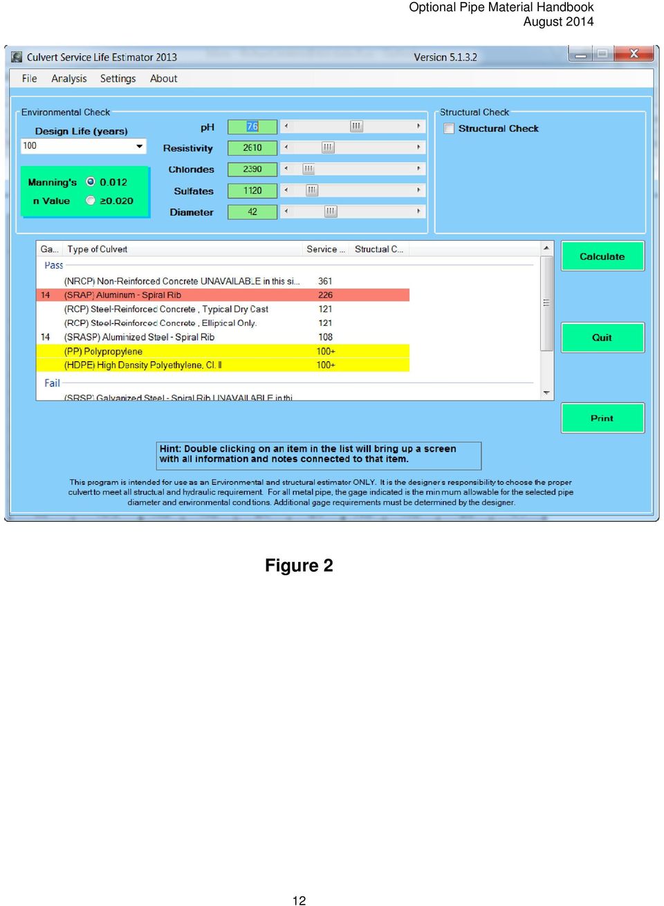
13 No additional consideration should be given to one material over another having less service life if all meet the minimum required. In looking at the printout, culverts made from concrete, aluminum, aluminized steel, polypropylene, high density polyethylene class II and F949 PVC all meet the 100 year DSL. By changing the DSL to 50 years as shown in Figure 3, galvanized steel is now allowable and the required thickness is reduced for the aluminized steel option. Figure 4 illustrates that changing the pipe size can also increase or decrease the expected service life of concrete pipe. Figure 3 13

14 Figure 4 14

15 3.2 Special Cases (Jack and Bore Casings, Ductile Iron Pipe, any Ferrous Metals) When a culvert is to be installed by jack and boring instead of open cutting, the designer should evaluate using the jacked and bored casing as the conveyance pipe. Use of the casing for this purpose has been allowed, however, this was not the original intent for its use. Jack and bore installation is usually specified on high AADT roadways or under railroads, both of which are applications where open cutting often causes significant impacts on users. Thus, this example will assume the typical 100 year DSL for jack and bore installations. The following steps should be used to determine the casing requirements. 1. Run the Service Life Estimator Program or use the figures or tables in Appendix B with site specific environmental parameters. If the casing or pipe will be exposed to water (surface or ground) for extended periods of time the environmental parameters of the water should be compared with that of the soil and those testing results that produce the shortest service life for the galvanized steel option should be used. 2. To be conservative, deduct 10 years from the Estimated Service Life of the galvanized steel option generated by the program. 3. Determine the pitting rate by dividing the wall thickness of the galvanized steel option estimated by the program by the estimated service life determined (ESL - 10 years) in Step 2. From FDOT Drainage Manual Appendix E, identify the wall thickness of the gage pipe called out on the output. Pitting Rate GageThickness ESL(years) 0.xxx inches year Knowing the Pitting Rate, the Required Wall Thickness can be determined by multiplying the Design Service Life for the application by the Pitting Rate. Required Wall Thickness = Pitting Rate x (DSL) Using the galvanized steel option shown on Figure 3: Estimated Service Life for Galvanized Steel Culvert = 57 years. Deduct 10 years from this: 57 yrs yrs. = 47 yrs. 14 gage = inches (thickness of 14 gage galvanized steel culvert per FDOT Drainage Manual Appendix E) 15

16 Therefore the Pitting Rate = / 47 = inches/year Optional Pipe Material Handbook Required Wall Thickness = 100 years (Design Service Life) x (Pitting Rate) = inches In summary, the use of a steel casing with a wall thickness of at least inches would be required. A note such as: For corrosion purposes, steel casing must have a minimum wall thickness of inches should be included in the plans. The required wall thickness is for corrosion purposes only. Greater wall thicknesses are typically required for the structural loadings associated with the jacking of the casing. In the event that the designer elects to use the casing as the conveyance pipe, additional consideration must be given to joint integrity and impact to the roadway if a joint failure was to occur. For instance, when welding is used to join a jacked pipe, the weld might not be around the full circumference of the pipe. If that welded pipe however was to now carry stormwater as the conveyance pipe, the weld must be fully around the pipe circumference to prevent leakage and sand infiltration. When using the casing alone is not allowed, a note disallowing this practice should be placed in the plans to communicate to the Contractor that a VECP (Value Engineering Change Proposal) eliminating the interior pipe will not be approved. 16

17 Chapter 4 - Project Structural Evaluation Optional Pipe Material Handbook After performing the corrosion analysis, the next step in determining the allowable optional material is to determine the structural adequacy of these materials. This analysis is done using FDOT Drainage Manual Appendix E. The information provided in the FDOT Drainage Manual Appendix E was developed based on criteria found in AASHTO LRFD Bridge Design Specifications, Section 12. For each of the allowed options from the corrosion analysis, verify that the depth of backfill over the pipe is between the minimum and maximum fill heights on FDOT Drainage Manual Appendix E. If the cover height is outside the limits, the following options are available as discussed below: 1. The flow line of the pipe could possibly be adjusted if other design criteria are not violated. 2. The gage of metal pipe or the class of concrete pipe may be increased. The engineer should verify that the specified thicker gage is available for the corrugation specified. 3. The material may be eliminated as an option for the job. The Plans Preparation Manual requires that the acceptable type or types of pipe materials have to be called out in the plans. Required class of concrete or gage and corrugation for metal pipe are established using the FDOT Drainage Manual Appendix E. The example below, using the data shown on Figure 2, illustrates general guidelines for using FDOT Drainage Manual Appendix E on cover requirements. 17

18 Project Conditions: Storm Drain application, 42 inch pipe, DSL 100 years, minimum height of cover 7 feet, maximum height of cover 25 feet, and corrosion parameters listed in Figure 2. The allowable materials to be checked (from Fig. 2, the Culvert Service Life Estimator) are as follows: 14 gage aluminized steel, 14 gage aluminum, F949 PVC, PP and HDPE Class II Concrete (RCP and NRCP) All concrete pipes have the same cover requirements and will therefore be addressed as concrete pipe for this example. The structural analysis to determine allowable pipe materials is shown below: A. Check minimum fill heights, using FDOT Drainage Manual Appendix E. All materials meet the minimum fill height limitations. B. Check the maximum fill height for Concrete Pipe, using FDOT Drainage Manual Appendix E. According to Appendix E, concrete pipe must be Class IV or greater. C. Check the maximum fill height for steel pipe. Use the table Steel - Round Pipe - Spiral Rib This table applies to both galvanized steel pipe and aluminized steel pipe. Referring to the same table, 14 gage 42 inch aluminized steel pipe is acceptable because the height of fill does not exceed the maximum fill height allowed by FDOT Drainage Manual Appendix E. D. Check the height of fill against the maximum height allowed for the size/gage combination for aluminum pipe using the table Aluminum Round Pipe Spiral Rib. In checking the table we find that 42 inch, 16 gage pipe is not available. Thus, the thinnest allowable wall is 14 gage and restrictions are placed on the use of this size and gage combination. To use this size and gage combination, special installation requirements set forth in AASHTO Standard Specifications for Highway Bridges or ASTM B788 as well as the manufacturer s installation recommendations must be detailed in the plans. In addition, before using this size and gage combination, approval must be given by the State Hydraulics Engineer. In lieu of the requirements referenced above for aluminum pipe, the designer may use a lower gage (greater wall thickness) pipe to eliminate the requirement for a design review. For documentation purposes, a note can be added to the printout sheet which 18

19 states: In lieu of design review, use 42 inch 12 gauge. In the example shown above, if there was a concern for minimum cover, the designer would not only consider elliptical concrete pipe but also evaluate the use of the metal pipe arch options It should be noted that the fill heights shown in the FDOT Drainage Manual Appendix E are calculated using a very conservative approach. In those cases where the designer encounters very high or very shallow fill heights we encourage the designers to use methods set forth in AASHTO LRFD Bridge Design Specifications, Section

20 Chapter 5 - Documentation Optional Pipe Material Handbook Justification for allowing or eliminating a pipe material is required. Documentation requirements can be found in Chapter 6 of the Drainage Manual. Requirements include the required Design Service Life for the application, environmental data, and the results of the structural evaluation. An excellent form of corrosion analysis documentation is provided in the printout from the Culvert Service Life Estimator Program. The environmental parameters for the specific site, the Estimated Service Life, and the materials that fail to meet or exceed the Design Service Life are documented on the printout. Also, additional comments may be added for documentation purposes. An example would be; Not allowed per FDOT Drainage Manual Appendix E ". 20

21 Chapter 6 - Specifying Optional Pipe Materials in the Contract Plans For cross drains, storm drains, french drains, and gutter drains, optional pipe materials are to be shown in the plans as illustrated in the Plans Preparation Manual. The Optional Pipe Tabulation Sheet includes the size, class of concrete, gage and corrugation and type of metal, and type of plastic pipe are to be included in this tabulation. For specifying optional side drains on a project, two approaches are available: 1. Specify only the pipe sizes in the plans - if all materials meet the environmental and structural requirements the designer need only specify the pipe size in the plans. When only the size is specified in the plans, the contractor has the option to use any material allowed by specification meeting the minimum class or gage contained in the specifications. If a material is not allowed on a side drain application(s), the plans should include a note disallowing the use of that specific material. If this option is chosen, then pipes having n-values greater than will be allowed. Thus, if a designer wishes to use only n-value pipes, option 2, below, must be utilized. 2. Specify allowable side drain pipe materials on the optional pipe plan sheet - in such cases, the Contractor is restricted to the plan sheet options. This plans preparation approach is commonly used when shallow roadside ditches or larger side drain sizes create low pipe cover clearances, eliminating pipes with higher cover requirements. When elliptical or pipe arch pipe are the allowed options, the designer should call out the specified size, class, gage, and corrugations in the plans with payment to be made using the equivalent round size. When round pipes meet the required clearances, elliptical and arch pipes should not be listed as options since they are generally more expensive than their round equivalents. For example, if round concrete and arch metal pipe qualify due to low clearance requirements, elliptical RCP should not be listed as an option since it will likely be more expensive than round concrete pipe. When specifying pipe options on the Optional Pipe Tabulation Sheet, pipes may be called out individually, by storm drain system, by station to station, or any combination of these groupings. Additionally, optional pipes may be identified as a group and then certain pipes within the group accepted and assigned a different list of optional materials. The Plans Preparation Manual shows examples of these approaches. The focus of using groups rather than evaluating and listing each pipe is to provide a fair, competitive pipe supply market with a reasonable level of effort on the part of the 21
22 designer. In general, if the designer needs more than one Optional Pipe Tabulation Sheet on a project, he has gone into too much detail in specifying pipe options and should consider employing more groups of pipes rather than listing pipe by pipe allowable materials. In some low clearance situations, a single concrete pipe may be allowed but a metal arch culvert may not satisfy minimum cover. In such cases, a multiple, smaller metal pipe may have the required hydraulic capacity and minimum cover. For example, consider the case where a 60, n = cross drain, is required for hydraulic capacity but metal pipe, even in arch shape, does not provide the required minimum clearance in FDOT Drainage Manual Appendix E. In such a case, double 48 metal pipes should be checked for hydraulic capacity and, if hydraulically acceptable, the minimum clearance and physical fit within the channel should be verified. Multiple barrel culverts are more susceptible to debris clogging and are likely to be generally more costly, especially considering the additional headwall costs. Typically, double pipes are not used for storm drains due to the required size and cost of the adjacent drainage structures. Occasionally, broad, shallow creeks crossing roadways will require triple or quadruple cross drain pipes in parallel to make efficient use of the pipe cross section or due to pipe clearance requirements. For design/build projects, an optional materials analysis is still required and either an optional materials tabulation sheet included in the construction plans or the pipe material which is to be installed should be documented somewhere in the plans. 22
23 Appendix A Example Project 23
24 Example Project The project consists of the widening and resurfacing of a state road in northern Leon County, Florida. This particular section of roadway contains both rural and urban sections. The project design includes the following: Side drain replacement Cross drain replacement and extensions to existing culverts Storm drain (new design) French drain (new design) Gutter drain (new design) For this example, each application will be addressed and will include a determination of the design service life, commonly asked questions and proposed solutions to those questions. Side Drains under Driveways For this example, we will assume that the soils data provided was fairly consistent throughout the project, therefore the data from the boring having the most stringent values was used in the environmental analysis. Pipe sizes range from 18 inches to 30 inches in diameter. Although actual calculations determined that in certain locations a 12 inch pipe would satisfy the hydraulics, the Drainage Manual recommends a minimum size of 18 inches. Referring to Table 6-1 on page 5, we located the Side Drain column. From the table we see that all highway facilities require a 25 year design service life. Use the Culvert Service Life Estimator program to determine the materials allowed from the environmental standpoint. At this particular location an 18 inch pipe is needed. See Figure 5, below, for results. From the print out we find that the following materials meet the environmental criteria established to meet the 25 year Design Service Life: 16 gage Aluminum, 16 gage aluminized steel, 16 gage galvanized steel, concrete, polypropylene, polyethylene and PVC pipe. 24
25 Figure 5 25
26 The next step in our selection process is to check the structural capacity of the pipe materials allowed. Using FDOT Drainage Manual Appendix E we can check for the minimum and maximum fill height requirements. Throughout the project the minimum amount of fill over the pipe to the bottom of the flexible pavement did not fall below 30 inches, except for two driveways having 10 of cover to the bottom of the flexible pavement. Assume flexible pavement thickness of 3 inches. Also, throughout the project the maximum amount of cover was 4 feet. The following steps were followed to check structural capacity: A. Check minimum fill heights, FDOT Drainage Manual Appendix E, Flexible Pavement. Knowing that the minimum height of cover is not less than 30 inches, each material is checked. All materials meeting the environmental requirements also meet the minimum fill height requirements except for the two shallow driveways. For the two driveways with a clearance of 10, only concrete pipe (RCP, NRCP), with a minimum required cover of 12 to the top of the flexible pavement may be used. B. Check the maximum fill height for Concrete Pipe, FDOT Drainage Manual Appendix E, Table Concrete Pipe - Round. We have a maximum fill height of 4 feet, therefore, according to the table, concrete pipe meeting the requirements of Class I is allowed. NOTE: Section 430 of the standard specifications states that concrete pipe used as side drain must meet the strength requirements of Class I pipe at minimum unless the Class is specifically called out in the plans. C. Check the maximum fill height for steel pipe. Use the table Round Pipe - 2 2/3" x ½" Corrugation. This table applies to both galvanized steel pipe and aluminized steel pipe. Each size is checked to assure that the size/gage combination meeting the environmental criteria has an allowed maximum fill height greater than or equal to 4 feet. In looking at the table to determine the acceptability of galvanized steel pipe we find that the size and gauge combination of, 16 gauge, 18 inch, would be allowed with a fill height up 100 feet or more, therefore, 16 gauge 18 inch galvanized steel pipe is an option. This same process is followed for the aluminized steel pipe. The aluminized steel pipe is also allowed. D. Check the height of fill against the maximum height allowed for the size/gage combination for aluminum pipe using the table Round Pipe 2 2/3" x ½" Corrugation. In checking the table we find that for 18 inch, 16 gauge pipe is allowed with fill heights up 83 feet. E. Check the maximum fill height for Polyethylene, Polypropylene and PVC pipe using FDOT Drainage Manual Appendix E. From Appendix E the maximum fill height allowed for Polyethylene (17 ft), Polypropylene (19 ft) and PVC (42 ft) are all greater than 4 ft and therefore are allowed. 26
27 All pipe materials shown on the output meet the maximum fill height requirements. Specification 430, Type of Pipe to Be Used, of the Standard Specifications for Road and Bridge Construction states that the Contractor may use any material referred to in that particular section unless a specific type of pipe is called out in the plans. Note, since all materials allowed for use under the specification meet the environmental and structural requirements the designer may elect to tabulate the sizes required. If we could not have used all of the materials called out in Section 430, we would tabulate in the plans those materials meeting the environmental and structural requirements. When looking at optional pipe materials we are generally looking at the round pipe options. In those cases where minimum cover restricts the use of round pipe you should look at the elliptical and pipe arch pipes. In low cover situations, if elliptical RCP will not satisfy the minimum allowable cover, then multiple smaller pipes may suffice if the ditch cross section is wide enough. Another option may be calling out a larger round pipe and burying to allow for silting up to the flow line. Side Drains under Intersecting Streets For the sake of this example, let us say that there are approximately 125 side drain locations throughout the project. Of the 125 locations, 25 are located under intersecting streets. Although these have been identified as side drains, they will be designed using cross drain criteria (see note 4 to Table 6-1, located on page 6). Referring to Table 6-1 on page 5 to determine the required Design Service Life and locating the cross drain column, we find that there may be as many as two different design service life requirements. Of the 25 side drain/cross drain locations in this example problem, let us assume that 10 of the planned culverts would be identified as being located on a minor facility. From Table 6-1, a minor facility is defined as a facility which is permanent construction where design traffic volume is less than 1600 AADT and the maximum cover does not exceed 10 feet. In our example, these roads would be those small feeder roads which tie into the major thoroughfare and would fall under the category requiring a 50 year design service life. Environmental data is the same as that used for the side drain analysis above as documented. Examining Figure 3, Polyethylene, Polypropylene, 14 gage galvanized steel, 16 gage aluminized steel, 14 gage aluminum, NRCP, and RCP meet the environmental criteria required to obtain a 50 year DSL. Note that NRCP and F949 PVC are unavailable above 36 diameter. The next step is to check for structural adequacy. This process is identical to the structural check shown above in the previous section dealing with the other side drains. The remaining 15 side drain/cross drains fall under the category requiring a 100 year design service life. Referring to Table 6-1 on page 5, a major facility is permanent construction of (1) roads using an urban or suburban typical section, or (2) limited 27
28 access facilities, or (3) any roadway where design traffic volume is greater than 1600 AADT. Having determined the required design service life to be 100 years, we are ready to perform the environmental analysis. Environmental data is the same as that used for the previous side drain analyses. Examining Figure 2, Polyethylene, Polypropylene, 14 gage aluminized steel, 14 gage aluminum, and RCP meet the environmental criteria required to obtain a 100 year DSL. Remember from the previous example that NRCP and F949 PVC are unavailable above 36 diameter. The next step is to check for structural adequacy. This process is identical to the structural check shown above in the previous section dealing with the other side drains. Storm Drain Referring to Table 6-1 on page 5 we find that storm drains require either 50 year or 100 year Design Service Life. It should be noted that on a project a combination of the DSL could exist. An example would be where the main storm drain has to be designed to meet the 100 year DSL and the outfall could be designed to meet the 50 year DSL. When choosing the appropriate DSL, use the same steps as those previously stated. Remember, all storm drains do not require the 100 DSL criteria. Refer to the notes on Table 6-1 for guidance on the selection of DSL. The 100 year Design Service Life is required on the following example and was determined to be appropriate because the storm drain system is located on a major facility. The following data were produced by the geotechnical survey and the field review did not give any indications that these values were suspect. These values are from the most aggressive test site along the subsection of the project as grouped by the drainage designer. Ph: 7.6 Resistivity: 2610 Chlorides: 2390 Sulfates: 1120 Diameter (Pipe Size): 42", this size was determined to be needed to handle the flows within this part of the storm drain system. Because this is a storm drain system a onesize (n-0.012) design was used. Size and materials shown here are those the designer would use in performing the structural analysis. 28
29 This data is input into the Culvert Service Life Estimator Program. Figure 2 shows those materials allowed by virtue of their Estimated Service Life (ESL). The designer then performs the structural analysis as previously described. Cross Drain Cross drains can require 50 or 100 year DSL s. Refer to Table 6-1. Check the notes to identify which DSL is appropriate for your application. It is possible to have cross drains on the project that require the various DSL s. Determination of environmental data to use and structural analysis are the same as previously described. When sizing cross drains, only one n-value (usually since most cross drains in Florida are outlet controlled) need be considered. However, when the cross drain hydraulics are inlet controlled and metal pipes are environmentally acceptable, the designer should list standard corrugated metal pipes within the allowable options. Standard corrugation metal pipe is often less expensive than spiral rib metal pipe and is available in larger sizes than spiral rib pipe. When extending cross drains, preference should be given to using the same existing pipe materials. Existing pipe should be replaced or lined if, upon inspection, the pipe displays evidence of corrosion or has structural cracking. When the extension of an existing pipe results in a minor transgression of the structural clearance criteria, the designer should consider providing additional structural support for the pipe extension rather than replacing the entire cross drain. Encasing the extension in flowable fill will typically provide the needed additional support. Gutter Drain From Table 6-1 on page 5 we identify a required DSL of 25 years for the gutter drain. The process is the same as that for performing the analysis for the side drain application previously discussed. However, when sizing gutter drain and choosing materials, only materials having an n - value of > should be used. If possible, specify pipe of sufficient length to eliminate joints. French Drain In selecting the DSL appropriate for french drain, the location of the french drain system determines which DSL to use. Consider the case where the french drain is being placed in an urban location along the trunk line located under the sidewalk, parallel and adjacent to the roadway: the french drain is not under the roadway, but replacement of the French drain would require reconstruction of the outside lane due to the depth of cut and angle of repose of the soil. Even though the french drain reconstruction might be performed using sheeting to avoid impacting the roadway, the cost of the sheeting 29
30 makes this installation costly enough to elevate the service life to 100 years. A similar situation occurs when a pipe installation is adjacent to buildings: in such cases, sheeting may also be required making the installation or replacement costly and thus earning a 100-year DSL. Appendix B Corrosion Tables and Charts 30
31 31 Optional Pipe Material Handbook
32 Resistivity ph Estimated Service Life: (SL) = 17.24{Log 10 R - Log 10 [ (Log 10 ph)]} for 5<pH 7.3 (SL) = 1.84 R 0.41 for 7.3 <ph <9 32
33 33 Optional Pipe Material Handbook
34 TABLE 6.3 Estimated Service Life vs. ph and Resistivity for 16 ga. ALUMINIZED STEEL Culvert Pipe Resistivity ph to Estimated Service Life (SL) = 50{Log 10 R - Log 10 [ (Log 10 ph)]} for 5.0 <ph<7.0 (SL) = 50(Log 10 R ) for 7.0 <ph <8.5 (SL) = 50{Log 10 R - Log 10 { Log 10 [7-4(pH - 8.5)]}} for 8.5<pH <9.0 34
35 35 Optional Pipe Material Handbook
36 TABLE 6.4 Estimated Service Life vs. ph and Resistivity for 16 ga. ALUMINUM Culvert Pipe Resistivity Optional Pipe Material Handbook ph & & & & & & & & & & & Where: SL = Years to first perforation Service Life (SL) = T p / (R ph + R r ) T p = Thickness of pipe (inches) R ph = Corrosion rate for ph (inches/year) R r = Corrosion rate for resistivity (inches/year) 36
37 37 Optional Pipe Material Handbook
38 TABLE 6.5 Estimated Service Life vs. ph and Chlorides for 60" Dia. REINFORCED CONCRETE Culverts at 1500 ppm Sulfate Concentration Chlorides ph Conversion Factors for Different Size Culverts Pipe Dia. Mult. By Pipe Dia. Mult. By SL Reduction Factors for Sulfates Sulfate Content Subtract from SL Note: Sulfate derating not applicable When Type V cement is used. Service Life (SL) = 1000(1.107 C C D 1.22 K W ) x10 10 (ph ) x10-3 (S) Where: C = Sacks of cement per cubic yard D = Steel depth in concrete K = Environmental chloride concentration in ppm W = Total percentage of water in the mix S = Environmental sulfate content in ppm 38
X Planning X Quality X Maintenance & Operations
 Delaware Department of Transportation Division of Transportation Solutions Design Guidance Memorandum Memorandum Number 1-20 Revised 1. Road Design Manual 2. Bridge Design Manual 3. Utilities Design Manual
CULVERT AND STORM SEWER PIPE MATERIAL POLICY ON FEDERALLY FUNDED LOCAL AGENCY PROJECTS UPDATED March 2013
 CULVERT AND STORM SEWER PIPE MATERIAL POLICY ON FEDERALLY FUNDED LOCAL AGENCY PROJECTS UPDATED March 2013 Background Section 5514, a final rule for SAFETEA-LU was issued on November 15, 2006 and became
Nebraska Department of Roads Drainage and Erosion Control Manual December 2011 Appendix C: Pipe Material Policy Page C-1 PIPE MATERIAL POLICY
 Appendix C: Pipe Material Policy Page C-1 PIPE MATERIAL POLICY Policy: This policy will replace all previous policies regarding the selection of pipe material for cross drains, drive pipe, drop pipe, storm
SECTION 08000 STORM DRAINAGE TABLE OF CONTENTS
 SECTION 08000 STORM DRAINAGE 08010 DESIGN A. Location B. Sizing TABLE OF CONTENTS 08020 MATERIALS A. Pipe Materials B. Structure Materials C. Installation D. Inlets and Outlets 08030 INSPECTIONS AND TESTING
SECTION 02400 - STORM DRAIN SYSTEM
 SECTION 02400 - STORM DRAIN SYSTEM CONTENTS: Part 1 - General... 1 1.01 Work Included... 1 1.02 Related Requirements... 1 1.03 Reference Standards... 1 1.04 Quality Assurance... 1 1.05 Measurement And
State of Illinois Department Of Transportation CONSTRUCTION INSPECTOR S CHECKLIST FOR STORM SEWERS
 State of Illinois Department Of Transportation CONSTRUCTION INSPECTOR S CHECKLIST FOR STORM SEWERS While its use is not required, this checklist has been prepared to provide the field inspector a summary
SECTION 724 PIPE CULVERTS
 SECTION 724 PIPE CULVERTS 724.1 Description. This work shall consist of providing pipe or pipe arch of the diameter or shape designated, laid upon a firm bed and backfilled as specified. Where appropriate
June 2007 CHAPTER 7 - CULVERTS 7.0 CHAPTER 7 - CULVERTS 7.1 GENERAL
 7.0 7.1 GENERAL For the purpose of this manual, culverts are defined as structures that are completely surrounded by soil and located below the surface of the roadway parallel to the general direction
DIVISION 2 - SEWERAGE AND DRAINAGE SECTION 02720 - STORM DRAIN SYSTEMS PART 1 - GENERAL
 DIVISION 2 - SEWERAGE AND DRAINAGE SECTION 02720 - STORM DRAIN SYSTEMS PART 1 - GENERAL 1.01 DESCRIPTION A. Furnish and install all storm drains, including manholes, inlets, service lines and other appurtenant
DIVISION 4300 STORM DRAINAGE
 DIVISION 4300 STORM DRAINAGE SECTION 4305 STORM SEWER PART 1 - GENERAL 1.01 SCOPE This section covers the construction of storm sewers for the collection and transport of stormwater runoff. 1.02 REFERENCES
ITD Pipe Materials Selection & Specification Procedures. July 2011
 ITD Pipe Materials Selection & Specification Procedures July 2011 INTRODUCTION: This technical memorandum is written as a guide to the selection of compliant pipe materials and the elimination of non-compliant
8-11 Structural Analysis and Fill Height Tables... 42 8-11.1 Pipe Cover... 43 8-11.2 Shallow Cover Installation... 43 8-11.3 Fill Height Tables...
 Contents Chapter 8 Pipe Classifications and Materials...1 8-1 Classifications of Pipe... 1 8-1.1 Drain Pipe... 2 8-1.2 Underdrain Pipe... 2 8-1.3 Culvert Pipe... 3 8-1.4 Storm Sewer Pipe... 7 8-1.5 Sanitary
TECHNICAL NOTE Culvert Sliplining and Lining of Casings with HPPipe
 TECHNICAL NOTE Culvert Sliplining and Lining of Casings with HPPipe TN 5.14 February 2010 Introduction It may be at times necessary, in an aging infrastructure, to rehabilitate drainage and sanitary lines
Section 2100-Trenching and Tunneling
 SECTION 5200 - STORM SEWER PART 1 - GENERAL 1.01 SCOPE: This Section covers installation of storm sewer mains and culverts. Topics include permits and fees, trench widths, pipe laying, bedding, initial
Chapter 22. Lump Sum Project Guidelines
 Chapter 22 Lump Sum Project Guidelines 22.1 General...22-1 22.2 Project Selection...22-3 22.3 Plans Preparation...22-5 22.4 Preliminary Estimate...22-7 22.5 Specifications...22-9 22.6 Contracts Administration...22-11
MEMORANDUM: RECOMMENDATIONS FOR PIPE MATERIAL SELECTION
 MEMORANDUM: RECOMMENDATIONS FOR PIPE MATERIAL SELECTION Moser and Associates Engineering for CDOT Region 6 Date: 9/30/10 Memorandum to File: Recommendations for Pipe Material Selection for Construction
STORM DRAINS CHAPTER 7
 CHAPTER 7 Chapter 7 - Storm Drains A storm drain is a drainage system that conveys water or stormwater, consisting of two or more pipes in a series connected by one or more structures. Storm drains collect
Section 402. STORM SEWERS
 402.02 Section 402. STORM SEWERS 402.01. Description. This work consists of constructing storm sewers of the size and class required, including excavation, bedding, and backfill. 402.02. Materials. Provide
Local Road Assessment and Improvement Drainage Manual
 Local Road Assessment and Improvement Drainage Manual Donald Walker, T.I.C. Director, author Lynn Entine, Entine & Associates, editor Susan Kummer, Artifax, design Transportation Information Center University
SECTION 55 PIPE FOR STORM DRAINS AND CULVERTS (FAA D-701)
") SECTION 55 PIPE FOR STORM DRAINS AND CULVERTS (FAA D-701) 55-1 GENERAL The Contractor shall perform all work required by the plans for construction of pipe for storm drains, precast polymer trench drains
SECTION 55 PIPE FOR STORM DRAINS AND CULVERTS (FAA D-701) 55-1 GENERAL The Contractor shall perform all work required by the plans for construction of pipe for storm drains, precast polymer trench drains
Chapter 9 Storm Sewers
 Contents 1.0 Introduction... 1 2.0 Design Storms... 1 2.1 Minor Event... 1 2.2 Major Event... 1 3.0 Pipe Material and Size... 2 3.1 Pipe Material... 2 3.2 Minimum Pipe Size... 2 3.3 Service Life... 2 3.4
PUBLIC WORKS DESIGN, SPECIFICATIONS & PROCEDURES MANUAL LINEAR INFRASTRUCTURE
 REGION OF PEEL PUBLIC WORKS DESIGN, SPECIFICATIONS & PROCEDURES MANUAL LINEAR INFRASTRUCTURE Storm Sewer Design Criteria REVISED July 2009 PUBLIC WORKS STORM SEWER DESIGN CRITERIA TABLE OF CONTENTS 1.0
SECTION 33 41 13 PUBLIC STORM UTILITY DRAINAGE PIPING
 SECTION 33 41 13 PUBLIC STORM PART 1 - GENERAL 1.01 SECTION INCLUDES A. Storm drainage piping, fittings, and accessories at proposed station areas and locations other than under and immediately adjacent
STRUCTURES. 1.1. Excavation and backfill for structures should conform to the topic EXCAVATION AND BACKFILL.
 STRUCTURES 1. General. Critical structures may impact the integrity of a flood control project in several manners such as the excavation for construction of the structure, the type of foundation, backfill
Preliminary Design Report Clay County, Florida Carpet n Drapes Culvert Repair and Rehabilitation July 21, 2006
 Clay County, Florida Carpet n Drapes Culvert Repair and Rehabilitation July 21, 2006 1.0 Background and Repair and Rehabilitation Recommendation Clay County has contracted Camp Dresser & McKee Inc. (CDM)
CHAPTER 850 PHYSICAL STANDARDS
 HIGHWAY DESIGN MANUAL 850-1 CHAPTER 850 PHYSICAL STANDARDS Topic 851 - General Index 851.1 - Introduction This chapter deals with the selection of drainage facility material type and sizes including pipes,
SECTION 108 - INLETS 108.1 INLET LOCATIONS
 Greene County Design Standards -Adopted April 5, 1999 SECTION 108 - INLETS SECTION 108 - INLETS 108.1 INLET LOCATIONS 108.2 INLET INTERCEPTION CAPACITIES 108.2.1 Clogging Factors 108.3 INTERCEPTION AND
SECTION 5: SANITARY SEWER SYSTEM DESIGN
 SECTION 5: SANITARY SEWER SYSTEM DESIGN 5.01 GENERAL Sanitary sewer improvements shall be designed to serve the ultimate level of City development as defined in the General Plan and the Wastewater Facilities
2011 HYDRAULICS MANUAL
 STATE OF LOUISIANA DEPARTMENT OF TRANSPORTATION AND DEVELOPMENT P.O. Box 94245 Baton Rouge, Louisiana 70804-9245 http://www.dotd.la.gov/ HYDRAULICS MANUAL Hydraulics (225) 379-1306 PREFACE The following
Culvert Repair, Materials, and Structural Design 4.4-1
 Culvert Repair, Materials, and Structural Design 4.4-1 4.4 Culvert Materials 4.4.1 General Culverts are primarily made with reinforced concrete, corrugated metal, and more recently, solidwall, profile
8.1.3 General Design Guidelines. The following guidelines shall be used when designing inlets along a street section:
 . Introduction Presented in this chapter are the criteria and methodology for design and evaluation of storm sewer inlets located in Town of Castle Rock. The review of all planning submittals will be based
Electric Engineering Division FIBER CONDUIT RULES AND REGULATIONS
 Electric Engineering Division FIBER CONDUIT RULES AND REGULATIONS TABLE OF CONTENTS I. RULES AND REGULATIONS A. TABLE OF CONTENTS... 2 B. TERMS AND DEFINITIONS... 3 C. DEVELOPER S/CONTRACTOR S RESPONSIBILITIES...
Repair or Replacement - Band-Aids vs. Surgery
 Repair or Replacement - Band-Aids vs. Surgery Using RCP for the Replacement of Failed or Undersized Culverts www.concrete-pipe.org Introduction and Background Our Nation s infrastructure owners are facing
DESCRIPTION OF STORMWATER STRUCTURAL CONTROLS IN MS4 PERMITS
 DESCRIPTION OF STORMWATER STRUCTURAL CONTROLS IN MS4 PERMITS Phase I MS4 permits require continuous updating of the stormwater system inventory owned and operated by the MS4. They also include inspection
CHAPTER 14 SECTION 1
 SECTION 1 S SECTION 1 S JANUARY 6, 006 S CH14-100 SECTION 1 S TABLE OF CONTENTS SECTION 1 S 1.1 INTRODUCTION... CH14-103 1. HYDRAULIC DESIGN... CH14-104 1..1 ALLOWABLE STORM WATER CAPACITY...CH14-104 1..
SANITARY SEWER SPECIFICATIONS
 SANITARY SEWER SPECIFICATIONS OCTOBER 2003 HARVEST-MONROVIA WATER, SEWER, AND FIRE PROTECTION AUTHORITY SECTION 1.00 1.10 Purpose The purpose of this document is to assemble the sewer specifications, policies,
SECTION 02630 STORM DRAINAGE SYSTEM
 SECTION 02630 PART 1 - GENERAL 1.01 DESCRIPTION A. Section includes specifications for storm drainage systems including modifications and connections to existing storm drainage systems. 1.02 REFERENCE
Estimating Stormwater System Annual Maintenance and Repair Costs - A GIS Approach
 October 5 2011 Estimating Stormwater System Annual Maintenance and Repair Costs - A GIS Approach 2011 SESWA Annual Conference 2011 Southeast Stormwater Associated Annual Conference Presentation Overview
BEST PRACTICE GUIDELINES FOR CULVERT LINER SELECTION
 BEST PRACTICE GUIDELINES FOR CULVERT LINER SELECTION GENERAL Rehabilitation of culverts with pipe liners is one of several methods available for extending the life of an existing culvert. It is often cost
Ohio Department of Transportation Division of Production Management Office of Geotechnical Engineering. Geotechnical Bulletin PLAN SUBGRADES
 Ohio Department of Transportation Division of Production Management Office of Geotechnical Engineering Geotechnical Bulletin GB 1 PLAN SUBGRADES Geotechnical Bulletin GB1 was jointly developed by the Offices
Safe & Sound Bridge Terminology
 Safe & Sound Bridge Terminology Abutment A retaining wall supporting the ends of a bridge, and, in general, retaining or supporting the approach embankment. Approach The part of the bridge that carries
SPECIFICATIONS FOR CULVERT PIPE
 SPECIFICATIONS FOR CULVERT PIPE USED IN SCDOT HIGHWAY APPLICATIONS SARAH L. GASSMAN, PH.D. SUBMITTED TO THE SOUTH CAROLINA DEPARTMENT OF TRANSPORTATION AND THE FEDERAL HIGHWAY ADMINISTRATION OCTOBER 2005
SECTION 6A STORM DRAIN DESIGN Mar. 2002 S E C T I O N 6A STORM DRAIN - DESIGN
 S E C T I O N 6A STORM DRAIN - DESIGN 6A.l Scope 6A.2 Storm Water Quantity 6A.3 Storm Drain Hydraulics 6A.4 Depths 6A.5 Locations 6A.6 Curved Storm Drains 6A.7 Manholes 6A.8 Catch basins 6A.9 Storm Drain
SECTION 02720 SANITARY SEWER AND STORM DRAIN SYSTEMS
 SECTION 02720 SANITARY SEWER AND STORM DRAIN SYSTEMS PART 1 GENERAL 1.01 SECTION INCLUDES A. The requirements for pipe material and installation in sewer and drainage collection systems. All materials
APPENDIX C INLETS. The application and types of storm drainage inlets are presented in detail in this Appendix.
 Storm Drainage 13-C-1 APPENDIX C INLETS 1.0 Introduction The application and types of storm drainage inlets are presented in detail in this Appendix. 2.0 Inlet Locations Inlets are required at locations
CHAPTER 17: STORM SEWER STANDARDS. 17.00 Introduction. 17.01 Administration. 17.02 Standards 17.1
 CHAPTER 17: STORM SEWER STANDARDS 17.00 Introduction 17.01 Administration 17.02 Standards 17.1 17.00 INTRODUCTION The purpose of this chapter is to provide guidance for the design and construction of storm
A perforated conduit such as pipe, tubing or tile installed beneath the ground to intercept and convey ground water. or structures.
 BMP: SUBSURFACE DRAIN Definition A perforated conduit such as pipe, tubing or tile installed beneath the ground to intercept and convey ground water. PurRoses 1. To prevent sloping soils from becoming
SECTION 1 GENERAL REQUIREMENTS
 Page 1 of 6 SECTION 1 GENERAL REQUIREMENTS 1. SCOPE OF WORK: The work to be performed under the provisions of these documents and the contract based thereon includes furnishing all labor, equipment, materials,
SECTION 7- STORM SEWER
 SECTION 7- STORM SEWER 7.1. STORM SEWERS.... 7-1 7.2. SUMP DRAINS... 7-3 7.3. CATCH BASINS... 7-3 7.4. MANHOLES... 7-4 7.5. STORM SEWER CALCULATIONS... 7-4 7.6. CULVERTS AND BRIDGES... 7-5 7.7. OPEN CHANNELS...
Value of Instrumentation Systems and Real-Time Monitoring: An Owner s Perspective
 Value of Instrumentation Systems and Real-Time Monitoring: An Owner s Perspective FHWA NATIONAL GEOTECHNICAL PROGRAM www.fhwa.dot.gov/engineering/geotech Why Geotechnical Instrumentation? Provide warning
CHAPTER 9 STORM DRAINAGE DESIGN AND STORMWATER QUALITY REGULATIONS
 June 27, 2011 Chapter 9 Storm Drainage Design and Stormwater Quality Regulations Table of Contents CHAPTER 9 STORM DRAINAGE DESIGN AND STORMWATER QUALITY REGULATIONS Table of Contents Chapter 9 Storm Drainage
Index. protection. excavated drop inlet protection (Temporary) 6.50.1 6.51.1. Block and gravel inlet Protection (Temporary) 6.52.1
 6.50.1 6.51.1. Block and gravel inlet Protection (Temporary) 6.52.1") 6 Index inlet protection excavated drop inlet protection (Temporary) 6.50.1 HARDWARE CLOTH AND GRAVEL INLET PROTECTION Block and gravel inlet Protection (Temporary) sod drop inlet protection ROCK DOUGHNUT
6 Index inlet protection excavated drop inlet protection (Temporary) 6.50.1 HARDWARE CLOTH AND GRAVEL INLET PROTECTION Block and gravel inlet Protection (Temporary) sod drop inlet protection ROCK DOUGHNUT
DRAINAGE MANUAL CHAPTER VII STORM DRAINAGE SYSTEMS
 TDOT DESIGN DIVISION DRAINAGE MANUAL CHAPTER VII STORM DRAINAGE SYSTEMS August 1, 2012 CHAPTER 7 STORM DRAINAGE SYSTEMS SECTION 7.01 INTRODUCTION 7.01 INTRODUCTION...7-1 SECTION 7.02 DOCUMENTATION PROCEDURES
Storm Drainage Systems 11.9-1
 Storm Drainage Systems 11.9-1 11.9 Gutter Flow Calculations 11.9.1 Introduction Gutter flow calculations are necessary in order to relate the quantity of flow (Q) in the curbed channel to the spread of
SPR PE Steel Reinforced Liner
 ENGINEERED SOLUTIONS SPR PE Steel Reinforced Liner Reline Done Right Contech is your single source for rehabilitation of sanitary & storm sewers, culverts and bridges. Contech Engineered Solutions has
Wastewater Capital Projects Management Standard Construction Specification
 CITY AND COUNTY OF DENVER ENGINEERING DIVISION Wastewater Capital Projects Management Standard Construction Specification 10.1 Precast Concrete Pipe 10.1.1 General This section covers material requirements,
CHAPTER 8 CIVIL DESIGN
 CHAPTER 8 CIVIL DESIGN A. GENERAL This Chapter includes standards and design considerations for other civil engineering design in structural, drainage and utilities. Design considerations for electrical
PIPE INSPECTION AND REPAIR. Larry Ritchie
 PIPE INSPECTION AND REPAIR Larry Ritchie February 23, 2010 PIPE INSPECTION AND REPAIR The Florida Department of Transportation builds and maintains hundreds of miles of underground infrastructure as part
Chapter 3 CULVERTS. Description. Importance to Maintenance & Water Quality. Culvert Profile
 Chapter 3 CULVERTS Description A culvert is a closed conduit used to convey water from one area to another, usually from one side of a road to the other side. Importance to Maintenance & Water Quality
SPECIFICATION FOR PIPE SUBSOIL DRAIN CONSTRUCTION
 SPECIFICATION FOR PIPE SUBSOIL DRAIN CONSTRUCTION 1. SCOPE Pipe subsoil drains shall be constructed in accordance with this specification and in conformity with the lines, grades and cross-sections shown
550 PIPE CULVERTS, SEWERS AND DRAINS
 551.01 550 PIPE CULVERTS, SEWERS AND DRAINS 551 GENERAL 551.01 Description 551.02 Materials 551.03 Excavation 551.04 Protection of Excavation 551.05(a) Bedding for Rigid Pipe 551.05(b) Bedding for Non-Rigid
Table 4.9 Storm Drain Inlet Protetion Applicable for
 BMP C220: Storm Drain Inlet Protection Purpose To prevent coarse sediment from entering drainage systems prior to permanent stabilization of the disturbed area. Conditions of Use Type of Inlet Protection
Sewer Rehabilitation Design Requirements
 Sanitary Sewer Overflow (SSO) Control and Wastewater Facilities Program Sewer Rehabilitation Design Requirements City of Baton Rouge/Parish of East Baton Rouge Department of Public Works Submitted by Prepared
DESIGN INFORMATION BULLETIN NO. 83-03 CALTRANS SUPPLEMENT TO FHWA CULVERT REPAIR PRACTICES MANUAL
 DESIGN INFORMATION BULLETIN NO. 83-03 CALTRANS SUPPLEMENT TO FHWA CULVERT REPAIR PRACTICES MANUAL This document establishes uniform procedures to carry out the highway design functions of the California
SUBDRAINS AND FOOTING DRAIN COLLECTORS. A. Construct subdrains, subdrain cleanouts and outlets, and footing drain collectors.
 SUBDRAINS AND FOOTING DRAIN COLLECTORS PART 1 - GENERAL 1.01 SECTION INCLUDES A. Subdrains B. Subdrain Cleanouts and Outlets C. Footing Drain Collectors D. Storm Sewer Service and Connections 1.02 DESCRIPTION
IS THAT LINER THICK ENOUGH?
 IS THAT LINER THICK ENOUGH? Philip McFarlane, Opus International Consultants Ltd ABSTRACT The amount of pipeline rehabilitation being undertaken in New Zealand is increasing each year. Larger diameter
HDPE PRODUCTS QUALITY, PERFORMANCE AND ECONOMY COMBINED
 QUALITY, PERFORMANCE AND ECONOMY COMBINED LANE S HDPE DRAINAGE PIPE Scan for more information on Lane s HDPE product line. Lane provides the complete product line to meet all your HDPE drainage needs -
Module 3: Sewer Material Lecture 3: Sewer Material
 Module 3: Sewer Material Lecture 3: Sewer Material [NPTEL, IIT Kharagpur, Prof. M.M.Ghangrekar, Department of Civil Engineering Page 1 3.0 SEWER MATERIAL 3.1 Important Factors Considered for Selecting
Module 3 : Sewer Material. Lecture 3 : Sewer Material
 1 P age Module 3 : Sewer Material Lecture 3 : Sewer Material 2 P age 3.1 Important Factors Considered for Selecting Material for Sewer Following factors should be considered before selecting material for
City of Hilshire Village Pine Creek Ln Reconstruction
 City of Hilshire Village Pine Creek Ln Reconstruction OVERVIEW The City will be soliciting bids for the Pine Creek Reconstruction Project with construction scheduled to begin in January 2015. This project
SECTION III-06 Surfacing Page 1 Revised 3/2/10. See the DESIGN GUIDELINES in Section I-06 for requirements for cross slope of the roadway.
 Page 1 Revised 3/2/10 See the DESIGN GUIDELINES in Section I-06 for requirements for cross slope of the roadway. For New/Reconstruction projects: The cross slope of the driving lanes range from 1.5% to
CHAPTER 5. Storm Sewer
 CHAPTER 5 Storm Sewer A. Introduction All proposed developments shall have a properly designed and constructed storm water conveyance system. This chapter deals only with the conveyance system. Storm water
CID STREET INFRASTRUCTURE ASSESSMENT
 ABSTRACT An evaluation of the street infrastructure in Foxberry Estates Phase 1, including pavement condition, verification of construction techniques, and subgrade quality. Recommendations and costs for
DRAFT MAINTAINING HOUSTON S STREETS REPAIR, REHABILITATION, RECONSTRUCTION. Using the Full Range of Tools for a Challenging Job
 MAINTAINING HOUSTON S STREETS REPAIR, REHABILITATION, RECONSTRUCTION Using the Full Range of Tools for a Challenging Job Report To: TTI Committee May 13, 2014 1 Pavement Management - Suggested Treatments
CHAPTER 11 STORM DRAINAGE
 CHAPTER STORM DRAINAGE SECTION PC 0 GENERAL 0. Scope. The provisions of this chapter shall govern the materials, design, construction and installation of storm drainage. Storm water discharge shall be
SD96-11-F. SD Department of Transportation Office of Research. Evaluation of High Density Polyethylene (HDPE) Pipe SD96-11 Final Report
 Pipe SD96-11 Final Report") SD96-11-F SD Department of Transportation Office of Research Evaluation of High Density Polyethylene (HDPE) Pipe SD96-11 Final Report Prepared by Office of Research South Dakota Department of Transportation
SD96-11-F SD Department of Transportation Office of Research Evaluation of High Density Polyethylene (HDPE) Pipe SD96-11 Final Report Prepared by Office of Research South Dakota Department of Transportation
CONCRETE SEGMENTAL RETAINING WALL SYSTEM
 CONCRETE SEGMENTAL RETAINING WALL SYSTEM PART 1: GENERAL SPECIFICATIONS 1.01 Work Included A. Work shall consist of furnishing and constructing a Rockwood Classic 8 with PCS unit segmental retaining wall
Storm Sewer Trenchless Upgrade Alternatives and Recommendations
 Storm Sewer Trenchless Upgrade Alternatives and Recommendations Background Approximately 1,930 feet of the 40-inch and 42-inch CMP storm sewer pipe from manhole M22 to manhole M12 will be evaluated for
ENGINEERING DESIGN GUIDELINES. for SUBDIVISIONS OR COMMERCIAL DEVELOPMENTS
 ENGINEERING DESIGN GUIDELINES for SUBDIVISIONS OR COMMERCIAL DEVELOPMENTS City of Birmingham Department of Planning, Engineering and Permits Engineering Division Office of the City Engineer 2008 TABLE
CONSTRUCTION PERMIT REQUIREMENTS
 CONSTRUCTION PERMIT REQUIREMENTS Any work to be done in the City right-of-way (ROW), in a utility easement, and certain work on private property, requires an Engineering Inspection Permit from the Department
BMP 6.4.6: Dry Well / Seepage Pit
 BMP 6.4.6: Dry Well / Seepage Pit A Dry Well, or Seepage Pit, is a variation on an Infiltration system that is designed to temporarily store and infiltrate rooftop runoff. Key Design Elements Fllow Infiltration
SECTION 5 - STORM DRAINS
 Drainage Criteria Manual SECTION 5 - STORM DRAINS 5.1.0 GENERAL This The purpose of this section discusses briefly is to consider the hydraulic aspects of storm drains and their appurtenances in a storm
CONCRETE SEGMENTAL RETAINING WALL SYSTEM
 CONCRETE SEGMENTAL RETAINING WALL SYSTEM PART 1: GENERAL SPECIFICATIONS 1.01 Work Included A. Work shall consist of furnishing and constructing a Rockwood Vintage TM unit segmental retaining wall (SRW)
TENNESSEE GAS PIPELINE COMPANY, L.L.C.
 TENNESSEE GAS PIPELINE COMPANY, L.L.C. HYDROLOGIC & HYDRAULIC CALCULATIONS FOR WATERBODIES CROSSED BY CONNECTICUT PIPELINE EXPANSION PROJECT CONNECTICUT LOOP Submitted by: Tennessee Gas Pipeline Company,
CITY OF VISTA STANDARD DRAWINGS (PRELIMINARY, FOR REVIEW)
") CITY OF VISTA STANDARD DRAWINGS (PRELIMINARY, FOR REVIEW) January, 2013 THIS SHEET INTENTIONALLY LEFT BLANK TABLE OF CONTENTS DRAINAGE STRUCTURES DRN-01 Corrugated metal pipe drop inlet DNR-02 Storm Drain
CITY OF VISTA STANDARD DRAWINGS (PRELIMINARY, FOR REVIEW) January, 2013 THIS SHEET INTENTIONALLY LEFT BLANK TABLE OF CONTENTS DRAINAGE STRUCTURES DRN-01 Corrugated metal pipe drop inlet DNR-02 Storm Drain
ROOF DRAINS TABLE OF CONTENTS
 Pictorial Index Product Recommendations Roof Drain Selection Factors Sizing Placement Material & Characteristics Pipe Connection Commonly Specified Options Typical Installations TABLE OF CONTENTS ROOF
City of Shelbyville Site Inspection Checklist
 City of Shelbyville Site Inspection Checklist General Information Project Name: KYR10 Permit Number: Date: Project Location: Contractor: Conractor Representative: Inspector's Name: Title: Signature : Weather
RESIDENTIAL ROOFING & RE-ROOFING, ROOF VENTILATION AND ROOF SHEATHING REQUIREMENTS MICHIGAN RESIDENTIAL CODE 2000
 RESIDENTIAL ROOFING & RE-ROOFING, ROOF VENTILATION AND ROOF SHEATHING REQUIREMENTS MICHIGAN RESIDENTIAL CODE 2000 SECTION R905 REQUIREMENTS FOR ROOF COVERINGS R905.1 Roof covering application. Roof coverings
Fabricated Drainage Products
 Fabricated Drainage Products Complete Drainage System Inline Drains are used At the beginning of a drain line Add a new water inlet to an existing drain line using a riser pipe and tee HARCO Surface Drainage
CITY UTILITIES DESIGN STANDARDS MANUAL
 CITY UTILITIES DESIGN STANDARDS MANUAL Book 2 (SW) SW9 June 2015 SW9.01 Purpose This Chapter provides information for the design of open channels for the conveyance of stormwater in the City of Fort Wayne.
PROJECT COST ESTIMATE ASSUMPTIONS AND EXCLUSIONS
 C PROJECT ESTIMATE ASSUMPTIONS AND EXCLUSIONS In support of the alternatives development process, preliminary cost estimates were prepared for each of the three Candidate Build Alternatives. The cost estimates
Township of Enniskillen. Asset Management Plan
 Township of Enniskillen Asset Management Plan 2014 1 TABLE OF CONTENTS Page A. Introduction 3 B. State of Local Infrastructure 4 C. Desired Levels of Service 7 D. Asset Management Strategy 8 E. Financing
GEOTECHNICAL DESIGN MANUAL
 GEOTECHNICAL DESIGN MANUAL CHAPTER 21 GEOTECHNICAL ASPECTS OF PIPE DESIGN AND INSTALLATION NYSDOT Geotechnical Page 21-1 July 18, 2013 (Intentionally left blank) NYSDOT Geotechnical Page 21-2 July 18,
A Research Plan and Report on Factors Affecting Culvert Pipe Service Life in Minnesota
 A Research Plan and Report on Factors Affecting Culvert Pipe Service Life in Minnesota Jeff Marr, Principal Investigator St. Anthony Falls Laboratory University of Minnesota September 2012 Research Project
Section 600 Incidental Construction
 Table of Contents 1. Pipe Culverts... 600-1 A. Endwalls, Inlets, Manholes, and Spring Boxes... 600-5 2. Grade Adjustment of Existing Miscellaneous Structures... 600-8 3. Rebuilt Miscellaneous Structures...
Royal Seal Gasketed Sewer Pipe
 Royal Seal Gasketed Sewer Pipe Royal Seal Gasketed Sewer Pipe Royal Seal gasketed sewer pipe with our specially designed Double Seal Locked-In (DSLI ) gasket is an extremely durable pipe with a leak proof