TEPZZ 9 _88_A_T EP A1 (19) (11) EP A1 (12) EUROPEAN PATENT APPLICATION
|
|
|
- Osborne Price
- 8 years ago
- Views:
Transcription
1 (19) TEPZZ 9 _88_A_T (11) EP A1 (12) EUROPEAN PATENT APPLICATION (43) Date of publication: Bulletin 1/39 (21) Application number: (1) Int Cl.: G01T 1/ (06.01) G03B 42/02 (06.01) G03B 42/04 (06.01) (22) Date of filing: (84) Designated Contracting States: AL AT BE BG CH CY CZ DE DK EE ES FI FR GB GR HR HU IE IS IT LI LT LU LV MC MK MT NL NO PL PT RO RS SE SI SK SM TR Designated Extension States: BA ME (71) Applicant: Agfa HealthCare N.V. 26 Mortsel (BE) (72) Inventors: Pirmann, Anton München (DE) Mair, Stephan 8617 Augsburg (DE) (74) Representative: Linsmeier, Josef Wallinger Ricker Schlotter Tostmann Patent- und Rechtsanwälte Zweibrückenstrasse München (DE) (4) Storage phosphor plate assembly, x-ray cassette and system for reading out storage phosphor plates (7) The invention relates to a storage phosphor plate assembly (1, ) comprising at least one storage phosphor plate (1) having a storage phosphor layer for storing X-ray information and a substrate layer on which the storage phosphor layer is provided, the substrate layer containing a permanent magnetic material, and a support plate (, 22) containing a magnetic material, the at least one storage phosphor plate (1) being held on the support plate (, 22) due to magnetic forces. The invention further relates to an according X-ray cassette and system for reading out storage phosphor plates (1). By means of the invention, an easy and safe handling of storage phosphor plates of various sizes and/or forms, in particular during the read-out process in the read-out system, is achieved. EP A1 Printed by Jouve, 7001 PARIS (FR)
 Designated Contracting States: AL AT BE BG CH CY CZ DE DK EE ES FI FR GB GR HR HU IE IS IT LI LT LU LV MC MK MT NL NO PL PT RO RS SE SI SK SM TR Designated Extension States: BA ME (71)")
2 1 EP A1 2 Description [0001] The present invention relates to storage phosphor plate assembly, an X-ray cassette and a system for reading out storage phosphor plates according to the independent claims. [0002] One possibility of recording X-ray images is to store X-ray radiation passing through an object, for example a patient, as a latent image in a so-called storage phosphor layer. In order to read out the latent image the storage phosphor layer is irradiated with stimulation light and thereby stimulated to emit emission light. The emission light, the intensity of which corresponds to the image stored in the storage phosphor layer, is detected by an optical detector and converted into electrical signals. Furthermore, the electrical signals are processed as required and finally made available for analysis, in particular for medical and/or diagnostic purposes, by being displayed on an appropriate display device, such as e.g. a monitor or printer. [0003] In many medical applications, a storage phosphor plate is located within an X-ray cassette which has to be inserted into a read-out apparatus for reading out the image information stored in the storage phosphor layer. X-ray cassettes and corresponding storage phosphor plates usually have standardized dimensions. For certain applications, however, in particular in the field of nondestructive testing (NDT) and/or in dental applications, it may be necessary to use storage phosphor plates the shape and/or dimensions of which deviate from the aforementioned standardized dimensions. [0004] It is an object of the invention to provide a storage phosphor plate assembly, an X-ray cassette and an according system for reading out storage phosphor plates allowing for an easy and safe handling of storage phosphor plates, in particular during the read-out process. [000] The object is achieved by a storage phosphor plate assembly, an X-ray cassette and a system according to the independent claims. [0006] According to an aspect of the invention, a storage phosphor plate assembly comprises at least one storage phosphor plate comprising a storage phosphor layer for storing X-ray information and a substrate layer on which the storage phosphor layer is provided, the substrate layer containing a permanent magnetic material, and a support plate containing a magnetic material, the at least one storage phosphor plate being held on the support plate due to magnetic forces. [0007] According to another aspect of the invention, an X-ray cassette comprises a housing in which a storage phosphor plate assembly according to the aforementioned aspect of the invention is accommodated. [0008] According to yet another aspect of the invention, a system for reading out X-ray information stored in storage phosphor plates comprises a storage phosphor plate assembly according to the aforementioned aspect of the invention, a read-out device configured to irradiate the at least one storage phosphor plate being held on the support plate with stimulating light and to detect emission light which is stimulated in the at least one storage phosphor plate, and a transport device configured to transport the storage phosphor plate assembly relative to the readout device. [0009] Preferred embodiments of the invention are based on the approach to provide storage phosphor plates with permanent magnetic properties so as to allow for attaching storage phosphor plates of various size and/or shape to a magnetic, in particular ferromagnetic or ferrimagnetic, support plate by simply placing the storage phosphor layers onto the magnetic support plate without the need for additional holding means, like holders, brackets, adhesives or adhesive tapes. In addition to gravitational forces, significantly higher magnetic forces between the support plate and the storage phosphor plate contribute to a normal force between respective bottom faces of the storage phosphor plates, on the one hand, and the top face of the support plate, on the other hand, whereby a reliable frictional connection between the storage phosphor plates and the support plate is obtained. [00] Providing the storage phosphor plates with permanent magnetic properties yields the additional advantage that the support plate merely has to be magnetic, but does not have to be permanent magnetic, in order to obtain sufficient magnetic attraction between storage phosphor plates and the support plate. Advantageously, the support plate can be made of any magnetic, in particular ferromagnetic and/or ferrimagnetic material, like ferrite steel, without being limited to particular materials, like magnetically hard materials, and without the need of magnetizing same in the manufacturing process, which is a sophisticated task when a certain degree of homogeneity of magnetization shall be achieved. Last but not least, providing a magnetic, though not permanent magnetic, support plate allows for a transport of the support plate in the read-out system by means of permanent magnetic and/or electromagnetic transport devices or elements, whereby magnetic coupling and decoupling between the transport devices or elements, on the one hand, and the support plate, on the other hand, can be accomplished significantly easier than in cases where a permanent magnetic support plate is used. [0011] In summary, the invention allows for an easy and safe handling of storage phosphor plates, in particular during the read-out process. [0012] According to another preferred embodiment of the invention, the permanent magnetic material of the substrate layer corresponds to a ferromagnetic material exhibiting high coercive field strength, also referred to as coercivity (bhc, ihc), and/or high remanence, also referred to as residual magnetic flux density (Br). Preferably, the residual magnetic flux density Br is higher than 0 mt, in particular higher than 0 mt. It is also preferred that the coercivity bhc is higher than 70 ka/m, in particular higher than 1 ka/m, and/or the coercivity ihc 2
![[0002] One possibility of recording X-ray images is to store X-ray radiation passing through an object, for example a patient, as a latent image in a so-called storage phosphor layer.](/docs-images/52/13101742/images/page_2.jpg "In order to read out the latent image the storage phosphor layer is irradiated with stimulation light and thereby stimulated to emit emission light.")
3 3 EP A1 4 is higher than 0 ka/m, in particular higher than 0 ka/m. Alternatively or additionally, the ferromagnetic material may exhibit a maximum energy product ((BH)max) which is higher than kj/m 3, in particular higher than 8 kj/m 3. By means of using such a magnetically hard material, sufficiently high magnetic forces between the storage phosphor plates and the support plate are reliably achieved ensuring a particularly safe handling of the storage phosphor plates. [0013] Preferably, the substrate layer has a thickness of between 0, and 2 mm, in particular of approximately 1 mm. Alternatively or additionally, the substrate layer may be a mechanically flexible layer. By means of at least one of the aforementioned embodiments, on the one hand, a sufficiently high mechanical stability is achieved so that the risk of damaging the storage phosphor layer can be reduced and, on the other hand, the storage phosphor plates exhibit a sufficiently high mechanical flexibility so as to be easily, in particular by hand, detached from the support plate. [0014] According to another preferred embodiment, the magnetic material of the support plate, on which the storage phosphor plates can be attached, corresponds to a ferromagnetic and/or ferrimagnetic material. It is, moreover, preferred that the support plate is a rigid plate. For example, the support plate may contain a layer of steel or may be a steel plate, in particular of ferrite steel and/or of spring steel. Preferably, the ferrite steel or spring steel, respectively, exhibits an ultimate tensile stress of between 900 and 1600 N/mm 2, in particular of between 10 and 10 N/mm 2. It may further be preferred that the support plate has a thickness of between 0 mm and 0 mm, in particular of approximately 0 mm. By means of at least one of the aforementioned embodiments, safe handling of the storage phosphor plates, which are reliably held by the support plate, is further improved. [001] According to a further preferred embodiment, the transport device comprises at least one magnetic, preferably permanent magnetic or electromagnetic, element configured to couple to the support plate by magnetic forces. According to yet another preferred embodiment, the transport device comprises at least one roller configured to rotate about a rotational axis of the at least one roller, wherein the permanent magnetic or electromagnetic element is provided on the at least one roller and/or inside of the roller. By this means, a robust and reliable handling, in particular transport, of the support plate together with the storage phosphor plates attached thereon is achieved, in particular during the read-out process where the support plate is transported relative to the read-out device. [0016] A storage phosphor plate assembly according to an alternative aspect of the invention comprises at least one storage phosphor plate configured to store X- ray information and a support plate configured to hold the at least one storage phosphor plate, wherein the support plate is preferably configured so as to be manually loaded and/or unloaded with storage phosphor plates. According to this alternative aspect of the invention, the storage phosphor plates may be, but are not necessarily, fixed to the support plate with the aid of magnetic forces as elucidated in detail above. Alternatively or additionally, the storage phosphor plates may be held by the support plate by holding means, for example holders, brackets, adhesives or adhesive tapes. [0017] According to a further embodiment of the invention or of the aforementioned alternative aspect of the invention, the storage phosphor plate assembly comprises at least one marking element, the at least one marking element being provided on the, preferably magnetic, support plate and/or on the, preferably permanent magnetic, storage phosphor plate and being configured to identify the storage phosphor plate and/or the X-ray information stored in the storage phosphor plate and/or to add additional information to the storage phosphor plate and/or to the X-ray information stored in the storage phosphor plate. By this means, additional information, in particular identification information, can be easily added to the storage phosphor plates in order to reduce the risk of confusion of the various storage phosphor plates placed on the support plate, so that correct assignment of a read out X-ray image to the according case, e.g. a tooth, patient, work piece etc., is ensured with high reliability. [0018] According to another preferred embodiment, the at least one marking element contains a permanent magnetic material so as to be held on the, preferably magnetic, support plate due to magnetic forces. Regarding embodiments and advantages of magnetically fixing the marking elements to the support plate, the above elucidations regarding permanent magnetic storage phosphor plates apply accordingly. [0019] According to yet another preferred embodiment of the storage phosphor plate assembly, the storage phosphor layer is configured to emit emission light upon irradiation with stimulating light and the at least one marking element comprises a fluorescent material being configured to emit fluorescent light upon irradiation with the stimulating light. In a preferred embodiment of the according system, the read-out device is configured to irradiate the at least one marking element, which is provided on the support plate and/or on the storage phosphor plate, with stimulating light and to detect fluorescent light emitted by the marking element upon irradiation with the stimulating light. By this means, both the fluorescent light emitted by the marking elements and the emission light of the storage phosphor plates can be stimulated and detected by only one read-out device of the system. As a result, the obtained digital X-ray images not only contain the read out X-ray information but also information contained in the fluorescent marking elements, whereby correct identification of particular storage phosphor plates and/or assignment of read out X-ray information to a particular case is considerably facilitated. [00] The above and other elements, features, characteristics and advantages of the present invention will 3

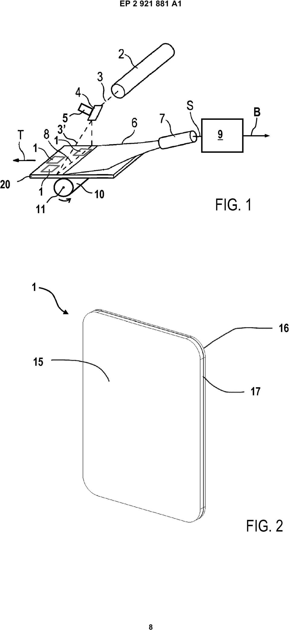
4 EP A1 6 become more apparent from the following detailed description of preferred embodiments with reference to the attached figures showing: Fig. 1 Fig. 2 Fig. 3 Fig. 4 Fig. a schematic representation of an example of a system for reading out X-ray information stored in storage phosphor plates; a perspective view of an example of a storage phosphor plate; a first perspective view of an example of a storage phosphor plate assembly; a second perspective view of an example of a storage phosphor plate assembly; and a front view of an example of a storage phosphor plate assembly. [0021] Fig. 1 shows schematic representation of an example of a system for reading out storage phosphor plates 1 provided on a support plate. The support plate comprises a, preferably rigid, base plate containing magnetic material, in particular ferromagnetic and/or ferrimagnetic material. The storage phosphor plates 1 contain permanent magnetic material causing magnetic attraction between the storage phosphor plates 1 and support plate. As a result, the storage phosphor plates 1 are detachably fixed on the support plate. By this means, the storages phosphor plates 1 are reliably fixed on the support plate during handling, in particular during reading out X-ray information stored in the storage phosphor layers 1, but can be easily, in particular manually, detached from the support plate after termination of the handling procedure. [0022] A transport device is provided for conveying the support plate together with the storage phosphor plates 1 provided thereon along a transport direction T. In the example shown, the transport device comprises a roller which rotated about a rotational axis 11 by a roller drive (not shown). The support plate is supported by the roller and, as a result of frictional engagement between the support plate and the roller, conveyed in direction T by a rotation of the roller. [0023] The roller contains magnetic, preferably permanently magnetic or electromagnetic, elements causing the roller to interact with the magnetic, in particular ferromagnetic and/or ferromagnetic, support plate so that the support plate is attracted by the roller. By this means, the frictional forces between the bottom face of the support plate and the roller are significantly enlarged so that a particularly reliable transport of the support plate and the storage phosphor plates 1 provided thereon is ensured. [0024] Preferably, on the roller at least one magnetic area is provided following a helical course. This embodiment is based on the approach of transporting the support plate by a, preferably single, roller having a magnetic area, whereby the magnetic area provided on the roller follows a helical course. Preferably, the term "helical course" is understood to be a course of the magnetic area in the form of a helical line, helix, coil or a so-called cylindrical spiral about the rotational axis 11 of the roller, the distance from the magnetic area to the rotational axis 11 being preferably constant, i.e. the helical course being circular in cross-section. Preferably, the term "magnetic area" is understood to be a permanent magnetic area which attracts ferromagnetic and/or ferrimagnetic objects by magnetic forces. The helically configured course of the magnetic area offers the advantage, compared to completely sheathing the roller with a magnetic layer, which however may also be a preferred embodiment, that during a complete rotation of the roller no abutting edges or overlapping, respectively, of the leading and trailing edge of the sheathing occur, thus ensuring a highly reliable, shock-free transport of the support plate. The absence of abutting edges or overlapping edges moreover allows preventing jumps in the magnetic field lines generated by the magnetic area during the rotation of the roller, which additionally contributes to a shock-free transport of the support plate. [002] Alternatively or additionally, one or more magnetic, preferably permanent magnetic, elements are arranged inside the roller which has the form of a hollow body, in particular a hollow cylinder. This embodiment is based on the approach of providing a hollow roller for transporting the support plate, whereby one or more magnets are arranged inside the hollow roller in such a way that during a rotation of the roller they maintain a predetermined spatial position and in particular do not follow the rotational movement of the roller. The hollow roller body itself is hereby not magnetic, in particular not ferromagnetic. A support plate being magnetic, in particular ferromagnetic and/or ferrimagnetic, at least in partial areas is attracted towards the hollow roller body by magnetic forces by the magnets arranged inside the hollow roller body in such a way that the frictional forces which occur when the support plate comes into contact with the hollow roller body are considerably increased compared to a roller with no additional magnets arranged in its inside. During a rotation of the roller the transport of the support plate contacting the roller is assured with increased reliability. [0026] Overall, the above elucidated embodiments provide the advantage of combining a straightforward structure and a reliable transport of the support plate. [0027] A laser 2 generates a stimulating light beam 3 that is deflected by a deflection element 4 in such a way that the deflected stimulating light 3 beam moves along a line 8 across the support plate. Preferably, the deflection element 4 comprises an oscillating mirror which is driven by drive means. Alternatively, the deflection element 4 may comprise a rotating polygon mirror driven by according drive means, e.g. a motor. [0028] Due to a simultaneous transport of the support 4

5 7 EP A1 8 plate in the transport direction T, the line 8 of the deflected stimulation light beam 3 successively crosses different linear areas of the support plate including storage phosphor plates 1 provided thereon. During the movement of the deflected stimulating light beam 3 across a storage phosphor plate 1, the storage phosphor plate 1 emits emission light depending on the X-ray information stored therein, which emission light is collected by an optical collection device 6, for example an optical fiber bundle, and detected by an optical detector 7, preferably a photomultiplier (PMT), and is thereby converted into a corresponding detector signal S. The detector signal S is transmitted to a processing device 9, in which digital image signal values B for individual pixels of the read out X-ray image are derived. As a result, a twodimensional X-ray image is obtained that is composed of individual pixels each associated with an image signal value B. [0029] Fig. 2 shows a prospective view of an example of a storage phosphor plate 1 comprising a storage phosphor layer 1 which is applied to a substrate layer 16, e.g. by an adhesive layer 17. [00] Preferably, the substrate layer 16 is made of or contains a permanent magnetic material, e.g. a material containing iron, nickel or cobalt. In particular, the substrate layer 16 contains a magnetically hard material, e.g. tempered steel and/or ferrite steel, exhibiting a high residual magnetic flux density, also referred to as remanence, and/or high coercivity, also referred to as coercive field strength. Preferably, the residual magnetic flux density of the magnetic material is higher than 10 mt, in particular higher than 0 mt. It is further preferred that the coercivity is higher than 0 ka/m, preferably higher than 10 ka/m. [0031] According to another preferred embodiment, the thickness of the substrate layers 16 is between 0, and 2 mm, in particular approximately 1 mm. It is, moreover, preferred, that the substrate layer 16 is a flexible layer. [0032] The storage phosphor plates 1 of the storage phosphor plate assembly may have a variety of different forms and/or dimensions. E.g., in the field of dental X- ray imaging, storage phosphor plates 1 typically have an essentially rectangular form with dimensions in the range between 2 and cm. In contrast to this, in the field of non-destructive testing, the storage phosphor plates 1 may be tailored in accordance with the particular object to be X-rayed. With the storage phosphor plate assembly according to the invention, storage phosphor plates 1 of different sizes and/or shapes, one the one hand, are reliably held on the support plate (see fig. 1) due to magnetic forces between the storage phosphor plates 1 and the support plate and, one the other hand, can be easily, preferably by hand, detached or removed from the support plate. [0033] As already described above, the support plate may be a rigid single plate made of a ferromagnetic and/or ferrimagnetic material, e.g. ferrite steel, but it may also have a more complex structure as will be apparent from further embodiments shown in fig. 3 and 4. [0034] Fig. 3 shows a first perspective view of an example of a storage phosphor plate assembly, wherein the support plate comprises a, preferably rigid, base plate 22 of a magnetic, in particular ferromagnetic and/or ferrimagnetic, material. On the upper side of the base plate 22 a frame 21 is provided, which subdivides the support plate into different partitions, which can be loaded by a number of storage phosphor plates 1 of different size and/or shape, as exemplarily shown by means of in total five different storage phosphor plates 1. [003] Preferably, frame 21 is manufactured separately from base plate 22 and is attached thereto, e.g. by laminating and/or gluing. Preferably, the frame 21 is made of plastics or metal. [0036] Fig. 4 shows a second prospective view of an example of a storage phosphor plate assembly. As apparent from this representation, at one edge of the base plate 22 protrusions 24 are provided. Preferably, at least one of the protrusions 24 is provided with information, e.g. a machine-readable bar code or a clear text, enabling an identification of the support plate and/ or relating to the dimensions and/or structure of the support plate. Besides, the above elucidations in connection with the embodiment shown in fig. 3 apply accordingly. [0037] Fig. shows a front view of a further example of a storage phosphor plate assembly. Similarly to the embodiments shown in fig. 3 and 4, the magnetic base plate 22 of the support plate is subdivided into several partitions which can be loaded with various storage phosphor plates 1. [0038] In addition to the storage phosphor plates 1 marking elements 2 to 28 may be provided on support plate for the purpose of adding information to, preferably each of, the storage phosphor plates 1. [0039] For example, the marking elements 2 to 28 may contain information by means of which a particular storage phosphor plate 1 or an X-ray image stored therein can be identified. E.g., information contained in the marking elements 2 to 27 may relate to a particular tooth "34", "46", "27k" or "23" an X-ray image of which is stored in the respective storage phosphor plate 1. Alternatively or additionally, the information contained in the marking elements 2 and 28 may relate to any other information to be added to the respective storage phosphor plate 1, e.g. the "name" of a patient of a consecutive number "no." of an X-ray. [00] Preferably, the marking elements 2 and 26 are configured so as to be attracted to the magnetic base plate 22 of the support plate by means of magnetic forces. To this purpose, the marking elements 2 and 26 comprise a top layer containing the information to be added and a bottom layer containing permanent magnetic material. Regarding the permanent magnetic bottom layer of the marking elements 2 and 26, the above elucidations with respect to substrate layer 16 of storage phosphor plate 1 shown in fig. 2 apply accordingly. As a result,
, and is thereby")
6 9 EP A1 marking elements 2 and 26 can be placed easily and reliably in proximity to the storage phosphor plate 1 to which respective information is to be added. Likewise, after the readout of the X-ray information stored in the storage phosphor plates 1, the marking elements 2 and 26 can be detached or removed easily, preferably by hand, from the base plate 22 of the support plate. [0041] According to another embodiment, marking elements 27 and 28 can be configured to be stuck or glued onto the storage phosphor plate 1 (see marking element 27) or onto an appropriate section of frame 21 (see marking element 28) in proximity to the phosphor plate 1 to which respective information is to be added. Preferably, the marking elements 27 and 28 comprise a top layer containing the information to be added and an adhesive bottom layer by which the top layer is affixed to the storage phosphor plate 1 or the respective section of frame 21, respectively. Preferably, the adhesive layer contains an adhesive allowing for an easy and residue-free detachment of the marking element 27 from the storage phosphor plate 1 or of the marking element 28 from frame 21, respectively. [0042] According to another preferred embodiment, the information contained in the marking elements 2 to 28 is represented or embodied by a fluorescent clear text and/or a fluorescent machine-readable code provided on the top layer of the marking elements 2 to 28. For example, the information "34" or "name" can be applied to marking element 2 by means of printing and/or handwriting using a fluorescent ink. [0043] Preferably, the fluorescent clear text or code is configured to be stimulable by the deflected laser beam 3 (see fig. 1) during the read-out process of the storage phosphor plates 1, whereby fluorescent light is emitted by the marking elements 2 to 28 and detected by detector 7. As a result, the finally obtained digital image of the storage phosphor assembly does not only contain the read out X-ray information stored in the storage phosphor plates 1, but also the additional information contained in the marking elements 2 to 28. In this way, a correct assignment of a read out X-ray image to the according case, e.g. a tooth, patient, work piece etc., is ensured with high reliability and is considerably simplified. [0044] In another preferred embodiment, the fluorescent code or clear text provided on the top layer of the marking elements 2 to 28 is not only machine-readable by the storage phosphor read-out device, but also human-readable. By this means, it can be easily ensured that the correct marking element 2 to 28 is chosen and placed in proximity to the according storage phosphor plate 1. Claims 1. A storage phosphor plate assembly (1, ) comprising at least one storage phosphor plate (1) comprising a storage phosphor layer (1) for storing X-ray information and a substrate layer (16) on which the storage phosphor layer (1) is provided, the substrate layer (16) containing a permanent magnetic material, and - a support plate (, 22) containing a magnetic material, the at least one storage phosphor plate (1) being held on the support plate (, 22) due to magnetic forces. 2. The storage phosphor plate assembly according to claim 1, the permanent magnetic material of the substrate layer (16) corresponding to a ferromagnetic material exhibiting high coercive field strength (bhc, ihc) and/or high remanence (Br). 3. The storage phosphor plate assembly according to claim 1 or 2, the substrate layer (16) being a flexible layer. 4. The storage phosphor plate assembly according to any of the preceding claims, the magnetic material of the support plate (, 22) corresponding to a ferromagnetic and/or ferrimagnetic material.. The storage phosphor plate assembly according to any of the preceding claims, the support plate (, 22) containing a layer of steel, in particular of ferrite steel. 6. The storage phosphor plate assembly according to any of the preceding claims, the support plate (, 22) being a rigid plate. 7. The storage phosphor plate assembly according to any of the preceding claims, the support plate (, 22) having a thickness of between 0 mm and 0 mm, in particular of approximately 0 mm. 8. The storage phosphor plate assembly according to any of the preceding claims, comprising at least one marking element (2-28), the at least one marking element (2-28) being - provided on the support plate (, 22) and/or on the storage phosphor plate (1) and - configured to identify the storage phosphor plate (1) and/or the X-ray information stored in the storage phosphor plate (1). 9. The storage phosphor plate assembly according to claim 8, the at least one marking element (2-28) containing a permanent magnetic material and being held on the support plate (, 22) due to magnetic forces.. The storage phosphor plate assembly according to 6
 or onto an appropriate section of")
7 11 EP A1 12 claim 8 or 9, the storage phosphor layer (1) being configured to emit emission light upon irradiation with stimulating light (3, 3, 8) and the at least one marking element (2-28) comprising a fluorescent material being configured to emit fluorescent light upon irradiation with the stimulating light (3, 3, 8). 11. An X-ray cassette comprising a housing in which the storage phosphor plate assembly (1, ) according to any of the preceding claims is accommodated. 12. A system for reading out X-ray information stored in storage phosphor plates (1), the system comprising - the storage phosphor plate assembly (1, ) according to any of the claims 1 to - a read-out device (2, 4-7, 9) configured to irradiate the at least one storage phosphor plate (1) being held on the support plate () with stimulating light (3, 3, 8) and to detect emission light which is stimulated in the at least one storage phosphor plate (1), and - a transport device () configured to transport the storage phosphor plate assembly (1, ) relative to the read-out device (2, 4-7, 9) The system according to claim 12, the transport device () comprising at least one magnetic, preferably permanent magnetic, element configured to couple to the support plate () by magnetic forces. 14. The system according to claim 13, the transport device () comprising at least one roller () configured to rotate about a rotational axis (11) of the at least one roller (), wherein the magnetic element is provided on the at least one roller () and/or inside of the roller () The system according to any of the claims 12 to 14, the read-out device (2, 4-7, 9) being configured to irradiate at least one marking element (2-28), which is provided on the support plate (, 22) and/or on the storage phosphor plate (1), with stimulating light (3, 3, 8) and to detect fluorescent light emitted by the marking element (2-28) upon irradiation with the stimulating light (3, 3, 8)
, the system comprising - the storage phosphor plate assembly (1, ) according to any of the claims 1 to - a read-out")
8 EP A1 8
9 EP A1 9

10 EP A1

11 EP A

12 EP A

TEPZZ 69 _ZA T EP 2 692 310 A2 (19) (11) EP 2 692 310 A2. (12) EUROPEAN PATENT APPLICATION published in accordance with Art.
 (11) EP 2 692 310 A2. (12) EUROPEAN PATENT APPLICATION published in accordance with Art.") (19) TEPZZ 69 _ZA T (11) EP 2 692 3 A2 (12) EUROPEAN PATENT APPLICATION published in accordance with Art. 13(4) EPC (43) Date of publication: 0.02.14 Bulletin 14/06 (21) Application number: 1276632.0 (22)
(19) TEPZZ 69 _ZA T (11) EP 2 692 3 A2 (12) EUROPEAN PATENT APPLICATION published in accordance with Art. 13(4) EPC (43) Date of publication: 0.02.14 Bulletin 14/06 (21) Application number: 1276632.0 (22)
TEPZZ 87_546A T EP 2 871 546 A2 (19) (11) EP 2 871 546 A2 (12) EUROPEAN PATENT APPLICATION. (51) Int Cl.: G05B 19/05 (2006.01)
 (11) EP 2 871 546 A2 (12) EUROPEAN PATENT APPLICATION. (51) Int Cl.: G05B 19/05 (2006.01)") (19) TEPZZ 87_46A T (11) EP 2 871 46 A2 (12) EUROPEAN PATENT APPLICATION (43) Date of publication: 13.0.1 Bulletin 1/ (1) Int Cl.: G0B 19/0 (06.01) (21) Application number: 14188238.1 (22) Date of filing:
(19) TEPZZ 87_46A T (11) EP 2 871 46 A2 (12) EUROPEAN PATENT APPLICATION (43) Date of publication: 13.0.1 Bulletin 1/ (1) Int Cl.: G0B 19/0 (06.01) (21) Application number: 14188238.1 (22) Date of filing:
TEPZZ 9 Z5A_T EP 2 922 305 A1 (19) (11) EP 2 922 305 A1. (12) EUROPEAN PATENT APPLICATION published in accordance with Art.
 (11) EP 2 922 305 A1. (12) EUROPEAN PATENT APPLICATION published in accordance with Art.") (19) TEPZZ 9 ZA_T (11) EP 2 922 A1 (12) EUROPEAN PATENT APPLICATION published in accordance with Art. 13(4) EPC (43) Date of publication: 23.09.1 Bulletin 1/39 (21) Application number: 1386446.2 (22) Date
(19) TEPZZ 9 ZA_T (11) EP 2 922 A1 (12) EUROPEAN PATENT APPLICATION published in accordance with Art. 13(4) EPC (43) Date of publication: 23.09.1 Bulletin 1/39 (21) Application number: 1386446.2 (22) Date
*EP001520563A1* EP 1 520 563 A1 (19) (11) EP 1 520 563 A1 (12) EUROPEAN PATENT APPLICATION. (43) Date of publication: 06.04.2005 Bulletin 2005/14
 (11) EP 1 520 563 A1 (12) EUROPEAN PATENT APPLICATION. (43) Date of publication: 06.04.2005 Bulletin 2005/14") (19) Europäisches Patentamt European Patent Office Office européen des brevets *EP001520563A1* (11) EP 1 520 563 A1 (12) EUROPEAN PATENT APPLICATION (43) Date of publication: 06.04.2005 Bulletin 2005/14
(19) Europäisches Patentamt European Patent Office Office européen des brevets *EP001520563A1* (11) EP 1 520 563 A1 (12) EUROPEAN PATENT APPLICATION (43) Date of publication: 06.04.2005 Bulletin 2005/14
TEPZZ 84 587A_T EP 2 843 587 A1 (19) (11) EP 2 843 587 A1 (12) EUROPEAN PATENT APPLICATION. (51) Int Cl.: G06F 21/64 (2013.01)
 (11) EP 2 843 587 A1 (12) EUROPEAN PATENT APPLICATION. (51) Int Cl.: G06F 21/64 (2013.01)") (19) TEPZZ 84 87A_T (11) EP 2 843 87 A1 (12) EUROPEAN PATENT APPLICATION (43) Date of publication: 04.03.201 Bulletin 201/ (1) Int Cl.: G06F 21/64 (2013.01) (21) Application number: 13181902.1 (22) Date
(19) TEPZZ 84 87A_T (11) EP 2 843 87 A1 (12) EUROPEAN PATENT APPLICATION (43) Date of publication: 04.03.201 Bulletin 201/ (1) Int Cl.: G06F 21/64 (2013.01) (21) Application number: 13181902.1 (22) Date
EP 2 455 926 A1 (19) (11) EP 2 455 926 A1 (12) EUROPEAN PATENT APPLICATION. (43) Date of publication: 23.05.2012 Bulletin 2012/21
 (11) EP 2 455 926 A1 (12) EUROPEAN PATENT APPLICATION. (43) Date of publication: 23.05.2012 Bulletin 2012/21") (19) (12) EUROPEAN PATENT APPLICATION (11) EP 2 4 926 A1 (43) Date of publication: 23.0.2012 Bulletin 2012/21 (21) Application number: 11190024.7 (1) Int Cl.: G08B 2/14 (2006.01) G08B 2/00 (2006.01) G0B
(19) (12) EUROPEAN PATENT APPLICATION (11) EP 2 4 926 A1 (43) Date of publication: 23.0.2012 Bulletin 2012/21 (21) Application number: 11190024.7 (1) Int Cl.: G08B 2/14 (2006.01) G08B 2/00 (2006.01) G0B
TEPZZ 68575_A_T EP 2 685 751 A1 (19) (11) EP 2 685 751 A1. (12) EUROPEAN PATENT APPLICATION published in accordance with Art.
 (11) EP 2 685 751 A1. (12) EUROPEAN PATENT APPLICATION published in accordance with Art.") (19) TEPZZ 687_A_T (11) EP 2 68 71 A1 (12) EUROPEAN PATENT APPLICATION published in accordance with Art. 3(4) EPC (43) Date of publication:.01.14 Bulletin 14/03 (21) Application number: 1278849.6 (22)
(19) TEPZZ 687_A_T (11) EP 2 68 71 A1 (12) EUROPEAN PATENT APPLICATION published in accordance with Art. 3(4) EPC (43) Date of publication:.01.14 Bulletin 14/03 (21) Application number: 1278849.6 (22)
TEPZZ 6_Z76 A_T EP 2 610 763 A1 (19) (11) EP 2 610 763 A1 (12) EUROPEAN PATENT APPLICATION. (51) Int Cl.:
 (11) EP 2 610 763 A1 (12) EUROPEAN PATENT APPLICATION. (51) Int Cl.:") (19) TEPZZ 6_Z76 A_T (11) EP 2 6 763 A1 (12) EUROPEAN PATENT APPLICATION (43) Date of publication: 03.07.2013 Bulletin 2013/27 (51) Int Cl.: G06F 17/30 (2006.01) (21) Application number: 12192220.7 (22)
(19) TEPZZ 6_Z76 A_T (11) EP 2 6 763 A1 (12) EUROPEAN PATENT APPLICATION (43) Date of publication: 03.07.2013 Bulletin 2013/27 (51) Int Cl.: G06F 17/30 (2006.01) (21) Application number: 12192220.7 (22)
TEPZZ 65Z79 A_T EP 2 650 793 A1 (19) (11) EP 2 650 793 A1. (12) EUROPEAN PATENT APPLICATION published in accordance with Art.
 (11) EP 2 650 793 A1. (12) EUROPEAN PATENT APPLICATION published in accordance with Art.") (19) TEPZZ 65Z79 A_T (11) EP 2 650 793 A1 (12) EUROPEAN PATENT APPLICATION published in accordance with Art. 153(4) EPC (43) Date of publication: 16.10.2013 Bulletin 2013/42 (21) Application number: 12818771.3
(19) TEPZZ 65Z79 A_T (11) EP 2 650 793 A1 (12) EUROPEAN PATENT APPLICATION published in accordance with Art. 153(4) EPC (43) Date of publication: 16.10.2013 Bulletin 2013/42 (21) Application number: 12818771.3
TEPZZ 8 8 A_T EP 2 811 282 A1 (19) (11) EP 2 811 282 A1 (12) EUROPEAN PATENT APPLICATION. (51) Int Cl.: G01N 3/04 (2006.01) G01N 3/08 (2006.
 (11) EP 2 811 282 A1 (12) EUROPEAN PATENT APPLICATION. (51) Int Cl.: G01N 3/04 (2006.01) G01N 3/08 (2006.") (19) TEPZZ 8 8 A_T (11) EP 2 811 282 A1 (12) EUROPEAN PATENT APPLICATION (43) Date of publication:.12.14 Bulletin 14/0 (1) Int Cl.: G01N 3/04 (06.01) G01N 3/08 (06.01) (21) Application number: 14170412.2
(19) TEPZZ 8 8 A_T (11) EP 2 811 282 A1 (12) EUROPEAN PATENT APPLICATION (43) Date of publication:.12.14 Bulletin 14/0 (1) Int Cl.: G01N 3/04 (06.01) G01N 3/08 (06.01) (21) Application number: 14170412.2
TEPZZ 799965A_T EP 2 799 965 A1 (19) (11) EP 2 799 965 A1. (12) EUROPEAN PATENT APPLICATION published in accordance with Art.
 (11) EP 2 799 965 A1. (12) EUROPEAN PATENT APPLICATION published in accordance with Art.") (19) TEPZZ 79996A_T (11) EP 2 799 96 A1 (12) EUROPEAN PATENT APPLICATION published in accordance with Art. 13(4) EPC (43) Date of publication: 0.11.14 Bulletin 14/4 (21) Application number: 14727698.4
(19) TEPZZ 79996A_T (11) EP 2 799 96 A1 (12) EUROPEAN PATENT APPLICATION published in accordance with Art. 13(4) EPC (43) Date of publication: 0.11.14 Bulletin 14/4 (21) Application number: 14727698.4
EP 2 365 669 A1 (19) (11) EP 2 365 669 A1 (12) EUROPEAN PATENT APPLICATION. (43) Date of publication: 14.09.2011 Bulletin 2011/37
 (11) EP 2 365 669 A1 (12) EUROPEAN PATENT APPLICATION. (43) Date of publication: 14.09.2011 Bulletin 2011/37") (19) (12) EUROPEAN PATENT APPLICATION (11) EP 2 36 669 A1 (43) Date of publication: 14.09.11 Bulletin 11/37 (1) Int Cl.: H04L 12/8 (06.01) (21) Application number: 00243.6 (22) Date of filing:.03. (84)
(19) (12) EUROPEAN PATENT APPLICATION (11) EP 2 36 669 A1 (43) Date of publication: 14.09.11 Bulletin 11/37 (1) Int Cl.: H04L 12/8 (06.01) (21) Application number: 00243.6 (22) Date of filing:.03. (84)
TEPZZ 8898 7A_T EP 2 889 827 A1 (19) (11) EP 2 889 827 A1 (12) EUROPEAN PATENT APPLICATION. (51) Int Cl.: G06Q 40/04 (2012.01)
 (11) EP 2 889 827 A1 (12) EUROPEAN PATENT APPLICATION. (51) Int Cl.: G06Q 40/04 (2012.01)") (19) TEPZZ 8898 7A_T (11) EP 2 889 827 A1 (12) EUROPEAN PATENT APPLICATION (43) Date of publication: 01.07.201 Bulletin 201/27 (1) Int Cl.: G06Q 40/04 (2012.01) (21) Application number: 14199864.1 (22)
(19) TEPZZ 8898 7A_T (11) EP 2 889 827 A1 (12) EUROPEAN PATENT APPLICATION (43) Date of publication: 01.07.201 Bulletin 201/27 (1) Int Cl.: G06Q 40/04 (2012.01) (21) Application number: 14199864.1 (22)
TEPZZ 69 49A_T EP 2 693 349 A1 (19) (11) EP 2 693 349 A1 (12) EUROPEAN PATENT APPLICATION. (51) Int Cl.: G06F 17/30 (2006.01)
 (11) EP 2 693 349 A1 (12) EUROPEAN PATENT APPLICATION. (51) Int Cl.: G06F 17/30 (2006.01)") (19) TEPZZ 69 49A_T (11) EP 2 693 349 A1 (12) EUROPEAN PATENT APPLICATION (43) Date of publication: 0.02.2014 Bulletin 2014/06 (1) Int Cl.: G06F 17/30 (2006.01) (21) Application number: 13160696.4 (22)
(19) TEPZZ 69 49A_T (11) EP 2 693 349 A1 (12) EUROPEAN PATENT APPLICATION (43) Date of publication: 0.02.2014 Bulletin 2014/06 (1) Int Cl.: G06F 17/30 (2006.01) (21) Application number: 13160696.4 (22)
EP 2 492 881 A2 (19) (11) EP 2 492 881 A2 (12) EUROPEAN PATENT APPLICATION. (43) Date of publication: 29.08.2012 Bulletin 2012/35
 (11) EP 2 492 881 A2 (12) EUROPEAN PATENT APPLICATION. (43) Date of publication: 29.08.2012 Bulletin 2012/35") (19) (12) EUROPEAN PATENT APPLICATION (11) EP 2 492 881 A2 (43) Date of publication: 29.08.2012 Bulletin 2012/35 (51) Int Cl.: G08B 13/16 (2006.01) G08B 25/08 (2006.01) (21) Application number: 12386006.6
(19) (12) EUROPEAN PATENT APPLICATION (11) EP 2 492 881 A2 (43) Date of publication: 29.08.2012 Bulletin 2012/35 (51) Int Cl.: G08B 13/16 (2006.01) G08B 25/08 (2006.01) (21) Application number: 12386006.6
TEPZZ 94Z968A_T EP 2 940 968 A1 (19) (11) EP 2 940 968 A1 (12) EUROPEAN PATENT APPLICATION. (51) Int Cl.: H04L 29/08 (2006.01)
 (11) EP 2 940 968 A1 (12) EUROPEAN PATENT APPLICATION. (51) Int Cl.: H04L 29/08 (2006.01)") (19) TEPZZ 94Z968A_T (11) EP 2 940 968 A1 (12) EUROPEAN PATENT APPLICATION (43) Date of publication: 04.11.20 Bulletin 20/4 (1) Int Cl.: H04L 29/08 (2006.01) (21) Application number: 1430649.7 (22) Date
(19) TEPZZ 94Z968A_T (11) EP 2 940 968 A1 (12) EUROPEAN PATENT APPLICATION (43) Date of publication: 04.11.20 Bulletin 20/4 (1) Int Cl.: H04L 29/08 (2006.01) (21) Application number: 1430649.7 (22) Date
TEPZZ 96 A_T EP 2 961 111 A1 (19) (11) EP 2 961 111 A1. (12) EUROPEAN PATENT APPLICATION published in accordance with Art.
 (11) EP 2 961 111 A1. (12) EUROPEAN PATENT APPLICATION published in accordance with Art.") (19) TEPZZ 96 A_T (11) EP 2 961 111 A1 (12) EUROPEAN PATENT APPLICATION published in accordance with Art. 13(4) EPC (43) Date of publication:.12.1 Bulletin 1/3 (21) Application number: 147426.7 (22) Date
(19) TEPZZ 96 A_T (11) EP 2 961 111 A1 (12) EUROPEAN PATENT APPLICATION published in accordance with Art. 13(4) EPC (43) Date of publication:.12.1 Bulletin 1/3 (21) Application number: 147426.7 (22) Date
Title (fr) SOURCE IONIQUE INTERNE DOUBLE POUR PRODUCTION DE FAISCEAU DE PARTICULES AVEC UN CYCLOTRON
 SOURCE IONIQUE INTERNE DOUBLE POUR PRODUCTION DE FAISCEAU DE PARTICULES AVEC UN CYCLOTRON") Title (en) A TWIN INTERNAL ION SOURCE FOR PARTICLE BEAM PRODUCTION WITH A CYCLOTRON Title (de) DOPPELTE INTERNE IONENQUELLE FÜR PARTIKELSTRAHLHERSTELLUNG MIT EINEM ZYKLOTRON Title (fr) SOURCE IONIQUE INTERNE
Title (en) A TWIN INTERNAL ION SOURCE FOR PARTICLE BEAM PRODUCTION WITH A CYCLOTRON Title (de) DOPPELTE INTERNE IONENQUELLE FÜR PARTIKELSTRAHLHERSTELLUNG MIT EINEM ZYKLOTRON Title (fr) SOURCE IONIQUE INTERNE
TEPZZ 87657ZA_T EP 2 876 570 A1 (19) (11) EP 2 876 570 A1 (12) EUROPEAN PATENT APPLICATION
 (11) EP 2 876 570 A1 (12) EUROPEAN PATENT APPLICATION") (19) TEPZZ 8767ZA_T (11) EP 2 876 70 A1 (12) EUROPEAN PATENT APPLICATION (43) Date of publication: 27.0.201 Bulletin 201/22 (21) Application number: 14189809.8 (1) Int Cl.: G06F 21/34 (2013.01) G08B 13/196
(19) TEPZZ 8767ZA_T (11) EP 2 876 70 A1 (12) EUROPEAN PATENT APPLICATION (43) Date of publication: 27.0.201 Bulletin 201/22 (21) Application number: 14189809.8 (1) Int Cl.: G06F 21/34 (2013.01) G08B 13/196
EP 2 354 708 A2 (19) (11) EP 2 354 708 A2 (12) EUROPEAN PATENT APPLICATION. (43) Date of publication: 10.08.2011 Bulletin 2011/32
 (11) EP 2 354 708 A2 (12) EUROPEAN PATENT APPLICATION. (43) Date of publication: 10.08.2011 Bulletin 2011/32") (19) (12) EUROPEAN PATENT APPLICATION (11) EP 2 354 708 A2 (43) Date of publication:.08.2011 Bulletin 2011/32 (51) Int Cl.: F24H 3/08 (2006.01) F24H 8/00 (2006.01) (21) Application number: 111536.8 (22)
(19) (12) EUROPEAN PATENT APPLICATION (11) EP 2 354 708 A2 (43) Date of publication:.08.2011 Bulletin 2011/32 (51) Int Cl.: F24H 3/08 (2006.01) F24H 8/00 (2006.01) (21) Application number: 111536.8 (22)
EUROPEAN PATENT APPLICATION. Hudson, NC 28638 (US) Chancery Lane London WC2A 1QU (GB)
 Chancery Lane London WC2A 1QU (GB)") (19) (12) Europaisches Patentamt European Patent Office Office europeen een des brevets EUROPEAN PATENT APPLICATION EP 0 889 344 A1 (43) Date of publication: (51) nt CI.6: G 02 B 6/44 07.01.1999 Bulletin
(19) (12) Europaisches Patentamt European Patent Office Office europeen een des brevets EUROPEAN PATENT APPLICATION EP 0 889 344 A1 (43) Date of publication: (51) nt CI.6: G 02 B 6/44 07.01.1999 Bulletin
Our patent and trade mark attorneys are here to help you protect and profit from your ideas, making sure they re working every bit as hard as you do.
 Our patent and trade mark attorneys are here to help you protect and profit from your ideas, making sure they re working every bit as hard as you do. Our people work with everyone from multi-nationals
EP 2 366 418 A2 (19) (11) EP 2 366 418 A2 (12) EUROPEAN PATENT APPLICATION. (43) Date of publication: 21.09.2011 Bulletin 2011/38
 (11) EP 2 366 418 A2 (12) EUROPEAN PATENT APPLICATION. (43) Date of publication: 21.09.2011 Bulletin 2011/38") (19) (12) EUROPEAN PATENT APPLICATION (11) EP 2 366 418 A2 (43) Date of publication: 21.09.2011 Bulletin 2011/38 (21) Application number: 11158108.8 (51) Int Cl.: A61M 5/36 (2006.01) A61M 5/315 (2006.01)
(19) (12) EUROPEAN PATENT APPLICATION (11) EP 2 366 418 A2 (43) Date of publication: 21.09.2011 Bulletin 2011/38 (21) Application number: 11158108.8 (51) Int Cl.: A61M 5/36 (2006.01) A61M 5/315 (2006.01)
(51) Int Cl.: H04N 7/52 (2011.01)
 Int Cl.: H04N 7/52 (2011.01)") (19) TEPZZ_9776 B_T (11) EP 1 977 611 B1 (12) EUROPEAN PATENT SPECIFICATION (4) Date of publication and mention of the grant of the patent: 16.01.13 Bulletin 13/03 (21) Application number: 0683819.1 (22)
(19) TEPZZ_9776 B_T (11) EP 1 977 611 B1 (12) EUROPEAN PATENT SPECIFICATION (4) Date of publication and mention of the grant of the patent: 16.01.13 Bulletin 13/03 (21) Application number: 0683819.1 (22)
EP 1 675 420 A1 (19) (11) EP 1 675 420 A1 (12) EUROPEAN PATENT APPLICATION. (43) Date of publication: 28.06.2006 Bulletin 2006/26
 (11) EP 1 675 420 A1 (12) EUROPEAN PATENT APPLICATION. (43) Date of publication: 28.06.2006 Bulletin 2006/26") (19) Europäisches Patentamt European Patent Office Office européen des brevets (12) EUROPEAN PATENT APPLICATION (11) EP 1 67 4 A1 (43) Date of publication: 28.06.06 Bulletin 06/26 (1) Int Cl.: H04Q 7/34
(19) Europäisches Patentamt European Patent Office Office européen des brevets (12) EUROPEAN PATENT APPLICATION (11) EP 1 67 4 A1 (43) Date of publication: 28.06.06 Bulletin 06/26 (1) Int Cl.: H04Q 7/34
TEPZZ 79ZZ8_A_T EP 2 790 081 A1 (19) (11) EP 2 790 081 A1 (12) EUROPEAN PATENT APPLICATION. (43) Date of publication: 15.10.2014 Bulletin 2014/42
 (11) EP 2 790 081 A1 (12) EUROPEAN PATENT APPLICATION. (43) Date of publication: 15.10.2014 Bulletin 2014/42") (19) TEPZZ 79ZZ8_A_T (11) EP 2 790 081 A1 (12) EUROPEAN PATENT APPLICATION (43) Date of publication: 1..14 Bulletin 14/42 (1) Int Cl.: G0D 23/19 (06.01) (21) Application number: 1414221.7 (22) Date of
(19) TEPZZ 79ZZ8_A_T (11) EP 2 790 081 A1 (12) EUROPEAN PATENT APPLICATION (43) Date of publication: 1..14 Bulletin 14/42 (1) Int Cl.: G0D 23/19 (06.01) (21) Application number: 1414221.7 (22) Date of
 HU CZ FI PL SI PT IT ES NO NL FR DK SE IE GB AT DE CH LU 0 10 20 30 40 Foreigners' share Source: Eurostat More trust 3 4 5 6 7 PL HU CZ SI PT GR ES DK FI SE
(51) Int Cl.: H04L 12/58 (2006.01) H04L 29/06 (2006.01)
 Int Cl.: H04L 12/58 (2006.01) H04L 29/06 (2006.01)") (19) TEPZZ_986 8 B_T (11) EP 1 986 382 B1 (12) EUROPEAN PATENT SPECIFICATION (4) Date of publication and mention of the grant of the patent: 19.02.14 Bulletin 14/08 (1) Int Cl.: H04L 12/8 (06.01) H04L
(19) TEPZZ_986 8 B_T (11) EP 1 986 382 B1 (12) EUROPEAN PATENT SPECIFICATION (4) Date of publication and mention of the grant of the patent: 19.02.14 Bulletin 14/08 (1) Int Cl.: H04L 12/8 (06.01) H04L
The EU Energy Tax Directive: overview about the proposed reform, impacts on national measures and state of play
 Environmentally Related Taxes and Fiscal Reform Rome, Thursday, 15 December 2011 The EU Energy Tax Directive: overview about the proposed reform, impacts on national measures and state of play A short
(51) Int Cl.: G06F 9/455 (2006.01) G06F 9/50 (2006.01)
 Int Cl.: G06F 9/455 (2006.01) G06F 9/50 (2006.01)") (19) TEPZZ 6987 B_T (11) EP 2 698 711 B1 (12) EUROPEAN PATENT SPECIFICATION (4) Date of publication and mention of the grant of the patent: 0.08.1 Bulletin 1/32 (21) Application number: 118777.8 (22) Date
(19) TEPZZ 6987 B_T (11) EP 2 698 711 B1 (12) EUROPEAN PATENT SPECIFICATION (4) Date of publication and mention of the grant of the patent: 0.08.1 Bulletin 1/32 (21) Application number: 118777.8 (22) Date
TEPZZ 88_898A_T EP 2 881 898 A1 (19) (11) EP 2 881 898 A1 (12) EUROPEAN PATENT APPLICATION. (51) Int Cl.: G06N 5/04 (2006.01) G06F 17/30 (2006.
 (11) EP 2 881 898 A1 (12) EUROPEAN PATENT APPLICATION. (51) Int Cl.: G06N 5/04 (2006.01) G06F 17/30 (2006.") (19) TEPZZ 88_898A_T (11) EP 2 881 898 A1 (12) EUROPEAN PATENT APPLICATION (43) Date of publication:.06. Bulletin /24 (1) Int Cl.: G06N /04 (06.01) G06F 17/ (06.01) (21) Application number: 136680.3 (22)
(19) TEPZZ 88_898A_T (11) EP 2 881 898 A1 (12) EUROPEAN PATENT APPLICATION (43) Date of publication:.06. Bulletin /24 (1) Int Cl.: G06N /04 (06.01) G06F 17/ (06.01) (21) Application number: 136680.3 (22)
Doro PhoneEasy 331ph
 Doro PhoneEasy 331ph 1 2 6 3 4 5 English 1 Ringer indicator 2 Hanging Hook for Handset 3 Redial function 4 Volume control 5 Flash button/programming 6 Speed dial memories This device is intended for the
The Methodology of Projection Television Systems
 J Europaisches Patentamt European Patent Office Office europeen des brevets GO Publication number: 0 408 113 A1 EUROPEAN PATENT APPLICATION Application number: 90201785.4 @ Date of filing: 05.07.90 int.
TEPZZ 9 8Z87A_T EP 2 938 087 A1 (19) (11) EP 2 938 087 A1 (12) EUROPEAN PATENT APPLICATION
 (11) EP 2 938 087 A1 (12) EUROPEAN PATENT APPLICATION") (19) TEPZZ 9 8Z87A_T (11) EP 2 938 087 A1 (12) EUROPEAN PATENT APPLICATION (43) Date of publication: 28..1 Bulletin 1/44 (21) Application number: 14604.2 (1) Int Cl.: H04N 21/23 (11.01) H04N 21/488 (11.01)
(19) TEPZZ 9 8Z87A_T (11) EP 2 938 087 A1 (12) EUROPEAN PATENT APPLICATION (43) Date of publication: 28..1 Bulletin 1/44 (21) Application number: 14604.2 (1) Int Cl.: H04N 21/23 (11.01) H04N 21/488 (11.01)
The EU s 2030 Effort Sharing Agreement
 The EU s 2030 Effort Sharing Agreement Brussels CEPS Workshop, 29.06.2015 Oliver Sartor, oliver.sartor@iddri.org Research Fellow, Climate & Energy Policy, IDDRI Celine MARCY, IDDRI Institute for Sustainable
A Practical Guide to Free Energy Devices
 A Practical Guide to Free Energy Devices Electrolysis Patents No 14: Last updated: 28th January 2006 Author: Patrick J. Kelly Please note that this is a re-worded excerpt from this patent. If the content
egovernment Digital Agenda Scoreboard 2014
 egovernment Digital Agenda Scoreboard 2014 1 egovernment use in EU28 has been flat In 2013 egovernment services have been used by 41% of the EU28 population, down from 44% in 2012 and almost at the same
CO2 BASED MOTOR VEHICLE TAXES IN THE EU IN 2015
 CO2 BASED MOTOR VEHICLE TAXES IN THE EU IN 2015 COUNTRY AT (AUSTRIA) BE (BELGIUM) BG (BULGARIA) CO2/FUEL CONSUMPTION TAXES A fuel consumption tax (Normverbrauchsabgabe or NoVA) is levied upon the first
European Research Council
 ERC Starting Grant Outcome: Indicative statistics Reproduction is authorised provided the source ERC is acknowledged ERCEA/JH. ERC Starting Grant: call Submitted and selected proposals by domain Submitted
UNITED STATES PATENT AND TRADEMARK OFFICE BEFORE THE BOARD OF PATENT APPEALS AND INTERFERENCES
 UNITED STATES PATENT AND TRADEMARK OFFICE BEFORE THE BOARD OF PATENT APPEALS AND INTERFERENCES Ex parte HUBERTUS BUTTNER, MARCUS VAN HEYDEN, MARKUS DEUTEL, and ALFONS VOLLMUTH Appeal 2009-002387 1 Technology
ENTERING THE EU BORDERS & VISAS THE SCHENGEN AREA OF FREE MOVEMENT. EU Schengen States. Non-Schengen EU States. Non-EU Schengen States.
 ENTERING THE EU BORDERS & VISAS THE SCHENGEN AREA OF FREE MOVEMENT An area without internal borders where EU citizens and non-eu nationals may move freely EU Schengen States Non-Schengen EU States IS Azores
Your first EURES job. Progress Summary 2014Q4. March 2015
 Progress Summary 04Q4 March 05 This summary presents an overview of the implementation of Your first Eures job since the start date of activities in June 0 until the end of 04. It highlights in particular
MM, EFES EN. Marc Mathieu
 MM, EFES EN Marc Mathieu La Tribune Hewitt EUROPEAN EMPLOYEE OWNERSHIP ACROSS THE CRISIS Numbers 2006/2007/2008/2009 2009 2008 2007 2006 Employee owners 9.3 million 9.0 million 8.4 million Employees' share
sparktable: Generating Graphical Tables for Websites and Documents with R
 Alexander Kowarik 1, Bernhard Meindl 1 and Matthias Templ 1,2 1. Statistics Austria 2. Vienna University of Technology Q Vienna, June, 2014 sparktable: Generating Graphical Tables for Websites and Documents
*EP001173363B1* EP 1 173 363 B1 (19) (11) EP 1 173 363 B1 (12) EUROPEAN PATENT SPECIFICATION
 (11) EP 1 173 363 B1 (12) EUROPEAN PATENT SPECIFICATION") (19) Europäisches Patentamt European Patent Office Office européen des brevets *EP001173363B1* (11) EP 1 173 363 B1 (12) EUROPEAN PATENT SPECIFICATION (4) Date of publication and mention of the grant of
(19) Europäisches Patentamt European Patent Office Office européen des brevets *EP001173363B1* (11) EP 1 173 363 B1 (12) EUROPEAN PATENT SPECIFICATION (4) Date of publication and mention of the grant of
Permanent Magnetic Couplings and Brakes for Drive Technology
 Tridelta Magnetsysteme A Tridelta Group Company Permanent Magnetic Couplings and Brakes for Drive Technology Raw Materials Magnets Systems and Components Magnet N1 Soft iron N2 Resin Introduction and principals
OHIM SEARCH TOOLS: TMVIEW, DSVIEW AND TMCLASS. Making trade mark and design information readily available for users
 OHIM SEARCH TOOLS: TMVIEW, DSVIEW AND TMCLASS Making trade mark and design information readily available for users Mariano Riccheri Moscow, 24 September 2015 INTERNATIONAL COOPERATION AREA European Cooperation:
Finnish foreign trade 2014 Figures and diagrams. 27.2.2015 FINNISH CUSTOMS Statistics 1
 Finnish foreign trade 214 Figures and diagrams 27.2.215 FINNISH CUSTOMS Statistics 1 IMPORTS, EXPORTS AND TRADE BALANCE 199-214 7 billion e 6 5 4 3 2 1-1 9 91 92 93 94 95 96 97 98 99 1 2 3 4 5 6 7 8 9
AGRICULTURAL COVERING
 1 AGRICULTURAL COVERING Patent number: US2015064415 Date of publication: 2015-03-05 Applicant(s): BEAULIEU TECHNICAL TEXTILES (BE) The present invention is directed to an agricultural covering in form
SURVEY ON THE TRAINING OF GENERAL CARE NURSES IN THE EUROPEAN UNION. The current minimum training requirements for general care nurses
 SURVEY ON THE TRAINING OF GENERAL CARE NURSES IN THE EUROPEAN UNION This survey serves as a background document for the discussion of the Commission's legislative proposal to modernize the minimum requirements
Centripetal force, rotary motion, angular velocity, apparent force.
 Related Topics Centripetal force, rotary motion, angular velocity, apparent force. Principle and Task A body with variable mass moves on a circular path with ad-justable radius and variable angular velocity.
(72) Inventors: Juergen RIEDL, Koenigsbrunn (DE); USPC ( 267/285)
 Inventors: Juergen RIEDL, Koenigsbrunn (DE); USPC ( 267/285)") US 20130087957A1 (19) United States (12) Patent Application Publication (10) Pub. No.: US 2013/0087957 A1 RIEDL et al. (43) Pub. Date: Apr. 11, 2013 (54) DEVICE FOR DAMPING THE VIBRATIONS Publication Classi?cation
US 20130087957A1 (19) United States (12) Patent Application Publication (10) Pub. No.: US 2013/0087957 A1 RIEDL et al. (43) Pub. Date: Apr. 11, 2013 (54) DEVICE FOR DAMPING THE VIBRATIONS Publication Classi?cation
ASUS Transformer Pad QSG TF300TG 3G Connection Manager
 E7210 QSG TF300TG 3G Connection Manager Installing SIM card 1. Use a straightened paper clip to press the SIM card tray eject button. 2. Remove the tray from the slot. Orient and place the SIM card on
DHL Door-To-More UNLOCKING THE POTENTIAL OF DIRECT DISTRIBUTION
 DHL Door-To-More UNLOCKING THE POTENTIAL OF DIRECT DISTRIBUTION 2 DHL Door-To-More TM DHL Door-To-More 3 DHL DOOR-TO-MORE The seamless intercontinental door-to-door distribution solution that delivers
European Research Council
 ERC Advanced Grants 2011 Outcome: Indicative Statistics Reproduction is authorised provided that the source ERC is acknowledged NB: In these graphs grantee refers to a candidate selected for ERC funding
KNOWLEDGE ECONOMY CHALLENGES FOR LIFEONG LEARNING
 KNOWLEDGE ECONOMY CHALLENGES FOR LIFEONG LEARNING Anna Kaderabkova, Centre for Economic Studies, Prague www.cesvsem.cz 10. 11. 2006, Prague 1 Structure: 1. Innovation-driven demand for skills in enterprises
ZTE Blade V Quick Start Guide
 ZTE Blade V Quick Start Guide LEGAL INFORMATION Copyright 2013 ZTE CORPORATION. All rights reserved. No part of this publication may be quoted, reproduced, translated or used in any form or by any means,
The case for a European Social Union. From muddling through to a sense of common purpose. Frank Vandenbroucke EIB Institute Luxembourg, 5 March 2015
 The case for a European Social Union. From muddling through to a sense of common purpose. Frank Vandenbroucke EIB Institute Luxembourg, 5 March 2015 A European Social Union A Social Union would support
(12) Oversettelse av europeisk patentskrift
 Oversettelse av europeisk patentskrift") (12) Oversettelse av europeisk patentskrift (11) NO/EP 2294743 B1 (19) NO NORGE (51) Int Cl. H04L 1/16 (2006.01) H04L 1/18 (2006.01) Patentstyret (21) Oversettelse publisert 2012.12.10 (80) Dato for Den
(12) Oversettelse av europeisk patentskrift (11) NO/EP 2294743 B1 (19) NO NORGE (51) Int Cl. H04L 1/16 (2006.01) H04L 1/18 (2006.01) Patentstyret (21) Oversettelse publisert 2012.12.10 (80) Dato for Den
(51) Int Cl.: G06F 11/14 (2006.01)
 Int Cl.: G06F 11/14 (2006.01)") (19) (12) EUROPEAN PATENT SPECIFICATION (11) EP 1 08 414 B1 (4) Date of publication and mention of the grant of the patent: 04.03.09 Bulletin 09/ (1) Int Cl.: G06F 11/14 (06.01) (21) Application number:
(19) (12) EUROPEAN PATENT SPECIFICATION (11) EP 1 08 414 B1 (4) Date of publication and mention of the grant of the patent: 04.03.09 Bulletin 09/ (1) Int Cl.: G06F 11/14 (06.01) (21) Application number:
Czech Universities and the Environment for Innovation. Rudolf Hanka
 Czech Universities and the Environment for Innovation Rudolf Hanka Czech Republic a cauldron of Central Europe? Geographical position Major motorways High speed backbone network Czech internet network
GUIDANCE for Administration of the Sunset Clause
 GUIDANCE Edition number : 02 Edition date: 16/07/2010 Implementation date : 28/12/2007 CMDv Secretariat: 7 Westferry Circus, Canary Wharf, London, E14 4HB, UK CMDv/TEM/013-00 Tel. (44-20) 74 18 84 00 Fax.
EN 106 EN 4. THE MOBILE USE OF THE INTERNET BY INDIVIDUALS AND ENTERPRISES. 4.1. Introduction
 4. THE MOBILE USE OF THE INTERNET BY INDIVIDUALS AND ENTERPRISES 4.1. Introduction This chapter looks at mobile use of the internet by individuals and enterprises, benefiting from new data collected in
US 20060209260A1 (19) United States (12) Patent Application Publication (10) Pub. No.: US 2006/0209260 A1 Clegg (43) Pub. Date: Sep.
 United States (12) Patent Application Publication (10) Pub. No.: US 2006/0209260 A1 Clegg (43) Pub. Date: Sep.") US 20060209260A1 (19) United States (12) Patent Application Publication (10) Pub. No.: Clegg (43) Pub. Date: Sep. 21, 2006 (54) SCROLLING PICTURE CHANGER (52) US. Cl...... 352/98 (76) Inventor: Timothy
US 20060209260A1 (19) United States (12) Patent Application Publication (10) Pub. No.: Clegg (43) Pub. Date: Sep. 21, 2006 (54) SCROLLING PICTURE CHANGER (52) US. Cl...... 352/98 (76) Inventor: Timothy
Synthetic Sensing: Proximity / Distance Sensors
 Synthetic Sensing: Proximity / Distance Sensors MediaRobotics Lab, February 2010 Proximity detection is dependent on the object of interest. One size does not fit all For non-contact distance measurement,
ERMInE Database. Presentation by Nils Flatabø SINTEF Energy Research. ERMInE Workshop 2 - Northern Europe Oslo, 1. November 2006
 ERMInE Database Presentation by Nils Flatabø SINTEF Energy Research ERMInE Workshop 2 - Northern Europe Oslo, 1. November 26 Overview Content of the Ermine Database Electronic Questionnaire RTD&D Data
*EP001139245A1* EP 1 139 245 A1 (19) (11) EP 1 139 245 A1 (12) EUROPEAN PATENT APPLICATION. (43) Date of publication: 04.10.2001 Bulletin 2001/40
 (11) EP 1 139 245 A1 (12) EUROPEAN PATENT APPLICATION. (43) Date of publication: 04.10.2001 Bulletin 2001/40") (19) Europäisches Patentamt European Patent Office Office européen des brevets *EP00113924A1* (11) EP 1 139 24 A1 (12) EUROPEAN PATENT APPLICATION (43) Date of publication: 04..01 Bulletin 01/ (1) Int
(19) Europäisches Patentamt European Patent Office Office européen des brevets *EP00113924A1* (11) EP 1 139 24 A1 (12) EUROPEAN PATENT APPLICATION (43) Date of publication: 04..01 Bulletin 01/ (1) Int
Insertion Devices Lecture 4 Permanent Magnet Undulators. Jim Clarke ASTeC Daresbury Laboratory
 Insertion Devices Lecture 4 Permanent Magnet Undulators Jim Clarke ASTeC Daresbury Laboratory Introduction to Lecture 4 So far we have discussed at length what the properties of SR are, when it is generated,
European developments in VET Quality Assurance
 Sophie Weisswange DGVT meeting European developments in VET Quality Assurance Dublin 22-23 May 2013 EQAVET EQAVET list of indicators Underlying objectives: Better employability Better match between training
2015 Half Year Results Conference Call Presentation. 26 August 2015
 2015 Half Year Results Conference Call Presentation 26 August 2015 1 Today s Call Participants Dr Patrik De Haes - CEO Dominique Vanfleteren CFO 2 Agenda for the Call 2015 Highlights US update : objectives
(51) Int Cl.: B29C 41/20 (2006.01) F21S 4/00 (2006.01) H05K 3/28 (2006.01)
 Int Cl.: B29C 41/20 (2006.01) F21S 4/00 (2006.01) H05K 3/28 (2006.01)") (19) TEPZZ 68698B_T (11) EP 2 68 698 B1 (12) EUROPEAN PATENT SPECIFICATION (4) Date of publication and mention of the grant of the patent: 18.11.201 Bulletin 201/47 (21) Application number: 11808612.3
(19) TEPZZ 68698B_T (11) EP 2 68 698 B1 (12) EUROPEAN PATENT SPECIFICATION (4) Date of publication and mention of the grant of the patent: 18.11.201 Bulletin 201/47 (21) Application number: 11808612.3
RL HW / RL HW+ / RL HGW / RL HV / RL HVPW/RL HVPW-G
 Auto-Levelling Rotary Laser Level RL HW / RL HW+ / RL HGW / RL HV / RL HVPW/RL HVPW-G 77-496 / 77-429 / 77-439 / 77-497 / 77-427/ 77-441 Please read these instructions before operating the product Auto-Levelling
CL90i. 77-021 Please read these instructions before operating the product. 3 - Beam Self-Leveling Cross Line Laser
 3 - Beam Self-Leveling Cross Line Laser CL90i 77-01 Please read these instructions before operating the product Self-Leveling GB D F I E PT NL DK SE FIN NO PL GR CZ RU HU SK SI BG RO EE LV LT Contents
Europaisches Patentamt European Patent Office. 0 268 313 Office europeen des brevets. Publication number: EUROPEAN PATENT APPLICATION
 Europaisches Patentamt J ) European Patent Office Publication number: 0 268 313 Office europeen des brevets A1 EUROPEAN PATENT APPLICATION Application number: 87202023.5 int. cia D03D 47/36, B65H 51/20
A METHOD OF CALIBRATING HELMHOLTZ COILS FOR THE MEASUREMENT OF PERMANENT MAGNETS
 A METHOD OF CALIBRATING HELMHOLTZ COILS FOR THE MEASUREMENT OF PERMANENT MAGNETS Joseph J. Stupak Jr, Oersted Technology Tualatin, Oregon (reprinted from IMCSD 24th Annual Proceedings 1995) ABSTRACT The
OVERVIEW OF PURCHASE AND TAX INCENTIVES FOR ELECTRIC VEHICLES IN THE EU
 01.04.2014 OVERVIEW OF PURCHASE AND TAX INCENTIVES FOR ELECTRIC VEHICLES IN THE EU This table provides an overview of the incentives that are granted in the Member States of the European Union for the
A Practical Guide to Free Energy Devices
 A Practical Guide to Free Energy Devices Part PatD9: Last updated: 28th January 2006 Author: Patrick J. Kelly Please note that this is a re-worded excerpt from this patent. If the content interests you,
Page: 1 of 6 Page: 1 of 6
 Page: 1 of 6 Page: 1 of 6 CR Basics and FAQ Overview Computed Radiography is a term used to describe a system that electronically records a radiographic image. Computed Radiographic systems use unique
Common Communication on the Common Practice on the General Indications of the Nice Class Headings v1.1, 20 February 2014
 Common Communication on the Common Practice on the General Indications of the Nice Class Headings v1.1, 1 20 February 2014 On 19/06/2012 the Court delivered its ruling in Case C-307/10 "IP Translator",
The Transition to Tendering Perspective from the Manufacturing Industry
 The Transition to Tendering Perspective from the Manufacturing Industry Johannes Schiel, VDMA Power Systems Berlin, 12.11.2015 Lessons from Denmark Agora Event 2: Towards a Renewable Future - Energy Scenarios,
Dublin, March 2013. EPSO Network of Experts in the field of Personnel Selection 14th March 2013
 Dublin, March 2013 EPSO Network of Experts in the field of Personnel Selection 14th March 2013 On-going and upcoming competitions AD2012 by Citizenship AD2012 Citizenship %EU Population validated application
(54) (71) (72) Vedelago (TV) (IT) (73) (21) (22) (30) Chirignago (VE) (IT); Alberto Al?er, Foreign Application Priority Data
 (71) (72) Vedelago (TV) (IT) (73) (21) (22) (30) Chirignago (VE) (IT); Alberto Al?er, Foreign Application Priority Data") US 20130094227Al (19) United States (12) Patent Application Publication (10) Pub. No.: US 2013/0094227 A1 Scordino et al. (43) Pub. Date: Apr. 18, 2013 (54) (71) (72) (73) (21) (22) (30) MOUNTING DEVICE
US 20130094227Al (19) United States (12) Patent Application Publication (10) Pub. No.: US 2013/0094227 A1 Scordino et al. (43) Pub. Date: Apr. 18, 2013 (54) (71) (72) (73) (21) (22) (30) MOUNTING DEVICE
Social dumping and free movement: Overview of current issues from an economic point of view
 Social dumping and free movement: Overview of current issues from an economic point of view Prof. dr. Jozef Pacolet & Frederic De Wispelaere Design Charles & Ray Eames - Hang it all Vitra Statistics on
I have asked for asylum in the EU which country will handle my claim?
 EN I have asked for asylum in the EU which country will handle my claim? A Information about the Dublin Regulation for applicants for international protection pursuant to article 4 of Regulation (EU) No
ASUS Tablet. User Guide
 ASUS Tablet User Guide E9131 E8989 First Edition / August 2014 Charging your device Ensure to fully charge your ASUS Tablet before using it in battery mode for extended periods. Remember that the power
Active noise control in practice: transformer station
 Active noise control in practice: transformer station Edwin Buikema 1 ; Fokke D. van der Ploeg 2 ; Jan H. Granneman 3 1, 2, 3 Peutz bv, Netherlands ABSTRACT Based on literature and extensive measurements
CHAPTER 4 DESIGN OF INTEGRAL SLOT AND FRACTIONAL SLOT BRUSHLESS DC MOTOR
 47 CHAPTER 4 DESIGN OF INTEGRAL SLOT AND FRACTIONAL SLOT BRUSHLESS DC MOTOR 4.1 INTRODUCTION This chapter deals with the design of 24 slots 8 poles, 48 slots 16 poles and 60 slots 16 poles brushless dc
(12) (10) Patent N0.: US 6,740,055 B2 Dominguez (45) Date of Patent: May 25, 2004
 (10) Patent N0.: US 6,740,055 B2 Dominguez (45) Date of Patent: May 25, 2004") United States Patent US006740055B2 (12) (10) Patent N0.: US 6,740,055 B2 Dominguez (45) Date of Patent: May 25, 2004 (54) TRAUMA CERVICAL COLLAR 5,016,623 A * 5/1991 Krahenbuhl..... 602/27 5,054,475 A
United States Patent US006740055B2 (12) (10) Patent N0.: US 6,740,055 B2 Dominguez (45) Date of Patent: May 25, 2004 (54) TRAUMA CERVICAL COLLAR 5,016,623 A * 5/1991 Krahenbuhl..... 602/27 5,054,475 A
Physics 41, Winter 1998 Lab 1 - The Current Balance. Theory
 Physics 41, Winter 1998 Lab 1 - The Current Balance Theory Consider a point at a perpendicular distance d from a long straight wire carrying a current I as shown in figure 1. If the wire is very long compared
Data transport in radio astronomy. Arpad Szomoru, JIVE
 Data transport in radio astronomy Arpad Szomoru, JIVE Some acronyms EVN: European VLBI Network Consortium of radio telescopes Involving 14 different organizations around the world: Europe, China, Puerto
11. NONDESTRUCTIVE TESTING
 11. NONDESTRUCTIVE TESTING Nondestructive testing includes magnetic particle testing (MT), Liquid Dye Penetrant testing (PT), Radiographic Testing (RT) and Ultrasonic Testing (UT). The purpose of nondestructive
PERMAGRAPH L. for the computer controlled measurement of hysteresis curves of hard magnetic materials. www.magnet-physik.de. Introduction.
 Page 1 / 12 PERMAGRAPH L for the computer controlled measurement of hysteresis curves of hard magnetic materials Introduction The PERMAGRAPH is the world-wide known standard equipment for the measurement
Measuring Quality of life in the European Union
 Measuring Quality of life in Georgiana Ivan, European Commission European context of measuring Quality of Life Indicators Consistency with theory SSF Report The Triangle for Quality of Indicators Europe
ROUNDO 3-Roll Plate Bending Machines Type PS
 ROUNDO 3-Roll Plate Bending Machines Type PS Universal Machine used for all Plate Bending Double Pinch Design 1. Align the plate using the alignment grooves in the lower rolls or against the rear roll.
Step 11 Static Load Testing
 Step 11 Static Load Testing Test loading is the most definitive method of determining load capacity of a pile. Testing a pile to failure provides valuable information to the design engineer and is recommended
Guide to Magnetic Materials
 Guide to Magnetic s Abstract The purpose of this guide is to present the various materials and their performance, and also to give you the basic knowledge in choosing the right magnet material for your
Modeling Curved Surfaces
 Modeling Cylindrical and Curved Theory Views of Cylinders Contour Lines Extruded Surfaces Revolved Surfaces & Cutouts Profile Shape Axis of Revolution Swept Surfaces & Cutouts Profile Shape Path Curves
Chapter 3 SYSTEM SCANNING HARDWARE OVERVIEW
 Qiang Lu Chapter 3. System Scanning Hardware Overview 79 Chapter 3 SYSTEM SCANNING HARDWARE OVERVIEW Since all the image data need in this research were collected from the highly modified AS&E 101ZZ system,
February 2015. Euro-PCT applications: Claim amendment and other issues
 February 2015 Euro-PCT applications: Claim amendment and other issues February 2015 Issues arising when PCT applications enter the regional phase in the EPO Recent years have seen numerous changes to the
Economic Mass Producible Mirror Panels for Solar Concentrators
 Abstract G, G. Burgess, K. Lovegrove and A. Luzzi Centre for Sustainable Energy Systems Australian National University, Canberra 2 Australia E-mail: Glen@faceng.anu.edu.au The Centre for Sustainable Energy