(51) Int Cl.: G06F 11/14 ( )
|
|
|
- Moses Howard
- 8 years ago
- Views:
Transcription
1 (19) (12) EUROPEAN PATENT SPECIFICATION (11) EP B1 (4) Date of publication and mention of the grant of the patent: Bulletin 09/ (1) Int Cl.: G06F 11/14 (06.01) (21) Application number: (22) Date of filing: (4) Data migration method and apparatus using storage area network (SAN) Verfahren und Vorrichtung zur Datenmigration mit Speicherbereichnetz (SAN) Méthode et dispositif de migration de données utilisant un réseau à zone de mémoire (SAN) (84) Designated Contracting States: DE FR GB () Priority: JP (43) Date of publication of application: Bulletin 01/12 (73) Proprietor: Hitachi, Ltd. Chiyoda-ku Tokyo 1-80 (JP) (72) Inventor: Obara, Kiyohiro, c/o Hitachi, Ltd. Tokyo 0-82 (JP) (74) Representative: Strehl Schübel-Hopf & Partner Maximilianstrasse München (DE) (6) References cited: EP-A EP-A EP-A WO-A-99/198 EP B1 Note: Within nine months of the publication of the mention of the grant of the European patent in the European Patent Bulletin, any person may give notice to the European Patent Office of opposition to that patent, in accordance with the Implementing Regulations. Notice of opposition shall not be deemed to have been filed until the opposition fee has been paid. (Art. 99(1) European Patent Convention). Printed by Jouve, 7001 PARIS (FR)
 (84) Designated Contracting States: DE FR GB () Priority: 07.09.1999 JP 262999 (43) Date of publication of application: 21.03.")
2 Description BACKGROUND OF THE INVENTION 3 FIELD OF THE INVENTION [0001] The present invention relates to a method of data backup for a storage system via a Storage Area Network (SAN), and is especially applicable to the comprehensive backup of data in a plurality of storage systems whose interfaces are different each other or data which is managed by different operating systems. DESCRIPTION OF RELATED ART [0002] Previously, an individual host computer was connected to each backup device such as magnetic tape storage and this host computer performed the backup of storage data. In mainframe computer systems, because the importance of backup has long been recognized, an operation and management environment for backup processing by highly functional backup utility programs or other means has been established. On the other hand, in recent years, also in open systems such as UNIX (UNIX is exclusively licensed by X/Open Company Ltd. and is a registered trademark in the U.S. and other countries) and Windows (Windows is a registered trademark of Microsoft Corp. in the U.S. and other countries), due to the increased storage capacity of storage systems, the efficient backup of data in disk storage has become an important issue. Especially, in enterprises constructing large-scale computer systems, because mainframe systems and open systems exist and are operated together, it is desirable to be able to backup both systems with the same backup device using the same backup utility program. [0003] For open systems, the construction of storage systems that use a Storage Area Network (SAN) is currently in the spotlight. Specifically, this system uses a fiber channel (FC) in the disk interface and is configured with a plurality of host computers and fiber channel disk units connected via a fiber channel switch or hub. Here, a fiber channel disk unit is a disk unit that has a FC interface. SCSI commands can be mapped onto the fiber channel protocol. Moreover, the fiber channel disk unit can also interpret and execute the SCSI commands mapped onto that protocol, even if the interface is changed to FC. For this reason, the OS or application program running on the host computer can perform operations for the disk unit with SCSI commands that are widely used for accessing to disk units. [0004] On the other hand, the issue of backing up data for an open system in a mainframe system is disclosed in Japanese unexamined patent gazette H , which is corresponding toep A2. Disclosed in said gazette is a means of backing up data by connecting the disk control units of a mainframe system and open system with a communication channel, and accessing the disk control unit of the open system from the mainframe. [000] EP A2 discloses a computer system comprising a host computer of an open system, a host computer of a main frame system, a tape library connected to the main frame host computer for backup of data, and a storage system having a plurality of different interfaces for connection to both host computers and including disk devices for storage of data records of a fixed block length format used by the open system as well as data records of a variable block length format used by the main frame system. The storage system further includes a format conversion function for data stored by the host computer of the open system to be accessed by a back-up utility running on the main frame host computer and to be backed up to the tape library. SUMMARY OF THE INVENTION 4 0 [0006] However, in the means disclosed in Japanese unexamined patent gazette H , since a one-to-one communication channel connects the disk control unit of the mainframe system and disk control unit of the open system, the disk control units of both the mainframe system and the open system must be provided with an interface for said communication channel separate from each interface to their hosts. Moreover, the issue of how to transfer data using this communication channel is also not disclosed in said gazette. Further, the specific method of conversion between the variable length recording method that a file system on the mainframe uses and the fixed length recording method that a file system on the host of the open system uses is also not disclosed. Also, data backup in a SAN environment is not considered by said gazette. [0007] To accurately perform backup, cooperation with the application program must be considered. In other words, while an application is running, care must be taken when backing up or restoring data which the program refers to or updates. This is because while backup is being performed, the data that is the object of the backup may be partially modified by the application program. In this case, the backup data will become inconsistent data and it is meaningless to restore this data. This state is called the inconsistent state of backup data. In Japanese unexamined patent gazette H and in EP A2, a means to avoid this type of inconsistent state is not considered. [0008] Therefore, the object of the present invention is for the OS and program running on the mainframe host to be 2
![DESCRIPTION OF RELATED ART [0002] Previously, an individual host computer was connected to each backup device such as magnetic tape storage and this host computer performed the backup of storage data.](/docs-images/57/6267707/images/page_2.jpg "In mainframe computer systems, because the importance of backup has long been recognized, an operation and management environment for backup processing by highly functional backup utility programs or")
3 able to access the contents of the open system storage with a method similar to the one for the storage of the mainframe system. And as such, the contents of the open system storage can be backed up on the mainframe system. [0009] This object is solved by the method of claim 1 and the storage system of claim 14. The dependent claims relate to preferred embodiments of the invention. [00] Embodiments of the present invention provide a means, while the application program is running on the open system host, to backup in a consistent state, the data referenced by that application. [0011] The disk control unit of the mainframe system is provided with a means such as a fiber channel for accessing storage on the SAN and a means of converting the I/O data format of the storage. Thus, the mainframe system host connected to said disk control unit can be made to access the storage volume of said SAN in the same manner as a volume under the disk control unit of the mainframe system. Moreover, the I/O control processor of the mainframe system host may be equipped with a means of accessing storage on the SAN and a means of converting the I/O data format of the storage. Thus, also the mainframe can be made to access the storage volume on said SAN. [0012] Further, by providing a means of communication between the program on the mainframe system host and the program on the open system host, consistency of the backup data is maintained. BRIEF DESCRIPTION OF THE DRAWINGS [0013] FIG. 1 is an example configuration of a computer system that backs up the contents of storage with the storage area network; FIG. 2 is an example configuration of a computer system equipped with a disk control unit and magnetic tape storage; FIG. 3 is an example configuration of a computer system that uses a storage area network; FIG. 4 is an example configuration of a disk control unit connected to hosts having different operating systems; FIG. is an example of a volume mapping table; FIG. 6 is another example configuration of a computer system that backs up the contents of storage with the storage area network; FIG. 7 is another example configuration of a computer system that backs up the contents of storage with the storage area network; FIG. 8 is a flowchart indicating a procedure to avoid the inconsistent state of backup data; FIG. 9 is an example embodiment of the method to recognize device changes on the FC. DESCRIPTION OF THE PREFERRED EMBODIMENTS Preferred Embodiment 1 [0014] The first preferred embodiment of the present invention is described below. [00] FIG. 2 indicates an example configuration of a computer system equipped with a disk control unit and magnetic tape storage. Host computer 1 contains processor 13 and main memory 12 and executes an application program. The input and output between the host computer and the disk unit and magnetic tape storage 14 is performed via I/O control processor. After I/O control processor receives an I/O command from processor 13, it operates autonomously and uses channel interface 29 to control the disk unit and magnetic tape storage 14, and performs read and write operations of the specified data. Host computer 1 contains LAN interface 11 and can transmit to and receive data from other host computers. [0016] Disk control unit 7 is connected to host computer 1 with host interface 2 and channel path 8. Disk control unit 7 comprises cache memory 3, shared memory, LAN interface 21, disk interface 4 that connects to disk drive unit, and common bus 6 that connects them. With LAN interface 21, disk control unit 7 can communicate with host computer 1 and other devices that are connected to the LAN. Moreover, a plurality of disk interfaces or a plurality of host interfaces 2 can be installed in disk control unit 7. In the case where a plurality of host interfaces 2 is installed, the destination for all of their connections is not limited to host 1. FIG. 2 shows an example in which one host interface is connected to host 1. [0017] Host interface 2 and disk interface 4 are equipped with a processor, and each operates autonomously. Cache memory 3 is a shared resource that can be referenced from a plurality of host interfaces 2 or a plurality of disk interfaces 4. Cache memory 3 temporarily stores the data written to this disk control unit and data that was read from disk drive unit and output to the host. [0018] If the disk control unit has the RAID function, data sent from the host is distributed to and stored in a plurality of disk drive units. The present preferred embodiment can also be applied to disk arrays, but in order to simplify the description, the following will describe operation for normal disks. [0019] The operation of data input and output between host computer 1 and disk control unit 7 will be described. Here, 3

4 3 4 0 it is assumed that the host computer s OS is a mainframe OS such as VOS3 (Virtual Operating System 3) by Hitachi Ltd., for example. I/O control processor that received a write or read request from the OS generates a write or read command, and sends it to disk control unit 7 via channel path 8. [00] Write operations are performed in units of variable length data structures called records. This variable length record is expressed in a format called the count data key format (CKD format). [0021] The disk to write to and the location of the record on the disk are specified by the volume number, cylinder number, head number and record number. The cylinder number and head number specify the track to write to, and the record number specifies which record to write to within the track. Read operations are also performed in the unit of the CKD format record. The disk to read and the location of the record on the disk are also specified by the volume number, cylinder number, head number and record number. The cylinder number and head number specify the track to read, and the record number specifies which record within the track will be read. [0022] Host computer 1 and magnetic tape storage 14 are connected by channel path 8, which similarly connects host computer 1 and disk control unit 7. Data backup and restore in disk drive unit is executed by backup utility software running on host computer 1. Specifically, backup is a process that, using disk control unit 7, reads the stored contents of the disk drive unit and stores them into magnetic tape storage 14. Restore is a process that reads data from magnetic tape storage 14 and writes it to disk control unit 7. [0023] While the application program is running, care must be taken when backing up or restoring data which the program refers to or updates. This is because of the possibility that the aforementioned inconsistent state of backup data could occur. [0024] To avoid this type of inconsistent state, the simplest method is to perform a backup after finishing the application program. However, there are cases such as the database of 24-hour operational bank, in which a 24-hour program cannot be finished. So as to be able to backup data even under these conditions, some application programs for a database management system (DBMS) have a hot backup mode. When a DBMS enters the hot backup mode, the updating of areas where data was originally stored is prohibited and update data is temporarily stored in another area. In this state, if backup is performed from a data area that was originally stored, it is not possible for the data to become inconsistent. When the hot backup mode is released, the temporarily stored data is returned to the original data storage area. For the automatic and efficient backup process, the backup utility program also performs such functions as control of the hot backup mode of the application program. [00] FIG. 3 shows an example configuration of a computer system that uses a SAN. The SAN is a configuration that, using fiber channel (FC) in the disk interface, connects a plurality of host computers 17 and fiber channel disk units 18 with switch 19. The object of this patent can be achieved also with a disk array configuration as fiber channel disk unit 18, but in order to simplify the description here, it will be described as a simple disk unit. Host computer 17 contains processor 13 and main memory 12. Also containing LAN interface 11, it can communicate with an arbitrary host computer 17. Moreover, it has host bus adapter (HBA) 16 to interface with the fiber channel. In the present preferred embodiment, the LAN protocol and SAN communication protocol are different. SCSI commands are mapped onto the protocol of fiber channel. The mapping between SCSI commands and the FC is performed by HBA 16 and the device driver (not shown) that is the interface program for HBA 16. Details of the FC and SCSI standards are prescribed in the ANSI (American National Standards Institute) Standards. On the other hand, TCP/IP or other standards are used as the LAN protocol. [0026] An arbitrary host computer 17 can access an arbitrary disk unit 18. A configuration that uses a hub is also possible, instead of switch 19. The difference between the switch and hub depends upon whether the band used by the port is independent; their logical operations are the same. The object of the present invention can be achieved also using, instead of the fiber channel and switch, a serial storage architecture, another serial interface such as a universal serial bus, and a parallel interface such as a small computer system interface (SCSI). However, here an example that uses a FC will be described. [0027] In a computer system that uses a SAN, the object of the present invention, FIG. 1 indicates an example configuration of a computer system that backs up the contents of storage. The OS of the host computer is not restricted, but here it is assumed that the OS of host computer 1 is a mainframe OS and the OS of host computer 17 is an open system OS such as UNIX. [0028] The hardware configuration of host computer 17, fiber channel switch 19, and fiber channel disk unit 18 is the same as described with FIG. 3. The hardware configuration of host computer 1 and magnetic disk storage 14 is the same as described with FIG. 2. Disk control unit 7 is the same as described with FIG. 2 except that it is equipped with fiber channel interface 22, which is connected to the fiber channel switch by the FC. [0029] Fiber channel interface 22 has an internal processor, and can access an arbitrary fiber channel disk unit 18 by using its program. From the point of view of fiber channel disk unit 18, access from fiber channel interface 22 and access from host computer 17 are seen as the same. Moreover, as indicated in FIG. 4, with this fiber channel interface 22, disk control unit 7 can be used as a disk unit of the FC interface. [00] Next, the method of accessing fiber channel disk unit 18 from host computer 1 will be described. Here, disk 4
![[00] Write operations are performed in units of variable length data structures called records. This variable length record is expressed in a format called the count data key format (CKD format).](/docs-images/57/6267707/images/page_4.jpg "[0021] The disk to write to and the location of the record on the disk are specified by the volume number, cylinder number, head number and record number.")
5 3 4 0 control unit 7 provides a function that views fiber channel disk 18 the same as disk drive unit that is under its own control, to the OS of host computer 1. In other words, fiber channel disk unit 18 is viewed from host computer 1 as one of the volumes under disk control unit 7. This function is called the volume integration function. By means of the volume integration function, the procedure for the OS to access fiber channel disk unit 18 becomes the same as the conventional procedure to access disk drive unit. [0031] The volume integration function comprises a volume mapping function and a record format conversion function. Specific operation of the volume integration function will be described using data read and write operations as examples. [0032] First, the data read operation will be described. As mentioned above, the volume number, cylinder number, head number and record number of the object to be read are specified in a read command of host computer 1. Here, by means of the volume mapping function, whether the volume of disk drive unit or fiber channel disk unit 18 is to be read is determined. The volume mapping function is realized by means of the volume mapping table located in shared memory in disk control unit 7. [0033] An example configuration of the volume mapping table is shown in FIG.. By examining external reference flag 24 corresponding to an arbitrary volume number field 23, it is possible to judge whether the arbitrary volume is external to disk control unit 7. (Here, a value of 1 indicates the volume is external.) Similarly, by referencing disk drive unit number/port number field, if the volume is internal to disk control unit 7, that disk drive unit number is obtained, and if external to the disk control unit, the port number of fiber channel disk unit 18 is obtained. For example, in FIG. 1, volume number 0 is assigned to disk drive unit 0 in disk control unit 7. Moreover, volume number 1 is assigned to fiber channel disk unit 18 with port number 0 on the FC. [0034] The volume mapping table is created and modified by commands from host computer 1. Specifically, host interface 2, using its internal processor, interprets a create or modify command for the volume mapping table and creates or modifies the volume mapping table in shared memory. Moreover, creation or modification of the volume mapping table can also be performed by installing a similar command interpretation function in the interface for the control console or LAN interface of disk control unit 7 via the control console or LAN interface of disk control unit 7. [003] With device power supply turned ON, the FC can dynamically add and remove units. Therefore, if the configuration of devices on the FC is modified, that modification must be reflected in the volume mapping table. The method to reflect this type of modification is described using FIG. 9. [0036] The modification of a device on the FC ultimately converges on the OS of the host computer that uses that device. This is because, if the OS does not recognize the information of the device, the application program running on it will not be able to utilize that device. Using this relationship, at an arbitrary timing, agent 34 reads information related to the device on the FC from the OS, or in other words, information related to the fiber channel disk unit, and sends new information to agent 32 in host computer 1 if the device configuration has been modified. Based on the information it receives, agent 32 in host computer 1 will issue a modify command for the volume mapping table and update the volume mapping table. [0037] These agent functions are realized as independent programs running on the host. Moreover, they may be embedded as some functions in a program such as the backup utility program to be discussed later. [0038] Some fiber channel switches 19 have functions such as a name server, management server, and directory server, for example, that manage the information or state of devices connected to itself. These standards are prescribed in ANSI FC-GS (FC Generic Services) and elsewhere. Therefore, fiber channel interface 22 can obtain configurationrelated information from fiber channel switch 19 with a procedure that conforms to the aforementioned standard, using a program running on its internal processor. In addition, if the configuration has been modified, fiber channel interface 22 generates a volume mapping table modify command, and by sending that command to host interface 2, can modify the volume mapping table. A method in which fiber channel interface 22 directly overwrites the volume mapping table is also possible. [0039] In the case that the volume to be read is a disk drive unit in disk control unit 7, with the procedure previously described using FIG. 2, data is read and returned to host computer 1. Next is described the case in which the volume to be read is fiber channel disk unit 18 on the FC. [00] As previously explained, read commands from host computer 1 are in a variable length record format called CKD format. On the other hand, a fixed length block is the minimum input and output unit of fiber channel disk unit 18 that is connected to an open system computer and interprets SCSI commands. This fixed length input and output format is called FBA (Fixed Block Address) format. The block size is generally 6 bytes, but arbitrary sizes are possible. This block size is specified when the volume format is initialized and cannot be changed until the next format initialization. When initialization of the volume format is performed, blocks are assigned from the head of the volume as block 0, block 1, block 2, etc. In a volume whose size is bytes, the last block will be block Data of arbitrary length can be handled with input and output commands which specify the head block number and number of blocks to input and output. [0041] In this manner, the expression of input and output data is different depending on the type of OS. The function that converts these differences is the record format conversion function. By means of the record format conversion

6 function, a volume in the FBA format can be accessed with the CKD format. In other words, an FBA-formatted volume of fiber channel disk unit 18 can be accessed with a volume format which is the same as the CKD format in disk drive unit. The record format conversion function is realized by means of the processor of fiber channel interface 22. [0042] There are several methods of converting between the FBA format and the CKD format. Here, the case of reading an FBA-formatted volume with the total volume capacity 2 MB and 6-byte block size with a CKD-formatted volume with number of cylinders: 218, number of heads:, capacity per track: 64 KB, and total volume capacity: 2 MB, will be described. [0043] In this case, as seen from host computer 1, the volume of fiber channel disk unit 18 appears to be a row of 6 individual records of 6-byte record length with a count length and key length of zero one track. In other words, the FBA format block size is equal to the CKD format record size. [0044] Block 0 of the FBA format exists in cylinder 0, head 0 and record 0 of the CKD format. Block 6 of the FBA format becomes cylinder 0, head 1 and record 0 of the CKD format. Moreover, since the number of heads is, cylinder 0, head 14 and record 0 of the CKD format becomes block 384 of the FBA format, and in addition, cylinder 1, head 0 and record 0 of the CKD format becomes block 38 of the FBA format. [004] This conversion is expressed as a numeric formula as follows [0046] Here, a conversion method has been described in which 1 record of the CKD format corresponds to 1 block of the FBA format. However, the conversion is not limited to this method. For example, there is a method in which 1 record of the CKD format corresponds to a plurality of blocks of the FBA format, and in reverse, a method in which 1 block of the FBA format corresponds to a plurality of records of the CKD format. A method in which CKD tracks and cylinders correspond to (a plurality of) FBA blocks is also possible. [0047] As explained previously, these conversions are realized by the processor of fiber channel interface 22. A read command from host computer 1 is first analyzed by host interface 2. Then, based on reference of the volume mapping table, if it is ascertained that the object volume is fiber channel disk unit 18 on the FC, this command is sent to fiber channel interface 22. By means of the record format conversion function of fiber channel interface 22, the command is converted into a read command expressed in the FBA format, and sent as a SCSI command on the fiber channel to fiber channel disk unit 18 that is connected to the destination port. [0048] Fiber channel disk unit 18 interprets the SCSI command, reads the contents of the specified block, and sends it back to fiber channel interface 22. Fiber channel interface 22 converts the returned data into the CKD format and sends it to host interface 2. By sending that data from host interface 2 to host computer 1, one series of a read process for fiber channel disk unit 18 is completed. [0049] The write process from host computer 1 to fiber channel disk unit 18 is performed also using the volume mapping function and record format conversion function, similar to the read process. The delivery of data between fiber channel interface 22 and host interface 2 can also be implemented by delivering data via cache memory 3. [000] By means of the volume integration function discussed above, it is possible to access fiber channel disk unit 18 from host computer 1. Further, to access an arbitrary file in the volume, the position and length information of that file in the volume is necessary. Specifically, in the case of an FBA format volume, this information is the first block number and the number of blocks of the (plurality of) blocks in which the object file is stored. This information is called metainformation. [001] Meta-information is stored, in the case of a UNIX OS for example, in an area called i-node by the file system, and is collected by agent 34 which is a program running on the host shown in FIG. 9. This is because, the i-node configuration is open and the i-node area occupies the head address of the volume. Meta-information collected by agent 34 is sent to agent 32 via the LAN network or other means, and is used to compute the positions of the record and block of the access object when other programs on host 1 generate an access command. [002] These agent functions are realized as independent programs running on the host. Moreover, they may be embedded as some functions in a program such as the backup utility program to be discussed later. [003] By means of the above-mentioned method, in other words, by using the meta-information and the volume integration function, host computer 1 can access fiber channel disk unit 18 on the SAN. Therefore, as described above using FIG. 2, by means of a method similar to the backup and restore of the contents of disk drive unit to magnetic tape storage 14, the backup utility program on host computer 1 can backup and restore the contents of fiber channel disk unit 18 to magnetic tape storage 14. [004] In the case of backing up the contents of fiber channel disk unit 18, the aforementioned inconsistent state of backup data must also be considered. In other words, while backing up the contents of fiber channel disk unit 18, host computer 17 may overwrite those contents. 6
![The record format conversion function is realized by means of the processor of fiber channel interface 22. [0042] There are several methods of converting between the FBA format and the CKD format.](/docs-images/57/6267707/images/page_6.jpg "Here, the case of reading an FBA-formatted volume with the total volume capacity 2 MB and 6-byte block size with a CKD-formatted volume with number of cylinders: 218, number of heads:, capacity per")
7 3 4 0 [00] A method to avoid this type of inconsistent state will be described next using FIG. 7. Here, it is assumed that DBMS 28 is running on host computer 17 and that this DBMS 28 has a hot backup function. In this case, backup utility program 27 runs on host computer 17, and the hot backup mode of DBMS 28 on host computer 17 is controlled with this program. Specifically, as indicated by the flowchart of FIG. 8, prior to the backup of data in fiber channel disk unit 18, backup utility program 26 on host computer 1 sends a command to change DBMS 28 to the hot backup mode to backup utility program 27 on host computer 17 via the LAN network. In other words, this is a command to prohibit DBMS 28 to update the data stored in fiber channel disk unit 18, which is the original data that is the backup object, and to temporarily store the updated data in another area. Based on this command, backup utility program 27 on host computer 17 changes DBMS 28 to the hot backup mode. When backup utility program 26 on host computer 1 receives a report from backup utility program 27 on host computer 17 that the change to hot backup mode is complete, it starts backing up the contents of fiber channel disk unit 18. When the backup operation is completed, backup utility program 26 on host computer 1 sends a command to backup utility program 27 on host computer 17, via the LAN network to release the hot backup mode of DBMS 28. By means of the above method, consistent data can be backed up. [006] In the case that DBMS does not support the hot backup function, it is acceptable for backup utility program 26 on host computer 1 to cause backup utility program 27 on host computer 17 to prohibit DBMS from updating data. In this case, if backup utility program 27 on host computer 17 understands that command, it reports that fact. When backup utility program 26 on host computer 1 receives that report, it starts the backup of said data. When the backing up is completed, backup utility program 26 on host computer 1 sends a command that releases the prohibition of data updating to backup utility program 27 on host computer 17. Preferred Embodiment 2 [007] The second preferred embodiment of the present invention is described with FIG. 6 as an example. [008] This preferred embodiment also indicates the method with which the OS and application programs running on host computer 1 can recognize input and output in the FBA format of fiber channel disk unit 18 as those in the CKD format. By this means, the OS and application programs running on host computer 1 can backup and restore the contents of fiber channel disk unit 18. [009] In this preferred embodiment, I/O control processor provides the volume integration function. By means of the volume integration function, the procedure for the OS and application programs to access fiber channel disk unit 18 becomes the same as the procedure to access disk control unit 7. Similar to the first preferred embodiment, the volume integration function comprises the volume mapping function and the record format conversion function. Next, the specific operation of the volume integration function will be described. [0060] Input and output requests from the application program and backup utility program are first sent to I/O control processor. By means of the volume mapping function, I/O control processor judges whether the volume of the access destination indicates an access to the FBA format of fiber channel disk unit 18. Similar to the first preferred embodiment, this judgement uses the volume mapping table. The volume mapping table is located in main memory that is accessible by I/O control processor. The configuration of the mapping table in this preferred embodiment is the same as that of the first preferred embodiment. In other words, if external reference flag field 24 is 1, the access is to fiber channel disk unit 18. If external reference flag field 24 is 0, I/O control processor performs normal input and output without using the volume mapping table. [0061] The volume mapping table is created and modified by means of a program running on host computer 1. With device power supply turned ON, the FC can dynamically add and remove units. Therefore, if the configuration of devices on the FC is modified, that modification must be reflected in the volume mapping table. The method to reflect this type of modification is omitted since it is the same as for the first preferred embodiment. [0062] If it is ascertained that the input or output request is for the fiber channel disk unit 18 on the SAN, I/O control processor executes the record format conversion function. This record format conversion function is a function that converts the CKD format and FBA format, and is equivalent to the function described in the first preferred embodiment. For that reason, a description of the specific conversion method is omitted. [0063] Further, the collection of meta-information is the same as in the first preferred embodiment, and therefore omitted. [0064] An FBA format input or output request is sent to fiber channel adapter, and processed at fiber channel disk unit 18 via the fiber channels of the FC and fiber channel switch. The input and output results are returned to fiber channel adapter, and by means of I/O control processor, are converted to the CKD format, and are passed to the application program or backup utility program. [006] By means of the method described above, host computer 1 can access fiber channel disk unit 18 on the SAN. Therefore, as previously described in the first preferred embodiment using FIG. 2, by means of a method similar to backing up and restoring the contents of disk drive unit to magnetic tape storage 14, the backup utility program on host computer 1 is able to backup and restore the contents of fiber channel disk unit 18 to magnetic tape unit 14. 7

8 [0066] Moreover, when backing up the contents of fiber channel disk units 18 in this case, as discussed in the first preferred embodiment, the inconsistent state of backup data must be also considered. In other words, while backing up the contents of fiber channel disk unit 18, host computer 17 may overwrite those contents. [0067] The method to avoid this type of inconsistent state is the same as that of the first preferred embodiment. [0068] In summarizing the above, the disclosures of this application include the following. A disk control unit connected to a first host computer, wherein the disk control unit is characterized in that said disk control unit is equipped with an interface to a switch or hub; said switch or hub connects one or a plurality of host computers and one or a plurality of disk systems; and said disk control unit accesses the storage contents of said plurality of disk systems by means of said interface and provides a means to send the contents of said access to said first host computer. The disk control unit of (1), wherein the disk control unit is characterized in that a disk unit that is connected to the switch or hub connected to said disk control unit appears the same to the first host computer as a disk drive unit that is connected to said disk control unit, by means of performing input or output after judging, based on an internal table, whether the access destination of an input or output command from the first host computer is the disk drive unit connected to the disk control unit itself or a disk unit connected to the switch or hub connected to the disk control unit itself. The disk control unit of (2), wherein: in the case where the command format and data format differ for a disk drive unit connected to itself and a disk unit connected to the switch or hub connected to itself, the disk control unit characterized by the conversion of the command format and data format of the disk unit connected to the switch or hub connected to itself into the command format and data format used by the disk drive unit connected to itself. (4) A host computer connected to the disk control unit of (3) and to a magnetic tape storage, wherein: a computer system characterized by reading the contents of a disk unit connected to the switch or hub that is connected to said disk control unit, and backing up those contents in the magnetic tape storage. () A host computer connected to the disk control unit of (3) and to a magnetic tape storage, wherein: 3 a computer system characterized by restoring data by means of writing data from said magnetic tape storage to a disk unit connected to the switch or hub that is connected to said disk control unit. (6) The computer system of (4), wherein: 4 0 prior to backup, the backup program on said first host computer communicates with the utility program on the second host computer that is using data of the disk unit that is the backup object; and, a computer system is characterized in that the utility program on said second host computer controls the program that modifies the contents of the data that is said backup object so that the data that is the backup object is not modified during the backup interval. (7) A processor system, equipped with an interface to the switch or hub, wherein: said switch or hub connects one or a plurality of host computers and one or a plurality of disk systems; by means of said interface, a processor system which accesses the storage contents of said plurality of disk systems, and, a processor system is characterized in that a disk unit connected to the switch or hub connected to said processor system appears the same to the operating system or program that runs said processor system as the disk drive unit directly connected to said processor system, by means of performing input or output after judging, based on the internal table, whether the access destination of the input or output command is the disk drive unit directly connected to itself or a disk unit connected to the switch or hub connected to itself. (8) The processor system of (7), wherein: a processor system characterized by the conversion of the command format and data format of a disk unit 8
![[0067] The method to avoid this type of inconsistent state is the same as that of the first preferred embodiment.](/docs-images/57/6267707/images/page_8.jpg "[0068] In summarizing the above, the disclosures of this application include the following.")
9 connected to the switch or hub connected to itself into the command format and data format used by the disk drive unit connected to itself, in the case where the command format and data format differ for the disk control unit directly connected to itself and a disk unit connected to the switch or hub connected to itself. (9) The processor system of (8), wherein: a magnetic tape storage is connected; and a computer system characterized by reading the contents of a disk unit connected to the switch or hub that is connected to said processor system, and backing up those contents in said magnetic tape storage. () The processor system of (8), wherein: the magnetic tape storage is connected; and a computer system characterized by restoring data by means of writing data from said magnetic tape storage to a disk unit connected to the switch or hub that is connected to said processor system. (11) The computer system of (4), wherein: prior to backup, the backup program on said first host computer communicates with the utility program on the second host computer that is using data of the disk unit that is the backup object; and a computer system is characterized in that the utility program on said second host computer controls the program that modifies the contents of the data that is said backup object so that the data that is the backup object is not modified during the backup interval. [0069] With the present invention, it is possible to access, via the disk control unit, the contents of storage on a storage area network (SAN) that uses fiber channels. Moreover, it is possible to access storage contents whose format differs from the input and output format used by the host computer. Therefore, it is possible to perform a composite backup of the contents of storage under control of the host computer and the contents of storage on the SAN, or the contents of storage whose format differs from the input and output format used by the host computer in the same magnetic tape storage. This means, for example, that the storage contents of an open system such as UNIX can be backed up in a magnetic tape storage controlled by a mainframe. Consequently, the backup reliability is improved and the operating cost is lowered Claims 1. A method for data backup in a computer system comprising a first host computer (1) that specifies input and output data with a first data format; a second host computer (17) that specifies input and output data with a second data format that differs from the first data format; a first storage system (, 7) connected to the first host computer for storing input data specified with the first data format from the first host computer; a second storage system (18, 19) for storing input data specified with the second data format from the second host computer; and a backup unit (14) which the first host computer controls to input/output data, wherein the first storage system (, 7), the second host computer (17) and the second storage system (18, 19) are connected by a network (9, ), the method being for back up of data in the second storage system (18, 19) to the back up unit (14), and comprising the steps of: storing in a mapping volume table volume information assigned to the first storage system (, 7) and the second storage system (18, 19); determining whether a first data format from the first host computer (1) specifies data in the second storage system (18, 19) with the volume information; if so, converting the first data format from the first host computer (1) into a second data format; reading data specified by the first data format from the first host computer (1) from the second storage system (18, 19) with the converted second data format; sending the read data to the first host computer (1); receiving information on a modification to the configuration of the second storage system (18, 19); and modifying the volume information based on the modification information. 2. A data backup method according to claim 1, wherein the volume information is stored in a memory in the first storage system. 9

10 3. A data backup method according to claim 1 or 2, wherein the first host computer (1) and the second host computer (17) are connected with a LAN (local area network), 3 - and wherein the modification information is sent from the second host computer via the LAN. 4. A data backup method according to any of claims 1 to 3, wherein the network has a fiber channel switch (19) that manages configuration of a second network (), and wherein the modification information is sent from the fiber channel switch via the second network.. A method according to claim 1, wherein the first host computer (1) and the second host computer (17) are connected by a first network (9), and the first storage system (, 7), the second host computer (17) and the second storage system (18, 19) are connected by a second network (), the method comprising the following steps performed by the first host computer (1) for backing up data in the second storage system (18, 19) to the back up unit (14): receiving meta-information that the second host computer (17) manages from the second host computer via the first network (9); creating a command with the first data format based on the meta-information in order to specify a read file in the second storage system (18, 19); and sending the command to the first storage system (18, 19). 6. A method according to claim 1, wherein the second host computer (17) is connected to the first host computer by a first network (9) and the first storage system (, 7), the second host computer (17) and the second storage system (18, 19) are connected by a second network (); the method comprising the following steps performed by the first host computer (1) for backing up data in the second storage system (18, 19) to the back up unit (14): directing the second host computer (17) to prohibit updating of a backup object stored in the second storage system (18, 19), reading the backup object via the first storage system (, 7); and sending the read data to the backup unit (14). 7. A data backup method according to claim 6, further comprising the step of directing the second host computer (17) to release the prohibition of updating the backup object, when backup of the backup object is complete. 8. A data backup method according to claim 6 or 7, wherein the first host computer (1) directs a data base management system on the second host computer to change to hot backup mode. 9. A method according to claim 1, wherein the second host computer (17) is connected to the first host computer (1) by a first network (9) and the first storage system (, 7), the second host computer (17) and the second storage system (18, 19) are connected by a second network (), the method comprising the following steps performed by the first host computer (1) for backing up data in the second storage system (18, 19) to the back up unit (14): 4 directing the second host computer (17) to change to a mode that stores updated data in an area separate from the area where the original data of the backup object is stored, reading the backup object via the first storage system (, 7); and sending the read data to the backup unit (14).. A data backup method according to claim 9, further comprising the step of directing the second host computer (17) to release the change to the mode, when backup of the backup object is complete A method according to claim 1, comprising the following steps performed by the first host computer (1) for backing up data in the second storage system (18, 19) to the back up unit (14) : assigning volume information to the second storage system (18, 19) in order to access the second storage system (18, 19) based on modification information; converting a first data format into a second data format if the first data format specifies volume information assigned to the second storage system (18, 19); receiving data specified with the converted second data format from the second storage system (18, 19) via a second network (); and

11 sending the received data to the backup unit (14). EP B1 12. A data backup method according to claim 11, wherein the first host computer (1) and the second host computer (17) are connected with a LAN (local area network), the method comprising the steps of: receiving information on a modification to the configuration of the second storage system (18, 19) via the LAN; and modifying the volume information based on the modification information A data backup method according to claim 11 or 12, wherein the network has a fiber channel switch (19) that manages configuration of the second network (), the method further comprising the steps of: 3 4 receiving information on a modification to the configuration of said second storage system (18, 19) from the fiber channel switch (19); and modifying the volume information based on the modification information. 14. A mainframe storage system for use in a computer system comprising a mainframe host computer (1) that specifies input and output data with a first format; an open system host computer (17) that specifies input and output data with a second format that differs from the first format; a mainframe storage system (, 7) connected to the mainframe host computer (1) for storing input data specified with the first format from the mainframe host computer (1); an open system storage system (18, 19) for storing input data specified with the second format from the open system host computer (17); and a backup unit (14) which the mainframe host computer (1) controls to input/output data, wherein the mainframe storage system (, 7), the open system host computer (17) and the open system storage system (18, 19) are connected by a network (9, ), the mainframe storage system (, 7) comprising: a memory () for storing in a volume mapping table volume information assigned to the mainframe storage system and the open system storage system; a host adapter (2) connectable to the mainframe host computer (1), the host adapter having a first processor that creates the volume information; and a communication adapter (21, 22) connectable to the network, the communication adapter having a second processor that performs a program converting a first data format from the mainframe host computer into a second data format in order to read a backup object for the backup unit (14) from the open system storage system (18, 19), wherein the first processor in the host adapter (2) modifies the volume information based on information on a modification to the configuration of the second storage system (18, 19).. A mainframe storage system according to claim 14, wherein the host adapter (2) determines whether a first data format from the mainframe host computer (1) specifies data in the open system storage system (18, 19) with the volume information. 16. A mainframe storage system according to claim 14 or, wherein the mainframe host computer (1) and the open system host computer (17) are connected with a LAN (local area network) (9), and wherein the modification information is sent from the open system host computer (17) via the LAN (9). 17. A mainframe storage system according to any of claims 14 to 16, wherein the network has a fiber channel switch (19) that manages configuration of a second network (), and wherein the modification information is sent from the fiber channel switch (19) via the second network () A computer system comprising the storage system of claim 14 and the mainframe host computer (1), wherein the mainframe host computer (1) and the open system host computer (17) are connected by a first network (9), and the mainframe storage system (, 7), the open system host computer (17) and the open system storage system (18, 19) are connected by a second network (), the mainframe host computer (1) comprising: a communication adapter (11) connectable to the first network (9), wherein the communication adapter receives metainformation that the open system host computer (17) manages from the open system host computer via the first network (9); a channel adapter (29) connectable to the mainframe storage system (, 7); and an input/output control processor (), wherein the input/output control processor () creates a command with the first data format based on the meta- 11
 that manages configuration of the second network (), the method further comprising the steps of:")
12 information in order to specify a read file that is a backup object for the backup unit (14) from the open system storage system (18, 19) and sends the command to the mainframe storage system (, 7) via the channel adapter (29). 19. A computer system comprising the storage system of claim 14 and the mainframe host computer (1), wherein the mainframe host computer (1), the open system host computer (17) and the open system, storage system (18, 19) are connected by a first network (9), the mainframe host computer (1) comprising: a communication adapter () connectable to a second network (), the communication adapter having a second processor that performs a program converting a first data format from the mainframe host computer (1) into a second data format in order to read a backup object from the open system storage system (18, 19); and a channel adapter (29) connectable to the backup unit, wherein the communication adapter () sends the backup object specified with the converted second data format and received from the open system storage system (18, 19) via the second network (), and wherein the received data is sent to the backup unit (14) via the channel adapter (29).. A computer system according to claim 19, the mainframe host computer further comprising: 3 a memory (12) for storing volume information assigned to the mainframe storage system (, 7) and the open system storage system (18, 19); and an input/output control processor (), wherein the input/output control processor determines whether data to be accessed is in the open system storage system (18, 19) or not with the volume information. 21. A computer system according to claim, wherein the mainframe host computer (1) and the open system host computer (17) are connected with a LAN (local area network) (9), the mainframe host computer (1) further comprising a LAN adapter (11) connectable to the LAN, wherein the LAN adapter (11) receives information on a modification to the configuration of the second storage system (18, 19) via the LAN (9), and wherein the volume information stored in the memory (12) is modified based on the modification information. 22. A computer system according to claim, wherein the second network has a fiber channel switch (19) that manages configuration of the second network (), and wherein the communication adapter () receives information on a modification to the configuration of said open system storage system from the fiber channel switch (19); and wherein the volume information stored in the memory (12) is modified based on the modification information. 23. A method or system according to any preceding claim, wherein the first data format is CKD format and the second data format is FBA format. Patentansprüche Verfahren zum Datenbackup in einem Computersystem mit einem ersten Hostcomputer (1), der Eingabe- und Ausgabedaten in einem ersten Datenformat bezeichnet, einem zweiten Hostcomputer (17), der Eingabe- und Ausgabedaten in einem vom ersten Datenformat verschiedenen zweiten Datenformat bezeichnet, einem mit dem ersten Hostcomputer verbundenen ersten Speichersystem (, 7) zum Speichern von Eingabedaten, die vom ersten Computer mit dem ersten Datenformat bezeichnet werden, einem zweiten Speichersystem (18, 19) zum Speichern von Eingabedaten, die vom zweiten Hostcomputer mit dem zweiten Datenformat bezeichnet werden, und einer vom ersten Hostcomputer gesteuerten Backupeinheit (14) zur Eingabe/Ausgabe von Daten, wobei das erste Speichersystem (, 7), der zweite Hostcomputer (17) und das zweite Speichersystem (18, 19) mittels eines Netzwerks (9, ) verbunden sind und das Verfahren dem Backup von Daten im zweiten Speichersystem (18, 19) zur Backupeinheit (14) dient und folgende Schritte umfasst: Speichern von Volume-Informationen, die dem ersten (, 7) und dem zweiten Speichersystem (18, 19) zugewiesen sind, in einer Volume-Zuordnungstabelle, Bestimmen mit den Volume-Informationen, ob ein erstes Datenformat vom ersten Hostcomputer (1) Daten im zweiten Speichersystem (18, 19) bezeichnet, 12
 are connected by a first network (9), the mainframe host computer (1) comprising: a communication adapter () connectable to a second network (), the communication adapter")
13 wenn dies der Fall ist, Umwandeln des ersten Datenformats vom ersten Hostcomputer (1) in ein zweites Datenformat, Lesen von vom ersten Datenformat vom ersten Hostcomputer (1) bezeichneten Daten vom zweiten Speichersystem (18, 19) mittels des umgewandelten zweiten Datenformats, Senden der gelesenen Daten an den ersten Hostcomputer (1), Empfangen von Informationen über eine Änderung der Konfiguration des zweiten Speichersystems (18, 19), und Ändern der Volume-Informationen aufgrund der Änderungsinformationen. 2. Verfahren nach Anspruch 1, wobei die Volume-Informationen in einem Speicher im ersten Speichersystem gespeichert sind Verfahren nach Anspruch 1 oder 2, wobei der erste (1) und der zweite Hostcomputer (17) mit einem LAN (einem lokalen Netzwerk) verbunden sind, und wobei die Änderungsinformationen vom zweiten Hostcomputer über das LAN ausgesandt werden. 4. Verfahren nach einem der Ansprüche 1 bis 3, wobei das Netzwerk einen Fiberchannel-Switch (19) aufweist, der die Konfiguration eines zweiten Netzwerks () verwaltet, und wobei die Änderungsinformationen vom Fiberchannel-Switch über das zweite Netzwerk ausgesandt werden.. Verfahren nach Anspruch 1, wobei der erste (1) und der zweite Hostcomputer (17) mittels eines ersten Netzwerks (9) verbunden sind und das erste Speichersystem (, 7), der zweite Hostcomputer (17) und das zweite Speichersystem (18, 19) mittels eines zweiten Netzwerks () verbunden sind und das Verfahren die folgenden Schritte umfasst, die vom ersten Hostcomputer (1) zum Backup von Daten im zweiten Speichersystem (18, 19) zur Backupeinheit (14) ausgeführt werden: Empfangen von Metainformationen, die der zweite Hostcomputer (17) verwaltet, vom zweiten Hostcomputer her über das erste Netzwerk (9), Erzeugen eines Befehls mit dem ersten Datenformat aufgrund der Metainformationen, um eine Lesedatei im zweiten Speichersystem (18, 19) zu bezeichnen, und Senden des Befehls an das erste Speichersystem (18, 19). 6. Verfahren nach Anspruch 1, wobei der zweite Hostcomputer (17) mittels eines ersten Netzwerks (9) mit dem ersten Hostcomputer verbunden ist und das erste Speichersystem (, 7), der zweite Hostcomputer (17) und das zweite Speichersystem (18, 19) mittels eines zweiten Netzwerks () verbunden sind und das Verfahren die folgenden Schritte umfasst, die vom ersten Hostcomputer (1) zum Backup von Daten im zweiten Speichersystem (18, 19) zur Backupeinheit (14) ausgeführt werden: Anweisen des zweiten Hostcomputers (17), ein Aktualisieren eines im zweiten Speichersystem (18, 19) gespeicherten Backup-Objekts zu sperren, Lesen des Backup-Objekts über das erste Speichersystem (, 7), und Senden der gelesenen Daten an die Backupeinheit (14) Verfahren nach Anspruch 6 mit einem Schritt zum Anweisen des zweiten Hostcomputers (17), die Sperre zum Aktualisieren des Backup-Objekts zu lösen, wenn das Backup des Backup-Objekts beendet ist. 8. Verfahren nach Anspruch 6 oder 7, wobei der erste Hostcomputer (1) ein Datenbank-Managementsystem auf dem zweiten Hostcomputer anweist, zu einem Hot-Backup-Modus zu wechseln Verfahren nach Anspruch 1, wobei der zweite Hostcomputer (17) mittels eines ersten Netzwerks (9) mit dem ersten Hostcomputer (1) verbunden ist und das erste Speichersystem (, 7), der zweite Hostcomputer (17) und das zweite Speichersystem (18, 19) mittels eines zweiten Netzwerks () verbunden sind und das Verfahren die folgenden Schritte aufweist, die vom ersten Hostcomputer (1) zum Backup von Daten im zweiten Speichersystem (18, 19) zur Backupeinheit (14) ausgeführt werden: Anweisen des zweiten Hostcomputers (17) zu einem Modus zu wechseln, der aktualisierte Daten in einen von demjenigen Bereich, in dem die originalen Daten des Backup-Objekts gespeichert sind, getrennten Bereich speichert, 13

14 Lesen des Backup-Objekts über das erste Speichersystem (, 7), und Senden der gelesenen Daten an die Backupeinheit (14).. Verfahren nach Anspruch 9 mit einem Schritt zum Anweisen des zweiten Hostcomputers (17), den Wechsel des Modus zu lösen, wenn das Backup des Backup-Objekts beendet ist. 11. Verfahren nach Anspruch 1, mit folgenden Schritten, die vom ersten Hostcomputer (1) zum Backup von Daten im zweiten Speichersystem (18, 19) zur Backupeinheit (14) ausgeführt werden: Zuweisen von Volume-Informationen zum zweiten Speichersystem (18, 19), um auf das zweite Speichersystem (18, 19) zuzugreifen, aufgrund von Änderungsinformationen, Umwandeln eines ersten Datenformats in ein zweites Datenformat, wenn das erste Datenformat dem zweiten Speichersystem (18, 19) zugewiesene Volume-Informationen bezeichnet, Empfangen von Daten, die mit dem umgewandelten zweiten Datenformat bezeichnet sind, vom zweiten Speichersystem (18, 19) her über ein zweites Netzwerk (), und Senden der empfangenen Daten an die Backupeinheit (14). 12. Verfahren nach Anspruch 11, wobei der erste (1) und der zweite Hostcomputer (17) mit einem LAN (einem lokalen Netzwerk) verbunden sind und das Verfahren die folgenden Schritte umfasst: Empfangen von Informationen über eine Änderung der Konfiguration des zweiten Speichersystems (18, 19) über das LAN, und Ändern der Volume-Informationen aufgrund der Änderungsinformationen. 13. Verfahren nach Anspruch 11 oder 12, wobei das Netzwerk einen Fiberchannel-Switch (19) aufweist, der die Konfiguration des zweiten Netzwerks () verwaltet, und wobei das Verfahren außerdem folgende Schritte umfasst: Empfangen von Informationen über eine Änderung der Konfiguration des zweiten Speichersystems (18, 19) vom Fiberchannel-Switch (19) her, und Ändern der Volume-Informatiönen aufgrund der Änderungsinformationen Mainframe-Speichersystem zur Verwendung in einem Computersystem mit einem Mainframe-Hostcomputer (1), der Eingabe- und Ausgabedaten mit einem ersten Format bezeichnet, einem Hostcomputer (17) eines offenen Systems, der Eingabe- und Ausgabedaten mit einem vom ersten Format verschiedenen zweiten Format bezeichnet, einem mit dem Mainframe-Hostcomputer verbundenen Mainframe-Speichersystem (, 7) zum Speichern von Eingabedaten, die mit dem ersten Datenformat vom Mainframe-Hostcomputer (1) bezeichnet sind, einem Speichersystem (18, 19) eines offenen Systems zum Speichern von Eingabedaten, die vom Hostcomputer (17) des offenen Systems mit dem zweiten Format bezeichnet sind, und einer vom Mainframe-Hostcomputer (1) gesteuerten Bakkupeinheit (14) zur Eingabe/Ausgabe von Daten, wobei das Mainframe-Speichersystem (, 7), der Hostcomputer (17) des offenen Systems und das Speichersystem (18, 19) des offenen Systems mittels eines Netzwerks (9, ) verbunden sind und wobei das Mainframe-Speichersystem (, 7) Folgendes umfasst: 4 0 einen Speicher () zum Speichern von Volume-Informationen, die dem Mainframe-Speichersystem und dem Speichersystem des offenen Systems zugewiesen sind, in einer Volume-Zuordnungstabelle, einen mit dem Mainframe-Hostcomputer (1) verbindbaren Hostadapter (2), der einen die Volume-Informationen erzeugenden ersten Prozessor aufweist, und einen mit dem Netzwerk verbindbaren Kommunikationsadapter (21, 22), der einen zweiten Prozessor aufweist, der ein Programm ausführt, das ein erstes Datenformat vom Mainframe-Hostcomputer in ein zweites Datenformat umwandelt, um ein Backup-Objekt für die Backupeinheit (14) vom Speichersystem (18, 19) des offenen Systems zu lesen, wobei der erste Prozessor im Hostadapter (2) die Volume-Informationen aufgrund von Informationen über eine Änderung der Konfiguration des zweiten Speichersystems (18, 19) ändert.. System nach Anspruch 14, wobei der Hostadapter (2) mit den Volume-Informationen bestimmt, ob ein erstes Datenformat vom Mainframe-Hostcomputer (1) Daten im Speichersystem (18, 19) des offenen Systems bezeichnet. 16. System nach Anspruch 14 oder, wobei der Mainframe-Hostcomputer (1) und der Hostcomputer (17) des offenen Systems mit einem LAN (einem lokalen Netzwerk) (9) verbunden sind, und 14
, um auf das zweite Speichersystem (18, 19) zuzugreifen, aufgrund von Änderungsinformationen, Umwandeln eines ersten Datenformats in ein")
15 wobei die Änderungsinformationen vom Hostcomputer (17) des offenen Systems über das LAN (9) ausgesandt werden. 17. System nach einem der Ansprüche 14 bis 16, wobei das Netzwerk einen Fiberchannel-Switch (19) aufweist, der die Konfiguration eines zweiten Netzwerks () verwaltet, und wobei die Änderungsinformationen vom Fiberchannel-Switch (19) über das zweite Netzwerk () ausgesandt werden Computersystem mit dem Speichersystem nach Anspruch 14 und dem Mainframe-Hostcomputer (1), wobei der Mainframe-Hostcomputer (1) und der Hostcomputer (17) des offenen Systems mittels eines ersten Netzwerks (9) und das Mainframe-Speichersystem (, 7), der Hostcomputer (17) des offenen Systems und das Speichersystem (18, 19) des offenen Systems mittels eines zweiten Netzwerks () verbunden sind und wobei der Mainframe- Hostcomputer (1) Folgendes umfasst: einen mit dem ersten Netzwerk (9) verbindbaren Kommunikationsadapter (11), der Metainformationen, die der Hostcomputer (17) des offenen Systems verwaltet, vom Hostcomputer des offenen Systems über das erste Netzwerk (9) empfängt, einen mit dem Mainframe-Speichersystem (, 7) verbindbaren Kanaladapter (29), und einen Eingabe-/Ausgabe-Steuerprozessor (), wobei der Eingabe-/Ausgabe-Steuerprozessor () aufgrund der Metainformationen einen Befehl mit dem ersten Datenformat erzeugt, um eine Lesedatei, die ein Backup-Objekt für die Backupeinheit (14) darstellt, vom Speichersystem (18, 19) des offenen Systems zu bezeichnen und den Befehl über den Kanaladapter (29) an das Mainframe-Speichersystem (, 7) zu senden. 19. Computersystem mit dem Speichersystem nach Anspruch 14 und dem Mainframe-Hostcomputer (1), wobei der Mainframe-Hostcomputer (1), der Hostcomputer (17) des offenen Systems und das Speichersystem (18, 19) des offenen Systems mittels eines ersten Netzwerks (9) verbunden sind und wobei der Mainframe-Hostcomputer (1) Folgendes umfasst: einen mit einem zweiten Netzwerk () verbindbaren Kommunikationsadapter (), der einen zweiten Prozessor aufweist, der ein Programm ausführt, das ein erstes Datenformat vom Mainframe-Hostcomputer (1) in ein zweites Datenformat umwandelt, um ein Backup-Objekt vom Speichersystem (18, 19) des offenen Systems zu lesen, und einen mit der Backupeinheit verbindbaren Kanaladapter (29), wobei der Kommunikationsadapter () das Backup-Objekt, das mit dem umgewandelten zweiten Datenformat bezeichnet ist und vom Speichersystem (18, 19) des offenen Systems her über das zweite Netzwerk () empfangen werden, aussendet, und wobei die empfangenen Daten über den Kanaladapter (29) an die Backupeinheit (14) gesandt werden.. Computersystem nach Anspruch 19, wobei der Mainframe-Hostcomputer außerdem Folgendes umfasst: einen Speicher (12) zum Speichern von Volume-Informationen, die dem Mainframe-Speichersystem (, 7) und dem Speichersystem (18, 19) des offenen Systems zugewiesen sind, und einen Eingabe-/Ausgabe-Steuerprozessor (), wobei der Eingabe-/Ausgabe-Steuerprozessor mit den Volume-Informationen bestimmt, ob Daten, auf die zugegriffen werden soll, im Speichersystem (18, 19) des offenen Systems vorliegen Computersystem nach Anspruch, wobei der Mainframe-Hostcomputer (1) und der Hostcomputer (17) des offenen Systems mit einem LAN (einem lokalen Netzwerk) (9) verbunden sind und der Mainframe-Hostcomputer (1) außerdem einen mit dem LAN verbindbaren LAN-Adapter (11) aufweist, wobei der LAN-Adapter (11) über das LAN (9) Informationen über eine Änderung der Konfiguration des zweiten Speichersystems (18, 19) empfängt, und wobei die im Speicher (12) gespeicherten Volume-Informationen aufgrund der Änderungsinformationen geändert werden. 22. Computersystem nach Anspruch, wobei das zweite Netzwerk einen Fiberchannel-Switch (19) aufweist, der die Konfiguration des zweiten Netzwerks () verwaltet, und wobei der Kommunikationsadapter () vom Fiberchannel-Switch (19) Informationen über eine Änderung der Kon-
, wobei der Mainframe-Hostcomputer (1) und der Hostcomputer (17) des offenen Systems mittels eines ersten")
16 figuration des Speichersystems des offenen Systems empfängt, und wobei die im Speicher (12) gespeicherten Volume-Informationen aufgrund der Änderungsinformationen geändert werden. 23. Verfahren oder System nach einem der vorhergehenden Ansprüche, wobei das erste Datenformat ein CKD-Format und das zweite Datenformat ein FBA-Format ist. 3 Revendications 1. Procédé pour une sauvegarde de données dans un système informatique comportant un premier ordinateur hôte (1) qui spécifie l entrée et la sortie de données avec un premier format de données, un second ordinateur hôte (17) qui spécifie l entrée et la sortie de données avec un second format de données qui diffère du premier format de données, un premier système de mémorisation (, 7) connecté au premier ordinateur hôte pour mémoriser des données d entrée spécifiées avec le premier format de données du premier ordinateur hôte, un second système de mémorisation (18, 19) pour mémoriser des données d entrée spécifiées avec le second format de données du second ordinateur hôte, et une unité de sauvegarde (14) dont le premier ordinateur hôte commande l entrée/la sortie de données, le premier système de mémorisation (, 7), le second ordinateur hôte (17) et le second système de mémorisation (18, 19) étant connectés par un réseau (9, ), le procédé étant destiné à la sauvegarde de données du second système de mémorisation (18, 19) dans l unité de sauvegarde (14), et comportant les étapes consistant à : mémoriser dans un tableau de mappage de volumes des informations de volume attribuées au premier système de mémorisation (, 7) et au second système de mémorisation (18, 19), déterminer si un premier format de données du premier ordinateur hôte (1) spécifie des données dans le second système de mémorisation (18, 19) à l aide des informations de volume, si tel est le cas, convertir le premier format de données du premier ordinateur hôte (1) en un second format de données, lire des données spécifiées par le premier format de données du premier ordinateur hôte (1) à partir du second système de mémorisation (18, 19) avec le second format de données converti, envoyer les données lues au premier ordinateur hôte (1), recevoir des informations concernant une modification dans la configuration du second système de mémorisation (18, 19), et modifier les informations de volume sur la base des informations de modification. 2. Procédé de sauvegarde de données selon la revendication 1, dans lequel les informations de volume sont mémorisées dans une mémoire du premier système de mémorisation. 3. Procédé de sauvegarde de données selon la revendication 1 ou 2, dans lequel le premier ordinateur hôte (1) et le second ordinateur hôte (17) sont connectés à l aide d un réseau LAN (réseau local), et dans lequel les informations de modification sont envoyées par le second ordinateur hôte via le réseau LAN Procédé de sauvegarde de données selon l une quelconque des revendications 1 à 3, dans lequel le réseau a un commutateur fibre canal (19) qui gère la configuration d un second réseau (), et dans lequel les informations de modification sont envoyées depuis le commutateur fibre canal via le second réseau.. Procédé selon la revendication 1, dans lequel le premier ordinateur hôte (1) et le second ordinateur hôte (17) sont connectés par l intermédiaire d un premier réseau (9), et le premier système de mémorisation (, 7), le second ordinateur hôte (17) et le second système de mémorisation (18, 19) sont connectés par l intermédiaire d un second réseau (), le procédé comportant les étapes suivantes, exécutées par le premier ordinateur hôte (1) pour sauvegarder des données du second système de mémorisation (18, 19) dans l unité de sauvegarde (14), consistant à : recevoir des méta-informations que le second ordinateur hôte (17) gère en provenance du second ordinateur hôte via le premier réseau (9), créer une instruction avec le premier format de données sur la base des méta-informations afin de spécifier un fichier de lecture dans le second système de mémorisation (18, 19), et envoyer l instruction au premier système de mémorisation (18, 19). 6. Procédé selon la revendication 1, dans lequel le second ordinateur hôte (17) est connecté au premier ordinateur 16
 qui spécifie l entrée et la sortie de données avec un second format de données qui diffère du premier format de données, un premier système de mémorisation (, 7) connecté")
17 3 4 hôte par l intermédiaire d un premier réseau et le premier système de mémorisation (, 7), le second ordinateur hôte (17) et le second système de mémorisation (18, 19) sont connectés par l intermédiaire d un second réseau (), le procédé comportant les étapes suivantes, exécutées par le premier ordinateur hôte (1) pour sauvegarder des données du second système de mémorisation (18, 19) dans l unité de sauvegarde (14), consistant à : commander le second ordinateur hôte (17) pour empêcher la mise à jour d un objet de sauvegarde mémorisé dans le second système de mémorisation (18, 19), lire l objet de sauvegarde via le premier système de mémorisation (, 7), et envoyer les données lues à l unité de sauvegarde (14). 7. Procédé de sauvegarde de données selon la revendication 6, comportant en outre l étape consistant à commander le second ordinateur hôte (17) pour lever l interdiction de mise à jour de l objet de sauvegarde, lorsque la sauvegarde de l objet de sauvegarde est achevée. 8. Procédé de sauvegarde de données selon la revendication 6 ou 7, dans lequel le premier ordinateur hôte (1) commande un système de gestion de bases de données sur le second ordinateur hôte pour passer en mode de sauvegarde à chaud. 9. Procédé selon la revendication 1, dans lequel le second ordinateur hôte (17) est connecté au premier ordinateur hôte (1) par l intermédiaire d un premier réseau (9) et le premier système de mémorisation (, 7), le second ordinateur hôte (17) et le second système de mémorisation (18, 19) sont connectés par l intermédiaire d un second réseau (), le procédé comportant les étapes suivantes, exécutées par le premier ordinateur hôte (1) pour sauvegarder des données du second système de mémorisation (18, 19) dans l unité de sauvegarde (14), consistant à : commander le second ordinateur hôte (17) pour passer à un mode qui mémorise des données mises à jour dans une zone séparée de la zone dans laquelle les données originales de l objet de sauvegarde sont mémorisées, lire l objet de sauvegarde via le premier système de mémorisation (, 7), et envoyer les données lues à l unité de sauvegarde (14).. Procédé de sauvegarde de données selon la revendication 9, comportant en outre l étape consistant à commander le second ordinateur hôte (17) pour annuler le changement de mode, lorsque la sauvegarde de l objet de sauvegarde est achevée. 11. Procédé selon la revendication 1, comportant les étapes suivantes, exécutées par le premier ordinateur hôte (1) pour sauvegarder des données du second système de mémorisation (18, 19) dans l unité de sauvegarde (14), consistant à : attribuer des informations de volume au second système de mémorisation (18, 19) afin d accéder au second système de mémorisation (18, 19) sur la base des informations de modification, convertir un premier format de données en un second format de données si le premier format de données spécifie des informations de volume attribuées au second système de mémorisation (18, 19), recevoir des données spécifiées avec le second format de données converti en provenance du second système de mémorisation (18, 19) via un second réseau (), et envoyer les données reçues à l unité de sauvegarde (14). 12. Procédé de sauvegarde de données selon la revendication 11, dans lequel le premier ordinateur hôte 0 (1) et le second ordinateur hôte (17) sont connectés à l aide d un réseau LAN (réseau local), le procédé comportant les étapes consistant à : recevoir des informations concernant une modification dans la configuration du second système de mémorisation (18, 19) via le réseau LAN, et modifier les informations de volume sur la base des informations de modification. 13. Procédé de sauvegarde de données selon la revendication 11 ou 12, dans lequel le réseau a un commutateur fibre canal (19) qui gère la configuration du second réseau (), le procédé comportant en outre les étapes consistant à : 17
, lire l objet de sauvegarde via le premier système de mémorisation (, 7)")
18 recevoir des informations concernant une modification dans la configuration dudit second système de mémorisation (18, 19) en provenance du commutateur fibre canal, et modifier les informations de volume sur la base des informations de modification Système de mémorisation central à utiliser dans un système informatique comportant un premier ordinateur hôte central (1) qui spécifie l entrée et la sortie de données avec un premier format, un ordinateur hôte de type à système ouvert (17) qui spécifie l entrée et la sortie de données avec un second format qui diffère du premier format, un système de mémorisation central (, 7) connecté à l ordinateur hôte central (1) pour mémoriser des données d entrée spécifiées avec le premier format depuis l ordinateur hôte central (1), un système de mémorisation de type à système ouvert (18, 19) pour mémoriser des données d entrée spécifiées avec le second format depuis l ordinateur hôte de type à système ouvert (17), et une unité de sauvegarde (14) dont l ordinateur hôte central commande l entrée/la sortie de données, le système de mémorisation principal (, 7), l ordinateur hôte de type à système ouvert (17) et le système de mémorisation de type à système ouvert (18, 19) étant connectés par l intermédiaire d un réseau (9, ), le système de mémorisation central comportant : une mémoire () pour mémoriser dans un tableau de mappage de volumes des informations de volume attribuées au système de mémorisation central et au système de mémorisation de type à système ouvert, un adaptateur d hôte (2) pouvant se connecter à l ordinateur hôte central (1), l adaptateur d hôte ayant un premier processeur qui crée les informations de volume, et un adaptateur de communication (21, 22) pouvant se connecter au réseau, l adaptateur de communication ayant un second processeur qui exécute un programme convertissant un premier format de données de l ordinateur hôte central en un second format de données afin de lire un objet de sauvegarde pour l unité de sauvegarde (14) à partir du système de mémorisation de type à système ouvert (18, 19), dans lequel le premier processeur dans l adaptateur hôte (2) modifie les informations de volume sur la base des informations concernant une modification dans la configuration du second système de mémorisation (18, 19).. Système de mémorisation central selon la revendication 14, dans lequel l adaptateur hôte (2) détermine si un premier format de données de l ordinateur hôte central (1) spécifie des données dans le système de mémorisation de type à système ouvert (18, 19) avec les informations de volume. 16. Système de mémorisation central selon la revendication 14 ou, dans lequel l ordinateur hôte central (1) et l ordinateur hôte de type à système ouvert (17) sont connectés à l aide d un réseau LAN (réseau local) (9), et dans lequel les informations de modification sont envoyées par l ordinateur hôte de type à système ouvert (17) via le réseau LAN (9). 17. Système de mémorisation central selon l une quelconque des revendications 14 à 16, dans lequel le réseau a un commutateur fibre canal (19) qui gère la configuration d un second réseau (), et dans lequel les informations de modification sont envoyées par le commutateur fibre canal (19) via le second réseau (). 18. Système informatique comportant le système de mémorisation selon la revendication 14 et l ordinateur hôte central (1), dans lequel l ordinateur hôte central (1) et l ordinateur hôte de type à système ouvert (17) sont connectés par l intermédiaire d un premier réseau (9) et le système de mémorisation central (, 7), l ordinateur hôte de type à système ouvert (17) et le système de mémorisation de type à système ouvert (18, 19) sont connectés par l intermédiaire d un second réseau (), l ordinateur hôte central (1) comportant : un adaptateur de communication (11) pouvant se connecter au premier réseau (9), dans lequel l adaptateur de communication reçoit des méta-informations que l ordinateur hôte central (17) gère depuis l ordinateur hôte de type à système ouvert (17) via le premier réseau (9), un adaptateur de canal (29) pouvant se connecter au système de mémorisation central (, 7), et un processeur de commande d entrée/sortie (), dans lequel le processeur de commande d entrée/sortie () crée une instruction avec le premier format de données sur la base des méta-informations afin de spécifier un fichier lu qui est un objet de sauvegarde pour l unité de sauvegarde (14) du système de mémorisation de type à système ouvert (18, 19) et envoie l instruction au système de mémorisation central (, 7) via l adaptateur de canal (29). 19. Système informatique comportant le système de mémorisation selon la revendication 14 et l ordinateur hôte central (1), dans lequel l ordinateur hôte central (1), l ordinateur hôte de type à système ouvert (17) et le système de 18
 qui spécifie l entrée et la sortie de données avec un second format qui diffère du premier format, un système de mémorisation central (, 7) connecté à l")
19 mémorisation de type à système ouvert (18, 19) sont connectés par l intermédiaire d un premier réseau (9), l ordinateur hôte central (1) comportant : un adaptateur de communication (11) pouvant se connecter au second réseau (), l adaptateur de communication ayant un second processeur qui exécute un programme convertissant un premier format de données de l ordinateur hôte central (17) en un second format de données afin de lire un objet de sauvegarde à partir du système de mémorisation de type à système ouvert (18, 19), et un adaptateur de canal (29) pouvant se connecter à l unité de sauvegarde, dans lequel l adaptateur de communication () envoie l objet de sauvegarde spécifié avec le second format de données converti et reçu en provenance du système de mémorisation de type à système ouvert (18, 19) via le second réseau (), et dans lequel les données reçues sont envoyées à l unité de sauvegarde (14) via l adaptateur de canal (29). 3. Système informatique selon la revendication 19, l ordinateur hôte central comportant en outre : une mémoire (12) pour mémoriser des informations de volume attribuées au système de mémorisation central (, 7) et au système de mémorisation de type à système ouvert (18, 19), et un processeur de commande d entrée/sortie (), dans lequel le processeur de commande d entrée/sortie détermine si ou on non des données devant faire l objet d un accès se trouvent dans le système de mémorisation de type à système ouvert (18, 19) à l aide des informations de volume. 21. Système informatique selon la revendication, dans lequel l ordinateur hôte central (1) et l ordinateur hôte de type à système ouvert (17) sont connectés à l aide d un réseau LAN (réseau local) (9), l ordinateur hôte central (1) comportant en outre un adaptateur LAN (11) pouvant se connecter au réseau LAN, dans lequel l adaptateur LAN (11) reçoit des informations concernant une modification dans la configuration du second système de mémorisation (18, 19) via le réseau LAN (9), et dans lequel les informations de volume mémorisées dans la mémoire (12) sont modifiées sur la base des informations de modification. 22. Système informatique selon la revendication, dans lequel le second réseau a un commutateur fibre canal (19) qui gère la configuration du second réseau (), et dans lequel l adaptateur de communication () reçoit des informations concernant une modification dans la configuration dudit système de mémorisation de type à système ouvert en provenance du commutateur fibre canal (19), et dans lequel les informations de volume mémorisées dans la mémoire (12) sont modifiées sur la base des informations de modification. 23. Procédé ou système selon l une quelconque des revendications précédentes, dans lequel le premier format de données est un format CKD, et le second format de données est un format FBA
 envoie l objet de sauvegarde spécifié avec le second format de données converti et reçu en provenance du système de mémorisation de type à")
20
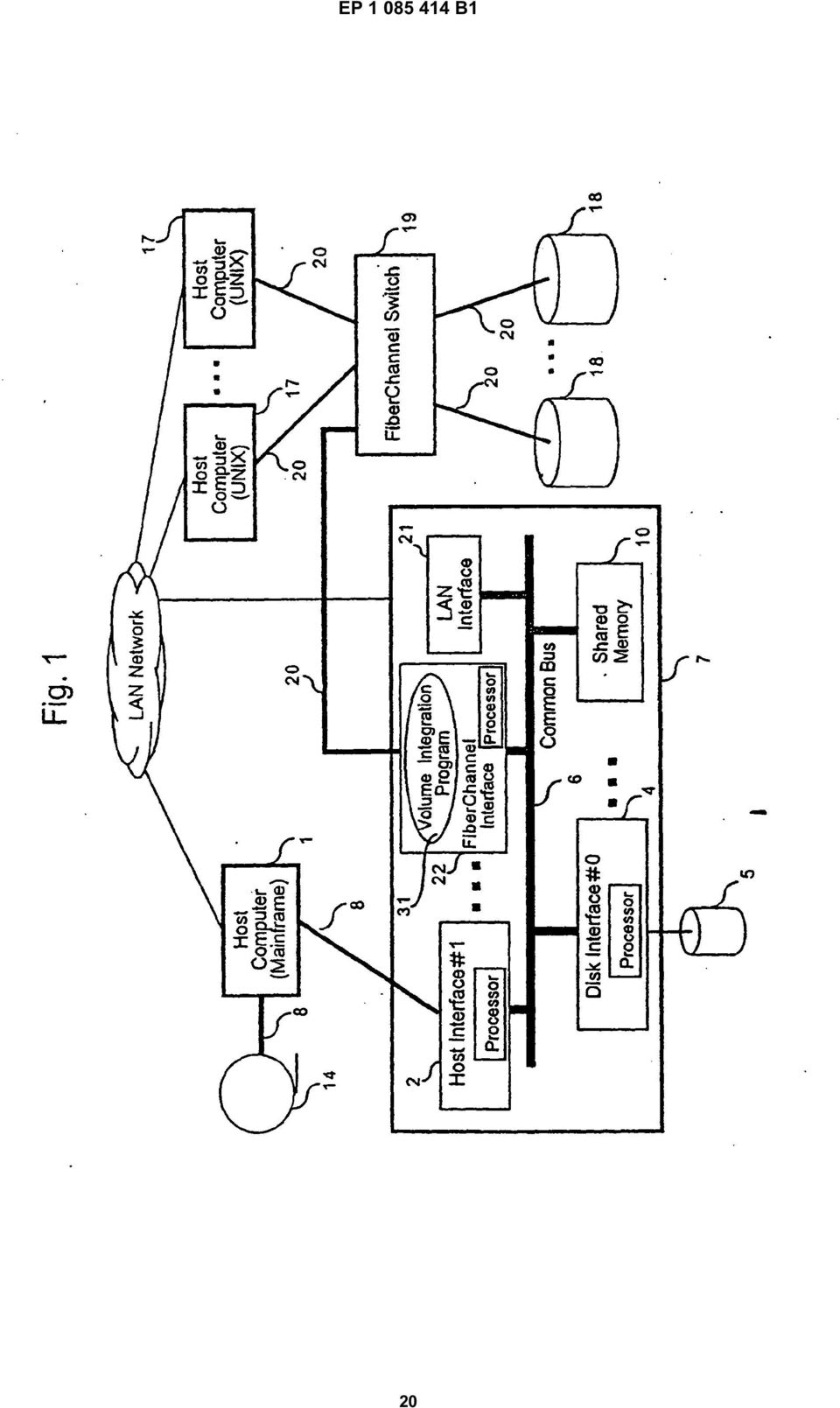
SAN Conceptual and Design Basics
 TECHNICAL NOTE VMware Infrastructure 3 SAN Conceptual and Design Basics VMware ESX Server can be used in conjunction with a SAN (storage area network), a specialized high speed network that connects computer
Storage Area Network
 Storage Area Network 2007 Infortrend Technology, Inc. All rights Reserved. Table of Contents Introduction...3 SAN Fabric...4 Advantages of SAN Solution...4 Fibre Channel SAN vs. IP SAN...4 Fibre Channel
VERITAS Backup Exec 9.0 for Windows Servers
 WHITE PAPER Data Protection Solutions for Network Attached Storage VERITAS Backup Exec 9.0 for Windows Servers VERSION INCLUDES TABLE OF CONTENTS STYLES 1 TABLE OF CONTENTS Background...3 Why Use a NAS
HiCommand Dynamic Link Manager (HDLM) for Windows Systems User s Guide
 for Windows Systems User s Guide") HiCommand Dynamic Link Manager (HDLM) for Windows Systems User s Guide MK-92DLM129-13 2007 Hitachi Data Systems Corporation, ALL RIGHTS RESERVED Notice: No part of this publication may be reproduced or
HiCommand Dynamic Link Manager (HDLM) for Windows Systems User s Guide MK-92DLM129-13 2007 Hitachi Data Systems Corporation, ALL RIGHTS RESERVED Notice: No part of this publication may be reproduced or
TEPZZ 65Z79 A_T EP 2 650 793 A1 (19) (11) EP 2 650 793 A1. (12) EUROPEAN PATENT APPLICATION published in accordance with Art.
 (11) EP 2 650 793 A1. (12) EUROPEAN PATENT APPLICATION published in accordance with Art.") (19) TEPZZ 65Z79 A_T (11) EP 2 650 793 A1 (12) EUROPEAN PATENT APPLICATION published in accordance with Art. 153(4) EPC (43) Date of publication: 16.10.2013 Bulletin 2013/42 (21) Application number: 12818771.3
(19) TEPZZ 65Z79 A_T (11) EP 2 650 793 A1 (12) EUROPEAN PATENT APPLICATION published in accordance with Art. 153(4) EPC (43) Date of publication: 16.10.2013 Bulletin 2013/42 (21) Application number: 12818771.3
M.Sc. IT Semester III VIRTUALIZATION QUESTION BANK 2014 2015 Unit 1 1. What is virtualization? Explain the five stage virtualization process. 2.
 M.Sc. IT Semester III VIRTUALIZATION QUESTION BANK 2014 2015 Unit 1 1. What is virtualization? Explain the five stage virtualization process. 2. What are the different types of virtualization? Explain
Network Attached Storage. Jinfeng Yang Oct/19/2015
 Network Attached Storage Jinfeng Yang Oct/19/2015 Outline Part A 1. What is the Network Attached Storage (NAS)? 2. What are the applications of NAS? 3. The benefits of NAS. 4. NAS s performance (Reliability
Building High-Performance iscsi SAN Configurations. An Alacritech and McDATA Technical Note
 Building High-Performance iscsi SAN Configurations An Alacritech and McDATA Technical Note Building High-Performance iscsi SAN Configurations An Alacritech and McDATA Technical Note Internet SCSI (iscsi)
TEPZZ 96 A_T EP 2 961 111 A1 (19) (11) EP 2 961 111 A1. (12) EUROPEAN PATENT APPLICATION published in accordance with Art.
 (11) EP 2 961 111 A1. (12) EUROPEAN PATENT APPLICATION published in accordance with Art.") (19) TEPZZ 96 A_T (11) EP 2 961 111 A1 (12) EUROPEAN PATENT APPLICATION published in accordance with Art. 13(4) EPC (43) Date of publication:.12.1 Bulletin 1/3 (21) Application number: 147426.7 (22) Date
(19) TEPZZ 96 A_T (11) EP 2 961 111 A1 (12) EUROPEAN PATENT APPLICATION published in accordance with Art. 13(4) EPC (43) Date of publication:.12.1 Bulletin 1/3 (21) Application number: 147426.7 (22) Date
Optimizing LTO Backup Performance
 Optimizing LTO Backup Performance July 19, 2011 Written by: Ash McCarty Contributors: Cedrick Burton Bob Dawson Vang Nguyen Richard Snook Table of Contents 1.0 Introduction... 3 2.0 Host System Configuration...
Rapidly Growing Linux OS: Features and Reliability
 Rapidly Growing Linux OS: Features and Reliability V Norio Kurobane (Manuscript received May 20, 2005) Linux has been making rapid strides through mailing lists of volunteers working in the Linux communities.
Logical Partitioning Feature of CB Series Xeon Servers Suitable for Robust and Reliable Cloud
 Hitachi Review Vol. 61 (2012), No. 2 65 Partitioning Feature of CB Series Xeon Servers Suitable for Robust and Reliable Cloud Hitoshi Ueno, Ph. D., PE.jp Shinichi Matsumura OVERVIEW: is Hitachi s own server
IBM ^ xseries ServeRAID Technology
 IBM ^ xseries ServeRAID Technology Reliability through RAID technology Executive Summary: t long ago, business-critical computing on industry-standard platforms was unheard of. Proprietary systems were
EUROPEAN PATENT SPECIFICATION. (51) IntCL: G06F 13/10< 200B 1 > G06F 13/42( 2 OO 601 > (56) References cited: WO-A-97/19402 US-A- 6 085 265
 IntCL: G06F 13/10< 200B 1 > G06F 13/42( 2 OO 601 > (56) References cited: WO-A-97/19402 US-A- 6 085 265") (19) J Europäisches Patentamt European Patent Office Office européen des brevets (H) EP 1246 071 B1 (12) EUROPEAN PATENT SPECIFICATION (45) Date of publication and mention of the grant of the patent: 10.05.2006
(19) J Europäisches Patentamt European Patent Office Office européen des brevets (H) EP 1246 071 B1 (12) EUROPEAN PATENT SPECIFICATION (45) Date of publication and mention of the grant of the patent: 10.05.2006
Hitachi Path Management & Load Balancing with Hitachi Dynamic Link Manager and Global Link Availability Manager
 Hitachi Data System s WebTech Series Hitachi Path Management & Load Balancing with Hitachi Dynamic Link Manager and Global Link Availability Manager The HDS WebTech Series Dynamic Load Balancing Who should
DAS to SAN Migration Using a Storage Concentrator
 DAS to SAN Migration Using a Storage Concentrator April 2006 All trademark names are the property of their respective companies. This publication contains opinions of StoneFly, Inc. which are subject to
Implementing Network Attached Storage. Ken Fallon Bill Bullers Impactdata
 Implementing Network Attached Storage Ken Fallon Bill Bullers Impactdata Abstract The Network Peripheral Adapter (NPA) is an intelligent controller and optimized file server that enables network-attached
Configuration Maximums VMware Infrastructure 3
 Technical Note Configuration s VMware Infrastructure 3 When you are selecting and configuring your virtual and physical equipment, you must stay at or below the maximums supported by VMware Infrastructure
Backup Exec 9.1 for Windows Servers. SAN Shared Storage Option
 WHITE PAPER Optimized Performance for SAN Environments Backup Exec 9.1 for Windows Servers SAN Shared Storage Option 11/20/2003 1 TABLE OF CONTENTS Executive Summary...3 Product Highlights...3 Approaches
Backup Exec 15. Quick Installation Guide
 Backup Exec 15 Quick Installation Guide 21344987 Documentation version: 15 PN: 21344987 Legal Notice Copyright 2015 Symantec Corporation. All rights reserved. Symantec, the Symantec Logo, the Checkmark
Implementing a Digital Video Archive Based on XenData Software
 Based on XenData Software The Video Edition of XenData Archive Series software manages a digital tape library on a Windows Server 2003 platform to create a digital video archive that is ideal for the demanding
FlexArray Virtualization
 Updated for 8.2.1 FlexArray Virtualization Installation Requirements and Reference Guide NetApp, Inc. 495 East Java Drive Sunnyvale, CA 94089 U.S. Telephone: +1 (408) 822-6000 Fax: +1 (408) 822-4501 Support
Computer Organization & Architecture Lecture #19
 Computer Organization & Architecture Lecture #19 Input/Output The computer system s I/O architecture is its interface to the outside world. This architecture is designed to provide a systematic means of
(51) Int Cl.: H04L 12/28 (2006.01) H04L 29/06 (2006.01) H04L 12/56 (2006.01)
 Int Cl.: H04L 12/28 (2006.01) H04L 29/06 (2006.01) H04L 12/56 (2006.01)") (19) (12) EUROPEAN PATENT SPECIFICATION (11) EP 1 096 7 B1 (4) Date of publication and mention of the grant of the patent: 11.03.09 Bulletin 09/11 (1) Int Cl.: H04L 12/28 (06.01) H04L 29/06 (06.01) H04L
(19) (12) EUROPEAN PATENT SPECIFICATION (11) EP 1 096 7 B1 (4) Date of publication and mention of the grant of the patent: 11.03.09 Bulletin 09/11 (1) Int Cl.: H04L 12/28 (06.01) H04L 29/06 (06.01) H04L
SAN and NAS Bandwidth Requirements
 SAN and NAS Bandwidth Requirements Exploring Networked Storage Scott Kipp Office of the CTO Brocade Inc. Categorizing Storage - DAS SAN - NAS Directly Attached Storage DAS Storage that is connected point-to-point
Using High Availability Technologies Lesson 12
 Using High Availability Technologies Lesson 12 Skills Matrix Technology Skill Objective Domain Objective # Using Virtualization Configure Windows Server Hyper-V and virtual machines 1.3 What Is High Availability?
HBA Virtualization Technologies for Windows OS Environments
 HBA Virtualization Technologies for Windows OS Environments FC HBA Virtualization Keeping Pace with Virtualized Data Centers Executive Summary Today, Microsoft offers Virtual Server 2005 R2, a software
Areas Covered. Chapter 1 Features (Overview/Note) Chapter 2 How to Use WebBIOS. Chapter 3 Installing Global Array Manager (GAM)
 Chapter 2 How to Use WebBIOS. Chapter 3 Installing Global Array Manager (GAM)") PRIMERGY RX300 S2 Onboard SCSI RAID User s Guide Areas Covered Chapter 1 Features (Overview/Note) This chapter explains the overview of the disk array and features of the SCSI array controller. Chapter
PRIMERGY RX300 S2 Onboard SCSI RAID User s Guide Areas Covered Chapter 1 Features (Overview/Note) This chapter explains the overview of the disk array and features of the SCSI array controller. Chapter
EMC Virtual Infrastructure for SAP Enabled by EMC Symmetrix with Auto-provisioning Groups, Symmetrix Management Console, and VMware vcenter Converter
 EMC Virtual Infrastructure for SAP Enabled by EMC Symmetrix with Auto-provisioning Groups, VMware vcenter Converter A Detailed Review EMC Information Infrastructure Solutions Abstract This white paper
VERITAS VERTEX Initiative
 VERITAS VERTEX Initiative Frequently Asked Questions Q1. What is the VERITAS VERTEX Initiative? A1. The VERITAS VERTEX Initiative is a set of NetBackup solutions from VERITAS that will deliver alternate
Terminal Server Software and Hardware Requirements. Terminal Server. Software and Hardware Requirements. Datacolor Match Pigment Datacolor Tools
 Terminal Server Software and Hardware Requirements Datacolor Match Pigment Datacolor Tools January 21, 2011 Page 1 of 8 Introduction This document will provide preliminary information about the both the
SEMI SYMMETRIC METHOD OF SAN STORAGE VIRTUALIZATION
 SEMI SYMMETRIC METHOD OF SAN STORAGE VIRTUALIZATION Mrs. Dhanamma Jagli¹, Mr. Ramesh Solanki1², Mrs. Rohini Temkar³, Mrs. Laxmi Veshapogu 4 1,2, 3 Assistant Professor, Department of MCA, V.E.S. Institute
Increase Database Performance by Implementing Cirrus Data Solutions DCS SAN Caching Appliance With the Seagate Nytro Flash Accelerator Card
 Implementing Cirrus Data Solutions DCS SAN Caching Appliance With the Seagate Nytro Technology Paper Authored by Rick Stehno, Principal Database Engineer, Seagate Introduction Supporting high transaction
Agenda. Enterprise Application Performance Factors. Current form of Enterprise Applications. Factors to Application Performance.
 Agenda Enterprise Performance Factors Overall Enterprise Performance Factors Best Practice for generic Enterprise Best Practice for 3-tiers Enterprise Hardware Load Balancer Basic Unix Tuning Performance
Fibre Channel Overview of the Technology. Early History and Fibre Channel Standards Development
 Fibre Channel Overview from the Internet Page 1 of 11 Fibre Channel Overview of the Technology Early History and Fibre Channel Standards Development Interoperability and Storage Storage Devices and Systems
Windows Server 2008 R2 Hyper-V Live Migration
 Windows Server 2008 R2 Hyper-V Live Migration Table of Contents Overview of Windows Server 2008 R2 Hyper-V Features... 3 Dynamic VM storage... 3 Enhanced Processor Support... 3 Enhanced Networking Support...
Data Storage Solutions
 Data Storage Solutions Module 1.2 2006 EMC Corporation. All rights reserved. Data Storage Solutions - 1 Data Storage Solutions Upon completion of this module, you will be able to: List the common storage
Upgrading Data Center Network Architecture to 10 Gigabit Ethernet
 Intel IT IT Best Practices Data Centers January 2011 Upgrading Data Center Network Architecture to 10 Gigabit Ethernet Executive Overview Upgrading our network architecture will optimize our data center
Violin Memory Arrays With IBM System Storage SAN Volume Control
 Technical White Paper Report Best Practices Guide: Violin Memory Arrays With IBM System Storage SAN Volume Control Implementation Best Practices and Performance Considerations Version 1.0 Abstract This
Hewlett Packard - NBU partnership : SAN (Storage Area Network) или какво стои зад облаците
 или какво стои зад облаците") Hewlett Packard - NBU partnership : SAN (Storage Area Network) или какво стои зад облаците Why SAN? Business demands have created the following challenges for storage solutions: Highly available and easily
Hewlett Packard - NBU partnership : SAN (Storage Area Network) или какво стои зад облаците Why SAN? Business demands have created the following challenges for storage solutions: Highly available and easily
Remote Copy Technology of ETERNUS6000 and ETERNUS3000 Disk Arrays
 Remote Copy Technology of ETERNUS6000 and ETERNUS3000 Disk Arrays V Tsutomu Akasaka (Manuscript received July 5, 2005) This paper gives an overview of a storage-system remote copy function and the implementation
Oracle Database Deployments with EMC CLARiiON AX4 Storage Systems
 Oracle Database Deployments with EMC CLARiiON AX4 Storage Systems Applied Technology Abstract This white paper investigates configuration and replication choices for Oracle Database deployment with EMC
(51) Int Cl.: H04L 12/58 (2006.01) H04L 29/06 (2006.01)
 Int Cl.: H04L 12/58 (2006.01) H04L 29/06 (2006.01)") (19) TEPZZ_986 8 B_T (11) EP 1 986 382 B1 (12) EUROPEAN PATENT SPECIFICATION (4) Date of publication and mention of the grant of the patent: 19.02.14 Bulletin 14/08 (1) Int Cl.: H04L 12/8 (06.01) H04L
(19) TEPZZ_986 8 B_T (11) EP 1 986 382 B1 (12) EUROPEAN PATENT SPECIFICATION (4) Date of publication and mention of the grant of the patent: 19.02.14 Bulletin 14/08 (1) Int Cl.: H04L 12/8 (06.01) H04L
intelligent Bridging Architecture TM White Paper Increasing the Backup Window using the ATTO FibreBridge for LAN-free and Serverless Backups
 intelligent Bridging Architecture TM White Paper Increasing the Backup Window using the ATTO FibreBridge for LAN-free and Serverless Backups White Paper intelligent Bridging Architecture TM Increasing
Implementing Offline Digital Video Storage using XenData Software
 using XenData Software XenData software manages data tape drives, optionally combined with a tape library, on a Windows Server 2003 platform to create an attractive offline storage solution for professional
Provisioning Technology for Automation
 Provisioning Technology for Automation V Mamoru Yokoyama V Hiroshi Yazawa (Manuscript received January 17, 2007) Vendors have recently been offering more products and solutions for IT system automation
Disk-to-Disk Backup & Restore Application Note
 Disk-to-Disk Backup & Restore Application Note All trademark names are the property of their respective companies. This publication contains opinions of StoneFly, Inc., which are subject to change from
Data Replication User s Manual (Function Guide)
") NEC Storage Software Data Replication User s Manual (Function Guide) IS015-23E NEC Corporation 2003-2010 No part of the contents of this book may be reproduced or transmitted in any form without permission
NEC Storage Software Data Replication User s Manual (Function Guide) IS015-23E NEC Corporation 2003-2010 No part of the contents of this book may be reproduced or transmitted in any form without permission
Implementing an Automated Digital Video Archive Based on the Video Edition of XenData Software
 Implementing an Automated Digital Video Archive Based on the Video Edition of XenData Software The Video Edition of XenData Archive Series software manages one or more automated data tape libraries on
TECHNOLOGY BRIEF. Compaq RAID on a Chip Technology EXECUTIVE SUMMARY CONTENTS
 TECHNOLOGY BRIEF August 1999 Compaq Computer Corporation Prepared by ISSD Technology Communications CONTENTS Executive Summary 1 Introduction 3 Subsystem Technology 3 Processor 3 SCSI Chip4 PCI Bridge
(51) Int Cl.: G06F 11/14 (2006.01) G06F 17/30 (2006.01)
 Int Cl.: G06F 11/14 (2006.01) G06F 17/30 (2006.01)") (19) (11) EP 1 618 04 B1 (12) EUROPEAN PATENT SPECIFICATION (4) Date of publication and mention of the grant of the patent: 24.06.09 Bulletin 09/26 (21) Application number: 04779479.7 (22) Date of filing:
(19) (11) EP 1 618 04 B1 (12) EUROPEAN PATENT SPECIFICATION (4) Date of publication and mention of the grant of the patent: 24.06.09 Bulletin 09/26 (21) Application number: 04779479.7 (22) Date of filing:
Application-Oriented Storage Resource Management
 Application-Oriented Storage Resource Management V Sawao Iwatani (Manuscript received November 28, 2003) Storage Area Networks (SANs) have spread rapidly, and they help customers make use of large-capacity
An On-line Backup Function for a Clustered NAS System (X-NAS)
") _ An On-line Backup Function for a Clustered NAS System (X-NAS) Yoshiko Yasuda, Shinichi Kawamoto, Atsushi Ebata, Jun Okitsu, and Tatsuo Higuchi Hitachi, Ltd., Central Research Laboratory 1-28 Higashi-koigakubo,
_ An On-line Backup Function for a Clustered NAS System (X-NAS) Yoshiko Yasuda, Shinichi Kawamoto, Atsushi Ebata, Jun Okitsu, and Tatsuo Higuchi Hitachi, Ltd., Central Research Laboratory 1-28 Higashi-koigakubo,
Virtualizing the SAN with Software Defined Storage Networks
 Software Defined Storage Networks Virtualizing the SAN with Software Defined Storage Networks Introduction Data Center architects continue to face many challenges as they respond to increasing demands
Q & A From Hitachi Data Systems WebTech Presentation:
 Q & A From Hitachi Data Systems WebTech Presentation: RAID Concepts 1. Is the chunk size the same for all Hitachi Data Systems storage systems, i.e., Adaptable Modular Systems, Network Storage Controller,
Virtualization, Business Continuation Plan & Disaster Recovery for EMS -By Ramanj Pamidi San Diego Gas & Electric
 Virtualization, Business Continuation Plan & Disaster Recovery for EMS -By Ramanj Pamidi San Diego Gas & Electric 2001 San Diego Gas and Electric. All copyright and trademark rights reserved. Importance
Windows Server 2008 R2 Hyper-V Live Migration
 Windows Server 2008 R2 Hyper-V Live Migration White Paper Published: August 09 This is a preliminary document and may be changed substantially prior to final commercial release of the software described
This chapter explains how to update device drivers and apply hotfix.
 MegaRAID SAS User's Guide Areas Covered Before Reading This Manual This section explains the notes for your safety and conventions used in this manual. Chapter 1 Overview This chapter explains an overview
IOmark- VDI. Nimbus Data Gemini Test Report: VDI- 130906- a Test Report Date: 6, September 2013. www.iomark.org
 IOmark- VDI Nimbus Data Gemini Test Report: VDI- 130906- a Test Copyright 2010-2013 Evaluator Group, Inc. All rights reserved. IOmark- VDI, IOmark- VDI, VDI- IOmark, and IOmark are trademarks of Evaluator
Enabling Technologies for Distributed Computing
 Enabling Technologies for Distributed Computing Dr. Sanjay P. Ahuja, Ph.D. Fidelity National Financial Distinguished Professor of CIS School of Computing, UNF Multi-core CPUs and Multithreading Technologies
Virtualizing Microsoft SQL Server 2008 on the Hitachi Adaptable Modular Storage 2000 Family Using Microsoft Hyper-V
 Virtualizing Microsoft SQL Server 2008 on the Hitachi Adaptable Modular Storage 2000 Family Using Microsoft Hyper-V Implementation Guide By Eduardo Freitas and Ryan Sokolowski February 2010 Summary Deploying
Enabling Technologies for Distributed and Cloud Computing
 Enabling Technologies for Distributed and Cloud Computing Dr. Sanjay P. Ahuja, Ph.D. 2010-14 FIS Distinguished Professor of Computer Science School of Computing, UNF Multi-core CPUs and Multithreading
Performance Characteristics of VMFS and RDM VMware ESX Server 3.0.1
 Performance Study Performance Characteristics of and RDM VMware ESX Server 3.0.1 VMware ESX Server offers three choices for managing disk access in a virtual machine VMware Virtual Machine File System
Implementing a Digital Video Archive Using XenData Software and a Spectra Logic Archive
 Using XenData Software and a Spectra Logic Archive With the Video Edition of XenData Archive Series software on a Windows server and a Spectra Logic T-Series digital archive, broadcast organizations have
BrightStor ARCserve Backup for Windows
 BrightStor ARCserve Backup for Windows Tape RAID Option Guide r11.5 D01183-1E This documentation and related computer software program (hereinafter referred to as the "Documentation") is for the end user's
STORAGE. 2015 Arka Service s.r.l.
 STORAGE STORAGE MEDIA independently from the repository model used, data must be saved on a support (data storage media). Arka Service uses the most common methods used as market standard such as: MAGNETIC
Storage Area Network Configurations for RA8000/ESA12000 on Windows NT Intel
 Storage Area Network Configurations for RA8000/ESA12000 on Application Note AA-RHH6B-TE Visit Our Web Site for the Latest Information At Compaq we are continually making additions to our storage solutions
SAN TECHNICAL - DETAILS/ SPECIFICATIONS
 SAN TECHNICAL - DETAILS/ SPECIFICATIONS Technical Details / Specifications for 25 -TB Usable capacity SAN Solution Item 1) SAN STORAGE HARDWARE : One No. S.N. Features Description Technical Compliance
(51) Int Cl.: H04L 29/06 (2006.01) H04L 12/24 (2006.01)
 Int Cl.: H04L 29/06 (2006.01) H04L 12/24 (2006.01)") (19) (12) EUROPEAN PATENT SPECIFICATION (11) EP 1 231 74 B1 (4) Date of publication and mention of the grant of the patent: 16.03.11 Bulletin 11/11 (1) Int Cl.: H04L 29/06 (06.01) H04L 12/24 (06.01) (21)
(19) (12) EUROPEAN PATENT SPECIFICATION (11) EP 1 231 74 B1 (4) Date of publication and mention of the grant of the patent: 16.03.11 Bulletin 11/11 (1) Int Cl.: H04L 29/06 (06.01) H04L 12/24 (06.01) (21)
WHITEPAPER: Understanding Pillar Axiom Data Protection Options
 WHITEPAPER: Understanding Pillar Axiom Data Protection Options Introduction This document gives an overview of the Pillar Data System Axiom RAID protection schemas. It does not delve into corner cases
Introduction to MPIO, MCS, Trunking, and LACP
 Introduction to MPIO, MCS, Trunking, and LACP Sam Lee Version 1.0 (JAN, 2010) - 1 - QSAN Technology, Inc. http://www.qsantechnology.com White Paper# QWP201002-P210C lntroduction Many users confuse the
Open-E Data Storage Software and Intel Modular Server a certified virtualization solution
 Open-E Data Storage Software and Intel Modular Server a certified virtualization solution Contents 1. New challenges for SME IT environments 2. Open-E DSS V6 and Intel Modular Server: the ideal virtualization
XenData Video Edition. Product Brief:
 XenData Video Edition Product Brief: The Video Edition of XenData Archive Series software manages one or more automated data tape libraries on a single Windows 2003 server to create a cost effective digital
Terms of Reference Microsoft Exchange and Domain Controller/ AD implementation
 Terms of Reference Microsoft Exchange and Domain Controller/ AD implementation Overview Maldivian Red Crescent will implement it s first Microsoft Exchange server and replace it s current Domain Controller
BrightStor ARCserve Backup for Windows
 BrightStor ARCserve Backup for Windows Serverless Backup Option Guide r11.5 D01182-2E This documentation and related computer software program (hereinafter referred to as the "Documentation") is for the
IBM Tivoli Composite Application Manager for Microsoft Applications: Microsoft Hyper-V Server Agent Version 6.3.1 Fix Pack 2.
 IBM Tivoli Composite Application Manager for Microsoft Applications: Microsoft Hyper-V Server Agent Version 6.3.1 Fix Pack 2 Reference IBM Tivoli Composite Application Manager for Microsoft Applications:
Lab Validation Report. By Steven Burns. Month Year
 1 Hyper-V v2 Host Level Backups Using Symantec NetBackup 7.0 and the Hitachi VSS Hardware Provider with the Hitachi Adaptable Modular Storage 2000 Family Lab Validation Report By Steven Burns March 2011
Technologies of ETERNUS Virtual Disk Library
 Technologies of ETERNUS Virtual Disk Library V Shigeo Konno V Tadashi Kumasawa (Manuscript received September 26, 2005) In today s dramatically changing business environment, the extensive broadband environment
Data Storage at IBT. Topics. Storage, Concepts and Guidelines
 Data Storage at IBT Storage, Concepts and Guidelines Topics Hard Disk Drives (HDDs) Storage Technology New Storage Hardware at IBT Concepts and Guidelines? 2 1 Hard Disk Drives (HDDs) First hard disk:
TEPZZ 9 Z5A_T EP 2 922 305 A1 (19) (11) EP 2 922 305 A1. (12) EUROPEAN PATENT APPLICATION published in accordance with Art.
 (11) EP 2 922 305 A1. (12) EUROPEAN PATENT APPLICATION published in accordance with Art.") (19) TEPZZ 9 ZA_T (11) EP 2 922 A1 (12) EUROPEAN PATENT APPLICATION published in accordance with Art. 13(4) EPC (43) Date of publication: 23.09.1 Bulletin 1/39 (21) Application number: 1386446.2 (22) Date
(19) TEPZZ 9 ZA_T (11) EP 2 922 A1 (12) EUROPEAN PATENT APPLICATION published in accordance with Art. 13(4) EPC (43) Date of publication: 23.09.1 Bulletin 1/39 (21) Application number: 1386446.2 (22) Date
Customer Education Services Course Overview
 Customer Education Services Course Overview Accelerated SAN Essentials (UC434S) This five-day course provides a comprehensive and accelerated understanding of SAN technologies and concepts. Students will
ISRX207VE11-1. NEC Storage PathManager for VMware Installation Guide
 NEC Storage PathManager for VMware Installation Guide Preface This document describes about the installation of the program products in the CD labeled as: NEC Storage PathManager for VMware English Version
Integrated Virtualization Manager ESCALA REFERENCE 86 A1 82FA 01
 Integrated Virtualization Manager ESCALA REFERENCE 86 A1 82FA 01 ESCALA Integrated Virtualization Manager Hardware May 2009 BULL CEDOC 357 AVENUE PATTON B.P.20845 49008 ANGERS CEDEX 01 FRANCE REFERENCE
Data Storage Technologies
 STUDY GUIDE Data Storage Technologies Ramūnas MARKAUSKAS Vilnius University 2012 Data Storage Technologies Study Guide Cycle: 1 st level Study program: Information Technologies Course unit code: ITDST
Hitachi Essential NAS Platform, NAS Gateway with High Cost Performance
 , NAS Gateway with High Cost Performance 80, NAS Gateway with High Cost Performance Katsumi Hirezaki Seiichi Higaki Hiroki Kanai Toru Kawasaki OVERVIEW: Over recent years, within the changing business
Best Practices for Installing and Configuring the Hyper-V Role on the LSI CTS2600 Storage System for Windows 2008
 Best Practices Best Practices for Installing and Configuring the Hyper-V Role on the LSI CTS2600 Storage System for Windows 2008 Installation and Configuration Guide 2010 LSI Corporation August 13, 2010
Microsoft Exchange Solutions on VMware
 Design and Sizing Examples: Microsoft Exchange Solutions on VMware Page 1 of 19 Contents 1. Introduction... 3 1.1. Overview... 3 1.2. Benefits of Running Exchange Server 2007 on VMware Infrastructure 3...
Configuring RAID for Optimal Performance
 Configuring RAID for Optimal Performance Intel RAID Controller SRCSASJV Intel RAID Controller SRCSASRB Intel RAID Controller SRCSASBB8I Intel RAID Controller SRCSASLS4I Intel RAID Controller SRCSATAWB
Date: March 2006. Reference No. RTS-CB 018
 Customer Bulletin Product Model Name: CS3102 and FS3102 subsystems Date: March 2006 Reference No. RTS-CB 018 SUBJECT: Volumes greater than 2TB on Windows OS Overview This document explores how different
Hitachi s Midrange Disk Array as Platform for DLCM Solution
 Hitachi Review Vol. 54 (2005), No. 2 87 Hitachi s Midrange Disk Array as Platform for DLCM Solution Teiko Kezuka Ikuya Yagisawa Azuma Kano Seiki Morita OVERVIEW: With the Internet now firmly established
NEC Storage Manager Data Replication User's Manual (Function Guide)
") NEC Storage Manager Data Replication User's Manual (Function Guide) NEC Corporation 2001-2003 No part of the contents of this book may be reproduced or transmitted in any form without permission of NEC
NEC Storage Manager Data Replication User's Manual (Function Guide) NEC Corporation 2001-2003 No part of the contents of this book may be reproduced or transmitted in any form without permission of NEC
SCSI support on Xen. MATSUMOTO Hitoshi matsumotohitosh@jp.fujitsu.com Fujitsu Ltd.
 SCSI support on Xen MATSUMOTO Hitoshi matsumotohitosh@jp.fujitsu.com Fujitsu Ltd. Why SCSI? Current Xen status personal use available business use reliability and availability are required reliability
COMPARING STORAGE AREA NETWORKS AND NETWORK ATTACHED STORAGE
 COMPARING STORAGE AREA NETWORKS AND NETWORK ATTACHED STORAGE Complementary technologies provide unique advantages over traditional storage architectures Often seen as competing technologies, Storage Area
Maximizing Backup and Restore Performance of Large Databases
 Maximizing Backup and Restore Performance of Large Databases - 1 - Forward (from Meta Group) Most companies critical data is being stored within relational databases. Over 90% of all mission critical systems,
EP 2 455 926 A1 (19) (11) EP 2 455 926 A1 (12) EUROPEAN PATENT APPLICATION. (43) Date of publication: 23.05.2012 Bulletin 2012/21
 (11) EP 2 455 926 A1 (12) EUROPEAN PATENT APPLICATION. (43) Date of publication: 23.05.2012 Bulletin 2012/21") (19) (12) EUROPEAN PATENT APPLICATION (11) EP 2 4 926 A1 (43) Date of publication: 23.0.2012 Bulletin 2012/21 (21) Application number: 11190024.7 (1) Int Cl.: G08B 2/14 (2006.01) G08B 2/00 (2006.01) G0B
(19) (12) EUROPEAN PATENT APPLICATION (11) EP 2 4 926 A1 (43) Date of publication: 23.0.2012 Bulletin 2012/21 (21) Application number: 11190024.7 (1) Int Cl.: G08B 2/14 (2006.01) G08B 2/00 (2006.01) G0B
UN 4013 V - Virtual Tape Libraries solutions update...
 UN 4013 V - Virtual Tape Libraries solutions update... - a Unisys storage partner Key issues when considering virtual tape Connectivity is my platform supported by whom? (for Unisys environments, MCP,
Best Practices for Implementing Autodesk Vault
 AUTODESK VAULT WHITE PAPER Best Practices for Implementing Autodesk Vault Introduction This document guides you through the best practices for implementing Autodesk Vault software. This document covers
TEPZZ 68575_A_T EP 2 685 751 A1 (19) (11) EP 2 685 751 A1. (12) EUROPEAN PATENT APPLICATION published in accordance with Art.
 (11) EP 2 685 751 A1. (12) EUROPEAN PATENT APPLICATION published in accordance with Art.") (19) TEPZZ 687_A_T (11) EP 2 68 71 A1 (12) EUROPEAN PATENT APPLICATION published in accordance with Art. 3(4) EPC (43) Date of publication:.01.14 Bulletin 14/03 (21) Application number: 1278849.6 (22)
(19) TEPZZ 687_A_T (11) EP 2 68 71 A1 (12) EUROPEAN PATENT APPLICATION published in accordance with Art. 3(4) EPC (43) Date of publication:.01.14 Bulletin 14/03 (21) Application number: 1278849.6 (22)
Intel Rapid Storage Technology
 Intel Rapid Storage Technology User Guide August 2011 Revision 1.0 1 Document Number: XXXXXX INFORMATION IN THIS DOCUMENT IS PROVIDED IN CONNECTION WITH INTEL PRODUCTS. NO LICENSE, EXPRESS OR IMPLIED,
Doubling the I/O Performance of VMware vsphere 4.1
 White Paper Doubling the I/O Performance of VMware vsphere 4.1 with Broadcom 10GbE iscsi HBA Technology This document describes the doubling of the I/O performance of vsphere 4.1 by using Broadcom 10GbE