Pneumatic Air Conditioning Pressurization
|
|
|
- Juniper Wells
- 10 years ago
- Views:
Transcription
1 EMBRAER 135/145 Pneumatic Air Conditioning Pressurization

2 GENERAL The pneumatic system can be supplied by the engines, APU or a ground pneumatic source. The APU or ground pneumatic source supplies the system prior to the engine start. The engines normally supply bleed air for pneumatics after engine start. The air conditioning system receives air from the pneumatic system and provides conditioned air to the cabin. The system is controlled by two Environmental Control Units (ECU). The pressurization system uses bleed air from the air conditioning system to pressurize the airplane. Cabin pressure is controlled by modulating the outflow valves. The system is controlled by an automatic mode and has a manual back-up mode. Cooling for rear and forward electronic compartments is provided by the ventilation system. System information and messages are presented on the EICAS. Page 1

3 PNEUMATIC SYSTEM The pneumatic system receives compressed and hot air from the following sources: Engines compression stage APU Ground pneumatic source The pneumatic system is used for: engine start, air conditioning, pressurization and anti-ice system. Engine bleed air comes from the 9 th (low pressure) or 14 th (high pressure) engine stages depending on the system demand. The 14 th stage High Stage Valve (HSV), which is electrically commanded and pneumatically-actuated, opens automatically during low engine thrust operations, engine cross bleed start and anti-ice operation. As thrust increases, the HSV closes and the 9 th BACV (Bleed Air Check Valve) opens supplying bleed air to the system. Bleed air for engine anti-ice system is provided through the tapping upstream of the HSV. An Engine Bleed Valve (EBV), which is electrically commanded through the Bleed Air Button and pneumatically-actuated, is installed downstream of the pre-cooler. Bleed air for the Air Turbine Starter (refer to Section Powerplant) is provided through the tapping downstream of the EBV. Each engine supplies air to its corresponding air conditioning pack and anti-ice system when the respective EBV is open. During take-off in specific thrust modes using engine bleed air, the operative air conditioning pack is closed by FADEC's ECS-OFF logic signal, featuring no engine bleed airflow demand when operating under no icing condition. With no engine bleed air demand and high engine's thrust set, for airplanes Post-Mod. SB or equipped with an equivalent modification factory incorporated, EBV regulates its downstream pressure in the vicinities of its closed position and then BLD 1-2 VLV CLSD EICAS advisory message may be displayed for airplanes equipped with EICAS version 19 and on. Page 2
 opens supplying bleed air to the system.")
4 In case of icing encounter during no bleed airflow demand, for airplanes Pre-Mod SB EBV remains open and for airplanes Post-Mod SB or equipped with an equivalent modification factory incorporated, EBV is opened by the pneumatic system's functional logic to allow engine bleed airflow to anti-ice system. A Cross-Bleed Valve (CBV), which is electrically commanded through the Cross Bleed Knob and pneumatically actuated, provides the segregation or interconnection between both sides in case of APU operation or one engine pneumatic supply. The pneumatic system s functional logic opens or closes automatically the CBV, if the Cross Bleed Knob is on AUTO position, during engine start, depending on the available pneumatic source: APU, ground pneumatic source or opposite engine. Page 3

5 PNEUMATIC SYSTEM SCHEMATIC Page 4

6 The functional logic opens automatically the CBV and both HSVs and closes the left air conditioning pack below ft, whenever the antiicing system is operating, on airplanes Pre-Mod. SB On airplanes equipped with a pressure regulating and shutoff EBVs (Post-Mod. SB ), the functional logic also opens both HSVs and closes one pack below ft, but does not open the CBV if the anti-icing system is operating. Airplanes Pre-Mod. SB Air Conditioning On Cross-bleed Closed Ice Protection On Cross-bleed Open Airplanes Post-Mod. SB or equipped with an equivalent modification factory incorporated. Cross-bleed Closed Bleed air from the APU, that is used primarily as an auxiliary pneumatic source, is provided in the left side of the pneumatic system to supply the air conditioning and engine starting either on ground or inflight. An APU Bleed Valve (ABV), which is electrically controlled through the APU Bleed Button and pneumatically-actuated, provides APU bleed control. The pneumatic system functional logic automatically closes the ABV whenever any engine is supplying bleed air to the left pneumatic side. An APU Check Valve is installed downstream of the APU bleed valve. A ground pneumatic source connection, including a check valve, is installed on the right side of the pneumatic system. Its main purpose is to supply pressurized air to start the engines. Leak detectors (thermal switches) are installed along all the pneumatic lines. Should a duct leakage occur, these detectors activate a warning message in the EICAS. Should an intense hot air leakage occur three Massive Leakage Detectors (thermal switches formerly located at the pre-cooler and currently located in the rear electronic compartment area) will close the EBV of the affected side, as well as the CBV. Bleed temperatures upstream and downstream of the pre-cooler are monitored through temperature sensors. Temperature downstream of the pre-cooler is presented on a vertical bar indication on the MFD. Page 5

7 INTEGRATED PNEUMATIC SYSTEM SCHEMATIC Page 6

8 PNEUMATIC SYSTEM FUNCTIONAL LOGIC The pneumatic system functional logic provides automatic control and protection for itself and the user systems, giving priority according to the airplane operation or condition. ENGINE BLEED VALVE LOGIC The Engine Bleed Valve (EBV) opens when the following conditions occur simultaneously: Bleed Air Button is pressed to open the valve; Respective Essential Bus is energized; There is no massive leakage on the respective side of the rear electronic compartment; There is no leakage downstream of the respective pre-cooler; Respective engine N2 is above 56.4%; and Respective engine fire extinguishing handle is not pulled. Bleed is requested by one of the bleed consuming systems (airplanes Post-Mod. SB ). APU BLEED VALVE OPERATIONAL LOGIC The APU Bleed Valve (ABV) receives an electrical input to open when the following conditions occur simultaneously: APU Bleed Button is pressed to open the valve; Essential DC Bus 1 is energized; Engine 1 bleed valve is closed (no pressure from the left side); Engine 2 bleed valve or cross-bleed valve is closed (no pressure from the right side); APU rpm above 95% after 7 seconds; and There is no massive leakage on the APU line. Page 7

9 CROSS BLEED VALVE OPERATIONAL LOGIC The Cross-Bleed Valve (CBV) receives an electrical input to open when the following conditions occur: Essential DC Bus 2 is energized; There is no massive bleed leakage downstream of the pre-cooler or in the Rear Electronic Compartment; and Cross Bleed Knob is set to OPEN; or Cross Bleed Knob is set to AUTO and one of the following conditions occurs: Engine 2 is starting; or Engine 1 is starting assisted by engine 2 or external pneumatic source (with APU Bleed Valve manually commanded to the close position); or The Horizontal Stabilizer Anti-Icing System is operating (airplanes Pre-Mod. SB ). Page 8
; or The Horizontal Stabilizer Anti-Icing System is operating (airplanes Pre-Mod.")
10 EICAS MESSAGES TYPE MESSAGE MEANING BLD 1 (2) LEAK Duct leakage in the BLD APU LEAK associated bleed line. Temperature in the duct region exceeds 91 C (195 F). WARNING The switch deactivates at 79 C (175 F). BLD 1 (2) OVTEMP Associated pre-cooler downstream temperature above 305 C (581 F). APU BLD VLV FAIL Disagreement between actual position and commanded position of the APU Bleed Valve. BLD 1 (2) LOW TEMP Abnormal low or asymmetric bleed temperature, or precooler outlet temperature sensor failure. BLD 1 (2) VLV FAIL Disagreement between actual position and commanded position of the associated CAUTION Engine Bleed Valve. CROSS BLD FAIL Disagreement between actual position and commanded position of the Cross-Bleed Valve. CROSS BLD SW OFF Cross Bleed Knob selected CLOSED with at least one engine running after brake release. HS VLV 1 (2) FAIL Disagreement between actual position and commanded position of the associated High Stage Valve. BLD 1 (2) VLV CLSD Associated Engine Bleed Valve position. This message is inhibited on ground or ADVISORY during associated engine start. CROSS BLD OPEN Cross Bleed Valve open. Page 9
 LOW TEMP Abnormal low or asymmetric bleed temperature, or precooler outlet temperature sensor failure.")
11 AIR CONDITIONING SYSTEM Airplane air conditioning is provided by two the Environmental Control Units (ECU) supplied by the Pneumatic System. Each side is provided with independent controls, protection devices, and cross-connected air distribution lines for the various modes of operation. Cockpit and passenger cabin temperature selections are independent and may be controlled either manually or automatically. The left ECU controls the temperature in the cockpit and the right ECU controls the temperature passenger cabin. The system is normally operated in the automatic mode. In case of automatic mode failure, a manual mode is available. The pilots may transfer the passenger cabin temperature control to the Attendant Panel. The air conditioning distribution is performed by the gasper system and general outlets with cross-connection between the cockpit and passenger cabin lines. This feature, associated with the ram air inlets, allows the cockpit and passenger cabin to be supplied with fresh air, in case of failure of both ECUs. Recirculating air, driven by two electrical fans, is mixed to fresh air in order to improve passenger and crewmembers' comfort. A ground cart connection is available at the right-hand duct, connected to the outside through a check valve in the fuselage. The preconditioned air from the ground cart is delivered to the cabin directly through the distribution lines. The air conditioning system incorporates protection features in the temperature controllers which shut off the system in case of malfunctions (duct leakage, duct overtemperature, and pack overtemperature). The cockpit and passenger cabin temperature indications are presented on the MFD. Caution and advisory messages are presented on the EICAS. Page 10

12 ECU OPERATION Each ECU consists of a dual heat exchanger, an air cycle machine (compressor, turbine, and fan), a condenser, a water separator and related control and protective devices, installed forward of the airplane wing root, inside the wing-to-fuselage fairing. The automatically-controlled bleed air from the pneumatic system supplies the ECU. Downstream pressure is regulated by the Pack Valve (Pressure Regulating and Shutoff Valve). After the Pack Valve, the airflow is divided into two lines: - One cold line that passes through to the Air Cycle Machine. - One hot line that bypasses the Air Cycle Machine. Both airflow lines are gathered at the expansion turbine discharge. In the Air Cycle Machine (ACM), air is cooled in the primary heat exchanger and passes through the compressor, thus causing a pressure increase. The air then goes to the secondary heat exchanger where it is cooled again. After leaving the secondary heat exchanger, the high-pressure cooled air passes through a condenser and a water separator for condensed water removal. Spray nozzles uses the separated water to improve the heat exchanger efficiency. The main airstream is ducted to the turbine and expanded to provide power for the compressor and cooling fan. This energy removal produces very low turbine discharge temperatures, achieving adequate low temperatures in the process. The cold exit air is mixed with warm air supplied by the recirculation fan and/or with the hot bypass air immediately upon leaving the turbine. A check valve is provided in the recirculation duct to prevent reverse flow if the recirculation fan is inoperative. The ECU outlet air temperature is controlled through the dual temperature control valve. One valve adds hot bleed air to the turbine discharge while the other valve restricts the compressor inlet flow. The ECUs are cooled in flight by external the ACM fans, using the external ram air. On the ground, the ECUs are cooled by the ACM fans only. The system has emergency ventilation, as an alternate means to allow the outside air into the cabin. The impact air passes through the same ram air inlets that are used to cool the dual heat exchangers. Page 11

13 AIR CONDITIONING SYSTEM SCHEMATIC Page 12
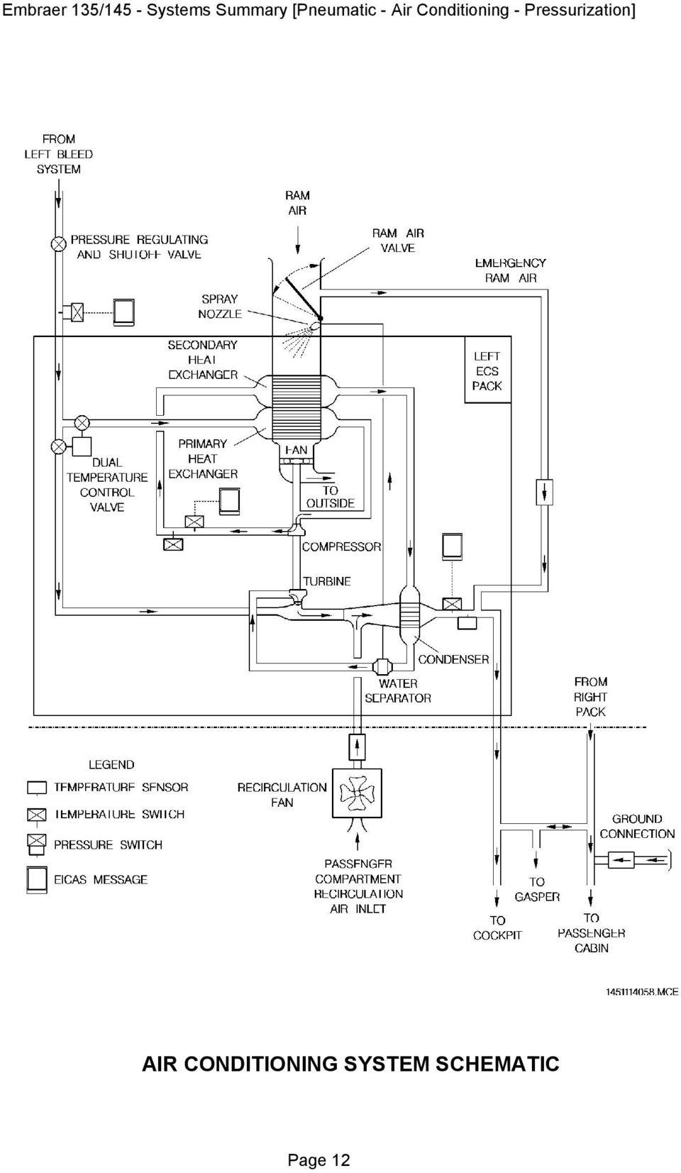
14 When the ECUs air supply is shut off in flight, the emergency ram air is activated and the ram air valves are opened automatically, allowing ram air to be routed to the distribution lines. Ram air may also be used to ventilate the airplane interior for cabin smoke evacuation and cabin ventilation purposes with the airplane depressurized and the ECUs turned off. NOTE: The Pneumatic System automatic logic closes the left Pack Valve whenever the anti-icing system is operating below ft. CABIN TEMPERATURE CONTROL AUTO MODE In the automatic mode (temperature knobs pressed), the temperatures in the passenger cabin and in the cockpit are controlled by the digital temperature controllers that receive information from the temperature sensors (ducts, passenger cabin, or cockpit), maintaining the temperature set on the associated temperature knob. MANUAL MODE In manual mode (temperature knobs pulled), the temperature in the passenger cabin and in the cockpit are controlled by the temperature control module, that receives information from the temperature knobs and the duct temperature sensor. The manual mode should be used only if a failure occurs in the automatic mode and may be noticed when the temperature is not maintained within the temperature limits of the automatic mode (between 18 and 29 C) after cabin temperature stabilization. If switching from auto mode to manual mode is required, proceed as follows: Set the knob to mid range position (12 o clock). Wait for system to stabilize (approximately 30 seconds). Switch to manual. Smoothly turn the knob to the required point. Once in the manual mode, the pilot must continuously monitor the temperature and actuate on the Temperature and Mode Selector Knob. NOTE: On airplanes Pre-Mod. SB , for cruise flight times of 1:30 h or longer, it is recommended that the passenger cabin temperature be controlled by using the manual mode. Page 13
, the temperatures in the passenger cabin and in the cockpit are controlled by the digital temperature controllers")
15 AIR CONDITIONING DISTRIBUTION The air conditioning distribution system provides conditioned air to the cockpit and passenger cabin. The main source of conditioned air to the cockpit is the left pack, with a single distribution system for cooling or heating air. The cockpit is provided with two FEET AIR handles and air outlets, allowing each pilot to individually control the airflow. For CRT displays ventilation, a shutoff valve on each side, electricallydriven and independently controlled by a thermal switch, allows cold air to be supplied for this function only. The main source of conditioned air to the passenger cabin is the right pack and partially by the left pack, through a cross connection duct. The air distribution system for the passenger cabin is divided into three lines. One line is distributed to the lower ducts, installed at the foot level on both cabin sidewalls. The second line is for the upper ducts of both sidewalls. The third line is dedicated to the gasper. If the duct temperature is below 24 C (75 F), the associated temperature switches command the recirculation fans to increase airflow. The gasper air subsystem provides air to individual air outlets (gasper), as well as for the rear electronic compartment, oxygen cylinder compartment and relay box ventilation. The air to the gasper is provided by a gasper fan and by one branch from the cross connection of the general distribution system. The gasper fan is similar to the recirculation fan, but it is operated in normal condition only. One thermal switch is installed in the branch line to close fresh air in case of heating condition (above 24 C). In this case, only air from the gasper fan is available. The recirculation air subsystem, consists of two recirculation fans, and is usually operated to save the engine bleed. It must be kept off should there be smoke in the cabin, or on hot days while on the ground. This reduces the pull-down period and should be turned on in cold soak conditions to reduce pull-up period. The operational logic to open the Engine Bleed, Cross-bleed, APU Bleed, and Pack Valves will be analyzed herein separately, for better system comprehension. This system also actuates on the Anti-icing System Valves. For further information, refer to Section Ice and Rain Protection. Page 14

16 AIR CONDITIONING SYSTEM DISTRIBUTION Page 15

17 PACK VALVE OPERATIONAL LOGIC The Pack Valve receives an electrical input to open when the following conditions occur simultaneously: Air Conditioning Pack Button is pressed to open the valve; Respective DC Bus is energized; Respective engine is not starting; No engine is starting using the APU as pneumatic source; No failure in the related pack is detected (overpressure, overtemperature or duct leakage downstream of the Pack Valve); and No discrete ECS (Environmental Control System) OFF signal is sent from any related FADEC (A or B). The FADEC`s discrete ECS OFF signals are produced according to the following conditions: 1- During Takeoff or Go Around: ACTIVATION CONDITIONS FOR ECS OFF SIGNALS ENGINE FADEC A or A1/1 ALL MODE T/O-1 PRESSURE ALTITUDE / TAT C ALL ENGINES ONE OPERATIVE ENGINE (takeoff only) INOPERATIVE (5) Up to 1700 ft above takeoff altitude and TAT above -18 C (-0.4 F) Lower than 9700 ft (2) A1 or A3 ALL T/O-1 Up to 1700 ft above takeoff altitude (3) Lower than 9700 ft (4) A1/3 or A1P ALL T/O-1, T/O or T/O RSV Up to 1700 ft above takeoff altitude (3) Lower than 9700 ft (4) A1E ALL T/O-1, T/O, E T/O, T/O RSV or E T/O RSV Up to 1700 ft above takeoff altitude (3) Lower than 9700 ft (4) Page 16

18 NOTE: 1) The ECS OFF signal is activated for the pack associated with the operating engine if the pressure altitude is lower than ft and TAT is above -18 C (areas A, B and C in the following envelope). 2) The ECS OFF signal is activated for the pack associated with the operating engine if the pressure altitude is lower than 9700 ft and TAT is above -18 C (areas B and C in the following envelope). 3) TAT above 19 C (66 F) at sea level, decreasing linearly to 5 C (23 F) at 9700 ft. 4) The ECS OFF signal is activated for the Pack associated with the operating engine if the pressure altitude is lower than 9700 ft and TAT is above 19 C at sea level, decreasing linearly to 5 C at 9700 ft (area B in the following envelope). 5) A Low N1 condition (actual N1 does not achieve requested N1) is considered one engine inoperative PRESSURE ALTITUDE - ft C A 9700 ft B ft -18 C TAT - C FADEC S ECS OFF ENVELOPE The ECS OFF logic is valid only when the packs are using engine bleed. If APU bleed is being used, the ECS OFF logic is inhibited and the pack valves will not shut down. The FADEC s discrete ECS OFF signal is not produced when using ALT T/O-1 mode during takeoffs with all engines operative. Page 17
 at sea level, decreasing linearly to 5 C (23 F) at 9700 ft.")
19 On all EMB-145 XR models, packs are automatically reset when the conditions for the ECS OFF signal cease to exist. When both packs are automatically reset, pack 2 will be commanded to open 10 seconds after pack 1 opening, to avoid passenger discomfort due to packs return. On other airplane models, if a FADEC commands its associated pack to close through the ECS OFF signal, the pilot must reset the pack when the conditions for the automatic shut down of the pack cease to exist, i.e., an automatic restart of the pack does not exist. 2- During reverse use: The ECS OFF signal is not activated during reverse use. Page 18

20 EICAS MESSAGES TYPE MESSAGE MEANING PACK 1 (2) OVLD Associated ECU compressor temperature above 243 C (470 F) or ECU inlet pressure above 55 psig. CAUTION PACK 1 (2) OVHT Associated ECU outlet temperature above 93 C (200 F). ADVISORY PACK 1 (2) VLV FAIL RAM AIR VLV FAIL Disagreement between associated valve actual position and commanded position. PACK 1 VLV CLSD Left pack valve closed with no icing condition, or Left pack valve closed with airplane above ft. PACK 2 VLV CLSD Right pack valve closed. Page 19

21 CONTROLS AND INDICATORS AIR CONDITIONING AND PNEUMATIC CONTROL PANEL 1 - COCKPIT TEMPERATURE AND MODE SELECTOR KNOB PRESSED - Controls the left pack in automatic mode through the Digital Temperature Controller. The cockpit temperature may be set between 18 C (65 F) and 29 C (85 F). PULLED - Controls the left pack in manual mode through the temperature control module. No temperature range is established. 2 - PASSENGER CABIN TEMPERATURE AND MODE SELECTOR KNOB PRESSED - Controls the right pack in automatic mode through the Digital Temperature Controller. The passenger cabin temperature may be set between 18 C (65 F) and 29 C (85 F). PULLED - Controls the right pack in manual mode through the manual mode circuit in the temperature control module. No temperature range is established. ATTD - The passenger cabin temperature control is transferred to the attendant s panel in automatic mode only. 3 - RECIRCULATION BUTTON Turns on (pressed) or turns off (released) both recirculation fans. A striped bar illuminates inside the button to indicate that it is released. 4 - AIR CONDITIONING PACK BUTTON Opens (pressed) or closes (released) the Pressure Regulating and Shutoff Valve of the associated ECU. A striped bar illuminates inside the button to indicate that it is released. Page 20
22 5 - GASPER BUTTON Turns on (pressed) or turns off (released) the gasper fan inflight only. A striped bar illuminates inside the button to indicate that it is released. On ground, the gasper fan is turned on as soon as the associated DC Bus is energized. 6 - CROSS-BLEED KNOB CLOSED- Closes the Cross-bleed Valve. AUTO - Selects automatic operation mode of the Cross-bleed Valve. OPEN - Opens the Cross-bleed Valve. 7 - BLEED AIR BUTTON Opens (pressed) or closes (released) the associated Engine Bleed Valve. A striped bar illuminates inside the button to indicate that it is released. A LEAK inscription illuminates inside the button to indicate a duct leakage in the associated bleed line. The LEAK inscription is not available on some airplanes. 8 - APU BLEED BUTTON Opens (pressed) or closes (released) the APU Bleed Valve. A striped bar illuminates inside the button to indicate that it is pressed. An OPEN inscription illuminates inside the button to indicate that the APU Bleed Valve is in the open position. Page 21
23 AIR CONDITIONING AND PNEUMATIC CONTROL PANEL Page 22
24 ENVIRONMENTAL CONTROL SYSTEM (ECS) AND PNEUMATIC PAGE ON MFD 1 - PASSENGER CABIN TEMPERATURE INDICATION Indicates the temperature inside the passenger cabin. Digits are green. Legends are white. Ranges from 10 to 50 C (14 to 122 F). 2 - COCKPIT TEMPERATURE INDICATION Indicates the temperature inside the cockpit. Digits are green. Legends are white. Ranges from 10 to 50 C (14 to 122 F). 3 - BLEED TEMPERATURE INDICATION Indicates the bleed air temperature downstream of the precooler on the left and right engine. Scale and Pointer: White for the scale, below 260 C (500 F) to indicate potentially low thermal energy availability to the anti-icing system. Amber for the pointer, only if the pointer is in the white band of the scale and the message BLD 1 (2) LOW TEMP is shown on EICAS. If the pointer is in the white band of the scale and the message BLD 1 (2) LOW TEMP is not presented in the EICAS, the pointer will be green. Green from 260 to 305 C (500 to 581 F) to indicate the acceptable range. Red above 305 C (581 F) to indicate an overtemperature condition. In case of an outlet temperature sensor failure, the respective pointer is removed from the vertical temperature bar. Page 23
25 ENVIRONMENTAL CONTROL SYSTEM (ECS) AND PNEUMATIC PAGE ON MFD Page 24
26 ATTENDANT S CONTROL PANEL 1 - ON INDICATOR LIGHT (green) Illuminates to indicate that the passenger cabin temperature control is transferred to the attendant s panel. 2 - PASSENGER CABIN TEMPERATURE CONTROL (knob or sliding control) Actuates on the passenger cabin temperature controller (right ECU) in the automatic mode, provided the Passenger Cabin Temperature and Mode Selector is set to the ATTD position. The attendant may set the passenger cabin to between 18 C (65 F) and 29 C (85 F). ATTENDANT S CONTROL PANEL Page 25
27 PRESSURIZATION SYSTEM The Cabin Pressure Control System (CPCS) controls the cabin pressure by regulating the cabin air exhaust rate supplied by the ECUs. The CPCS comprises two subsystems: - One digital electropneumatic subsystem(automatic mode). - One pneumatic subsystem (manual mode). Both subsystems comprise a digital controller, a manual controller, an electropneumatic outflow valve, a pneumatic outflow valve, an air filter, two pressure regulator valves, an ejector pump, two static ports, and a Cabin Pressure Acquisition Module (CPAM). Both outflow valves receive static pressure signals from static ports for overpressure relief and negative pressure relief functions, actuating pneumatic devices to inhibit airplane structural damage or injury in case of improper system operation. The safety devices provide the following features: Positive cabin differential pressure relief: 8.2 psi maximum. Negative cabin differential pressure relief: psi. Cabin altitude limitation (when in the auto mode): ft maximum. The system is normally operated in the automatic mode. The manual mode is used in case of automatic mode failure. The cabin air filter is provided to prevent nicotine and dust to enter the outflow valve chamber. Indications of cabin altitude, cabin differential pressure, and cabin altitude rate of change are presented on the EICAS. A caution message is presented on the EICAS in case of automatic mode failure, requiring the crew to select the manual mode. The CPAM and CPCS have internal tolerances of ± 100 ft and ± 200 ft, respectively. Then, depending on these tolerances accumulation, the displayed cabin altitude may be increased up to 300 ft. Although displayed in the amber range for airplanes equipped with EICAS version up to 16, it may not be considered an abnormal condition if cabin altitude indication remains stabilized at or below 8300 ft. If, however, the cabin altitude indication continuously increases and the system is out of its normal range of operation, causing a cabin depressurization, the CPAM sends a signal to the aural warning system to alert the crew when cabin altitude is above 9900 ± 100 ft. Page 26
28 OPERATION IN AUTOMATIC MODE The automatic mode maintains minimum cabin altitude according to the airplane operating altitude, imposing minimum cabin altitude rate of change. The automatic mode is controlled by the digital controller and requires a landing altitude to be entered prior to takeoff. According to the landing altitude, the measured cabin pressure, ADC inputs (airplane altitude, altitude rate of change and barometric correction), air/ground position, and thrust lever position, the digital controller determines the adequate opening of the electropneumatic outflow valve. The pneumatic outflow valve is slaved to the electropneumatic outflow valve and both operate simultaneously, maintaining the same position while in the automatic mode Different operation sequences are automatically initiated by the Digital Controller following the received inputs. The Digital Controller schedules a cabin altitude that is the value that the measured cabin altitude must be equal to. Cabin altitude rate of change varies according to the different operation sequences. Proper operation of the pressurization system in the automatic mode requires that the following conditions be met: Automatic mode is selected on the Digital Controller (button not pressed and MAN inscription not illuminated). The pressurization system is in the automatic mode when electrical power is first applied. Landing altitude is entered in the Digital Controller prior to the takeoff. Should the landing altitude not be entered, the system will automatically consider 8000 ft as the landing altitude. Manual Controller is set to DN position (full counterclockwise). If the Manual Controller is out of the DN position, the pneumatic valve tends to open causing inappropriate automatic mode operation. DETERMINATION OF THE THEORETICAL CABIN ALTITUDE The theoretical cabin altitude is a function of the airplane operating altitude. It is calculated in such a way that the maximum cabin differential pressure (7.8 psi) is reached at the lowest possible airplane altitude considering a minimum cabin altitude rate of climb and a maximum airplane rate of climb. Page 27
29 CABIN PRESSURE CONTROL SYSTEM SCHEMATIC Page 28
30 AUTOMATIC PREPRESSURIZATION SEQUENCE ON GROUND This sequence is initiated and maintained as long as the airplane is on the ground and the engine 1 thrust lever is set to THRUST SET position or above. It causes the cabin altitude to descend toward an altitude equivalent to 0.2 psi (15 mbar) below the takeoff altitude. The purpose of the automatic prepressurization is to avoid cabin bumps due to the irregular airflow on the fuselage during rotation and takeoff and also to keep a controlled cabin altitude just after rotation, as the cabin altitude tends to follow the airplane altitude. In the case of takeoff with air conditioning supply, the cabin altitude is controlled with an altitude rate of descent equal to 450 ft/min. In the case of takeoff without air conditioning supply, the outflow valves are closed, also avoiding cabin bump. TAKEOFF SEQUENCE This sequence is initiated after the airplane leaves the ground with the purpose of avoiding reselecting the landing altitude, in case it is necessary to return to the takeoff airport. It causes the cabin altitude to continue descending towards the altitude equivalent to 0.2 psi below the takeoff altitude. If an altitude of 0.2 psi below the takeoff altitude has already been reached during the pre-pressurization sequence, the cabin altitude does not change. The takeoff sequence lasts until the theoretical cabin altitude becomes greater than the actual cabin altitude, or until 15 minutes have elapsed since the sequence initiation, whichever occurs first. FLIGHT SEQUENCE This sequence is initiated after the takeoff sequence is finished, to establish a cabin altitude and a cabin altitude rate of change during flight. The Digital Controller schedules a cabin altitude that is the greatest value between the theoretical cabin altitude and the selected landing altitude minus 11 mbar (300 ft at SL). The cabin altitude rate of change is controlled at different values depending on the scheduled cabin altitude and the airplane vertical speed, but is limited to 450 ft/min during descent and as following while climbing: 500 ft/min (for airplanes Pre-Mod. SB ); 600 ft/min (for airplanes Post-Mod. SB or S/N up to ); 700 ft/min (for airplanes S/N and on). Barometric correction, when required, is automatically provided by the Air Data Computer (ADC). Page 29
31 AUTOMATIC PREPRESSURIZATION AND TAKEOFF SEQUENCE AUTOMATIC DEPRESSURIZATION SEQUENCE ON GROUND Page 30
32 AUTOMATIC INCREASED RATE OF DESCENT SEQUENCE This sequence is initiated when the airplane descent rate is greater than 200 ft/min, in order to satisfy all airplane rapid descent cases. The cabin altitude rate of change limits may be accordingly increased, depending on the remaining flight time which is calculated considering the airplane operating altitude, airplane vertical speed and the selected landing altitude. Therefore, the cabin altitude rate of descent limit may be increased to a value between 450 ft/min and 1300 ft/min (for EMB 145 models Pre-Mod. SB ) or 450 ft/min and 500 ft/min (for EMB 145 Post-Mod. SB or S/N and on, EMB-135 and ERJ-140 models). AUTOMATIC DEPRESSURIZATION SEQUENCE ON GROUND This sequence is initiated when the airplane is on the ground and the engine 1 thrust lever is in the IDLE position. To avoid a cabin bump during the landing, it is necessary that the airplane land with the cabin being submitted to a small differential pressure. For that reason, the automatic mode always controls, for landing, a cabin altitude equal to the selected landing altitude minus 300 ft. This sequence cancels this differential pressure corresponding to 300 ft, as well as reduces cabin bump when the air conditioning is turned off or the main door is open. Cabin depressurization is controlled at a rate of climb equal to 650 ft/min, up to the full opening of the outflow valves. In automatic mode, the rapid cabin depressurization is commanded by the Dump Button. OPERATION IN MANUAL MODE Manual operation is accomplished through the manual controller which actuates only the pneumatic outflow valve, while the electropneumatic outflow valve is kept closed, by selecting MAN in the Pressurization Mode Selector Button and rotating the Manual Controller until the desired cabin rate of change is reached. The crew is responsible for monitoring cabin differential pressure within acceptable values. In manual mode, the DUMP button is not effective and a rapid cabin depressurization is commanded by turning the manual controller to the UP position (clockwise stop). In this mode, the cabin altitude limitation at ft does not exist as it does in the automatic mode. Page 31
33 EICAS MESSAGE TYPE MESSAGE MEANING PRESN AUTO FAIL Automatic pressurization mode CAUTION failure. CONTROLS AND INDICATORS DIGITAL CONTROLLER 1 - LANDING ALTITUDE INDICATOR Displays the selected landing altitude. Displays a failure code if any failure is detected during power-up and continuous monitoring tests. In this case, the selection of the landing altitude is disabled. Successful power-up test is displayed (all light segments illuminated) until a landing altitude is selected. Displays blanks when Dump button or Mode Selector Button is pressed. 2 - LANDING ALTITUDE SELECTOR SWITCH Sets the landing altitude in the Landing Altitude Indicator. Altitude changes in 100-ft steps. Holding the selector for more than 5 seconds changes the altitude in a 1000 ft/sec rate. Landing altitude setting from 1500 ft to ft. 3 - PRESSURIZATION MODE SELECTOR BUTTON (guarded) Provides selection of either automatic mode (button released) or manual mode (button pressed) of operation. When pressed, the MAN inscription illuminates inside the button. NOTE: In case of electrical failure that leads to the complete turning off of the automatic mode turning off, manual mode should be selected by pressing the Pressurization Mode Selector Button, but the MAN inscription will not be illuminated. 4 - PRESSURIZATION DUMP BUTTON (guarded) Provides rapid cabin depressurization up to ft. When pressed, an ON inscription illuminates inside the button. This button is effective in the automatic mode only. Page 32
34 MANUAL CONTROLLER KNOB Selects cabin rate of change between 1500ft/min (at DN position) and approximately ft/min (at UP position), when in the manual operating mode. When operating in the AUTO mode, it must be set to the DN position. 145AOM MCE PRESSURIZATION CONTROLS AND INDICATORS Page 33
35 PRESSURIZATION INDICATION ON EICAS 1 - CABIN ALTITUDE INDICATION Displays cabin altitudes, regardless of the operating mode. Ranges from 1500 to ft, with a resolution of 100 ft. Green: from 1500 to 8000 ft (for EICAS versions up to 13). from 1500 to 8100 ft (for EICAS version 14 up to16). from 1500 to 8300 ft (for EICAS version 16.5 and above). Amber: from 8100 to 9900 ft (for EICAS versions up to 13). from 8200 to 9900 ft (for EICAS version 14 up to 16). from 8400 to 9900 ft (for EICAS version 16.5 and above). Red: from to ft. 2 - DIFFERENTIAL PRESSURE INDICATION Displays the differential pressure between the cabin interior and the outside, regardless of the operating mode. Ranges from 0.5 to 10.0 psi, with a resolution of 0.1 psi. Green: from 0.0 to 7.9 psi. Amber: from 0.3 to 0.1 psi and from 8.0 to 8.3 psi. Red: from 0.5 to 0.4 psi and from 8.4 to 10.0 psi. 3 - CABIN RATE OF CHANGE INDICATION Displays the cabin rate of change, regardless of the operating mode. Ranges from 2000 to 2000 ft/min, with a resolution of 50 ft/min. Green full range. For rates out of range the indication is replaced by amber dashes. PRESSURIZATION INDICATION ON EICAS Page 34
36 ELECTRONIC BAY COOLING SYSTEM FORWARD ELECTRONIC BAY An automatic cooling system is provided in the nose electronic bay, where most of the electronic equipment is installed. This system maintains the temperature inside the bay within the avionics operational limits. The system comprises two NACA air inlets, two shutoff valves, two recirculation fans, two exhaust fans, two check valves, four control thermostats, and two overtemperature thermostats. The NACA air inlets are provided with water separators and drains to deter water ingestion by the air inlets into the compartment. All the fans are powered by four dedicated Inverter Modules. When the airplane is energized, the inverter modules are turned on, supplying power to the recirculation fans. The electrical power supply to the recirculation fan 2, exhaust fan 1 and shutoff valve 1 is completely segregated from the remaining components, to prevent a total loss of the system in case of an electrical system single failure. Each recirculation fan operates continuously when its associated bar is energized. A check valve is installed on each exhaust duct (left and right) to avoid water ingestion through the exhaust fans. If the forward electronic bay internal temperature exceeds 24 C (75 F) the control thermostats open the shutoff valves and turn the exhaust fans on. When the temperature drops below 19 C (66 F), the shutoff valves are closed and the exhaust fans are turned off. In the event that the temperature limit is reached, two overtemperature thermostats are actuated and a caution message is presented on the EICAS. Page 35
37 REAR ELECTRONIC BAY In flight or during operation with the doors closed, rear electronic bay cooling is performed by conditioned air discharged from the cabin. When this air flows from the underfloor area to the outflow valves, installed on the rear pressure bulkhead, it passes through this compartment, cooling it. During ground operation, with the airplane unpressurized, an air outlet blows air from the gasper fan line towards the rear electronic bay. EICAS MESSAGE TYPE MESSAGE MEANING ELEKBAY OVTEMP Temperature inside the forward bay CAUTION exceeds 71ºC (160 F) maximum. Page 36
38 FORWARD ELECTRONIC BAY COOLING SCHEMATIC Page 37
39 BAGGAGE VENTILATION SYSTEM Airplanes equipped with class-c baggage compartment have a Baggage Ventilation System installed. Although no dedicated temperature control is available (the class-c baggage compartment is heated by the passenger cabin air flowing into it), the Baggage Ventilation System provides an adequate environment for carrying live animals in the compartment. The Baggage Ventilation System is composed of two ambient check valves and a baggage compartment fan. Whenever the recirculation fan is off, the forward check valve prevents reverse flow into the passenger cabin and the two check valves prevent smoke or fire extinguishing agent penetration into the passenger cabin or into the rear electronic compartment, (refer to Section Fire Protection). Page 38
AIR - PNEUMATIC, AIR CONDITIONING, PRESSURIZATION
 AIR - PNEUMATIC, AIR CONDITIONING, PRESSURIZATION PNEUMATIC SYSTEM The Pneumatic System is normally supplied by the Engine's compressor sections. The Pneumatic System may also be supplied by APU bleed
Bombardier Challenger 605 - Air Conditioning & Pressurization
 GENERAL The air conditioning system provides temperature-regulated, conditioned air to the cockpit and passenger cabin using two air conditioning units (ACU s), commonly referred to as packs. An electric
AIR CONDITIONING & PRESSURIZATION
 Smartcockpit.com BOEING 737 SYSTEMS REVIEW Page 1 AIR CONDITIONING & PRESSURIZATION 1. GENERAL Conditioned air comes from either the aircraft air-conditioning system or a preconditioned ground source.
WATER AND WASTE SYSTEMS WATER AND WASTE SYSTEMS
 WATER AND WASTE SYSTEMS Table of Contents Vol. 1 21--00--1 REV 56, Jan 31/03 CHAPTER 21 --- WATER AND WASTE SYSTEMS Page TABLE OF CONTENTS 21-00 Table of Contents 21--00--1 INTRODUCTION 21-10 Introduction
ELECTRICAL. Primary electrical power is provided by two engine driven generators which supply three-phase, 115 volt 400 cycle alternating current.
 Smartcockpit.com BOEING 737 SYSTEMS REVIEW Page 1 ELECTRICAL 1. GENERAL Primary electrical power is provided by two engine driven generators which supply three-phase, 115 volt 400 cycle alternating current.
B777. Landing Gear DO NOT USE FOR FLIGHT
 B777 Landing Gear DO NOT USE FOR FLIGHT Introduction The airplane has two main landing gear and a single nose gear. The nose gear is a conventional steerable two wheel unit. Each main gear has six wheels
King Air C90A. Speeds (KIAS)
") King Air C90A Speeds (KIAS) V MCA 90 V SSE 97 V X 101 V Y 111 V XSE 100 V YSE 107 V A 169 V REF 100 V MO 208 V FE 178 35% 137 100% V LE 156 129 Retraction only Other 95 Balked landing climb 125 Glide 161
King Air C90A Speeds (KIAS) V MCA 90 V SSE 97 V X 101 V Y 111 V XSE 100 V YSE 107 V A 169 V REF 100 V MO 208 V FE 178 35% 137 100% V LE 156 129 Retraction only Other 95 Balked landing climb 125 Glide 161
Introduction to Aircraft Design and Aviation Systems (ENG3005)
") Chapter 3 Emergency power generation 1. Power distribution 1.1 The power source for many civil aircraft: a.main aircraft generator : through a Generator Control Breaker (GCB). Controlled by Generator Control
Chapter 3 Emergency power generation 1. Power distribution 1.1 The power source for many civil aircraft: a.main aircraft generator : through a Generator Control Breaker (GCB). Controlled by Generator Control
NEBB STANDARDS SECTION-8 AIR SYSTEM TAB PROCEDURES
 NEBB STANDARDS SECTION-8 AIR SYSTEM TAB PROCEDURES 8.1 INTRODUCTION Testing, adjusting, and balancing of HVAC systems can best be accomplished by following a series of systematic procedures. The NEBB TAB
TYPE-CERTIFICATE DATA SHEET
 TYPE-CERTIFICATE DATA SHEET EASA TC E.036 for Trent 1000 series engines Certificate Holder Rolls-Royce plc PO Box 31 Derby DE24 8BJ United Kingdom For Models: Trent 1000-A Trent 1000-A2 Trent 1000-AE Trent
te technical note technica
 te technical note technica Ground Tests of Aircraft Flight Deck Smoke Penetration Resistance David Blake April 2003 DOT/FAA/AR-TN03/36 This document is available to the public through the National Technical
Section 6. Introduction to Automatic A/C. Automatic Temperature Control
 Automatic Control Introduction to Automatic A/C The heating, ventilation and air conditioning (HVAC) system in a house contains a wall-mounted thermostat to control outlet temperatures, distribution and
SERIOUS INCIDENT. Aircraft Type and Registration: No & Type of Engines: 2 SNECMA CFM 56-7B turbofan engines. Year of Manufacture: 1999
 SERIOUS INCIDENT Aircraft Type and Registration: No & Type of Engines: Boeing 737-86N, SE-RHX 2 SNECMA CFM 56-7B turbofan engines Year of Manufacture: 1999 Date & Time (UTC): Location: Type of Flight:
USER S MANUAL HSC-24A
 AIRREX AIR CONDITIONER USER S MANUAL HSC-24A Thank you for purchasing an AIRREX AIR CONDITIONER. BEFORE operation please read this user s manual carefully. Keep this manual readily available. It is ESSENTIAL
FUEL. Fuel is contained in three tanks located within the wings and wing center section.
 Smartcockpit.com BOEING 737 SYSTEMS REVIEW Page 1 FUEL 1. GENERAL Fuel is contained in three tanks located within the wings and wing center section. There a 3 tanks : Main tanks No. 1 and No. 2 are integral
Chapter 21 Air Conditioning
 Chapter 21 Page Date: 8. December 1999 21 Page 1 Table of Contents 21-00-00 GENERAL...5 Description...5 Troubleshooting...6 Service and Maintenance...8 Removal / Installation...8 21-20-00 DISTRIBUTION...9
HVAC SYSTEM (HEATER, VENTILATOR, AND A/C)
") HVAC SYSTEM (HEATER, VENTILATOR, AND A/C) HEATER SYSTEM 1. Heater System A: GENERAL A semi-center type integrated air conditioning unit is used, where a high performance heater core and an evaporator core
HVAC SYSTEM (HEATER, VENTILATOR, AND A/C) HEATER SYSTEM 1. Heater System A: GENERAL A semi-center type integrated air conditioning unit is used, where a high performance heater core and an evaporator core
3-2. Using the air conditioning system and defogger Automatic air conditioning system
 Automatic air conditioning system Airflow and outlets are automatically adjusted according to the temperature setting. Press to display the air conditioning operation screen. Air conditioning operation
SINGLE ENGINE TURBO-PROP AEROPLANE ENDORSEMENT
 SINGLE ENGINE TURBO-PROP AEROPLANE ENDORSEMENT ENGINEERING, DATA AND PERFORMANCE QUESTIONNAIRE FOR (Aeroplane make & model) Version 1-31 August 1996 Name: Endorser: (Signature/Name) Satisfactorily Completed
787 No-Bleed Systems: Saving Fuel and Enhancing Operational Efficiencies
 787 No-Bleed Systems: Saving Fuel and Enhancing Operational Efficiencies by ike Sinnett, Director, 787 Systems The Boeing 787 Dreamliner features a unique systems architecture that offers numerous advantages
Basic Technology Series
 Basic Technology Series Fundamentals of Car Air Conditioning 2007 Air Conditioning #003 The Rear Cooler Construction Fan Fan Filter Figure A : Trunk Figure B : Overhead Dual Air-Conditioner In This Issue
Section 7. Evaporator thermistor. Under-and-over pressure safety switches. Connections to the ECU
 Automatic Temperature Control Diagnosis and Repair Diagnosis of Automatic A/C Systems The most common automatic A/C system malfunctions tend to be the result of basic air conditioning problems. These problems
Automatic air conditioning system
 Automatic air conditioning system Airflow and outlets are automatically adjusted according to the temperature setting. Control panel Windshield defogger Driver s side temperature control dial Air conditioning
B 737 NG El ectrical
 B737 NG Electrical Introduction Aircraft equipped with Single Battery Primary electrical power is provided by two engine integrated drive generators (IDGs) which supply three-phase, 115 volt, 400 cycle
Electrical Systems - IQAN Digital Control System. IQAN Control System Components... 5.1.3
 Section 5.1 Electrical Systems - IQAN Digital Control System IQAN Control System Components........................... 5.1.3 IQAN Operational Description: At Machine Startup.....................................
PC1130 Electric Air Compressor
 Senco Products Inc. 8485 Broadwell Road Cincinnati, Ohio 45244 PC1130 Electric Air Compressor Operating Instructions 2006 by Senco Products, Inc. Warnings for the safe use of this tool are included in
HEATER, AIR CONDITIONING AND VENTILATION
 55-1 GROUP 55 HEATER, AIR CONDITIONING AND VENTILATION CONTENTS GENERAL DESCRIPTION 55-2 HEATER AND AIR CONDITIONING SYSTEM 55-4 HEATER CONTROL 55-6 A/C-ECU 55-7 A/C COMPRESSOR 55-9 CONDENSER 55-9 DUCT
PC1131 Electric Air Compressor
 Senco Products Inc. 8485 Broadwell Road Cincinnati, Ohio 45244 PC1131 Electric Air Compressor Operating Instructions 2006 by Senco Products, Inc. Warnings for the safe use of this tool are included in
MULTI-ENGINE TURBO-PROP AEROPLANE ENDORSEMENT
 MULTI-ENGINE TURBO-PROP AEROPLANE ENDORSEMENT ENGINEERING, DATA AND PERFORMANCE QUESTIONNAIRE FOR (Aeroplane make & model) Version 1 -August 1996 Name: ARN. Endorser: ARN: (Signature/Name) 1 The endorsement
ecomax Instructions for use Wall hung room sealed fan assisted condensing boilers For the user
 For the user Instructions for use ecomax Wall hung room sealed fan assisted condensing boilers ecomax 63/ E ecomax 68/ E ecomax 6/ E ecomax 635 E ecomax 84/ E ecomax 88/ E ecomax 835 E GB Table of contents
Automatic air conditioning system
 Automatic air conditioning system Air outlets and fan speed are automatically adjusted according to the temperature setting. With navigation system Owners of models equipped with a navigation system should
Fault codes DM1. Industrial engines DC09, DC13, DC16. Marine engines DI09, DI13, DI16 INSTALLATION MANUAL. 03:10 Issue 5.0 en-gb 1
 Fault codes DM1 Industrial engines DC09, DC13, DC16 Marine engines DI09, DI13, DI16 03:10 Issue 5.0 en-gb 1 DM1...3 Abbreviations...3 Fault type identifier...3...4 03:10 Issue 5.0 en-gb 2 DM1 DM1 Fault
Oil and Coolant Circulating Heating System. Model - OCSM
 Oil and Coolant Circulating Heating System Model - OCSM Installation & Operation Manual 216280-000 REV 2 Identifying Your System The HOTSTART heating system is designed to heat fluids for use in marine
Cessna Citation 500/501 Pilot s Technical Examination
 Cessna Citation 500/501 Pilot s Technical Examination Version 0.2 2003-09-28 Candidate Examiner Name Licence class Licence number Name Licence number Capacity Private/Commercial/ATP Centre Date 200 --
SECTION 23 05 93 TESTING, ADJUSTING, AND BALANCING FOR HVAC INTRODUCTORY INFORMATION
 SECTION 23 05 93 TESTING, ADJUSTING, AND BALANCING FOR HVAC INTRODUCTORY INFORMATION The purpose of this guide specification is to assist the specifier in correctly specifying Mechanical System Testing
3. AIR CONDITIONER CONTROLLER (UNIT)
") 9 3. AIR CONDITIONER CONTROLLER (UNIT) Functions of Full Automatic Air Conditioner ler 1 1. Temp SW 2. Auto SW 3. OFF SW 4. Amb SW 5. Mode SW 6. Blower SW 2 3 10 5 8 7 9 Temperature control: Air mix actuator
9 3. AIR CONDITIONER CONTROLLER (UNIT) Functions of Full Automatic Air Conditioner ler 1 1. Temp SW 2. Auto SW 3. OFF SW 4. Amb SW 5. Mode SW 6. Blower SW 2 3 10 5 8 7 9 Temperature control: Air mix actuator
LEARJET MODEL 45 Page 1 of 6
 LEARJET MODEL 45 Page 1 of 6 This document was created to make public non-proprietary data contained in Special Conditions (including Deviations, Equivalent Safety Findings) that are part of the applicable
Safety Requirements Specification Guideline
 Safety Requirements Specification Comments on this report are gratefully received by Johan Hedberg at SP Swedish National Testing and Research Institute mailto:[email protected] -1- Summary Safety Requirement
OWNER'S MANUAL R-410A Duct Free Split System Air Conditioner and Heat Pump
 R-410A Duct Free Split System Air Conditioner and Heat Pump Product Family: DFS4(A/H)-System, DFC4(A/H)3-Outdoor, DFF4(A/H)H-Indoor Please read the operating instructions and safety precautions carefully
Why and How we Use Capacity Control
 Why and How we Use Capacity Control On refrigeration and air conditioning applications where the load may vary over a wide range, due to lighting, occupancy, product loading, ambient weather variations,
A/C-HEATER SYSTEM - AUTOMATIC
 A/C-HEATER SYSTEM - AUTOMATIC 1995 Volvo 850 1995-96 Auto. A/C-Heater Systems Volvo 850 * PLEASE READ THIS FIRST * WARNING: To avoid injury from accidental air bag deployment, read and carefully follow
Air Conditioning System
 Air Conditioning System 1 Chonan Technical Service Training Center Chonan Technical Service Training Center 2 Objectives To understand the components of air conditioning system. To understand the control
Heater and Air Conditioner, Blend Air System, Troubleshooting 83.06
 A/C Performance Diagnosis Problem Warm Airflow When the Air Conditioner is On, A/C Not Working, or Poor A/C Performance (dash outlet temperature is too high) Problem Warm Airflow When the Air Conditioner
V.A.G. Service. CLIMAtronic. CLIMAtronic USE AT YOUR OWN RISK. This document is an UNOFFICIAL translation of: V.A.G. Service
 V.A.G. Service CLIMAtronic Construction and Function Self-Study Program 135 This document is an UNOFFICIAL translation of: V.A.G. Service CLIMAtronic Konstruction and Funktion Selbststudienprogramm Nr.
 AIR COOLED CHILLER CHILLED WATER PUMP CONTROL: The chilled water pump with the lowest runtime will automatically start when the outside air temperature rises above the system enable setpoint. When the
DUCT TYPE AIR CONDITIONER
 OPERATING MANUAL OPERATING MANUAL BEDIENUNGSANLEITUNG MODE D EMPLOI MANUAL DE FUNCIONAMIENTO MANUALE DI ISTRUZIONI ΕΓΧΕΙΡΙ ΙΟ ΛΕΙΤΟΥΡΓΙΑΣ MANUAL DE INSTRUÇÕES AIR CONDITIONER DUCT TYPE English Deutsch
Nexus FS Point of Use Installation Guide
 Nexus FS Point of Use Installation Guide Nexus FS POU Install Guide:12152011:rev-12152011 Technical Specifications Dimensions: Height: 43.5 Width: 11.65 Depth: 15 Weight: 34.39 LBS Electrical Specs: Voltage:
Element D Services Plumbing
 Medical Vacuum and Gas PART 1 - GENERAL 1.01 OVERVIEW A. This section addresses medical vacuum, waste anesthetic gas disposal, compressed air, oxygen, nitrous oxide, nitrogen and carbon dioxide systems.
SWIMMING POOL HEAT PUMP
 SWIMMING POOL HEAT PUMP Installation & User Manual Model HP40B HP50B HP65B Hayward Pool Products Canada, Inc. T: 1-888-238-7665 www.haywardpool.ca CONTENT I. Application 4 II. Features 4 III. Technical
Operational Overview and Controls Guide
 DOCUMENT: ECSEQ2-1 EFFECTIVE: 02/14/07 SUPERSEDES: 02/26/03 Operational Overview and Controls Guide Standard Two or Three Pump Type VFD Booster Controls 6700 Best Friend Road. Norcross, GA 30071. (770)
BULLETIN. Serious incident 15-03-2013. involving PH-KZD
 BULLETIN Serious incident 15-03-2013 involving PH-KZD Certain report data are generated via the EC common aviation database Page 1 of 13 FOREWORD This bulletin reflects the opinion of the Danish Accident
Portable Air Conditioner
 Portable Air Conditioner Owner's Manual Model:3 in 1 12,000 Btu/h Series 3 Please read this owner s manual carefully before operation and retain it for future reference. CONTENTS 1. SUMMARY...1 2. PORTABLE
Compressor Service & Maintenance Manual
 Compressor Service & Maintenance Manual C Series COMPRESSOR (D)C1103 (D)C1203 (D)C2106 (D)C2206 (D)C3210 Copyright 2006 DCI. All Rights Reserved. 92311, Rev. C, 08/13 1 C1000 Series Service & Maintenance
SERVICE INSTRUCTION R410A. SPLIT TYPE ROOM AIR CONDITIONER Universal Floor / Ceiling Duct / Cassette Wall Mounted / Floor type INVERTER MULTI
 SERVICE INSTRUCTION SPLIT TYPE ROOM AIR CONDITIONER Universal Floor / Ceiling Duct / Cassette Wall Mounted / Floor type INVERTER MULTI R410A Models Indoor unit Outdoor unit AB*14LBAJ AB*18LBAJ AB*F14LAT
OPTIONAL SLENDER REMOTE CONTROL
 DAIKIN ROOM AIR CONDITIONER Operation Manual OPTIONAL SLENDER REMOTE CONTROL BRC944A2B READ BEFORE OPERATION Safety Precautions...2 Names of Functions of Parts...4 Preparation before Operation...5 OPERATION
Element D Services Plumbing
 PART 1 - GENERAL 1.01 OVERVIEW A. This section addresses domestic cold, hot and hot water return distribution systems within and to five feet beyond building perimeter. PART 2 - DESIGN CRITERIA 2.01 GENERAL
MAXIMUM HEAT LOAD TEMPERATURE TESTING ( Differential Temperature Testing )
") MAXIMUM HEAT LOAD TEMPERATURE TESTING ( Differential Temperature Testing ) The Concept Maximum Heat Load Temperature Testing is a powerful air-conditioning diagnostic and evaluation technique. It is also
MAXIMUM HEAT LOAD TEMPERATURE TESTING ( Differential Temperature Testing ) The Concept Maximum Heat Load Temperature Testing is a powerful air-conditioning diagnostic and evaluation technique. It is also
HVAC Processes. Lecture 7
 HVAC Processes Lecture 7 Targets of Lecture General understanding about HVAC systems: Typical HVAC processes Air handling units, fan coil units, exhaust fans Typical plumbing systems Transfer pumps, sump
LANDING GEAR & BRAKES www.theaviatornetwork.com GTM 14.1 2005 1-30-05 CONTENTS INTRODUCTION... 14.2
 www.theaviatornetwork.com GTM 14.1 CONTENTS INTRODUCTION... 14.2 GENERAL... 14.2 MAIN LANDING GEAR... 14.2 Landing Gear Latch Lever and Handle... 14.2 Landing Gear Pressure Gauge... 14.2 Landing Gear Warning
SERVICE MANUAL. Room Air Conditioner Multi Split Wall-Mounted Type Indoor. FSAI-Pro-91AE2 FSAI-Pro-121AE2 FSAIF-Pro-181AE2
 SERVICE MANUAL Room Air Conditioner Multi Split Wall-Mounted Type Indoor FSAI-Pro-91AE2 FSAI-Pro-121AE2 FSAIF-Pro-181AE2 NOTE: Before servicing the unit, please read this at first. Always contact with
Ammonia Detection System Codes and Design Specifications
 Ammonia Detection System Codes and Design Specifications December 28, 2015 Revision 5 920 N Trade Winds Pkwy Columbia, MO 65201 Ammonia detection system codes and design specifications Following is a discussion
REMOTE CONTROL MANUAL
 REMOTE CONTROL MANUAL ENGLISH CONTENT PRECAUTIONS...1-2 USING THE REMOTE CONTROL UNIT...3 OPERATION...4-9 Thank you for purchasing our Room Air Conditioner. Before using your air-conditioner, please read
S-Tec System Thirty Autopilot
 Cirrus Design Section 9 Pilot s Operating Handbook and FAA Approved Airplane Flight Manual Supplement for S-Tec System Thirty Autopilot When the S-Tec System Thirty Autopilot is installed in the Cirrus
Electro-Mechanical Landing Gear System. Landing Gear and Brakes
 Electro-Mechanical Landing Gear System N O 2 D U A L F E D B U S LANDING RELAY 5A DOWN EMERGENCY EXTENSION DOWN LIMIT GROUND AIRBORNE DOWN LIMIT Landing Gear and Brakes DOWNLOCK HOOK ENGAGED GROUND AIRBORNE
Comfort Compact Controller ZG 215N
 Comfort Compact Controller ZG 215N OPERATION AND PUTTING INTO SERVICE 1 2 3 4 5 6 7 20 16 12 86 4 2 Xp 100 % 90 80 70 60 50 40 A 20...90 C 2 1,4 4 2,8 6 4,2 8 5,5 10 7,0 12 8,2 14 9,6 16 10,9 18 12,4 20
European Aviation Safety Agency
 European Aviation Safety Agency EASA TYPE CERTIFICATE DATA SHEET Number : IM.E.026 Issue : 04 Date : 04 April 2014 Type : Engine Alliance LLC GP7200 series engines Models: GP7270 GP7272 GP7277 List of
Variable Air Volume - VAV
 Mode Enable Sensor Options Variable Air Volume - VAV The temperature of this sensor will determine if the unit is in heating, cooling or vent mode during occupied operation. The following options are available:
OWNER S MANUAL VMH 09/12/18/27/36 InverterFlex
 OWNER S MANUAL VMH 09/12/18/27/36 InverterFlex Version C Single, Dual, Tri or Quad Zone Ductless Mini-Split System Heat Controller, Inc. 1900 Wellworth Ave. Jackson, MI 49203 (517)787-2100 www.heatcontroller.com
PNEUMATIC CONTROLS Selection and Description
 PNEUMATIC CONTROLS Selection and Description Carnes pneumatic controlled throttling units are suitable for a standard 20 psi control system and may be supplied with pressure dependent or pressure independent
The Phaeton Heating and Air Conditioning System
 Service. Self-Study Programme 271 The Phaeton Heating and Air Conditioning System Design and Function An outstanding climate As a luxury performance saloon, the Phaeton is fitted with a four-zone cabin
FLYBLOCKTIME PA-28-140/160 Aircraft Type Checkout and Currency Quiz. NOTE: There may be one or more correct answers to each question.
 FLYBLOCKTIME PA-28-140/160 Aircraft Type Checkout and Currency Quiz Pilot s Name Date NOTE: There may be one or more correct answers to each question. 1 ) The engine in a PA-28-140/160 is a A. Continental
with MERCURY FREE 1 HP Relays ! WARNING Before using this product read and understand instructions.
 B Installation & Maintenance Instructions MM-414 Series 150E and 157E Low Water Cut-Off/Pump Controllers For Steam Boilers and Other Level Control Applications A Typical Applications: Primary or secondary
User's Guide. CTS6000 WebControl
 User's Guide CTS6000 WebControl Version 1.01, 29.06.2010 Contents Contents... 2 List of figures... 3 Introduction... 4 Introduction to CTS6000... 4 Reading instructions... 4 Quick startup... 5 Daily operation...
! WARNING. McDonnell & Miller Installation & Maintenance Instructions MM-217(I) Series 150S and 157S (Snap Switch, All Models except 157S-RB-P)
 Series 150S and 157S (Snap Switch, All Models except 157S-RB-P)") Series 150S and 157S (Snap Switch, All Models except 157S-RB-P) Low Water Cut-Off/Pump Controllers For Steam Boilers and Other Level Control Applications McDonnell & Miller Installation & Maintenance Instructions
Series 150S and 157S (Snap Switch, All Models except 157S-RB-P) Low Water Cut-Off/Pump Controllers For Steam Boilers and Other Level Control Applications McDonnell & Miller Installation & Maintenance Instructions
FLIGHT CONTROLS 1. GENERAL 2. MAIN COMPONENTS AND SUBSYSTEMS ROLL CONTROL. Smartcockpit.com BOEING 737 SYSTEMS REVIEW Page 1
 Smartcockpit.com BOEING 737 SYSTEMS REVIEW Page 1 FLIGHT CONTROLS 1. GENERAL The primary flight controls, ailerons, elevators and rudders, are hydraulically powered. Hydraulic power is provided from hydraulic
Touareg Heating/air-conditioning system
 Service. Self-Study Programme 301 Touareg Heating/air-conditioning system Design and function The automobile is accompanying people more and more in their recreational time. In addition to the pure transport
Automatic air conditioning system
 Automatic air conditioning system Airflow and outlets are automatically adjusted according to the temperature setting. With navigation system Owners of models equipped with a navigation system should refer
HP 5 Microprocessor Control for Mammoth Water Source Heat Pumps
 HP 5 Microprocessor Control for Mammoth Water Source Heat Pumps Operation and Maintenance Manual Model: 71028004 Applies to: Single Circuit Water-to-Water Twin Circuit Units Without DDC Controls MAMM WHSP
BERMAD Fire Protection
 400E-2M/700E-2M IOM Bermad Electrically Controlled Deluge Valve with EasyLock Manual Reset Model: 400E-2M/700E-2M INSTALLATION OPERATION MAINTENANCE Application Engineering BERMAD 400E-2M/700E-2M Bermad
Multi Engine Oral Exam Questions
 Multi Engine Oral Exam Questions 1. What are the requirements for a multi-engine rating? 2. What is the max rated horse power at sea level? At 12,000 msl? 3. What is the rated engine speed? 4. What is
AUTOMATIC CONTROL HEATING, VENTILATION AND AIR CONDITIONING SYSTEM
 SECTION 7D AUTOMATIC CONTROL HEATING, VENTILATION AND AIR CONDITIONING SYSTEM TABLE OF CONTENTS Description and Operation... 7D- General... 7D- FATC Control... 7D- FATC Input/Output Routing Diagram...
National Transportation Safety Board Washington, D.C. 20594
 E PLUR NATIONAL TRA SAFE T Y N IBUS UNUM S PORTATION B OAR D National Transportation Safety Board Washington, D.C. 20594 Safety Recommendation Date: May 28, 2013 In reply refer to: A-13-22 and -23 The
SIMPLIFIED VALVE CIRCUIT GUIDE
 SIMPLIFIED CIRCUIT GUIDE A GUIDE TO UNDERSTANDG PNEUMATIC DIRECTIONAL CONTROL S SOLENOID NO. 0 OUT 0 FLOW CONTROL METERED- FREE FLOW 0 0 OUT CYLDER TENDED Z-00 Compressed Air Valves Directional control
Programmable Thermostat MODEL 3312026.XXX With Dehumidify 3312024.XXX With Out Dehumidify
 Comfort Control Center 2 Thermostat Operating Instructions Programmable Thermostat MODEL 3312026.XXX With Dehumidify 3312024.XXX With Out Dehumidify TABLE OF CONTENTS About your new thermostat Features...2
New Trends in the Field of Automobile Air Conditioning
 New Trends in the Field of Automobile Air Conditioning E. Janotkova and M. Pavelek Department of Thermomechanics and Environmental Engineering Brno University of Technology, 61669 Brno, Czech Republic
Pressure Locking & Thermal Binding In Wedge Gate & Parallel Slide Gate Valves
 Pressure Locking & Thermal Binding In Wedge Gate & Parallel Slide Gate Valves CRANE Energy Flow Solutions TM Donald H. Johnson Crane Energy Flow Solutions 1 Crane Co. Resolution Made By Richard Teller
SIMPLIFIED VALVE CIRCUIT GUIDE
 NA-09 FLOW CONTROL METERED- FREE FLOW UT OUT CYLDER TENDED SOLENOID NO. A Guide to Understanding Pneumatic Directional Control Valves SIMPLIFIED CIRCUIT GUIDE 0 0 0 0 Compressed Air Valves Directional
SECTION G2: CABLE PROCESSOR MODULE MAINTENANCE
 SECTION G2: CABLE PROCESSOR MODULE MAINTENANCE Cable Processor Module overview WARNING! When tipping the Cable Processor Module back, (after removing the toggle arm pin), use extreme caution not to drop
B777. Automatic Flight DO NOT USE FOR FLIGHT
 B777 Automatic Flight DO NOT USE FOR FLIGHT 4.10 Automatic Flight-Controls and Indicators Mode Control Panel (MCP) A/T ARM L R IAS MACH HDG TRK V/S FPA ALTITUDE A/P F/D ON OFF CLB CON IAS LNAV VNAV AUTO
Super King Air 200. Speeds (KIAS)
") Super King Air 200 Speeds (KIAS) V MCA 86 V SSE 104 V X 100 V Y 125 V XSE 115 V YSE 121 V A 181 V REF 103 132 with no flap V MO 260 270 for old models M MO 0,52 0,48 for old models V FE 200 40% 146 100%
Super King Air 200 Speeds (KIAS) V MCA 86 V SSE 104 V X 100 V Y 125 V XSE 115 V YSE 121 V A 181 V REF 103 132 with no flap V MO 260 270 for old models M MO 0,52 0,48 for old models V FE 200 40% 146 100%
Automatic air conditioning system (with the Lexus Display Audio system)
") Automatic air conditioning system (with the Lexus Display Audio system) Air outlets and fan speed are automatically adjusted according to the temperature setting. To display the air conditioning operation
Automatic air conditioning system (with the Lexus Display Audio system) Air outlets and fan speed are automatically adjusted according to the temperature setting. To display the air conditioning operation
SECTION 23 81 03 - PACKAGED ROOFTOP AIR CONDITIONING UNITS NON-CUSTOM
 SECTION 23 81 03 - PACKAGED ROOFTOP AIR CONDITIONING UNITS NON-CUSTOM PART 1 - GENERAL 1.1 SUMMARY A. Section Includes: 1. Packaged rooftop air conditioning unit (5 tons and smaller). 2. Roof curb. 1.2
Signature and ISX CM870 Electronics
 Signature and ISX CM870 Electronics Cummins West Training Center System Description General Information The Signature and ISX CM870 engine control system is an electronically operated fuel control system
CHAPTER 11 HEATING, VENTILATION AND AIR CONDITIONING. Section Title Page
 CHAPTER 11 HEATING, VENTILATION AND AIR CONDITIONING Section Title Page 11.000 Heating and Ventilation............................... 11.1 11.001 Introduction................................... 11.1 11.002
Section 9. Pitot Static System. 1 of 6
 1 of 6 ITOT STATIC SYSTEM General The pitot static systems operate the Air Speed Indicator, Vertical Speed Indicator and the Altitude Indicator for each pilot. In addition, fitted into the Co-pilot's system,
737 NG Comm unications
 B737 NG Comm munications 5.20 Communications-System Description Introduction The communication system includes: radio communication system interphone communication system cockpit voice recorder system
01-3 0000-00 6810-20 AIR CONDITIONING SYSTEM 1. FFH SPECIFICATION AIR CONDITIONING SYSTEM RODIUS 2004.09
 0000-00 01-3 6810-20 1. FFH SPECIFICATION 01-4 0000-00 2. SYSTEM LAYOUT AND COMPONENTS 0000-00 01-5 01-6 0000-00 3. FFH GENERAL INFORMATION The system is to increase the coolant temperature quickly by
Alarm and Detection/Suppression
 Alarm and Detection/Suppression Fire Safety American Fire Technologies To provide special hazard services world wide to the industrial market through the integration of components and services Clean Agent
Section 5: Machine Overview
 Section 5: Machine Overview Machine Floor Plan Machine Specifications Sequence of Operation Theory of Operation Sensor Location Floor Plan 2007 Douglas Machine Inc. 5.1 Machine Floor Plan Figure 5.1: Machine