華 凌 光 電 股 份 有 限 公 司 住 址 : 407 台 中 市 中 清 路 163 號 No.163 Chung Ching RD., Taichune, Taiwan, R.O.C
|
|
|
- Blake Merritt
- 8 years ago
- Views:
Transcription
1 Winstar Display Co., LTD 華 凌 光 電 股 份 有 限 公 司 住 址 : 407 台 中 市 中 清 路 163 號 No.163 Chung Ching RD., Taichune, Taiwan, R.O.C WEB: sales@winstar.com.tw Tel: Fax: SPECIFICATION CUSTOMER : MODULE NO.: WO1602G-TFH-AT# APPROVED BY: ( FOR CUSTOMER USE ONLY ) PCB VERSION: DATA: SALES BY APPROVED BY CHECKED BY PREPARED BY VERSION DATE REVISED PAGE NO. A SUMMARY Correct Application schematic Page 1/35

2 Winstar Display Co., LTD 華 凌 光 電 股 份 有 限 公 司 RECORDS OF REVISION MODLE NO: DOC. FIRST ISSUE VERSION 0 A DATE 2011/05/ REVISED PAGE NO. SUMMARY First issue Correct Application schematic Page 2/35

3 Contents 1.Module Classification Information 2.Precautions in use of LCD Modules 3.General Specification 4.Absolute Maximum Ratings 5.Electrical Characteristics 6.Optical Characteristics 7.Interface Pin Function 8.Contour Drawing 9. Function Description 10..Instruction Description 11.Reliability 12.Backlight Information 13. Inspection specification 14. Material List of Components for RoHs 15. Recommendable storage Page 3/35

4 1.Module Classification Information W O 1602 G- T F H AT# Brand:WINSTAR DISPLAY CORPORATION 2 Display Type:H Character Type, G Graphic Type O COG Type 3 Display Font:16 characters x 2 Lines 4 Model serials no. 5 Backlight Type: N Without backlight B EL, Blue green D EL, Green W EL, White F CCFL, White Y LED, Yellow Green T LED, White A LED, Amber R LED, Red O LED, Orange G LED, Green P LED, Blue 6 LCD Mode: B TN Positive, Gray T FSTN Negative N TN Negative, G STN Positive, Gray Y STN Positive, Yellow Green M STN Negative, Blue F FSTN Positive 7 LCD Polarize Type/ Temperature range/ View direction 8 Special Code A Reflective, N.T, 6:00 D Reflective, N.T, 12:00 G Reflective, W. T, 6:00 J Reflective, W. T, 12:00 B Transflective, N.T,6:00 E Transflective, N.T.12:00 H Transflective, W.T,6:00 K Transflective, W.T,12:00 C Transmissive, N.T,6:00 F Transmissive, N.T,12:00 I Transmissive, W. T, 6:00 L Transmissive, W.T,12:00 AT : English and Japanese and European standard font #:Fit in with the ROHS Directions and regulations Page 4/35

5 2.Precautions in use of LCD Modules (1)Avoid applying excessive shocks to the module or making any alterations or modifications to it. (2)Don t make extra holes on the printed circuit board, modify its shape or change the components of LCD module. (3)Don t disassemble the LCM. (4)Don t operate it above the absolute maximum rating. (5)Don t drop, bend or twist LCM. (6)Soldering: only to the I/O terminals. (7)Storage: please storage in anti-static electricity container and clean environment. (8)Winstar have the right to change the passive components (Resistors,capacitors and other passive components will have different appearance and color caused by the different supplier.) (9)Winstar have the right to change the PCB Rev. 3.General Specification Item Dimension Unit Number of Characters 16 characters x 2 Lines - Module dimension 74.2x 25.2 x6.3 mm View area 61.0 x 15.1 mm Active area 56.2 x 11.5 mm Dot size 0.55 x 0.65 mm Dot pitch 0.60 x 0.70 mm Character size 2.95 x 5.55 mm Character pitch 3.55 x 5.95 mm LCD type Duty View direction Backlight Type FSTN Positive, Transflective (In LCD production, It will occur slightly color difference. We can only guarantee the same color in the same batch.) 1/16, 1/5 Bias 6 o clock LED White Page 5/35
Winstar have the right to change the passive components (Resistors,capacitors and other passive components will have different appearance and color caused by the different supplier.")
6 4.Absolute Maximum Ratings Item Symbol Min Typ Max Unit Operating Temperature T OP Storage Temperature T ST Supply voltage for Logic V DD V LCD Driver Voltage V LCD 7.0- V SS V SS V 5.Electrical Characteristics Item Symbol Condition Min Typ Max Unit Supply Voltage For Logic V DD -V SS (bon=1 max=3.5v) V Supply Voltage For LCD V LCD Ta= V Ta= V Ta= V Input High Volt. V IH V DD - V DD V Input Low Volt. V IL V DD V Output High Volt. V OH V DD - V DD V Output Low Volt. V OL V DD V Supply Current(No include LED Backlight) I DD ma Page 6/35
 V Supply Voltage For LCD V LCD Ta=-20 - - - V Ta=25-4.5 - V Ta=70 - - - V Input High Volt. V IH - 0.7 V DD - V DD V Input Low Volt. V IL - - - 0.")
7 6.Optical Characteristics Item Symbol Condition Min Typ Max Unit View Angle (V)θ CR deg (H)φ CR deg Contrast Ratio CR Response Time T rise ms T fall ms Definition of Operation Voltage (Vop) Definition of Response Time ( Tr, Tf ) Intensity Selected Wave Non-selected Conition Selected Conition Non-selected Conition 100% Non-selected Wave Intensity 10% Cr Max Cr = Lon / Loff 100% 90% Vop Driving Voltage(V) Tr Tf [positive type] [positive type] Conditions : Operating Voltage : Vop Viewing Angle(θ,φ) : 0, 0 Frame Frequency : 64 HZ Driving Waveform : 1/N duty, 1/a bias Definition of viewing angle(cr 2) θf θl θb θr φ= 180 φ= 270 φ= 90 φ= 0 Page 7/35
![Non-selected Conition 100% Non-selected Wave Intensity 10% Cr Max Cr = Lon / Loff 100% 90% Vop Driving Voltage(V) Tr Tf [positive type] [positive type] Conditions : Operating](/docs-images/42/5831558/images/page_7.jpg "Voltage : Vop Viewing Angle(θ,φ) : 0, 0 Frame Frequency : 64 HZ Driving Waveform : 1/N duty, 1/a bias Definition of viewing angle(cr 2) θf θl θb θr φ= 180 φ= 270 φ= 90 φ= 0")
8 7.Interface Pin Function Pin No. Symbol Level Description 1 VOUT DC/DC voltage converter. Connect a capacitor between this terminal and VIN when the built-in booster is used. 2 CAP1N For voltage booster circuit(vdd-vss) 3 CAP1P External capacitor about 0.1u~4.7uf 4 VDD 3.0/5.0V Power supply 5 VSS GND 6 SDA (In I2C interface DB7 (SDA) is input data. SDA and SCL must connect to I2C bus (I2C bus is to connect a resister between SDA/SCL and the power of I2C bus ). 7 SCL (In I2C interface DB6 (SCL) is clock input. SDA and SCL must connect to I2C bus (I2C bus is to connect a resister between SDA/SCL and the power of I2C bus ). 8 RST RESET Page 8/35
 is input data.")
9 8.Contour Drawing 25.2 (BL) 23.0 (LCD) V.A (BL) 66.0 (LCD) V.A ST7032i MAX A K VOUT 2 CAP1N 3 CAP1P 4 VDD 5 VSS 6 SDA 7 SCL 8 RST P1.27*7= The non-specified tolerance of dimension is 0.2mm DOT SIZE SCALE 5/1 Page 9/35

10 Application schematic Page 10/35
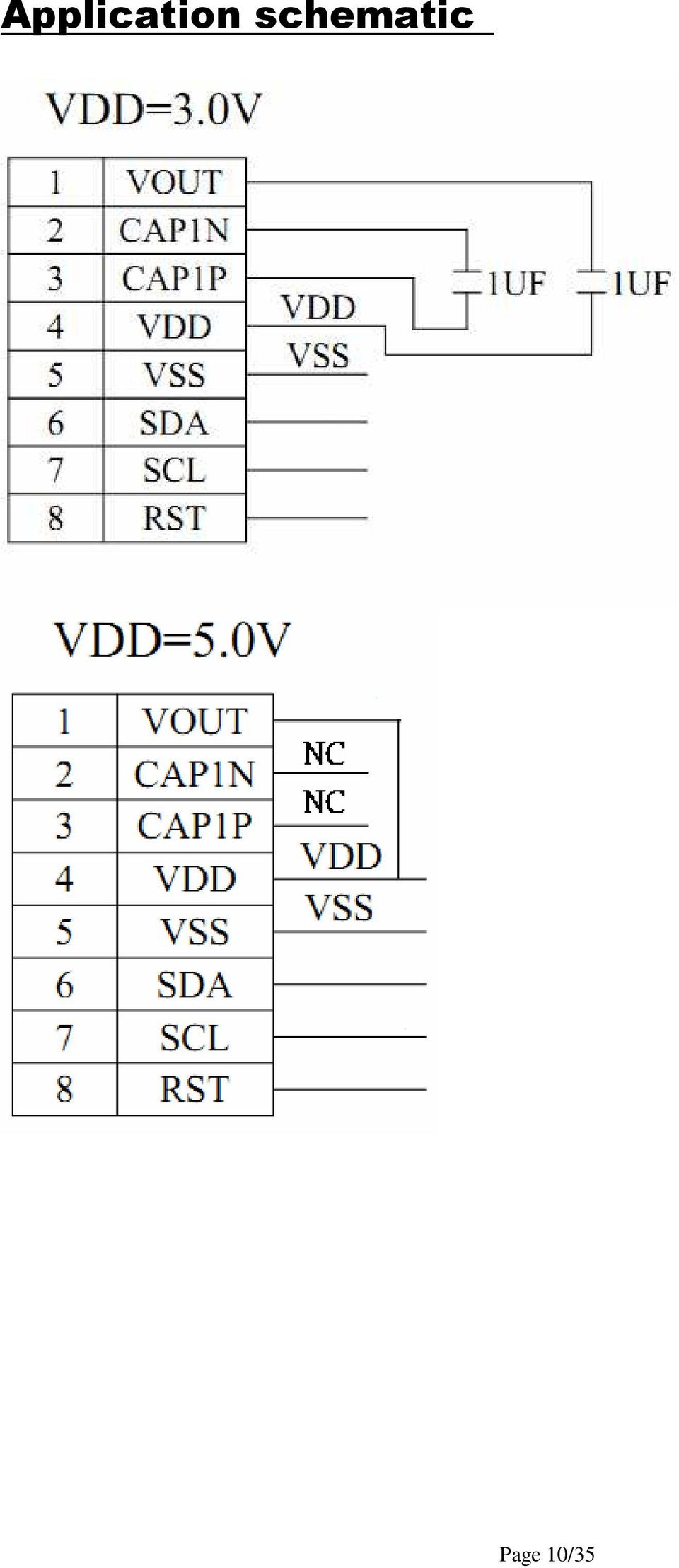
11 INITIALIZE: (3V) MOV I2C_CONTROL,#00H ;WRITE COMMAND MOV I2C_DATA,#38H ;Function Set LCALL WRITE_CODE MOV I2C_CONTROL,#00H ;WRITE COMMAND MOV I2C_DATA,#39H ;Function Set LCALL WRITE_CODE MOV I2C_DATA,#14H ;Internal OSC frequency LCALL WRITE_CODE MOV I2C_DATA,#74H ;Contrast set LCALL WRITE_CODE MOV I2C_DATA,#54H ;Power/ICON control/contrast set LCALL WRITE_CODE MOV I2C_DATA,#6FH ;Follower control LCALL WRITE_CODE MOV I2C_DATA,#0CH ;Display ON/OFF LCALL WRITE_CODE MOV I2C_DATA,#01H ;Clear Display LCALL WRITE_CODE Page 11/35

12 INITIALIZE: (5V) MOV I2C_CONTROL,#00H ;WRITE COMMAND MOV I2C_DATA,#38H ;Function Set LCALL MOV WRITE_CODE I2C_CONTROL,#00H ;WRITE COMMAND MOV I2C_DATA,#39H ;Function Set LCALL WRITE_CODE MOV I2C_DATA,#14H ;Internal OSC frequency LCALL WRITE_CODE MOV I2C_DATA,#79H ;Contrast set LCALL WRITE_CODE MOV I2C_DATA,#50H ;Power/ICON control/contrast set LCALL WRITE_CODE MOV I2C_DATA,#6CH ;Follower control LCALL WRITE_CODE MOV I2C_DATA,#0CH ;Display ON/OFF LCALL WRITE_CODE MOV I2C_DATA,#01H ;Clear Display LCALL WRITE_CODE Page 12/35

13 9.Function Description System Interface This chip has all four kinds of interface type with MPU: 4-bit bus, 8-bit bus. 4-bit bus or 8-bit bus is selected by DL bit in the instruction register. During read or write operation, two 8-bit registers are used. One is data register (DR); the other is instruction register (IR). The data register (DR) is used as temporary data storage place for being written into or read from DDRAM/CGRAM/ICON RAM, target RAM is selected by RAM address setting instruction. Each internal operation, reading from or writing into RAM, is done automatically. So to speak, after MPU reads DR data, the data in the next DDRAM/CGRAM/ICON RAM address is transferred into DR automatically. Also after MPU writes data to DR, the data in DR is transferred into DDRAM/CGRAM/ICON RAM automatically. The Instruction register (IR) is used only to store instruction code transferred from MPU. MPU cannot use it to read instruction data. Using RS input pin to select command or data in 4-bit/8-bit bus mode. I2C interface It just only could write Data or Instruction to ST7032 by the IIC Interface. It could not read Data or Instruction from ST7032 (except Acknowledge signal). SCL: serial clock input SDA: serial data input Slaver address could only set to , no other slaver address could be set The I2C interface send RAM data and executes the commands sent via the I2C Interface. It could send data bit to the RAM. The I2C Interface is two-line communication between different ICs or modules. The two lines are a Serial Data line (SDA) and a Serial Clock line (SCL). Both lines must be connected to a positive supply via a pull-up resistor. Data transfer may be initiated only when the bus is not busy. BIT TRANSFER One data bit is transferred during each clock pulse. The data on the SDA line must remain stable during the HIGH period of the clock pulse because changes in the data line at this time will be interpreted as a control signal. Bit transfer is illustrated in Fig.1. START AND STOP CONDITIONS Both data and clock lines remain HIGH when the bus is not busy. A HIGH-to-LOW transition of the data line, while the clock is HIGH is defined as the START condition (S). A LOW-to-HIGH transition of the data line while the clock is HIGH is defined as the STOP condition (P). The START and STOP conditions are illustrated in Fig.2. Page 13/35

14 SYSTEM CONFIGURATION The system configuration is illustrated in Fig.3. Transmitter: the device, which sends the data to the bus Master: the device, which initiates a transfer, generates clock signals and terminates a transfer Slave: the device addressed by a master Multi-Master: more than one master can attempt to control the bus at the same time without corrupting the message Arbitration: procedure to ensure that, if more than one master simultaneously tries to control the bus, only one is allowed to do so and the message is not corrupted Synchronization: procedure to synchronize the clock signals of two or more devices. ACKNOWLEDGE Acknowledge is not Busy Flag in I2C interface. Each byte of eight bits is followed by an acknowledge bit. The acknowledge bit is a HIGH signal put on the bus by the transmitter during which time the master generates an extra acknowledge related clock pulse. A slave receiver which is addressed must generate an acknowledge after the reception of each byte. A master receiver must also generate an acknowledge after the reception of each byte that has been clocked out of the slave transmitter. The device that acknowledges must pull-down the SDA line during the acknowledge clock pulse, so that the SDA line is stable LOW during the HIGH period of the acknowledge related clock pulse (set-up and hold times must be taken into consideration). A master receiver must signal an end-of-data to the transmitter by not generating an acknowledge on the last byte that has been clocked out of the slave. In this event the transmitter must leave the data line HIGH to enable the master to generate a STOP condition. Acknowledgement on the I2C Interface is illustrated in Fig.4. Page 14/35

15 I2C Interface protocol The ST7032 supports command, data write addressed slaves on the bus. Before any data is transmitted on the I2C Interface, the device, which should respond, is addressed first. Only one 7-bit slave addresses ( ) is reserved for the ST7032. The R/W is assigned to 0 for Write only. The I2C Interface protocol is illustrated in Fig.5. The sequence is initiated with a START condition (S) from the I2C Interface master, which is followed by the slave address. All slaves with the corresponding address acknowledge in parallel, all the others will ignore the I2C Interface transfer. After acknowledgement, one or more command words follow which define the status of the addressed slaves. A command word consists of a control byte, which defines Co and RS, plus a data byte. The last control byte is tagged with a cleared most significant bit (i.e. the continuation bit Co). After a control byte with a cleared Co bit, only data bytes will follow. The state of the RS bit defines whether the data byte is interpreted as a command or as RAM data. All addressed slaves on the bus also acknowledge the control and data bytes. After the last control byte, depending on the RS bit setting; either a series of display data bytes or command data bytes may follow. If the RS bit is set to logic 1, these display bytes are stored in the display RAM at the address specified by the data pointer. The data pointer is automatically updated and the data is directed to the intended ST7032i device. If the RS bit of the last control byte is set to logic 0, these command bytes will be decoded and the setting of the device will be changed according to the received commands. Only the addressed slave makes the acknowledgement after each byte. At the end of the transmission the I2C INTERFACE-bus master issues a STOP condition (P). Page 15/35

16 During write operation, two 8-bit registers are used. One is data register (DR), the other is instruction register (IR). The data register (DR) is used as temporary data storage place for being written into DDRAM/CGRAM/ICON RAM, target RAM is selected by RAM address setting instruction. Each internal operation, writing into RAM, is done automatically. So to speak, after MPU writes data to DR, the data in DR is transferred into DDRAM/CGRAM/ICON RAM automatically. The Instruction register (IR) is used only to store instruction code transferred from MPU. MPU cannot use it to read instruction data. To select register, use RS input in I2C interface. Busy Flag (BF) When BF = "High, it indicates that the internal operation is being processed. So during this time the next instruction cannot be accepted. BF can be read, when RS = Low and R/W = High (Read Instruction Operation), through DB7 port. Before executing the next instruction, be sure that BF is not High. Address Counter (AC) Address Counter (AC) stores DDRAM/CGRAM/ICON RAM address, transferred from IR. After writing into (reading from) DDRAM/CGRAM/ICON RAM, AC is automatically increased (decreased) by 1. Page 16/35
 is used only to store instruction code transferred from MPU. MPU cannot use it to read instruction data. To select register, use RS input in I2C interface.")
17 When RS = "Low" and R/W = "High", AC can be read through DB0 ~ DB6 ports. Display Data RAM (DDRAM) Display data RAM (DDRAM) stores display data represented in 8-bit character codes. Its extended capacity is 80 x 8 bits, or 80 characters. The area in display data RAM (DDRAM) that is not used for display can be used as general data RAM. See Figure 7 for the relationships between DDRAM addresses and positions on the liquid crystal display. The DDRAM address (ADD ) is set in the address counter (AC)as hexadecimal. Ø 1-line display (N = 0) (Figure 8) When there are fewer than 80 display characters, the display begins at the head position. For example, if using only the ST7032, 16 characters are displayed. See Figure 8. When the display shift operation is performed, the DDRAM address shifts. See Figure 9. Ø 2-line display (N = 1) (Figure 10) Case 1: When the number of display characters is less than 40 2 lines, the two lines are displayed from the head. Note that the first line end address and the second line start address are not consecutive. See Figure 10. Page 17/35
 (Figure 8) When there are fewer than 80 display characters, the display begins at the head position. For example, if using only the ST7032, 16 characters are displayed.")
18 Case 2: For a 16-character 2-line display See Figure 11. When display shift operation is performed, the DDRAM address shifts. See Figure 11. Page 18/35

19 Character Generator ROM (CGROM) The character generator ROM generates 5 x 8 dot character patterns from 8-bit character codes. It can generate 240/250/248/256 5 x 8 dot character patterns (select by OPR1/2 ITO pin). User-defined character patterns are also available by mask-programmed ROM. Character Generator RAM (CGRAM) In the character generator RAM, the user can rewrite character patterns by program. For 5 x 8 dots, eight character patterns can be written. Write into DDRAM the character codes at the addresses shown as the left column of Table 3 to show the character patterns stored in CGRAM. See Table 4 for the relationship between CGRAM addresses and data and display patterns. Areas that are not used for display can be used as general data RAM. ICON RAM In the ICON RAM, the user can rewrite icon pattern by program. There are totally 80 dots for icon can be written. See Table 5 for the relationship between ICON RAM address and data and the display patterns. Timing Generation Circuit The timing generation circuit generates timing signals for the operation of internal circuits such as DDRAM, CGROM and CGRAM. RAM read timing for display and internal operation timing by MPU access are generated separately to avoid interfering with each other. Therefore, when writing data to DDRAM, for example, there will be no undesirable interference, such as flickering, in areas other than the display area.(in I2C interface the reading function is invalid.) LCD Driver Circuit LCD Driver circuit has 17 common and 80 segment signals for LCD driving. Data from CGRAM/CGROM/ICON is transferred to 80 bit segment latch serially, and then it is stored to 80 bit shift latch. When each common is selected by 17 bit common register, segment data also output through segment driver from 80 bit segment latch. Cursor/Blink Control Circuit It can generate the cursor or blink in the cursor/blink control circuit. The cursor or the blink appears in the digit at the display data RAM address set in the address counter. Page 19/35

20 Page 20/35

21 Notes: 1. Character code bits 0 to 2 correspond to CGRAM address bits 3 to 5 (3 bits: 8 types). 2. CGRAM address bits 0 to 2 designate the character pattern line position. The 8th line is the cursor position and its display is formed by a logical OR with the cursor. Maintain the 8th line data, corresponding to the cursor display position, at 0 as the cursor display. If the 8th line data is 1, 1 bit will light up the 8th line regardless of the cursor presence. 3. Character pattern row positions correspond to CGRAM data bits 0 to 4 (bit 4 being at the left). 4. As shown Table 4, CGRAM character patterns are selected when character code bits 4 to 7 are all 0. However, since character code bit 3 has no effect, the R display example above can be selected by either character code 00H or 08H for CGRAM data corresponds to display selection and 0 to non-selection, - Indicates no effect. 6. Different OPR1/2 ITO option can select different CGRAM size. Page 21/35
22 Page 22/35
23 Instructions There are four categories of instructions that: Designate ST7032 functions, such as display format, data length, etc. Set internal RAM addresses Perform data transfer with internal RAM Others Page 23/35
24 instruction table at Normal mode Ø instruction table at Extension mode (when EXT option pin connect to VSS, the instruction set follow below table) Page 24/35
25 10.Instruction Description Clear all the display data by writing "20H" (space code) to all DDRAM address, and set DDRAM address to "00H" into AC (address counter). Return cursor to the original status, namely, bring the cursor to the left edge on first line of the display. Make entry mode increment (I/D = "1"). Return Home is cursor return home instruction. Set DDRAM address to "00H" into the address counter. Return cursor to its original site and return display to its original status, if shifted. Contents of DDRAM do not change. Set the moving direction of cursor and display. Ø I/D : Increment / decrement of DDRAM address (cursor or blink) When I/D = "High", cursor/blink moves to right and DDRAM address is increased by 1. When I/D = "Low", cursor/blink moves to left and DDRAM address is decreased by 1. * CGRAM operates the same as DDRAM, when read from or write to CGRAM. Ø S: Shift of entire display When DDRAM read (CGRAM read/write) operation or S = "Low", shift of entire display is not performed. If S = "High" and DDRAM write operation, shift of entire display is performed according to I/D value (I/D = "1": shift left, I/D = "0" : shift right). Page 25/35
26 Control display/cursor/blink ON/OFF 1 bit register. Ø D : Display ON/OFF control bit When D = "High", entire display is turned on. When D = "Low", display is turned off, but display data is remained in DDRAM. Ø C : Cursor ON/OFF control bit When C = "High", cursor is turned on. When C = "Low", cursor is disappeared in current display, but I/D register remains its data. Ø B : Cursor Blink ON/OFF control bit When B = "High", cursor blink is on, that performs alternate between all the high data and display character at the cursor position. When B = "Low", blink is off. Ø S/C: Screen/Cursor select bit When S/C= High, Screen is controlled by R/L bit. When S/C= Low, Cursor is controlled by R/L bit. Ø R/L: Right/Left When R/L= High, set direction to right. When R/L= Low, set direction to left. Without writing or reading of display data, shift right/left cursor position or display. This instruction is used to Page 26/35
27 correct or search display data. During 2-line mode display, cursor moves to the 2nd line after 40th digit of 1st line. Note that display shift is performed simultaneously in all the line. When displayed data is shifted repeatedly, each line shifted individually. When display shift is performed, the contents of address counter are not changed. Ø DL : Interface data length control bit When DL = "High", it means 8-bit bus mode with MPU. When DL = "Low", it means 4-bit bus mode with MPU. So to speak, DL is a signal to select 8-bit or 4-bit bus mode. When in 4-bit bus mode, it needs to transfer 4-bit data by two times. Ø N : Display line number control bit When N = "High", 2-line display mode is set. When N = "Low", it means 1-line display mode. Ø DH : Double height font type control bit When DH = " High " and N= Low, display font is selected to double height mode(5x16 dot),ram address can only use 00H~27H. When DH= High and N= High, it is forbidden. When DH = " Low ", display font is normal (5x8 dot). Page 27/35
28 Ø IS : normal/extension instruction select When IS= High, extension instruction be selected (refer extension instruction table) When IS= Low, normal instruction be selected (refer normal instruction table) Set CGRAM address to AC. This instruction makes CGRAM data available from MPU. Set DDRAM address to AC. This instruction makes DDRAM data available from MPU. When 1-line display mode (N = 0), DDRAM address is from "00H" to "4FH". In 2-line display mode (N = 1), DDRAM address in the 1st line is from "00H" to "27H", and DDRAM address in the 2nd line is from "40H" to "67H". When BF = High, indicates that the internal operation is being processed. So during this time the next instruction cannot be accepted. Page 28/35
29 The address Counter (AC) stores DDRAM/CGRAM addresses, transferred from IR. After writing into (reading from) DDRAM/CGRAM, AC is automatically increased (decreased) by 1. Write binary 8-bit data to CGRAM, DDRAM or ICON RAM The selection of RAM from DDRAM, CGRAM or ICON RAM, is set by the previous address set instruction : DDRAM address set, CGRAM address set, ICON RAM address set. RAM set instruction can also determine the AC direction to RAM. After write operation, the address is automatically increased/decreased by 1, according to the entry mode. Read binary 8-bit data from DDRAM/CGRAM/ICON RAM The selection of RAM is set by the previous address set instruction. If address set instruction of RAM is not performed before this instruction, the data that read first is invalid, because the direction of AC is not determined. If you read RAM data several times without RAM address set instruction before read operation, you can get correct RAM data from the second, but the first data would be incorrect, because there is no time margin to transfer RAM data. Read data must be set address before this instruction. Ø BS: bias selection When BS= High, the bias will be 1/4 When BS= Low, the bias will be 1/5 BS will be invalid when external bias resistors are used (OPF1=1, OPF2=1) Ø F2,F1,F0 : Internal OSC frequency adjust When CLS connect to high, that instruction can adjust OSC and Frame frequency. Page 29/35
30 Set ICON RAM address to AC. This instruction makes ICON data available from MPU. When IS=1 at Extension mode, The ICON RAM address is from "00H" to "0FH". Ø Ion: set ICON display on/off When Ion = "High", ICON display on. When Ion = "Low", ICON display off. Ø Bon: switch booster circuit Bon can only be set when internal follower is used (OPF1=0, OPF2=0). When Bon = "High", booster circuit is turn on. When Bon = "Low", booster circuit is turn off. Ø C5,C4 : Contrast set(high byte) C5,C4,C3,C2,C1,C0 can only be set when internal follower is used (OPF1=0,OPF2=0).They can more precisely adjust the input reference voltage of V0 generator. The details please refer to the supply voltage for LCD driver. Ø Fon: switch follower circuit Fon can only be set when internal follower is used (OPF1=0,OPF2=0). When Fon = "High", internal follower circuit is turn on. When Fon = "Low", internal follower circuit is turn off. Page 30/35
31 Ø Rab2,Rab1,Rab0 : V0 generator amplified ratio Rab2,Rab1,Rab0 can only be set when internal follower is used (OPF1=0,OPF2=0).They can adjust the amplified ratio of V0 generator. The details please refer to the supply voltage for LCD driver. Ø C3,C2,C1,C0:Contrast set(low byte) C5,C4,C3,C2,C1,C0 can only be set when internal follower is used (OPF1=0,OPF2=0).They can more precisely adjust the input reference voltage of V0 generator. The details please refer to the supply voltage for LCD driver. Page 31/35
32 11.Reliability Content of Reliability Test (wide temperature, -20 ~70 ) Note1: No dew condensation to be observed. Environmental Test Test Item Content of Test Test Condition Note High Temperature Endurance test applying the high storage 80 storage temperature for a long time. 200hrs 2 Low Temperature Endurance test applying the high storage -30 storage temperature for a long time. 200hrs 1,2 Endurance test applying the electric stress High Temperature 70 (Voltage & Current) and the thermal stress to the Operation element for a long time. 200hrs Low Temperature Operation High Temperature/ Humidity Operation Thermal shock resistance Vibration test Static electricity test Endurance test applying the electric stress under low temperature for a long time. The module should be allowed to stand at 60,90%RH max For 96hrs under no-load condition excluding the polarizer, Then taking it out and drying it at normal temperature. The sample should be allowed stand the following 10 cycles of operation min 5min 30min 1 cycle Endurance test applying the vibration during transportation and using. Endurance test applying the electric stress to the terminal. Note2: The function test shall be conducted after 4 hours storage at the normal Temperature and humidity after remove from the test chamber. Note3: Vibration test will be conducted to the product itself without putting it in a container. Page 32/ hrs 60,90%RH 96hrs -20 /70 10 cycles Total fixed amplitude : 1.5mm Vibration Frequency : 10~55Hz One cycle 60 seconds to 3 directions of X,Y,Z for Each 15 minutes VS=800V,RS=1.5k Ω CS=100pF 1 time 1 1,2 3
33 12.Backlight Information Specification PARAMETER SYMBOL MIN TYP MAX UNIT TEST CONDITION Supply Current ILED ma V=3.5V Supply Voltage V V Reverse Voltage VR V - Luminous Intensity (Without LCD) IV CD/M 2 ILED=32mA LED Life Time Hr. ILED 32mA Color White Note: The LED of B/L is drive by current only;driving voltage is only for reference To make driving current in safety area (waste current between minimum and maximum). Note1 :50K hours is only an estimate for reference. LED B\L Drive Method Drive from A, K R A K B/L Page 33/35
34 13. Inspection specification NO Item Criterion AQL 01 Electrical Testing 1.1 Missing vertical, horizontal segment, segment contrast defect. 1.2 Missing character, dot or icon. 1.3 Display malfunction. 1.4 No function or no display. 1.5 Current consumption exceeds product specifications. 1.6 LCD viewing angle defect. 1.7 Mixed product types. 1.8 Contrast defect Black or white spots on LCD (display only) 2.1 White and black spots on display 0.25mm, no more than three white or black spots present. 2.2 Densely spaced: No more than two spots or lines within 3mm 3.1 Round type : As following drawing Φ=( x + y ) / 2 SIZE Acceptable Q TY Φ 0.10 Accept no dense 0.10<Φ LCD black spots, white spots, contamination (non-display) 0.20<Φ <Φ Line type : (As following drawing) Length Width Acceptable Q TY --- W 0.02 Accept no dense L 3.0 L 0.02<W <W <W As round type 04 Polarizer bubbles If bubbles are visible, judge using black spot specifications, not easy to find, must check in specify direction. Size Φ Acceptable Q TY Φ 0.20 Accept no dense 0.20<Φ <Φ <Φ 0 Total Q TY 3 Page 34/35
35 NO Item Criterion AQL 05 Scratches Follow NO.3 LCD black spots, white spots, contamination Symbols Define: x: Chip length y: Chip width z: Chip thickness k: Seal width t: Glass thickness a: LCD side length L: Electrode pad length: 6.1 General glass chip : Chip on panel surface and crack between panels: z: Chip thickness y: Chip width x: Chip length 06 Chipped glass Z 1/2t Not over viewing x 1/8a area 1/2t<z 2t Not exceed 1/3k x 1/8a If there are 2 or more chips, x is total length of each chip Corner crack: z: Chip thickness y: Chip width x: Chip length Z 1/2t Not over viewing x 1/8a area 1/2t<z 2t Not exceed 1/3k x 1/8a If there are 2 or more chips, x is the total length of each chip. Page 35/35
36 NO Item Criterion AQL Symbols : x: Chip length y: Chip width z: Chip thickness k: Seal width t: Glass thickness a: LCD side length L: Electrode pad length 6.2 Protrusion over terminal : Chip on electrode pad : y: Chip width x: Chip length z: Chip thickness y 0.5mm x 1/8a 0 < z t Non-conductive portion: 06 Glass crack y: Chip width x: Chip length z: Chip thickness y L x 1/8a 0 < z t If the chipped area touches the ITO terminal, over 2/3 of the ITO must remain and be inspected according to electrode terminal specifications. If the product will be heat sealed by the customer, the alignment mark not be damaged Substrate protuberance and internal crack. y: width x: length y 1/3L x a Page 36/35
37 NO Item Criterion AQL 07 Cracked glass The LCD with extensive crack is not acceptable. 08 Backlight elements 8.1 Illumination source flickers when lit. 8.2 Spots or scratched that appear when lit must be judged. Using LCD spot, lines and contamination standards. 8.3 Backlight doesn t light or color wrong Bezel 9.1 Bezel may not have rust, be deformed or have fingerprints, stains or other contamination. 9.2 Bezel must comply with job specifications PCB COB 10.1 COB seal may not have pinholes larger than 0.2mm or contamination COB seal surface may not have pinholes through to the IC The height of the COB should not exceed the height indicated in the assembly diagram There may not be more than 2mm of sealant outside the seal area on the PCB. And there should be no more than three places No oxidation or contamination PCB terminals Parts on PCB must be the same as on the production characteristic chart. There should be no wrong parts, missing parts or excess parts The jumper on the PCB should conform to the product characteristic chart If solder gets on bezel tab pads, LED pad, zebra pad or screw hold pad, make sure it is smoothed down The Scraping testing standard for Copper Coating of PCB Y X X * Y<=2mm 2 11 Soldering 11.1 No un-melted solder paste may be present on the PCB No cold solder joints, missing solder connections, oxidation or icicle No residue or solder balls on PCB No short circuits in components on PCB Page 37/35
38 NO Item Criterion AQL 12 General appearance 12.1 No oxidation, contamination, curves or, bends on interface Pin (OLB) of TCP No cracks on interface pin (OLB) of TCP No contamination, solder residue or solder balls on product The IC on the TCP may not be damaged, circuits. 1 The uppermost edge of the protective strip on the interface pin must be present or look as if it cause the interface pin to sever The residual rosin or tin oil of soldering (component or chip component) is not burned into brown or black color Sealant on top of the ITO circuit has not hardened Pin type must match type in specification sheet LCD pin loose or missing pins Product packaging must the same as specified on packaging specification sheet Product dimension and structure must conform to product specification sheet Page 38/35
39 14. Material List of Components for RoHs 1. WINSTAR Display Co., Ltd hereby declares that all of or part of products (with the mark # in code), including, but not limited to, the LCM, accessories or packages, manufactured and/or delivered to your company (including your subsidiaries and affiliated company) directly or indirectly by our company (including our subsidiaries or affiliated companies) do not intentionally contain any of the substances listed in all applicable EU directives and regulations, including the following substances.. Exhibit A:The Harmful Material List Material (Cd) (Pb) (Hg) (Cr6+) PBBs PBDEs Limited Value 100 ppm 1000 ppm 1000 ppm 1000 ppm 1000 ppm 1000 ppm Above limited value is set up according to RoHS. 2.Process for RoHS requirement: (1) Use the Sn/Ag/Cu soldering surface;the surface of Pb-free solder is rougher than we used before. (2) Heat-resistance temp.: Reflow:250,30 seconds Max. ; Connector soldering wave or hand soldering:320, 10 seconds max. (3) Temp. curve of reflow, max. Temp.:235±5 ; Recommended customer s soldering temp. of connector:280, 3 seconds. 15. Recommendable storage 1. Place the panel or module in the temperature 25 C±5 C and the humidity below 65% RH 2. Do not place the module near organics solvents or corrosive gases. 3. Do not crush, shake, or jolt the module Page 39/35
40 LCM Sample Estimate Feedback Sheet winstar Module Number: Page: 1 1 Panel Specification: 1. Panel Type: Pass NG, 2. View Direction: Pass NG, 3. Numbers of Dots: Pass NG, 4. View Area: Pass NG, 5. Active Area: Pass NG, 6. Operating Temperature: Pass NG, 7. Storage Temperature: Pass NG, 8. Others: 2 Mechanical Specification: 1. PCB Size: Pass NG, 2. Frame Size: Pass NG, 3. Materal of Frame: Pass NG, 4. Connector Position: Pass NG, 5. Fix Hole Position:A Pass NG, 6. Backlight Position: Pass NG, 7. Thickness of PCB: Pass NG, 8. Height of Frame to PCB: Pass NG, 9. Height of Module: Pass NG, 10. Others: Pass NG, 3 Relative Hole Size: 1. Pitch of Connector: Pass NG, 2. Hole size of Connector: Pass NG, 3. Mounting Hole size: Pass NG, 4. Mounting Hole Type: Pass NG, 5. Others: Pass NG, 4 Backlight Specification: 1. B/L Type: Pass NG, 2. B/L Color: Pass NG, 3. B/L Driving Voltage (Reference for LED Type): Pass NG, 4. B/L Driving Current: Pass NG, 5. Brightness of B/L: Pass NG, 6. B/L Solder Method: Pass NG, 7. Others: Pass NG, >> Go to page 2 << Page 40/35
41 winstar Module Number: Page: 2 5 Electronic Characteristics of Module: 1. Input Voltage: Pass NG, 2. Supply Current: Pass NG, 3. Driving Voltage for LCD: Pass NG, 4. Contrast for LCD: Pass NG, 5. B/L Driving Method: Pass NG, 6. Negative Voltage Output: Pass NG, 7. Interface Function: Pass NG, 8. LCD Uniformity: Pass NG, 9. ESD test: Pass NG, 10. Others: Pass NG, 6 Summary: Sales signature: Customer Signature: Date: / / Page 41/35
Winstar Display Co., LTD 華 凌 光 電 股 份 有 限 公 司 住 址 : 407 台 中 市 中 清 路 163 號
 Winstar Display Co., LTD 華 凌 光 電 股 份 有 限 公 司 住 址 : 47 台 中 市 中 清 路 163 號 No.163 Chung Ching RD., Taichune, Taiwan, R.O.C WEB: http://www.winstar.com.tw E-mail: winstar@winstar.com.tw Tel:886-4-2426228 Fax:886-4-2426227
How To Use A Gmbh Gmbhl-E2A (Gmbh-E1) (Gbh-A2A) (Gebh) (For A Test Drive) (Solder) (Powerboard
 (Gbh-A2A) (Gebh) (For A Test Drive) (Solder) (Powerboard") Gleichmann & Co. Electronics GmbH Industriestrasse 16 76297 Stutensee-Spöck / Germany CUSTOMER : SPECIFICATION MODULE NO.: GE-C162B-TMI-JT/R APPROVED BY: ( FOR CUSTOMER USE ONLY ) PCB VERSION: DATA: SALES
Gleichmann & Co. Electronics GmbH Industriestrasse 16 76297 Stutensee-Spöck / Germany CUSTOMER : SPECIFICATION MODULE NO.: GE-C162B-TMI-JT/R APPROVED BY: ( FOR CUSTOMER USE ONLY ) PCB VERSION: DATA: SALES
LCD Module User Manual
 LCD Module User Manual Customer : Ordering Code DRAWING NO : TC1602D-02WB0 : m-tc1602d-02wb0_a00 Approved By Customer: Date: Approved By Checked By Prepared By LET (HK) PACIFIC CO, LTD ADD:Flat B1,5/F,Yip
WEB: http://www.raystar-optronics.com E-mail: sales@raystar-optronics.com Tel:886-4-2565-0761 Fax:886-4-2565-0760 SPECIFICATION
 曜 凌 光 電 股 份 有 限 公 司 住 址 : 42878 台 中 縣 大 雅 鄉 科 雅 路 25 號 5F 5F, No.25, keya Rd. Daya Township, Taichung County, Taiwan RC24A-BIW-ESX WEB: http://www.raystar-optronics.com E-mail: sales@raystar-optronics.com
MGL5128 128x64 Graphic LCD Module User Manual
 MGL5128 128x64 Graphic LCD Module User Manual Version: 1.0.0 January 2005 Table of Contents I Precautions in use of LCD Modules 2 II General Specification 2 III Absolute Maximum Ratings 2 IV Electrical
WEB: http://www.raystar-optronics.com E-mail: sales@raystar-optronics.com Tel:886-4-2565-0761 Fax:886-4-2565-0760 SPECIFICATION
 曜 凌 光 電 股 份 有 限 公 司 住 址 : 42878 台 中 縣 大 雅 鄉 科 雅 路 25 號 5F 5F, No.25, keya Rd. Daya Township, Taichung County, Taiwan WEB: http://www.raystar-optronics.com E-mail: sales@raystar-optronics.com Tel:886-4-2565-761
LCD MODULE SPECIFICATION MODEL NO. BG12864EFPHHn
 LCD MODULE SPECIFICATION MODEL NO. BG12864EFPHHn FOR MESSRS: ON DATE OF: APPROVED BY: C O N T E N T S 1. Numbering System 2. General Specification 3. Absolute Maximum Ratings 4. Electrical Characteristics
WEB: http://www.raystar-optronics.com E-mail: sales@raystar-optronics.com Tel:886-4-22911297 Fax:886-4-22911296 SPECIFICATION
 曜 凌 光 電 股 份 有 限 公 司 住 址 : 406 台 中 市 敦 化 路 456 號 6F No.456-6, Dunhua RD., Beitun District,Taichung, Taiwan, R.O.C RC1602B-GHY-CSXD WEB: http://www.raystar-optronics.com E-mail: sales@raystar-optronics.com
LMB162ABC LCD Module User Manual
 LMB162ABC LCD Module User Manual Shenzhen TOPWAY Technology Co., Ltd. Rev. Descriptions Release Date 0.1 Prelimiay release 2005-03-17 0.2 Typing Correction in 1.3 Block Diagram 2007-05-06 URL Document
SPECIFICATIONS FOR LIQUID CRYSTAL DISPLAY
 SPECIFICATIONS FOR LIQUID CRYSTAL DISPLAY PART NUMBER: MGD1602B DATE: MAR. 17,2004 1.0 MECHANICAL SPECS 1. Overall Module Size 84.0mm(W) x 44.0mm(H) x max 13.5mm(D) for LED backlight version 84.0mm(W)
GDM1602A SPECIFICATIONS OF LCD MODULE. Features. Outline dimension
 SPECIFICATIONS OF LCD MODULE Features 1. 5x8 dots 2. Built-in controller (S6A0069 or Equivalent) 3. Power supply: Type 5V 4. 1/16 duty cycle 5. LED backlight 6. N.V. option Outline dimension Absolute maximum
LCD MODULE DEM 16217 SYH-LY
 Display Elektronik GmbH LCD MODULE DEM 16217 SYH-LY Product specification Version : 5 14.04.2003 GENERAL SPECIFICATION MODULE NO. : DEM 16217 SYH-LY CUSTOMER P/N VERSION NO. CHANGE DESCRIPTION DATE 0 ORIGINAL
EMERGING DISPLAY CUSTOMER ACCEPTANCE SPECIFICATIONS 16290(LED TYPES) EXAMINED BY : FILE NO. CAS-10251 ISSUE : JUL.03,2001 TOTAL PAGE : 7
 EXAMINED BY : FILE NO. CAS-10251 ISSUE : JUL.03,2001 TOTAL PAGE : 7") EXAMINED BY : FILE NO. CAS-10251 EMERGING DISPLAY ISSUE : JUL.03,2001 APPROVED BY: TECHNOLOGIES CORPORATION TOTAL PAGE : 7 VERSION : 1 CUSTOMER ACCEPTANCE SPECIFICATIONS MODEL NO. : 16290(LED TYPES) FOR
EXAMINED BY : FILE NO. CAS-10251 EMERGING DISPLAY ISSUE : JUL.03,2001 APPROVED BY: TECHNOLOGIES CORPORATION TOTAL PAGE : 7 VERSION : 1 CUSTOMER ACCEPTANCE SPECIFICATIONS MODEL NO. : 16290(LED TYPES) FOR
LCD MODULE DEM 16481 SYH-LY
 DISPLAY Elektronik GmbH LCD MODULE DEM 16481 SYH-LY Version :1.1.1 16/Jan/2009 GENERAL SPECIFICATION MODULE NO. : DEM 16481 SYH-LY CUSTOMER P/N VERSION NO. CHANGE DESCRIPTION DATE 0 ORIGINAL VERSION 16.01.2001
EMERGING DISPLAY CUSTOMER ACCEPTANCE SPECIFICATIONS 16400(LED TYPES) EXAMINED BY : FILE NO. CAS-10068 ISSUE : JAN.19,2000 TOTAL PAGE : 7 APPROVED BY:
 EXAMINED BY : FILE NO. CAS-10068 ISSUE : JAN.19,2000 TOTAL PAGE : 7 APPROVED BY:") EXAMINED BY : FILE NO. CAS-10068 APPROVED BY: EMERGING DISPLAY TECHNOLOGIES CORPORATION ISSUE : JAN.19,2000 TOTAL PAGE : 7 VERSION : 3 CUSTOMER ACCEPTANCE SPECIFICATIONS MODEL NO. : 16400(LED TYPES) FOR
EXAMINED BY : FILE NO. CAS-10068 APPROVED BY: EMERGING DISPLAY TECHNOLOGIES CORPORATION ISSUE : JAN.19,2000 TOTAL PAGE : 7 VERSION : 3 CUSTOMER ACCEPTANCE SPECIFICATIONS MODEL NO. : 16400(LED TYPES) FOR
C 2011/6/17 21 Modify backlight information.
 Gleichmann & Co. Electronics GmbH Industriestrasse 16 76297 Stutensee-Spöck / Germany SPECIFICATION CUSTOMER : MODULE NO.: GE-C1602B-TFH-JT/R APPROVED BY: ( FOR CUSTOMER USE ONLY ) PCB VERSION: DATA: SALES
EMERGING DISPLAY CUSTOMER ACCEPTANCE SPECIFICATIONS 20400 (LED TYPES) EXAMINED BY : FILE NO. CAS-10184 ISSUE : DEC.01,1999 TOTAL PAGE : 7 APPROVED BY:
 EXAMINED BY : FILE NO. CAS-10184 ISSUE : DEC.01,1999 TOTAL PAGE : 7 APPROVED BY:") EXAMINED BY : FILE NO. CAS-10184 APPROVED BY: EMERGING DISPLAY TECHNOLOGIES CORPORATION ISSUE : DEC.01,1999 TOTAL PAGE : 7 VERSION : 2 CUSTOMER ACCEPTANCE SPECIFICATIONS MODEL NO. : 20400 (LED TYPES) FOR
EXAMINED BY : FILE NO. CAS-10184 APPROVED BY: EMERGING DISPLAY TECHNOLOGIES CORPORATION ISSUE : DEC.01,1999 TOTAL PAGE : 7 VERSION : 2 CUSTOMER ACCEPTANCE SPECIFICATIONS MODEL NO. : 20400 (LED TYPES) FOR
SPECIFICATION CUSTOMER : APPROVED BY: ( FOR CUSTOMER USE ONLY ) SALES BY APPROVED BY CHECKED BY PREPARED BY ISSUED DATE:
 SALES BY APPROVED BY CHECKED BY PREPARED BY ISSUED DATE:") SPECIFICATION CUSTOMER : MODULE NO.: PH216B-BYB-E APPROVED BY: ( FOR CUSTOMER USE ONLY ) SALES BY APPROVED BY CHECKED BY PREPARED BY ISSUED DATE: Contents 1.Module Classification Information 2.Precautions
SPECIFICATION CUSTOMER : MODULE NO.: PH216B-BYB-E APPROVED BY: ( FOR CUSTOMER USE ONLY ) SALES BY APPROVED BY CHECKED BY PREPARED BY ISSUED DATE: Contents 1.Module Classification Information 2.Precautions
Contents & P-LCD Modules Cross Reference Table
 Contents & P-LCD Modules Cross Reference Table Contents Contents & P-LCD Modules Cross Reference Table Introduction & Standard P-LCD Modules Modes Custom P-LCD Modules Standard Design P-LCD Modules (Character
LCD MODULE DEM 08202 SYH-LY
 Display Elektronik GmbH LCD MODULE DEM 08202 SYH-LY Product Specification Version : 1.1.0 29/Dec./2007 DOCUMENT REVISION HISTORY Version DATE DESCRIPTION CHANGED BY 0 20.07.2005 First issue MHO 1.1.0 29.11.2007
LCM NHD-12032BZ-FSW-GBW. User s Guide. (Liquid Crystal Display Graphic Module) RoHS Compliant. For product support, contact
 RoHS Compliant. For product support, contact") User s Guide -FSW-GBW LCM (Liquid Crystal Display Graphic Module) RoHS Compliant NHD- 12032- BZ- F - SW- G- B- W- Newhaven Display 120 x 32 pixels Version Line Transflective Side White LED B/L STN- Gray
User s Guide -FSW-GBW LCM (Liquid Crystal Display Graphic Module) RoHS Compliant NHD- 12032- BZ- F - SW- G- B- W- Newhaven Display 120 x 32 pixels Version Line Transflective Side White LED B/L STN- Gray
HD44780-Based LCD Modules. Introduction to the LM018L
 HD44780-Based LCD Modules Hitachi LM018L 40 character x 2 lines Built-in LSI HD44780 controller +5volt single power supply Display Colour: Grey LM018L: Introduction Interfacing Display Pattern and Character
LCD MODULE DEM 128064B FGH-PW
 DISPLAY Elektronik GmbH LCD MODULE DEM 128064B FGHPW Version : 2.1.1 30.09.2008 GENERAL SPECIFICATION MODULE NO. : DEM 128064B FGHPW VERSION NO. CHANGE DESCRIPTION DATE 0 ORIGINAL VERSION 27.11.2006 1
Microtips Technology Inc. 台 北 縣 汐 止 鎮 康 寧 街 169 巷 31 號 12 樓 12F, No 31, Lane 169, Kang Ning St. Hsi-Chih, Taipei Hsien, Taiwan, R.O.C.
 Microtips Technology Microtips Technology Inc. 台 北 縣 汐 止 鎮 康 寧 街 169 巷 31 號 12 樓 12F, No 31, Lane 169, Kang Ning St. Hsi-Chih, Taipei Hsien, Taiwan, R.O.C. WEB : http://www.microtips.com.tw E-mail : Macros@microtips.com.tw
FOR MESSRS. : WC1602A PAGE: 1/12 CONTENTS
 T h e L C D ( M ) S p e c i a l i s t CONTACT ADDRESS : 6F, Block 105, Jin Di Industrial Park, Fu Qiang Rd. Fu Tian, Shenzhen City,China. Tel: 0086-755-83308729 Fax: 0086-755-83308659 E-mail: craig.jiang@wincomlcd.com
Revision History. Date Page Summary. Approved By: Document Number: OG24161 r.0 Page 1 of 11
 Tel: (972) 437-3888 Fax: (972)437-2562 Email: lcd@ocularlcd.com LCD Graphic STN Module Specification Model: OG24161 Table of Contents 1 Construction and Outline...2 2 Module Specifications...2 Table 1
AZ DISPLAYS, INC. LCD MODULE SPECIFICATION MODULE TYPE : AGM1616A
 AZ DISPLAYS, INC. LCD MODULE SPECIFICATION MODULE TYPE : AGM1616A SPECIFICATION FOR LIQUID CRYSTAL DISPLAY MODULE View Direction 6 O clock 12 O clock LCD Type FSTN Positive STN Gray FSTN Negative STN Yellow
NHD C0220BiZ FSW FBW 3V3M
 NHD C0220BiZ FSW FBW 3V3M COG (Chip On Glass) Character Liquid Crystal Display Module NHD Newhaven Display C0220 COG, 2 Lines x 20 Characters BiZ Model, I 2 C interface F Transflective SW Side White LED
Specification. For. LCD Module CCM1620CSL
 Specification For LCD Module CCM1620CSL 1 FEATURES CASIL SEMICONDUCTOR CO., LTD. CCM1620CSL LCD MODULE Display Type: STN Display Format: 16 Characters x 2 Lines Input Data: 4-Bits or 8-Bits interface available
HD44780U (LCD-II) (Dot Matrix Liquid Crystal Display Controller/Driver)
 (Dot Matrix Liquid Crystal Display Controller/Driver)") HD4478U (LCD-II) (Dot Matrix Liquid Crystal Display Controller/Driver) Description The HD4478U dot-matrix liquid crystal display controller and driver LSI displays alphanumerics, Japanese kana characters,
HD4478U (LCD-II) (Dot Matrix Liquid Crystal Display Controller/Driver) Description The HD4478U dot-matrix liquid crystal display controller and driver LSI displays alphanumerics, Japanese kana characters,
LCD MODULE SPECIFICATION MODEL NO. BC1602E series
 LCD MODULE SPECIFICATION MODEL NO. BC1602E series FOR MESSRS: ON DATE OF: APPROVED BY: C O N T E N T S 1. Numbering System 2. Precautions in use of LCD Modules 3. General Specification 4. Absolute Maximum
TFT LCD Specification. Model NO.: OSD080TN42
 310 Genius Drive Winter Park, FL 32789 Phone: 407-629-0500 Fax: 407-645-5376 sales@osddisplays.com www.osddisplays.com TFT LCD Specification Model NO.: OSD080TN42 Customer Signature Date Record of Revision
SPECIFICATIONS FOR LCD MODULE
 A M P I R E SPECIFICATIONS FOR LCD MODULE CUSTOMER CUSTOMER PART NO. AMPIRE PART NO. -162B APPROVED BY DATE APPROVED BY CHECKED BY ORGANIZED BY AMPIRE CO., LTD. 1 RECORD OF REVISION Revision Date Page
Sitronix Preliminary ST7036. Features
 ST Sitronix Preliminary ST7036 Dot Matrix LCD Controller/Driver Features 5 x 8 dot matrix possible Low power operation support: -- 2.7 to 5.5V Range of LCD driver power -- 2.7 to 7.0V 4-bit, 8-bit, serial
-SFYLYHTC06 FOR MESSRS. :
 T h e L C D ( M ) S p e c i a l i s t CONTACT ADDRESS : 6F, Block 105, Jing Di Industrial Park, Fu Qiang Rd. Fu Tian, Shenzhen City,China. Tel: 0086-755-83308729 Fax: 0086-755-83308659 E-mail: craig.jiang@wincomlcd.com
BATRON DOCUMENT NUMBER AND REVISION VL-FS-BTHQ 21605VSS-02 REV.A (BTHQ 21605VSS-FSTF-LED05W(1 DIE)) Feb/2002 BTHQ 21605-FSTF-LED WHITE 1/15
) Feb/2002 BTHQ 21605-FSTF-LED WHITE 1/15") Feb/2002 1/15 DOCUMENT NUMBER AND REVISION VL-FS-BTHQ 21605VSS-02 REV.A (BTHQ 21605VSS-FSTF-LED05W(1 DIE)) 2/15 DOCUMENT REVISION HISTORY 1: DOCUMENT REVISION DATE DESCRIPTION CHANGED BY FROM TO A 2002.01.09
Feb/2002 1/15 DOCUMENT NUMBER AND REVISION VL-FS-BTHQ 21605VSS-02 REV.A (BTHQ 21605VSS-FSTF-LED05W(1 DIE)) 2/15 DOCUMENT REVISION HISTORY 1: DOCUMENT REVISION DATE DESCRIPTION CHANGED BY FROM TO A 2002.01.09
NHD-0420D3Z-FL-GBW-V3
 NHD-0420D3Z-FL-GBW-V3 Serial Liquid Crystal Display Module NHD- Newhaven Display 0420-4 Lines x 20 Characters D3Z- Model F- Transflective L- Yellow/Green LED Backlight G- STN-Gray B- 6:00 Optimal View
LIQUID CRYSTAL DISPLAY MODULE MODEL: MTG-E8619-A3 Customer s No.:
 A Nov. 05, 05 1 / 21 LIQUID CRYSTAL DISPLAY MODULE MODEL: MTG-E8619-A3 Customer s No.: Acceptance Approved and Checked by Approved by Checked by Made by 2005/11/5 2005/11/5 2005/11/5 2005/11/5 A Nov. 05,
OPTREX CORP. LCD MODULE
 MITSUBISHI INTERNATIONAL GMBH OPTREX CORP. LCD MODULE ALPHANUMERIC TYPE DMC SERIES USER S MANUAL FOR LCD MODULE WITH CONTROLLER HITACHI HD44780 Mitsubishi International GmbH Kennedydamm 19 D-40476 Düsseldorf
NT7606. STN LCDController/Driver. RAM-Map STN LCD Controller/Driver. Preliminary
 16C Characters X 3L Character X 3 Lines + 80 + icon 80 icons RAM-Map STN LCD Controller/Driver STN LCDController/Driver V0.04 V1.0 Preliminary Revision History...3 Features...4 General Description...4
EA DOGS104x-A INCL. CONTROLLER SSD1803A FOR SPI AND I²C. available at 1 piece! Switchable font height ACCESSORIES
 Issue 7.2015 EA DOGS104-A INCL. CONTROLLER SSD1803A FOR SPI AND I²C available at 1 piece! Switchable font height Dimension 36,0 x 27.5 x 4.6 mm TECHNICAL DATA * HIGH-CONTRAST LCD SUPERTWIST DISPLAY * OPTIONAL
Product Specification C216x01 series
 Product Specification C216x01 series Crystal Clear Technology sdn. bhd. 16Jalan TP5 Taman Perindustrian Sime UEP 47600 Subang Jaya Selangor DE Malaysia. T: +603 80247099 F: +603 80247098 1.0 Table of Contents
SPECIFICATION OF LCD MODULE
 SPECIFICATION OF LCD MODULE CUSTOMER 客 户 名 称 PART NO. 产 品 型 号 PRODUCTS TYPE 产 品 内 容 JHD162a-YG 659Y-YG REMARKS 备 注 SIGNATURE BY CUSTOMER 客 户 签 署 : 深 圳 市 晶 汉 达 电 子 有 限 公 司 08 年 11 月 17 日 Page: 1 LCM System
LCM MODULE TC1602A-09I 120422
 LCM MODULE TC1602A-09I 120422 Specification for Approval APPROVED BY CHECKED BY PREPARED BY ISSUED: V00 2011-06-07 CONTENTS FUNCTIONS & FEATURES ----------------------------------------------------------------------------------------------------------
SPECIFICATIONS FOR LCD MODULE
 SPECIFICATIONS FOR LCD MODULE MODEL NO. BC2004A series VER.01 FOR MESSRS: ON DATE OF: APPROVED BY: BOLYMIN, INC. 13F-1, 20, TA-LONG RD., TAICHUNG CITY 403, TAIWAN, R.O.C. WEB SITE:http://www.bolymin.com.tw
SPECIFICATION NO. : DS-1601-0000-00. D A T E O F I S S U E : July 16, 2010. R E V I S I O N : September 1, 2010 (00) : : :
 : : :") RoHS 22/95/EC VACUUM FLUORESCENT DISPLAY MODULE SPECIFICATION MODEL: CU229-UWJ SPECIFICATION NO. : DS-6-- D A T E O F I S S U E : July 6, 2 (R) R E V I S I O N : September, 2 () : : : PUBLISHED BY NORITAKE
RoHS 22/95/EC VACUUM FLUORESCENT DISPLAY MODULE SPECIFICATION MODEL: CU229-UWJ SPECIFICATION NO. : DS-6-- D A T E O F I S S U E : July 6, 2 (R) R E V I S I O N : September, 2 () : : : PUBLISHED BY NORITAKE
LCM Design Engineering SPECIFICATION FOR LCD MODULE TYPE ITEM NO.: MDLS16265-04 MDLS16265-LV-G-LED04G (BB) (DOC. REVISION 1.0)
 (DOC. REVISION 1.0)") VARITRONIX LIMITED LCM Design Engineering SPECIFICATION FOR LCD MODULE TYPE ITEM NO.: MDLS16265-04 MDLS16265-LV-G-LED04G (BB) (DOC. REVISION 1.0) DEPARTMENT NAME SIGNATURE EFFECTIVE DATE PREPARED BY PHILIP
VARITRONIX LIMITED LCM Design Engineering SPECIFICATION FOR LCD MODULE TYPE ITEM NO.: MDLS16265-04 MDLS16265-LV-G-LED04G (BB) (DOC. REVISION 1.0) DEPARTMENT NAME SIGNATURE EFFECTIVE DATE PREPARED BY PHILIP
HD44780U (LCD-II) A single HD44780U can display up to one 8-character line or two 8-character lines.
 A single HD44780U can display up to one 8-character line or two 8-character lines.") HD4478U (LCD-II) (Dot Matrix Liquid Crystal Display Controller/Driver) ADE-27-272(Z) '99.9 Rev.. Description The HD4478U dot-matrix liquid crystal display controller and driver LSI displays alphanumerics,
HD4478U (LCD-II) (Dot Matrix Liquid Crystal Display Controller/Driver) ADE-27-272(Z) '99.9 Rev.. Description The HD4478U dot-matrix liquid crystal display controller and driver LSI displays alphanumerics,
Newhaven Display International, Inc. 2661 Galvin Ct. Elgin IL, 60124 Ph: 847-844-8795 Fax: 847-844-8796
 NHD-1.69-128160ASC3 Graphic Color OLED Display Module NHD- Newhaven Display 1.69-1.69 Diagonal Size 160128-160 x 128 Pixels AS- Model C- Full Color 3- +3.3V Power Supply Newhaven Display International,
Data International Co., Ltd. DATAVISION APPROVAL SHEET. Approved Checked Prepared Sheet Code:
 Data International Co., Ltd. DATAVISION APPROVAL SHEET Customer : Part Name : LCD MODULE Model No. : DV-16275-S1FBLY/R22 Drawing No. : Approved by : Date : Approved Checked Prepared Sheet Code: Ming-Chun
DOT MATRIX CHARACTER LCD MODULE USER S MANUAL
 DOT MATRIX CHARACTER LCD MODULE USER S MANUAL OPTREX CORPORATION 1 Revision # Description Date Revised 2 Preface This user s manual has been prepared for all users of the OPTREX DMC series Liquid Crystal
LCM NHD-16032AZ-NSW-BBW. User s Guide. (Liquid Crystal Display Graphic Module) RoHS Compliant. For product support, contact
 RoHS Compliant. For product support, contact") User s Guide NHD-16032AZ-NSW-BBW LCM (Liquid Crystal Display Graphic Module) RoHS Compliant NHD- 16032- AZ- N- SW- B- B- W- Newhaven Display 160 x 32 Dots Version Line Transmissive Side White LED B/L STN-
User s Guide NHD-16032AZ-NSW-BBW LCM (Liquid Crystal Display Graphic Module) RoHS Compliant NHD- 16032- AZ- N- SW- B- B- W- Newhaven Display 160 x 32 Dots Version Line Transmissive Side White LED B/L STN-
HD61202U. (Dot Matrix Liquid Crystal GraphicDisplay Column Driver)
") HD622U (Dot Matrix Liquid Crystal GraphicDisplay Column Driver) Description HD622U is a column (segment) driver for dot matrix liquid crystal graphic display systems. It stores the display data transferred
HD622U (Dot Matrix Liquid Crystal GraphicDisplay Column Driver) Description HD622U is a column (segment) driver for dot matrix liquid crystal graphic display systems. It stores the display data transferred
HT1632C 32 8 &24 16 LED Driver
 328 &216 LED Driver Features Operating voltage: 2.V~5.5V Multiple LED display 32 ROW /8 COM and 2 ROW & 16 COM Integrated display RAM select 32 ROW & 8 COM for 6 display RAM, or select 2 ROW & 16 COM for
PACIFIC DISPLAY DEVICES
 PACIFIC DISPLAY DEVICES LCD Component Data Sheet Model Number: 12232-26 122 x 32 Dot Graphic LCD Assembly With SED1520 Graphics Controller LED Panel Backlight CONTENTS 1. GENERAL INFORMATION 1.1 Product
SHENZHEN JINGHUA DISPLAYS CO.,LTD.
 SPECIFICATION Character Type Dot Matrix LCD Module SHENZHEN JINGHUA DISPLAYS CO.,LTD. ! GENERAL SPECIFICATION Interface with 4-bit or 8-bit MPU(directly connected to M6800 serial MPU) Display Specification
LCD Module Product Specification
 Website: www.displaytech.com.hk LCD Module Product Specification Product: INT018ATFT 1.8'' Integrated TFT Display Module (128RGBx160DOTS) Contents in this document are subject to change without notice.
BATRON. Specification for BTHQ 21605V-FSTF-I2C-COG
 BATRON Specification for BTHQ 21605V-FSTF-I2C-COG Version October 2003 PAGE 2 OF 12 DOCUMENT REVISION HISTORY 1: DOCUMENT REVISION FROM TO DATE DESCRIPTION CHANGED BY CHECKED BY A 2003.10.16 First release.
FORMIKE ELECTRONIC CO.,LTD
 ELECTRONIC CO.,LTD PRDUCT SPECIFICATON TFT LCD MODULE MODEL : KWH043GM08-F02 Ver 01 Preliminary Specification Finally Specification CUSTOMER'S APPROVAL SIGNATURE: DATE: APPROVED PM PD PREPARED BY REVIEWD
1W High Power Purple LED Technical Data Sheet. Part No.: LL-HP60MUVA
 1W High Power Purple LED Technical Data Sheet Part No.: LL-HP60MUVA Spec No.: HP60M Rev No.: V.2 Date: Aug./18/2009 Page: 1 OF 8 Features: Luckylight High power LED type. Lead frame type package (Heat
7 OUT1 8 OUT2 9 OUT3 10 OUT4 11 OUT5 12 OUT6 13 OUT7 14 OUT8 15 OUT9 16 OUT10 17 OUT11 18 OUT12 19 OUT13 20 OUT14 21 OUT15 22 OUT16 OUT17 23 OUT18
 18 CHANNELS LED DRIVER GENERAL DESCRIPTION IS31FL3218 is comprised of 18 constant current channels each with independent PWM control, designed for driving LEDs. The output current of each channel can be
OPTIONS & SELECTION GUIDES
 OPTIONS & SELECTION GUIDES TN (Twisted Nematic) STN (Super Twisted Nematic) STN type offers high contrast and wide viewing angle. STN type is available with different background colors; Yellow-green w/black
LCD Module Product Specification
 Website: www.displaytech.com.hk LCD Module Product Specification Product: INT018ATFT 1.8'' Integrated TFT Display Module (128RGBx160DOTS) Contents in this document are subject to change without notice.
DOG SERIES 3.3V. EA DOGM163W-A + EA LED55x31-W
 Issue 8.2012 DOG SERIES 3.3V INCL. CONTROLLER ST7036 FOR 4-/8-BIT, SPI (4-WIRE) available for 1 pc. off! even with LED: 5.8mm flat EA DOGM163B-A blue EA DOGM081S-A + EA LED55x31-W EA DOGM162E-A + EA LED55x31-G
128x64 DOTS. EA DOGL128x-6 EA LED68X51-RGB
 DOGL GRAPHIC SERIES 128x64 DOTS also available in low quantities! flat: 6.5mm with LED B/L mounted 2.2012 TECHNICAL DATA EA DOGL128W-6 + EA LED68x51-W EA DOGL128B-6 + EA LED68x51-W EA DOGL128W-6 + EA LED68x51-A
DS1307ZN. 64 x 8 Serial Real-Time Clock
 DS137 64 x 8 Serial Real-Time Clock www.maxim-ic.com FEATURES Real-time clock (RTC) counts seconds, minutes, hours, date of the month, month, day of the week, and year with leap-year compensation valid
DS1621 Digital Thermometer and Thermostat
 Digital Thermometer and Thermostat www.dalsemi.com FEATURES Temperature measurements require no external components Measures temperatures from 55 C to +125 C in 0.5 C increments. Fahrenheit equivalent
DS1621 Digital Thermometer and Thermostat
 www.maxim-ic.com FEATURES Temperature measurements require no external components Measures temperatures from -55 C to +125 C in 0.5 C increments. Fahrenheit equivalent is -67 F to 257 F in 0.9 F increments
INTEGRATED CIRCUITS DATA SHEET. SAA1064 4-digit LED-driver with I 2 C-Bus interface. Product specification File under Integrated Circuits, IC01
 INTEGRATED CIRCUITS DATA SHEET 4-digit LED-driver with I 2 C-Bus interface File under Integrated Circuits, IC01 February 1991 GENERAL DESCRIPTION The LED-driver is a bipolar integrated circuit made in
LCD Module Product Specification
 Website: www.displaytech.com.hk LCD Module Product Specification Product: DT057ATFT 5.7'' TFT Display Module (640RGBx480DOTS) Contents in this document are subject to change without notice. No part of
MAR. 15, 2004 Version 1.8
 32 x 65 Dot Matrix LCD Driver MAR. 5, 24 Version.8 SUNPLUS TECHNOLOGY CO. reserves the right to change this documentation without prior notice. Information provided by SUNPLUS TECHNOLOGY CO. is believed
LCD Module Product Specification
 Website: www.displaytech.com.hk LCD Module Product Specification Product: DT022BTFT 2.2'' TFT Display Module (240RGBx320DOTS) Contents in this document are subject to change without notice. No part of
VACUUM FLUORESCENT DISPLAY MODULE SPECIFICATION. Model: CU16025ECPB-W6J
 VACUUM FLUORESCENT DISPLAY MODULE SPECIFICATION Model: CU16025ECPB-W6J SPECIFICATION NO.: DS-947-0000-00 DATE OF ISSUE : Aug. 2, 2000 REVISION : Nov. 6, 2002 PUBLISHED BY : NORITAKE ITRON Corp. / JAPAN
SLLP-5630-150-G PRODUCT DATASHEET. RoHS Compliant
 PRODUCT DATASHEET SLLP-5630-150-G Table of Contents Features... 1 Applications 1 Characteristics.. 1 Typical Electro optical Characteristics Curves... 3 Mechanical Dimensions... 4 Carrier Tape Dimensions.....
KS0108B 64CH SEGMENT DRIVER FOR DOT MATRIX LCD INTRODUCTION 100 QFP
 INTRODUCTION 100 QFP The KS0108B is a LCD driver LSl with 64 channel output for dot matrix liquid crystal graphic display system. This device consists of the display RAM, 64 bit data latch 64 bit drivers
LCD Module Product Specification
 Website: www.displaytech.com.hk LCD Module Product Specification Product: DT028ATFT & DT028ATFT-TS 2.8'' TFT Display Module (240RGBx320DOTS) Contents in this document are subject to change without notice.
NJU6061. Full Color LED Controller Driver with PWM Control GENERAL DESCRIPTION PACKAGE OUTLINE FEATURES
 Full Color LED Controller Driver with PWM Control GENERAL DESCRIPTION The NJU6061 is a full color LED controller driver. It can control and drive a 3 in 1 packaged (Red, Green and Blue) LED. The NJU6061
DS1721 2-Wire Digital Thermometer and Thermostat
 www.dalsemi.com FEATURES Temperature measurements require no external components with ±1 C accuracy Measures temperatures from -55 C to +125 C; Fahrenheit equivalent is -67 F to +257 F Temperature resolution
PRDUCT SPECIFICATON TFT LCD MODULE Model : ELT240320ATP
 PRDUCT SPECIFICATON TFT LCD MODULE Model : ELT240320ATP 2.8 inch TFT LCD with Touch Screen This specification is subject to change without notice. 2 Contents Page 1. LCM Specification.....3 2. Functional
WS0010 IC SPECIFICATION. Model No: WS0010
 IC SPECIFICATION Model No: WS0010 MODLE NO: RECORDS OF REVISION DOC FIRST ISSUE VERSION DATE REVISED PAGE NO SUMMARY 0 A 20110222 20110530 21 First issue Correct INITIALIZATION BY INSTRUCTION FUNCTION
OLED DISPLAY MODULE. Product Specification. INTERNAL APPROVALS Product Mgr Mech. Eng Electr. Eng. Date: Aug. 04 05 Date: Aug.04.
 OLED DISPLAY MODULE Product Specification CUSTOMER STANDARD PRODUCT NUMBER CUSTOMER APPROVAL Date INTERNAL APPROVALS Product Mgr Mech. Eng Electr. Eng Bruno Recaldini Eric Date: Aug. 04 05 Date: Aug.04.05
EVERLIGHT ELECTRONICS CO.,LTD.
 Technical Data Sheet Chip LED with Bi-Color (Multi-Color) Features Package in 8mm tape on 7 diameter reel. Compatible with automatic placement equipment. Compatible with infrared and vapor phase reflow
SSD1298. Advance Information. 240 RGB x 320 TFT LCD Controller Driver integrated Power Circuit, Gate and Source Driver with built-in RAM
 SOLOMON SYSTECH SEMICONDUCTOR TECHNICAL DATA SSD1298 Advance Information 240 RGB x 320 TFT LCD Controller Driver integrated Power Circuit, Gate and Source Driver with built-in RAM This document contains
Cross-beam scanning system to detect slim objects. 100 mm 3.937 in
 891 Object Area Sensor General terms and conditions... F-17 Related Information Glossary of terms... P.1359~ Sensor selection guide...p.831~ General precautions... P.1405 PHOTO PHOTO Conforming to EMC
Thin-Film-Transistor LCD With Touch Panel Model: GATW80SP8K1R0
 A NOV.27, 08 1 / 25 Thin-Film-Transistor LCD With Touch Panel Acceptance Solomon Goldentek Display Corp. 168,Fu Xiang Blvd,Di Yong Industrial Zone, Gao Bu,Dong Guan,Guang Dong 523273,China FAX: +86-769-8873-7947
T 1 3 T 1 2 T 1 5 T 1 4 T 6 T 1 1 T 7 T 9 T 8 T 1 S 3 5 S 3 4 S 3 3 S 3 2 S 3 1 S 3 0 S 2 9 S 2 8 S 2 7 S 2 6 S 2 5 S 2 4 S 2 3 S 2 2 S 2 1 1
 16-CHARACTER 1-LINE DOT MATRIX VFD CONTROLLER DRIVER GENERAL DESCRIPTION The NJU3430 is a Dot Matrix VFD (Vacuum Fluorescent Display) Controller Driver for 16-character 1-line with Icon display. It contains
PACIFIC DISPLAY DEVICES
 PACIFIC DISPLAY DEVICES LCD Component Data Sheet Model Number: 12864-04 128 x 64 Dot Graphic LCD Assembly With KS0108 Graphics Controller LED & EL Panel Backlight CONTENTS 1. GENERAL INFORMATION 1.1 Product
ILI9335. a-si TFT LCD Single Chip Driver 240RGBx320 Resolution and 262K color. Datasheet
 a-si TFT LCD Single Chip Driver Datasheet Version: V19 Document No: DS_V19pdf ILI TECHNOLOGY CORP 8F, No38, Taiyuan St, Jhubei City, Hsinchu County 32, Taiwan, ROC Tel886-3-5699; Fax886-3-5655 http://wwwilitekcom
0.45mm Height 0402 Package Pure Green Chip LED Technical Data Sheet. Part No.: LL-S160PGC-G5-1B
 .45mm Height 42 Package Pure Green Chip LED Technical Data Sheet Part No.: LL-S16PGC-G5-1B Spec No.: S16 Rev No.: V.2 Date: Dec./6/25 Page: 1 OF 9 Features: Package in 8mm tape on 7" diameter reel. Compatible
FEATURES DESCRIPTION. PT6321 Fluorescent Display Tube Controller Driver
 Fluorescent Display Tube Controller Driver DESCRIPTION The PT6321 is a dot matrix fluorescent display tube controller driver IC which displays characters, numerics and symbols. Dot matrix fluorescent display
LCD Module Product Specification
 Website: www.displaytech.com.hk LCD Module Product Specification Product: DT043BTFT & DT043BTFT-TS 4.3'' TFT Display Module (480RGBx272DOTS) Contents in this document are subject to change without notice.
TYPICAL APPLICATION CIRCUIT. ORDER INFORMATION SOP-EP 8 pin A703EFT (Lead Free) A703EGT (Green)
 A703EGT (Green)") www.addmtek.com 2 CHANNELS 150mA HIGH VOLTAGE ADJUSTABLE CURRENT REGULATOR DESCRIPTION A703 is a high voltage, adjustable constant current driver for LED applications. Two regulated current ports are designed
www.addmtek.com 2 CHANNELS 150mA HIGH VOLTAGE ADJUSTABLE CURRENT REGULATOR DESCRIPTION A703 is a high voltage, adjustable constant current driver for LED applications. Two regulated current ports are designed
HT6P20X Series 2 24 OTP Encoder
 2 24 OTP Encoder Features Operating voltage: 2V~12V Low power consumption Built-in oscillator needs only 5% resistor 2/4 data selectable 2 24 maximum address and data codes Easy interface with an RF or
Data International Co., Ltd. DATAVISION APPROVAL SHEET. Approved Checked Prepared Sheet Code:
 Data International Co., Ltd. DATAVISION APPROVAL SHEET Customer : Part Name : LCD MODULE Model No. : DG-16080-11-WFBEW Drawing No. : Approved by : Date : Approved Checked Prepared Sheet Code: Jia-Huei
FORMIKE ELECTRONIC CO.,LTD
 ELECTRONIC CO.,LTD PRDUCT SPECIFICATON TFT LCD MODULE MODEL : KWH070KQ13-F02 Preliminary Specification Finally Specification CUSTOMER'S APPROVAL SIGNATURE: DATE: APPROVED PM PD PREPARED BY REVIEWD REVIEWD
EVERLIGHT ELECTRONICS CO.,LTD.
 Technical Data Sheet 0603 Package Chip LED (0.8 mm Height) Features Package in 8mm tape on 7 diameter reel. Compatible with automatic placement equipment. Compatible with infrared and vapor phase reflow
BUILDING INSTRUCTIONS
 etap2hw 38 mm I2C to LCD Interface BUILDING INSTRUCTIONS October 2013 P. Verbruggen Rev 1.01 15-Oct-13 Page 1 Table of Contents Chapter 1 General Information 1.1 ESD Precautions 1.2 Further Supplies 1.3
1.50mm Height 2220 Package Top View Full Color Chip LEDs Technical Data Sheet. Part No.: LL-R5050RGBC-001
 .5mm Height 222 Package Top View Full Color Chip LEDs Technical Data Sheet Part No.: LL-R55RGBC- Spec No.: R55 Rev No.: V.2 Date: Mar./6/26 Page: OF 2 Features: P-LCC-6 package. White package. Optical
GTS-4E Hardware User Manual. Version: V1.1.0 Date: 2013-12-04
 GTS-4E Hardware User Manual Version: V1.1.0 Date: 2013-12-04 Confidential Material This document contains information highly confidential to Fibocom Wireless Inc. (Fibocom). Fibocom offers this information
PACKAGE OUTLINE DALLAS DS2434 DS2434 GND. PR 35 PACKAGE See Mech. Drawings Section
 PRELIMINARY DS2434 Battery Identification Chip FEATURES Provides unique ID number to battery packs PACKAGE OUTLINE Eliminates thermistors by sensing battery temperature on chip DALLAS DS2434 1 2 3 256