Atop ABLELink Ethernet-Serial Server GW51C- MAXI
|
|
|
- Cory Burke
- 8 years ago
- Views:
Transcription
1 Atop ABLELink Ethernet-Serial Server GW51C- MAXI User Manual Version 1.1 Updated on 2004/08/18 Tel: Fax:

2 IMPORTANT ANNOUNCEMENT The information contained in this document is the property of Atop Technologies, Inc. and is supplied for the sole purpose of the operation and maintenance of products of Atop Technologies, Inc. No part of this publication is to be used for any other purposes, and it is not to be reproduced, copied, disclosed, transmitted, stored in a retrieval system, or translated into any human or computer language, in any form, by any means, in whole or in part, without the prior express written consent of Atop Technologies, Inc. Published by Atop Technologies, Inc. 2F, No. 146, Sec. 1, Tung-Hsing Rd. Jubei City, Hsinchu 302 Taiwan, R.O.C. Tel: Fax: All rights reserved. All other product names referenced herein are registered trademarks of their respective companies. 1 / 54

3 FCC WARNING Class A for Ethernet-Serial Server (Model GW51C- MAXI ) This equipment has been tested and found to comply with the limits for a Class A digital device pursuant to Part 15 of the FCC rules. These limits are designed to provide reasonable protection against harmful interference when the equipment is operated in a commercial environment. This equipment generates, uses and radiates radio frequency energy and, if not installed and used in accordance with the instructions, may cause harmful interference to radio communications. Operation of this equipment in a residential area is likely to cause harmful interference in which case the user will be required to correct the interference at his own expenses. A shielded-type power cord is required in order to meet FCC emission limits and also to prevent interference to the nearby radio and television reception. It is essential that only the supplied power cord can be used. Use only shielded cables to connect other devices to this equipment by RS-232 / RS-485 ports. Be cautioned that changes or modifications not expressly approved by the party responsible for compliance could void your authority to operate the equipment. 2 / 54

4 Contents 1. INTRODUCTION PACKAGING APPLICATION CONNECTIVITY NOMENCLATURE AND SETTINGS NOMENCLATURE OF GW51C- MAXI COMPONENTS MODE SWITCH HARDWARE INSTALLATION CONFIGURATION ASSIGNING A NEW IP ADDRESS BY ARP COMMAND AUTO IP TCP/IP PORT NUMBER SOFTWARE CONFIGURATION CONFIGURATION SET BY MONITOR.EXE UTILITY CONFIGURATION SET BY TELNET UTILITY CONFIGURATION SET BY HYPER TERMINAL CONSOLE UTILITY CONFIGURATION SET BY WEB BROWSER VIRTUAL COM MODE Setup of a virtual COM driver Virtual COM communication SNMP SETUP SNMP NETWORK MANAGEMENT PLATFORM USING NETWORKVIEW AS AN EXAMPLE START WRITING YOUR OWN APPLICATIONS PREPARING THE SYSTEM RUNNING THE SAMPLE PROGRAM TCPTEST in Visual Basic TCPTEST2 in Visual C DIAGNOSTICS USE STANDARD TCP/IP UTILITY PING COMMAND / 54

5 7.2 USE MONITOR.EXE CONFIGURATION UTILITY PROGRAM USE TCPTEST.EXE OR TCPTEST2.EXE SAMPLE PROGRAM...41 APPENDIX A: GW51C- MAXI ETHERNET-SERIAL SERVER SPECIFICATIONS...42 A.1. HARDWARE SPECIFICATIONS...42 A.2. SOFTWARE SPECIFICATIONS...43 A.3 CONNECTOR PIN ASSIGNMENTS...43 A.3.1 COM Port...43 A.3.2 Ethernet Port (RJ-45)...45 A.3.3 Power terminal block connector...46 A.4 BUZZER/LED MESSAGE...46 A.4.1 Buzzer...46 A.4.2 LAN LED...46 A.4.3 COM Port LED...47 A.4.4 RUN LED...47 APPENDIX B. UPGRADE SYSTEM SOFTWARE...48 B.1 UPGRADE PROCEDURES...48 B.2 CRITICAL ISSUES OF UPGRADING...49 B.3 ERROR MESSAGESOK...49 APPENDIX C. HARDWARE CONFIGURATION...50 C.1 DISABLE SYSTEM FIRMWARE...50 APPENDIX D CONFIGURATION UTILITY...51 D.1 RUN THE UTILITY...51 D.2 DETECT OPERATIONAL DEVICES...51 D.3 CONFIGURE DEVICES / 54

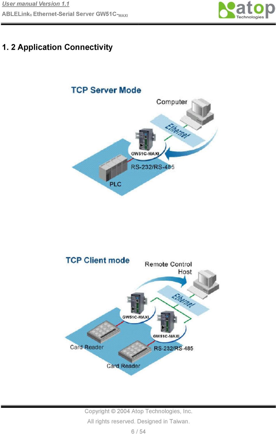
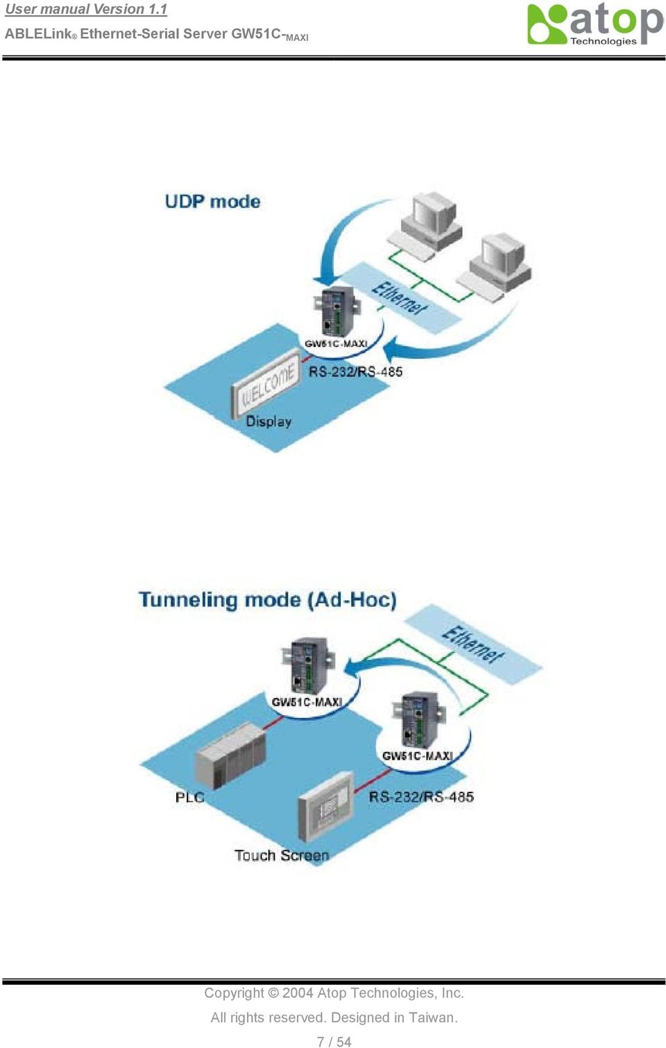
6 1. Introduction The Atop GW51C- MAXI Ethernet-Serial Server is a gateway between Ethernet (TCP/IP) and RS-232/RS-485 communications. The information transmitted by GW51C- MAXI is transparent to both host computers (Ethernet) and devices (RS-232/RS-485). Data coming from the Ethernet (TCP/IP) is sent to the designated RS-232/RS-485 port and data being received from RS-232/RS-485 port is sent to the Ethernet (TCP/IP) transparently. In the computer integration manufacturing or industrial automation area, the Atop GW51C- MAXI Ethernet-Serial Server is used for field devices to direct connect to Ethernet network. Terminal Server (main control program run in GW51C- MAXI ) transforms whatever data received from RS-232/RS-485 to TCP/UDP port then connect devices to the Ethernet network via a single application program or multiple application programs. Many control devices provide the ability to communicate with hosts through RS-232/RS-485 however RS-232/RS-485 serial communication has its limitations. For one, it is hard to transfer data through a long distance. With Atop GW51C- MAXI, it is possible to communicate with a remote device in the Intranet environment or even in the Internet and thus, increases the communication distance dramatically. GW51C- MAXI from Atop Technologies Inc. offers one RS-232/ RS-485 port, one RJ45 Ethernet and Watch-Dog Timer etc. 1.1 Packaging Atop Ethernet-Serial Server x 1 Atop Ethernet-Serial Server quick start guide x 1 Mini DIN to RS-232 DB-9 Cable x 1 Wall mount x 2 Product CD containing configuration utility and sample programs x 1 5 / 54

7 1. 2 Application Connectivity 6 / 54
8 7 / 54
9 2. Nomenclature and Settings 2.1 Nomenclature of GW51C- MAXI Components Figure 2.1 shows the names of GW51C- MAXI components. In the figure, the indicated switch settings represent factory settings. LED Indicator Mode Switch Mini-Din Pin Assignment Mode Switch Table Serial Port Mini D Connector Serial Port Terminal Block Connector UTP Connector Power Supply Inpu Connector Figure 2.1. Nomenclature of GW51C- MAXI components. 2.2 MODE Switch This sets or initializes the operating mode for the GW51C- MAXI. The factory default setting is that Switch 1 (SW1) and Switch 2 (SW2) are set to OFF. You can use the Mode switch to change the operating mode from the factory default settings to your desired mode. GW51C- MAXI can be setup either RS-232, RS-485, RS-422 or Console configuration mode by MODE Switch. SW1 SW2 Mode OFF ON OFF ON OFF ON 8 / 54 RS-232 CONSOLE RS-485 RS-422
 and Switch 2 (SW2) are set to OFF. You can use the Mode switch to change the operating mode from the factory default settings to your desired mode.")
10 3. Hardware Installation Prepare necessary cables, hub, power cord and RS232/RS485 connector. Connect GW51C- MAXI to Ethernet network via hub/switch or direct connect to host computer through cross over cable. Connect a serial device to a serial port of GW51C- MAXI, make sure the right connection of either RS-232 or RS-485. Plug in DC9-30V, the buzzer will beep and the RUN LED will blink if GW51C- MAXI functions normally. Please refer to Appendix A.4 to see all of LED messages. Use monitor.exe configuration utility in the product CD or diskette to diagnose GW51C- MAXI. If it starts up successfully, you are able to find the IP and MAC addresses of GW51C- MAXI. You can change the network parameters of GW51C- MAXI to join your LAN by changing its IP address, gateway IP address and subnet mask. 3.1 Configuration Atop GW51C- MAXI Ethernet-Serial Server is shipped with default settings shown in the following table: Property Default Value IP Address Gateway Subnet Mask User Name Password COM 1 Link 1 SysName of SNMP SysLocation of SNMP SysContact of SNMP admin Null 9600,None, 8, 1, No flow control, buffer disabled, packet delimiter timer 2ms Type: TCP Server, Listen port 4660, Filter= , Virtual COM disabled name location contact Note: Atop provides a default button to restore system settings including IP address, gateway IP address and subnet mask etc. to the defaults. Press and hold the default button for 5 seconds till the server reboots. 3.2 Assigning a new IP Address by ARP command ARP s is used to assign a static IP address of GW51C- MAXI and add this static entries to the ARP cache of the computer, when TCP/IP packet with destination port number 1 is sent to GW51C- MAXI, it causes the device to check its MAC address with IP address, once GW51C- MAXI finds those two unmatched, it will reboot and change to the new IP address which was set by ARP s command. The following example uses ARP to assign a static IP address of GW51C- MAXI using its MAC address printed on the label of the 9 / 54

11 rear panel, then use Telnet to send the TCP/IP packet with destination port number 1 to GW51C- MAXI, after GW51C- MAXI reboots it will change its IP address to the new one. Notes: 1. Arp command can only be used to set a static IP address of GW51C- MAXI using system default user name admin and default password null. 2. Only TCP/IP packet with destination port number 1 will lead GW51C- MAXI to reboot and change the IP address. 3.3 Auto IP A DHCP server automatically assigns the IP address and network settings. GW51C- MAXI supports DHCP. It will supply for the unit with an IP address gateway address, and subnet mask. You may use Monitor.exe software to search network information automatically by putting a check on Auto IP on Dialog window. 10 / 54

12 3.4 TCP/IP Port Number Port number 4660 is default of GW51C- MAXI and is associated with serial port COM1 respectively. After your application program connects to the TCP port 4660 of GW51C- MAXI, data being sent to this TCP connection from your application program are transparent to the COM1 of GW51C- MAXI. Vice versa is also true. 11 / 54

13 4. Software Configuration 4.1 Configuration set by monitor.exe utility Use monitor.exe that comes with the product CD or diskette to configure the network parameters of GW51C- MAXI. As you can see from the following picture, you can change IP address, gateway IP address, subnet mask, user ID and password of GW51C- MAXI from the utility. For more details of the utility please refer to Appendix-D Configuration Utility. 4.2 Configuration set by Telnet utility You can use Telnet utility to change configuration settings of GW51C- MAXI. To do so, please do the following. Log in to the system Telnet to 51C- MAXI using command Telnet IP_address. For example Telnet After telnet to GW51C- MAXI, system prompts for a password, the default password is null. Note: You can press the default button of GW51C- MAXI to reset the password to the default value. 2. After verifying the password, the following terminal screen appears. 12 / 54

14 + NOTE: 1. If GW51C- MAXI does not receive any command within 1 minute, Telnet will be terminated automatically. 2. The changes of networking parameters will take effect only when you exit and restart GW51C- MAXI. 3. Select 1 from Input choice and enter (0~4): to enter overview page as following: This page gives you the general information of GW51C- MAXI including IP and MAC address, SNMP information, kernel and AP version, and connection status of the device. Networking Select 2 from Input choice and enter (0~4): to enter Networking page as following: 13 / 54

15 This page allows you to change network settings of the device including IP address, subnet mask, gateway IP address and SNMP information of GW51C- MAXI. Please notice that any setting change made on this page won t take effect until you restart the device. Change the password 1. Select 3 from Input choice and enter (0~4): the following screen appears. 2. If you want to change the password, please type the old password in the Please input old password field, type the new password in the Please input new password and the Please verify new password fields. 14 / 54

16 Note: You can press the default key of product to reset password to the default value. COM1 Setup Select 4 from Input choice and enter (0~4): the following screen appears: The page gives you the opportunity to configure parameters of COM1 setting which include COM1 working mode, port parameters, enabling or disabling serial buffer s data and setting packet delimiter. LINK1 Setup Type 1 from Input choice and enter (1~4): of COM1, the following screen appears. Configure GW51C- MAXI as TCP server and the local port is IP filter is disabled by default, if IP filter is enabled, only source IP can connect to GW51C- MAXI. Note: IP filtering function is disabled if setting FILTER_IP to / 54
: of COM1, the following screen appears. Configure GW51C- MAXI as TCP server and the local port is 4660.")
17 Configure GW51C- MAXI as TCP client, the destination IP is , destination port is / 54

18 Configure GW51C- MAXI as UDP client, the local port is 4660, the destination IP is , destination port is / 54

19 COM port setting Type 2 from Input choice and enter (1~4): of COM1, the following screen appears, you can then give the COM port alias name, set the baud rate and parity, determine number of data bit and stop bit, and decide if you want to use flow control and the type of flow control you want to use. 18 / 54

20 Enabling serial data buffer Type 3 from Input choice and enter (1~4): of COM1, by default COM port serial data buffer is enabled meaning that when TCP/IP Ethernet connection is broken, serial data collected from serial device will be kept in GW51C- MAXI, once TCP/IP connection is resumed, the serial data will be sent through Ethernet connection, you can disable it if you wish. 19 / 54

21 Setting packet delimiter Packet delimiter is a way of controlling packets within serial communication. It can prevent packets from being cut thus keep the packets complete. GW51C- MAXI provides two ways of parameter setting as inter character timer and terminator. By default packet delimiter timer is 1 ms, you can change timer shown in the following figure: 20 / 54
22 You can also choose character pattern as the packet delimiter indicated in the following figure: 21 / 54
23 4.3 Configuration set by Hyper Terminal console utility 1. Power off GW51C- MAXI. 2. Set the MODE switch SW1 to OFF and SW2 to ON. 3. Use a PC to connect to GW51C- MAXI s console with RS-232 cross over cable. 4. Power on GW51C- MAXI. 5. Open a Hyper Terminal program from your computer Start menu -> Programs -> Accessories -> Communication -> Hyper Terminal, set COM2 parameters as follows. - Baud rate: 9600 bps - Data bit: 8 bits - Parity: None - Stop bit: 1bit - Flow control: None Note: At present time baud rate is fixed at 9600, 8, n, 1, without flow control for console port communication, RS-232C parameters of your computer COM port and GW51C- MAXI must be the 22 / 54
24 same. 6. Once Hyper Terminal is connected, type in username and password then the following Hyper Terminal window appears, 7. The following configuration operations are totally the same as those by Telnet. 8. After finishing console settings, power off GW51C- MAXI, put SW1 and SW2 back to the previous setting. 4.4 Configuration set by web browser It is also possible to modify various settings through the web server interface. To do so, please follow the steps below. Log in to the system 1. From web browser, type in the IP address of GW51C- MAXI in the URL. Example: 2. The following authentication screen appears. Please type in user name and password then click on OK. The user name is admin and password is null by default. 23 / 54
25 3. The following overview page appears. Change the password 1. Click on the Security link and the following screen appears. 24 / 54
26 2. Please input the old password in the Old Password field, input the new password in the New Password and the Verified Password fields, and then click on Save Configuration to update the password. Note: You can press the default key of product to reset password to the default value. Network setup Click on the Networking link and the following screen appears. Fill in IP information under TCP/IP field. Alternatively, you can do the configuration by clicking on DHCP to obtain auto IP address, gateway and subnet mask information. Enable SNMP by checking Enable, fill in network identification information under SNMP field and click on the Save Configuration button to save the changes, please notice that the setting will not become effective until you restart GW51C- MAXI. 25 / 54
27 COM1 Setup 1. Click on the COM1 link and the following screen appears. Fill in COM1 parameter information under COM1 field then click on Save Configuration button to save the changes. 26 / 54
28 LINK1 Setup 1. Click on the COM1 link and the following screen appears, you can configure GW51C- MAXI as transparent mode by default. Configure GW51C- MAXI as TCP server and the local port is 4660, IP filter is disabled by default, if IP filter is enabled, only source IP can connect to GW51C- MAXI. Configure GW51C- MAXI as TCP client, the destination IP is , destination port is Pair Connection In the case of the serial connection is established with two or more GW51C- MAXI to send data over Ethernet network, i.e. pair connection mode, you can choose pair connection which is indicated in the following figure to cope with any type of serial device. 27 / 54
29 Configure GW51C- MAXI as UDP mode. Local port is 4660, destination IP is and destination port is Click on Save Configuration to save the changes. 3. If the update is successful, the following screen appears. 28 / 54
30 4.5 Virtual COM Mode Virtual COM driver mode for windows converts COM data to LAN data to control the RS-232C port on a GW51C- MAXI via the LAN. By creating virtual COM ports on the PC, Atop Virtual COM redirects the communications from the virtual COM ports to an IP address and port number on a GW51C- MAXI that connects the serial line device to the network. The following figure is Atop Virtual COM connection diagram. PC HUB Serial Line Serial Device 1 Serial Line Physical COM1 Serial Device 2 Physical COM2 COM3 (Virtual COM Port) COM4 (Virtual COM Port) COM5 (Virtual COM Port) COM6 (Virtual COM Port) TCP/IP Network Serial Line Serial Line Serial Device 3 Serial Device 4 OS Driver Level : : COM256 (Virtual COM Port) GW51C-MAXI Setup of a virtual COM driver Pre-installation requirements Please check the operation system on your PC complied with the following requirements: Processor: Intel-compatible, Pentium class Operation system: Windows Server 2003, Windows XP, Windows 2000, Windows NT 4.0 SP5 or later, Windows Me, Windows 98, Windows 95, Microsoft NT/2000 Terminal Server, Citrix MetaFrame Windows Installer 2.0 Network: Microsoft TCP/IP networking software 29 / 54
31 Applying to the serial server Cautions on Use Atop Virtual COM supports firmware AP v3.4 and above of ABLELink Serial-Ethernet Servers. Limitation Atop Virtual COM driver provides user to select up to 256 COM ports as Virtual COM ports in a monitoring PC. User can select them from a list of COM ports, which is from COM1 up to COM256. Installation Make sure you have turned off all anti-virus software before beginning the installation. Run AtopVcom.exe program included in the CD to install Atop Virtual COM for your operating system. In the end of the installation, please select one or two COM ports to become the Virtual COM ports. Uninstalling 1. From Windows Start menu select Setting, Control Panel, Add/Remove Programs. 2. Select Serial IP for ATOP in the list of installed software. 3. Click the Add/Remove button to remove the program, or From Windows Start menu select Programs, Serial IP for ATOP, Uninstall Serial IP for ATOP to remove the program Virtual COM communication Enable Virtual COM on GW51C- MAXI From web browser access to GW51C- MAXI by typing its IP address, click on COM1 link to access COM1 page, on the top half of the page click on TCP Server and enable Virtual COM by putting a check in front of the Enable button, then type in the local port number in the Local Port field as indicated in the following figure: 30 / 54
32 For the users of Mitsubishi A-Series PLC, it may be recommended to enable Mitsubishi A-Series PLC in the case of some connection problems occurred. Or you can enable Virtual COM through telnet configuration by setting COM1 as TCP server, and type in the local port number for COM1, then enable virtual COM as shown in the following figure: 31 / 54
33 Run Serial/IP for ATOP program on monitoring PC In the Window Start Menu, select the Serial/IP for ATOP program group and select Serial/IP for ATOP Configuration. The configuration window is shown as following: 32 / 54
34 At right is a sample Virtual COM Control Panel window. At the left is the list of the COM ports that you have selected (in the Select Ports window) for use by the Virtual COM Redirector. If you wish to change which ports appear in this list, use the Select Ports button. Each COM port has its own settings. When you click on a COM port, the Control Panel display changes to reflect the settings for that COM port. Note: When you change settings for a COM port, the changes are effective immediately. There is no separate confirmation dialog to confirm or cancel your changes. Configuring Virtual COM Ports You configure each Serial/IP COM port as follows: 1. Select a COM port in the list. 2. For IP Address of Server, enter a numeric IP address for the serial server. 3. For Port Number, enter the TCP port number that the serial server uses to provide its serial ports to the network. 4. For Server Credentials, the default is No Login Required. If your serial server does require a login by the Virtual COM Redirector, the Virtual COM Redirector needs to provide a username 33 / 54
35 and/or password every time an application tries to use the serial server. 5. Click the Configuration Wizard button and then click the Start button that appears in the wizard window. This important step verifies that the Virtual COM Redirector can communicate with the serial server using the settings you have provided. If the Log display does not show errors, click the Use Settings button in the wizard, which makes the recommended settings effective and returns you to the Control Panel to continue with the following steps. 6. For Connection Protocol, the setting must match the TCP/IP protocol that the serial server supports. The Configuration Wizard is usually able to determine the correct setting. 7. For COM Port Options, the settings must match the COM port behavior expected by the PC application that will use this COM port. The Configuration Wizard will recommend a combination of settings. 34 / 54
36 5. SNMP Setup 5.1 SNMP Network Management Platform Atop GW51C- MAXI is an SNMP device that allows many popular SNMP Network management platforms such as HP OpenView and SunNet Manager to conduct monitoring on the device. Depending on the network management tools you are using, device (GW51C- MAXI ) information can be collected from running the management tools including IP address, DNS name, system descriptions and NIC information etc. 5.2 Using NetworkView As An Example The NetworkView is a compact network management tool from NetworkView Software, Inc. ( It discovers all TCP/IP nodes in a network using DNS, SNMP and ports information and documents with printed maps and reports for future use. You may visit their web sites and get a free download. To use NetworkView, you will need to download and install the tool on your PC (Windows NT and Windows 9x only). Please refer to the installation instructions that come with the tool. 1. After you have done the NetworkView installation, start NetworkView. 2. Click on the button to open a new file. The following screen appears, in the Addresses field, type in the IP address range to search. 35 / 54
37 3. Click on OK and the following dialog box appears. It displays the searching progress. 4. When the search is completed, NetworkView will display the devices found in the main window, as shown in the following diagram. 5. Double-click on the device icon to display information about the device, including IP Address, Company, SysLocation (Max 15 characters), SysName (Max 9 characters) and types etc. Note: 1. The NetworkView tool is limited to information extracting and viewing only. 2. To modify the configurations please use the web server, Telnet or monitor.exe configuration utilities. 36 / 54
38 6. Start Writing Your Own Applications Before you start writing your host applications or programs to interact with GW51C- MAXI, please make sure you have done the following. 6.1 Preparing The System 1. Properly connect GW51C- MAXI hardware including power, Ethernet and RS-232/RS-485 cables. 2. Properly configure the parameters of GW51C- MAXI including connection type, IP address, gateway IP address, and network mask accordingly (see chapter 3 Hardware Installation section). 3. Configure GW51C- MAXI as TCP Server using default TCP port number The host (PC) application program must be configured as a TCP client and connects to GW51C- MAXI with designated TCP port number 4660 for COM1. 5. Make sure GW51C- MAXI is running by checking the running status through monitor.exe configuration utility. 6.2 Running The Sample Program Sample programs written in VB and VC++ included in package are provided for your reference, source codes are also included. Test program can be found in the product CD or diskette under the directory of \sample\vb_ap\ and \sample\vc_ap respectively. There are two test programs, TCPTEST written in Visual Basic and TCPTEST2 written in Visual C TCPTEST in Visual Basic This sample program is written in Visual Basic 5.0 with Winsock Controls. It shows you how to send and receive data between host (PC) and GW51C- MAXI via Ethernet in two socket ports. Run Visual Basic and open sample program tcptest.vbp, after the program is started successfully, you can start testing functions. For more information, please press Help in the program to get detail explanation. Note: Please be sure the Microsoft visual studio family software is installed on the computer. Otherwise the sample program will not run. 37 / 54
39 Status Status TCPTEST2 in Visual C To start the program, please type in the following command in the command line prompt: TCPTEST2 IP_Address Port_Number 38 / 54
40 The command tcptest brings you to connect to a TCP server of IP address and port number 4660, the received data is displayed on the screen and the data typed in is sent to the TCP server of the designated port number. You can also send binary data in hex format with a leading character \. For example, \00 and \FF represent ASCII code 0 and 255 respectively. You can also use modem to connect to the serial server. Command "AT\Od" sends standard AT command to the modem which in return responds with "OK\0D\0A" message to the host application. Always use '=' then Enter key to exit the program. 39 / 54
41 7. Diagnostics There are several ways you can check on the status and availability of GW51C- MAXI. 7.1 Use Standard TCP/IP Utility ping Command From Windows Start menu, select Run and type in ping <TCP Server IP address>. If the connection is established, the Reply messages are displayed, otherwise it will indicate Request timed out. 7.2 Use monitor.exe Configuration Utility Program Use monitor.exe configuration program that comes with the product CD or diskette to check on the status of GW51C- MAXI. The status can be read from AP version column of the tool. Status S C U A B Descriptions The system is configured as a TCP Server and not yet connected. The system is configured as a TCP Client and not yet connected. The system is configured as an UDP. The TCP Server and is connected. The TCP Client and is connected. 40 / 54
42 For example, s means that COM1 is server mode and is not connected. 7.3 Use TCPTEST.EXE or TCPTEST2.EXE Sample Program Use sample programs TCPTEST.EXE and TCPTEST2.EXE that comes with the product CD or diskette to check on the status of GW51C- MAXI. Please refer to chapter 6.2 to run the sample programs. 41 / 54
43 Appendix A: GW51C- MAXI Ethernet-Serial Server Specifications A.1. Hardware Specifications CPU 16-bit Embedded CPU 100MHz Flash Memory 512K Bytes SDRAM 512K Bytes EEPROM 512 Bytes Host Communication IEEE802.3 base band Specifications TCP/IP, UDP, SNMP, HTTP, Telnet, ARP, BOOTP, DHCP Reset Built-in default key to restore factory default settings Watch Dog Timer 1.34 second hardware auto reset Serial Port Communication Power failure threshold: 4.75V One RS-232 or RS-485 selectable RS-232: EIA-RS-232C standard, Full Duplex, 8 pins Mini-DIN or 5 pins terminal block RS-485: 2/4 wires, Half/Full duplex, 8 pins Mini-DIN or 5 pins terminal Parameters LED indication RUN x 1 LAN x 1 COM port1 1) Baud-rate: 1200 bps ~ bps 2) Parity: None, Even, Odd, Mark, Space 3) Data bits: 7,8 4) Stop bits: 1,2 Power Requirement +9~30Vdc, 2.8 Watt Max Temperature Operation: Storage: 5) Packet Delimiter: by inter-character timeout, by characters delim 6) Flow Control: None, Hardware CTS/RTS, Software Xon/Xoff 0 to to 70 Humidity 20%~90% non-condensing Housing 91mm(L) x 46mm(W) x 76mm(H) 42 / 54
44 A.2. Software Specifications Protocol Item Specifications TCP, UDP, ARP, ICMP, SNMP, HTTP, Telnet, BOOTP,DHCP Configuration Configuration information for both TCP/IP and serial ports is kept in the EEPROM. Configuration utilities of Windows 95/98/2000/NT/XP/2003 are provided for configuring settings. Internal Buffer Size TCP receiving buffer size = 8K bytes TCP transmitting buffer size = 16K bytes RS-232/RS-485 receiving buffer size = 4K bytes RS-232/RS-485 transmitting buffer size = 4K bytes A.3 Connector Pin Assignments A.3.1 COM Port 8 pin Mini DIN connector 43 / 54
45 Pin assignments of Mini DIN connector is shown in the following table: Pin# RS-232 Full Duplex RS wire, Half Duplex RS wire, Full Duplex 1 DCD N/A N/A 2 RXD N/A RxD/T+ 3 TXD TxD/R+ TxD/R+ 4 DTR N/A (reserved) N/A 5 SG (Signal Ground) SG (Signal Ground) SG (Signal Ground) 6 DSR N/A N/A 7 RTS RTS/R- RTS/R- 8 CTS N/A CTS/T- 9 N/A N/A (reserved for Atop devices) N/A Atop provides Mini DIN connector to DB9 connector cable, the pin assignments of DB9 connector is shown in the following table: Pin# RS-232 Full Duplex RS wire, Half Duplex 1 DCD N/A N/A 2 RXD N/A N/A 3 TXD DATA- RXD- 4 DTR N/A (reserved) TXD- RS wire, Full Duplex 5 SG (Signal Ground) SG (Signal Ground) SG (Signal Ground) 6 DSR N/A N/A 7 RTS N/A N/A 8 CTS DATA+ RXD+ 9 RI N/A (reserved for Atop devices) TXD+ Note: RS485 2 or 4 pins assignments of DB9 connector are different from those of Mini DIN connector. 44 / 54
Serial-Ethernet Server STE-501C. User s Manual
 Serial-Ethernet Server User s Manual Version 1.3 IMPORTANT ANNOUNCEMENT The information contained in this document is the property of Aaxeon Technologies, LLC and is supplied for the sole purpose of the
User s Manual. 2-Port Ethernet Serial Server
 User s Manual Atop ABLELink SE5002 Series 2-Port Ethernet Serial Server Version 1.2 Updated on 2007/03/15 Tel: 886-3-5508137 Fax: 886-3-5508131 www.atop.com.tw IMPORTANT ANNOUNCEMENT The information contained
Atop Technologies, Inc. 1-port Modbus Gateway MB5001C/MB5001C-Sis
 Atop Technologies, Inc. 1-port Modbus Gateway MB5001C/MB5001C-Sis User s Manual Version 1.0 Updated on 2010/07/28 Tel: 886-3-5508137 Fax: 886-3-5508131 http://www.atop.com.tw Important Announcement The
User s Manual TCP/IP TO RS-232/422/485 CONVERTER. 1.1 Introduction. 1.2 Main features. Dynamic DNS
 MODEL ATC-2000 TCP/IP TO RS-232/422/485 CONVERTER User s Manual 1.1 Introduction The ATC-2000 is a RS232/RS485 to TCP/IP converter integrated with a robust system and network management features designed
One Port Serial Server Users Manual Model ESP901, ESP901E
 One Port Serial Server Users Manual Model ESP901, ESP901E Documentation Number: ESP901-2303 International Headquarters B&B Electronics Mfg. Co. Inc. 707 Dayton Road -- P.O. Box 1040 -- Ottawa, IL 61350
3.1 RS-232/422/485 Pinout:PORT1-4(RJ-45) RJ-45 RS-232 RS-422 RS-485 PIN1 TXD PIN2 RXD PIN3 GND PIN4 PIN5 T+ 485+ PIN6 T- 485- PIN7 R+ PIN8 R-
 RJ-45 RS-232 RS-422 RS-485 PIN1 TXD PIN2 RXD PIN3 GND PIN4 PIN5 T+ 485+ PIN6 T- 485- PIN7 R+ PIN8 R-") MODEL ATC-2004 TCP/IP TO RS-232/422/485 CONVERTER User s Manual 1.1 Introduction The ATC-2004 is a 4 Port RS232/RS485 to TCP/IP converter integrated with a robust system and network management features
MODEL ATC-2004 TCP/IP TO RS-232/422/485 CONVERTER User s Manual 1.1 Introduction The ATC-2004 is a 4 Port RS232/RS485 to TCP/IP converter integrated with a robust system and network management features
IP SERIAL DEVICE SERVER
 IP SERIAL DEVICE SERVER ( 1 / 2 / 4 serial port ) Installation guide And User manual Version 1.0 1Introduction... 5 1.1Direct IP mode...5 1.2Virtual COM mode...5 1.3Paired mode...6 1.4Heart beat... 6
1 Serial RS232 to Ethernet Adapter Installation Guide
 Installation Guide 10/100 Mbps LED (amber color ) Link/Activity LED (green color ) 1. Introduction Thank you for purchasing this 1-port RS232 to Ethernet Adapter (hereinafter referred to as Adapter ).
MODBUS TCP to RTU/ASCII Gateway. User s Manual
 MODBUS TCP to RTU/ASCII Gateway User s Manual 1 INTRODUCTION... 1 1.1 FEATURES... 2 1.2 PRODUCT SPECIFICATIONS... 3 1.3 DEFAULT SETTINGS... 4 2 MAKING THE HARDWARE CONNECTIONS... 5 2.1 POWER CONNECTION...
TCP/IP Converter DDS EX-9132 Operation Manual for 8051 Series
 TCP/IP Converter DDS EX-9132 Operation Manual for 8051 Series First Edition, March 2005 Table of Contents 1. Introduction 3 Overview 4 Package Checklist 5 Block Diagram 6 Features 7 Product Specifications
TDP43ME NetPS. Network Printer Server. Control Center. for Ethernet Module
 Panduit Corp. 2010 TDP43ME NetPS PA26306A01 Rev. 01 11-2010 Network Printer Server Control Center for Ethernet Module NOTE: In the interest of higher quality and value, Panduit products are continually
Broadband Router ESG-103. User s Guide
 Broadband Router ESG-103 User s Guide FCC Warning This equipment has been tested and found to comply with the limits for Class A & Class B digital device, pursuant to Part 15 of the FCC rules. These limits
Vantage RADIUS 50. Quick Start Guide Version 1.0 3/2005
 Vantage RADIUS 50 Quick Start Guide Version 1.0 3/2005 1 Introducing Vantage RADIUS 50 The Vantage RADIUS (Remote Authentication Dial-In User Service) 50 (referred to in this guide as Vantage RADIUS)
BIT COMMANDER. Serial RS232 / RS485 to Ethernet Converter
 BIT COMMANDER Serial RS232 / RS485 to Ethernet Converter (Part US2000A) Copyrights U.S. Converters 1 Contents Overview and Features... 3 Functions..5 TCP Server Mode... 5 Httpd Client Mode.5 TCP Auto mode....6
LAN / WAN Connection Of Instruments with Serial Interface By Using a Terminal Server
 Products: EFA with EFA Scan, DVRM and DVMD with Realtime Monitor or Stream Explorer DVMD-B1 LAN / WAN Connection Of Instruments with Serial Interface By Using a Terminal Server Remote control of test and
User Manual. PePWave Surf / Surf AP Indoor Series: Surf 200, E200, AP 200, AP 400. PePWave Mesh Connector Indoor Series: MC 200, E200, 400
 User Manual PePWave Surf / Surf AP Indoor Series: Surf 200, E200, AP 200, AP 400 PePWave Mesh Connector Indoor Series: MC 200, E200, 400 PePWave Surf AP Series: Surf AP 200-X, E200-X, 400-X PePWave Surf
ABLELink. EW5302 Ethernet to Wireless Client Adaptor. User s Manual
 ABLELink EW5302 Ethernet to Wireless Client Adaptor User s Manual Version 1.0 Updated on November 13, 2008 TEL: 886-3-5508137 FAX: 886-3-5508131 http://www.atop.com.tw Important Announcement The information
Prestige 314 Read Me First
 Prestige 314 Read Me First Console WAN 10M PORT Prestige Rear Panel Connections CONNECTION Use an RS-232 console cable. Use the cable that came with your broadband modem. LAN 10/100M Port Number COMPUTER
Prestige 324. Prestige 324. Intelligent Broadband Sharing Gateway. Version 3.60 January 2003 Quick Start Guide
 Prestige 324 Intelligent Broadband Sharing Gateway Version 3.60 January 2003 Quick Start Guide 1 Introducing the Prestige The Prestige is a broadband sharing gateway with a built-in four-port 10/100 Mbps
Prestige 650R-31/33 Read Me First
 Prestige 650R-31/33 Read Me First Prestige Rear Panel Connections PORT DSL CONSOLE LAN 10/100M POWER Connect to a telephone jack using a telephone wire. CONNECTION Connect to a serial port (COM port) on
LBNP16312. RS-232/485/422 serial device server. User manual
 Tu Sitio de Automatización! LBNP16312 RS-232/485/422 serial device server User manual Summarize-----------------------------------------------------------------------------14-3 Package checklist---------------------------------------------------------------------14-3
Serial over Ethernet Device Server. User s Manual
 Serial over Ethernet Device Server User s Manual Second Edition, November 2005 SUNIX Co., Ltd. Tel : +886-2-8913-1987 Fax: +886-2-8913-1986 Http://www.sunix.com.tw info@sunix.com.tw Serial over Ethernet
Prestige 324 Quick Start Guide. Prestige 324. Intelligent Broadband Sharing Gateway. Version V3.61(JF.0) May 2004 Quick Start Guide
 May 2004 Quick Start Guide") Prestige 324 Intelligent Broadband Sharing Gateway Version V3.61(JF.0) May 2004 Quick Start Guide 1 1 Introducing the Prestige The Prestige is a broadband sharing gateway with a built-in four-port 10/100
Prestige 324 Intelligent Broadband Sharing Gateway Version V3.61(JF.0) May 2004 Quick Start Guide 1 1 Introducing the Prestige The Prestige is a broadband sharing gateway with a built-in four-port 10/100
Connecting the DG-102S VoIP Gateway to your network
 Contents of Package: DG-102S VoIP Station Gateway Power adapter CD-ROM, including User s Manual Quick Install Guide Requirements: RS-232 Console Cable Two RJ-45 CAT-5 Straight-Through Cables For more information
Ethernet Radio Configuration Guide
 Ethernet Radio Configuration Guide for Gateway, Endpoint, and Repeater Radio Units April 20, 2015 Customer Service 1-866-294-5847 Baseline Inc. www.baselinesystems.com Phone 208-323-1634 FAX 208-323-1834
Prestige 623R-T. Quick Start Guide. ADSL Dual-link Router. Version 3.40
 Prestige 623R-T ADSL Dual-link Router Quick Start Guide Version 3.40 February 2004 Introducing the Prestige The Prestige 623R-T ADSL Dual-link Router is the ideal all-in-one device for small networks connecting
GV-Data Capture V3 Series User's Manual
 GV-Data Capture V3 Series User's Manual Before attempting to connect or operate this product, please read these instructions carefully and save this manual for future use. 2006 GeoVision, Inc. All rights
Chapter 6 Using Network Monitoring Tools
 Chapter 6 Using Network Monitoring Tools This chapter describes how to use the maintenance features of your Wireless-G Router Model WGR614v9. You can access these features by selecting the items under
User Manual Revision 1.400 English Converter / Adapter Ethernet to RS232 / RS485 (Order Code: HD67038-2 HD67038-2-M HD67038-25 HD67038-25-M)
") Document code: MN67038-2_ENG Revision 1.400 Page 1 of 25 User Manual Revision 1.400 English Converter / Adapter Ethernet to RS232 / RS485 (Order Code: HD67038-2 HD67038-2-M HD67038-25 HD67038-25-M) for
Document code: MN67038-2_ENG Revision 1.400 Page 1 of 25 User Manual Revision 1.400 English Converter / Adapter Ethernet to RS232 / RS485 (Order Code: HD67038-2 HD67038-2-M HD67038-25 HD67038-25-M) for
Connecting and Setting Up Your Laptop Computer
 CHAPTER 3 Connecting and Setting Up Your Laptop Computer This chapter explains how to connect your laptop to the Cisco Unified MeetingPlace system and how to set up your laptop so that you can use HyperTerminal.
To perform Ethernet setup and communication verification, first perform RS232 setup and communication verification:
 PURPOSE Verify that communication is established for the following products programming option (488.2 compliant, SCPI only): DCS - M9C & DCS M130, DLM M9E & DLM-M9G & DLM M130, DHP - M9D, P series, SG,
Setup Manual and Programming Reference. RGA Ethernet Adapter. Stanford Research Systems. Revision 1.05 (11/2010)
") Setup Manual and Programming Reference Stanford Research Systems Revision 1.05 (11/2010) Certification Stanford Research Systems certifies that this product met its published specifications at the time
Setup Manual and Programming Reference Stanford Research Systems Revision 1.05 (11/2010) Certification Stanford Research Systems certifies that this product met its published specifications at the time
RS-232/422/485 to 10/100Base-TX Device Server / Managed Media Converter (IRF-633) User s Manual
 User s Manual") RS-232/422/485 to 10/100Base-TX Device Server / Managed Media Converter (IRF-633) User s Manual COPYRIGHT All rights reserved. No part of this publication may be reproduced, stored in a retrieval system,
RS-232/422/485 to 10/100Base-TX Device Server / Managed Media Converter (IRF-633) User s Manual COPYRIGHT All rights reserved. No part of this publication may be reproduced, stored in a retrieval system,
TRP-C31M MODBUS TCP to RTU/ASCII Gateway
 TRP-C31M MODBUS TCP to RTU/ASCII Gateway User s Manual Printed Feb. 2007 Rev 1.0 Trycom Technology Co., Ltd 1F, No.2-11, Sihu street, Yingge Township, Taipei, Taiwan ROC Tel: 886-2-86781191, Fax: 886-2-86781172
Serial Over IP Ethernet Device Server
 NETRS2321E NETRS2321EEU NETRS2321EGB Instruction Manual Serial Over IP Ethernet Device Server 1 Port RS-232/422/485 Serial over IP Ethernet Device Server Manual Revision:10/13/2010 For the most up-to-date
USER MANUAL. PingBrother EPIW104 managed passive poe switch & IP watchdog
 USER MANUAL PingBrother EPIW104 managed passive poe switch & IP watchdog CONTENT Content... 2 Chapter 1... 3 1.1 Preface... 3 1.2 CE mark warning... 3 1.3 FCC warning... 4 Chapter 2... 5 2.1 Physical description...
Legal Disclaimers. For C-UL Listed applications, the unit shall be installed in accordance with Part 1 of the Canadian Electrical Code.
 ACS5000 Networking Admin Interface Guide 1/21/2015 Legal Disclaimers Federal Communications Commission (FCC) Compliancy This equipment has been tested and found to comply with the limits for a Class B
50-Port 10/100/1000Mbps with 4 Shared SFP. Managed Gigabit Switch WGSW-50040. Quick Installation Guide
 50-Port 10/100/1000Mbps with 4 Shared SFP Managed Gigabit Switch WGSW-50040 Quick Installation Guide Table of Contents 1. Package Content... 3 2. Switch Management... 4 3. Requirements... 5 4. Terminal
Wireless Router Setup Manual
 Wireless Router Setup Manual NETGEAR, Inc. 4500 Great America Parkway Santa Clara, CA 95054 USA 208-10082-02 2006-04 2006 by NETGEAR, Inc. All rights reserved. Trademarks NETGEAR is a trademark of Netgear,
BiPAC 7404V series. VoIP/(802.11g) ADSL2+ (VPN) Firewall Router. Quick Start Guide
 ADSL2+ (VPN) Firewall Router. Quick Start Guide") BiPAC 7404V series VoIP/(802.11g) ADSL2+ (VPN) Firewall Router Quick Start Guide VoIP/(802.11g) ADSL2+ (VPN) Firewall Router For more detailed instructions on configuring and using the Billion VoIP/(802.11g)
BiPAC 7404V series VoIP/(802.11g) ADSL2+ (VPN) Firewall Router Quick Start Guide VoIP/(802.11g) ADSL2+ (VPN) Firewall Router For more detailed instructions on configuring and using the Billion VoIP/(802.11g)
PePWave Surf Series PePWave Surf Indoor Series: Surf 200, AP 200, AP 400
 PePWave Surf Series PePWave Surf Indoor Series: Surf 200, AP 200, AP 400 PePWave Surf Outdoor Series: Surf AP 200/400-X, PolePoint 400-X, Surf 400-DX User Manual Document Rev. 1.2 July 07 COPYRIGHT & TRADEMARKS
RS-232/422/485, Power over Ethernet
 IP-COM-M IP-COMi-M IP-COM-M PoE IP-COMi-M PoE RS-232 RS-232/422/485 RS-232, Power over Ethernet RS-232/422/485, Power over Ethernet Edition: September 2012 The computer programs provided with the hardware
Chapter 6 Using Network Monitoring Tools
 Chapter 6 Using Network Monitoring Tools This chapter describes how to use the maintenance features of your RangeMax Wireless-N Gigabit Router WNR3500. You can access these features by selecting the items
PREFACE http://www.okiprintingsolutions.com 07108001 iss.01 -
 Network Guide PREFACE Every effort has been made to ensure that the information in this document is complete, accurate, and up-to-date. The manufacturer assumes no responsibility for the results of errors
TCP/IP MODULE CA-ETHR-A INSTALLATION MANUAL
 TCP/IP MODULE CA-ETHR-A INSTALLATION MANUAL w w w. c d v g r o u p. c o m CA-ETHR-A: TCP/IP Module Installation Manual Page Table of Contents Introduction...5 Hardware Components... 6 Technical Specifications...
xpico User Guide Part Number 900-618 Revision A April 2012
 xpico User Guide Part Number 900-618 Revision A April 2012 Copyright and Trademark 2012 Lantronix. All rights reserved. No part of the contents of this book may be transmitted or reproduced in any form
Prestige 202H Plus. Quick Start Guide. ISDN Internet Access Router. Version 3.40 12/2004
 Prestige 202H Plus ISDN Internet Access Router Quick Start Guide Version 3.40 12/2004 Table of Contents 1 Introducing the Prestige...3 2 Hardware Installation...4 2.1 Rear Panel...4 2.2 The Front Panel
DSA-1000 / PRT-1000 Device Server / Thermal Printer
 LevelOne DSA-1000 / PRT-1000 Device Server / Thermal Printer User Manual V2.0 TABLE OF CONTENTS 1. INTRODUCTION...- 3-2. DEVICE OVERVIEW...- 7-3. HARDWARE SETUP...- 10-4. SYSTEM CONFIGURATION...- 12 -,
RN-XV-RD2 Evaluation Board
 RN-XV-RD2 Evaluation Board 2012 Roving Networks. All rights reserved. -1.01Version 1.0 9/28/2012 USER MANUAL OVERVIEW This document describes the hardware and software setup for Roving Networks RN-XV-RD2
TL-PS310U Single USB 2.0 Port MFP and Storage Server
 TL-PS310U Single USB 2.0 Port MFP and Storage Server Rev: 2.0.0 1910010313 Contents Chapter 1 Introduction... 1 1.1 Product Overview...1 1.2 Network Management...1 1.3 Components and Features...1 1.4 Hardware
ENET-710. ENET-710 - Ethernet Module ENET-710 JAN / 06 FOUNDATION
 ENET-710 ENET-710 - Ethernet Module JAN / 06 ENET-710 FOUNDATION E N E T 7 1 0 ME smar www.smar.com Specifications and information are subject to change without notice. Up-to-date address information is
ZyWALL 5. Internet Security Appliance. Quick Start Guide Version 3.62 (XD.0) May 2004
 May 2004") ZyWALL 5 Internet Security Appliance Quick Start Guide Version 3.62 (XD.0) May 2004 Introducing the ZyWALL The ZyWALL 5 is the ideal secure gateway for all data passing between the Internet and the LAN.
ZyWALL 5 Internet Security Appliance Quick Start Guide Version 3.62 (XD.0) May 2004 Introducing the ZyWALL The ZyWALL 5 is the ideal secure gateway for all data passing between the Internet and the LAN.
SIP Proxy Server. Administrator Installation and Configuration Guide. V2.31b. 09SIPXM.SY2.31b.EN3
 SIP Proxy Server Administrator Installation and Configuration Guide V2.31b 09SIPXM.SY2.31b.EN3 DSG, DSG logo, InterPBX, InterServer, Blaze Series, VG5000, VG7000, IP590, IP580, IP500, IP510, InterConsole,
Application Note 2. Using the TCPDIAL & TCPPERM Commands to Connect Two TransPort router Serial Interfaces Over TCP/IP.
 Application Note 2 Using the TCPDIAL & TCPPERM Commands to Connect Two TransPort router Serial Interfaces Over TCP/IP. Reverse Telnet or Serial Terminal Server MultiTX feature UK Support March 2014 1 Contents
Voice Over Internet Protocol (VoIP) Configuration
 Configuration") (VoIP) Configuration ENGINEERING REPORT No: 02-003 Introduction This report describes interfacing the IPCS VoIP Gateway Model EGW-902 to an ESTeem Model 192E Wireless Ethernet radio modem in a demonstration
(VoIP) Configuration ENGINEERING REPORT No: 02-003 Introduction This report describes interfacing the IPCS VoIP Gateway Model EGW-902 to an ESTeem Model 192E Wireless Ethernet radio modem in a demonstration
UDS1100 User Guide Part Number 900-417 Revision B June 2006
 UDS1100 User Guide Part Number 900-417 Revision B June 2006 Copyright & Trademark Contacts 2006, Lantronix. All rights reserved. No part of the contents of this book may be transmitted or reproduced in
MODBUS TCP to RTU/ASCII Gateway
 MODBUS TCP to RTU/ASCII Gateway Users Manual Model MODport-101, MODport-102, MODport-104 July 2011 1 INTRODUCTION... 1 1.1 FEATURES... 2 1.2 PRODUCT SPECIFICATIONS... 3 1.3 DEFAULT SETTINGS... 4 2 MAKING
How To Check If Your Router Is Working Properly
 Chapter 6 Using Network Monitoring Tools This chapter describes how to use the maintenance features of your RangeMax Dual Band Wireless-N Router WNDR3300. You can access these features by selecting the
Prestige 660R-6x Read Me First
 Prestige 660R-6x Read Me First Prestige Rear Panel Connections DSL PORT CONNECTION Connect the DSL port on the Prestige to the wall jack using the included DSL cable (telephone wire). Connect the micro
USER GUIDE. Ethernet Configuration Guide (Lantronix) P/N: 2900-300321 Rev 6
 P/N: 2900-300321 Rev 6") KRAMER ELECTRONICS LTD. USER GUIDE Ethernet Configuration Guide (Lantronix) P/N: 2900-300321 Rev 6 Contents 1 Connecting to the Kramer Device via the Ethernet Port 1 1.1 Connecting the Ethernet Port Directly
KRAMER ELECTRONICS LTD. USER GUIDE Ethernet Configuration Guide (Lantronix) P/N: 2900-300321 Rev 6 Contents 1 Connecting to the Kramer Device via the Ethernet Port 1 1.1 Connecting the Ethernet Port Directly
3.5 EXTERNAL NETWORK HDD. User s Manual
 3.5 EXTERNAL NETWORK HDD User s Manual Table of Content Before You Use Key Features H/W Installation Illustration of Product LED Definition NETWORK HDD Assembly Setup the Network HDD Home Disk Utility
c. Securely insert the Ethernet cable from your cable or DSL modem into the Internet port (B) on the WGT634U. Broadband modem
 on the WGT634U. Broadband modem") Start Here Follow these instructions to set up your router. Verify That Basic Requirements Are Met Assure that the following requirements are met: You have your broadband Internet service settings handy.
Start Here Follow these instructions to set up your router. Verify That Basic Requirements Are Met Assure that the following requirements are met: You have your broadband Internet service settings handy.
Nokia Siemens Networks. CPEi-lte 7212. User Manual
 Nokia Siemens Networks CPEi-lte 7212 User Manual Contents Chapter 1: CPEi-lte 7212 User Guide Overview... 1-1 Powerful Features in a Single Unit... 1-2 Front of the CPEi-lte 7212... 1-2 Back of the CPEi-lte
Networking. General networking. Networking overview. Common home network configurations. Wired network example. Wireless network examples
 Networking General networking Networking overview A network is a collection of devices such as computers, printers, Ethernet hubs, wireless access points, and routers connected together for communication
T3 Mux M13 Multiplexer
 T3 Mux M13 Multiplexer User Manual [Type the abstract of the document here. The abstract is typically a short summary of the contents of the document. Type the abstract of the document here. The abstract
Internet-bridge XPort
 Ing. Z.Královský Ing. Petr Štol Perk 457 Okrajová 1356 675 22 STA 674 01 T EBÍ Development & production of control equipment Tel.: 568 870982 Tel.: 568 848179 Visualization, measurement and regulation
USER MANUAL GUIMGR Graphical User Interface Manager for FRM301/FRM401 Media Racks
 USER MANUAL GUIMGR Graphical User Interface Manager for FRM301/FRM401 Media Racks CTC Union Technologies Co., Ltd. Far Eastern Vienna Technology Center (Neihu Technology Park) 8F, No. 60 Zhouzi St. Neihu,
Firewall VPN Router. Quick Installation Guide M73-APO09-380
 Firewall VPN Router Quick Installation Guide M73-APO09-380 Firewall VPN Router Overview The Firewall VPN Router provides three 10/100Mbit Ethernet network interface ports which are the Internal/LAN, External/WAN,
Network Management Card
 Network Management Card AP9617 AP9618 AP9619 Installation and Quick-Start Manual How to Avoid Equipment Damage Disconnect UPS power You do not need to turn off a Symmetra or a Silcon model UPS to install
How To Check If Your Router Is Working Properly On A Nr854T Router (Wnr854) On A Pc Or Mac) On Your Computer Or Ipad (Netbook) On An Ipad Or Ipa (Networking
 On A Pc Or Mac) On Your Computer Or Ipad (Netbook) On An Ipad Or Ipa (Networking") Chapter 7 Using Network Monitoring Tools This chapter describes how to use the maintenance features of your RangeMax NEXT Wireless Router WNR854T. These features can be found by clicking on the Maintenance
Chapter 7 Using Network Monitoring Tools This chapter describes how to use the maintenance features of your RangeMax NEXT Wireless Router WNR854T. These features can be found by clicking on the Maintenance
BROADBAND FIREWALL ROUTER WITH 1-USB + 1-PARALLEL PRINT SERVER PORT
 BROADBAND FIREWALL ROUTER WITH 1-USB + 1-PARALLEL PRINT SERVER PORT USER S MANUAL V1.0 Trademarks Windows 95/98/Me and Windows NT/2000/XP are registered trademarks of Microsoft Corporation. All other brands
This document is intended to make you familiar with the ServersCheck Monitoring Appliance
 ServersCheck Monitoring Appliance Quick Overview This document is intended to make you familiar with the ServersCheck Monitoring Appliance Although it is possible, we highly recommend not to install other
Chapter 4 Management. Viewing the Activity Log
 Chapter 4 Management This chapter describes how to use the management features of your NETGEAR WG102 ProSafe 802.11g Wireless Access Point. To get to these features, connect to the WG102 as described in
Programming and Using the Courier V.Everything Modem for Remote Operation of DDF6000
 Programming and Using the Courier V.Everything Modem for Remote Operation of DDF6000 1.0 Introduction A Technical Application Note from Doppler System July 5, 1999 Version 3.x of the DDF6000, running version
CS 326e F2002 Lab 1. Basic Network Setup & Ethereal Time: 2 hrs
 CS 326e F2002 Lab 1. Basic Network Setup & Ethereal Time: 2 hrs Tasks: 1 (10 min) Verify that TCP/IP is installed on each of the computers 2 (10 min) Connect the computers together via a switch 3 (10 min)
Management Software. Web Browser User s Guide AT-S106. For the AT-GS950/48 Gigabit Ethernet Smart Switch. Version 1.0.0. 613-001339 Rev.
 Management Software AT-S106 Web Browser User s Guide For the AT-GS950/48 Gigabit Ethernet Smart Switch Version 1.0.0 613-001339 Rev. A Copyright 2010 Allied Telesis, Inc. All rights reserved. No part of
Chapter 3 Management. Remote Management
 Chapter 3 Management This chapter describes how to use the management features of your ProSafe 802.11a/g Dual Band Wireless Access Point WAG102. To access these features, connect to the WAG102 as described
XPort Device Server User Guide
 XPort Device Server User Guide Part Number 900-270 Revision P November 2014 Intellectual Property 2014 Lantronix. All rights reserved. No part of the contents of this book may be transmitted or reproduced
UPS Network Interface. Quick InstallationGuide
 UPS Network Interface Quick InstallationGuide Version 1.1 March 1999 COPYRIGHT Copyright 1999 RINGDALE UK Limited. All rights reserved. No part of this publication may be reproduced, transmitted, transcribed,
User Manual Network Interface
 User Manual Network Interface Rev. 1.00 SRP-350plusll SRP-352plusll http://www.bixolon.com Table of Contents 1. Manual Information...3 2. Specifications...3 2-1 Hardware version...3 2-2 Configuration Tool...3
Ethernet Interface Manual Thermal / Label Printer. Rev. 1.01 Metapace T-1. Metapace T-2 Metapace L-1 Metapace L-2
 Ethernet Interface Manual Thermal / Label Printer Rev. 1.01 Metapace T-1 Metapace T-2 Metapace L-1 Metapace L-2 Table of contents 1. Interface setting Guiding...3 2. Manual Information...4 3. Interface
Link Link sys E3000 sys RE1000
 User Guide High Performance Extender Wireless-N Router Linksys Linksys RE1000 E3000Wireless-N Table of Contents Contents Chapter 1: Product Overview 1 Front 1 Top 1 Bottom 1 Back 2 Chapter 2: Advanced
Linksys WAP300N. User Guide
 User Guide Contents Contents Overview Package contents 1 Back view 1 Bottom view 2 How to expand your home network 3 What is a network? 3 How to expand your home network 3 Where to find more help 3 Operating
Cable/DSL Gateway Router plus 4-port Switch
 Cable/DSL Gateway Router plus 4-port Switch User Guide Version 1.0 1 The information in this guide may change without notice. The manufacturer assumes no responsibility for any errors which may appear
NPort 5110 Series User s Manual
 First Edition, December 2004 www.moxa.com/product Moxa Technologies Co., Ltd. Tel: +886-2-8919-1230 Fax: +886-2-8919-1231 Web: www.moxa.com MOXA Technical Support Worldwide: support@moxa.com.tw The Americas
1. MOXA NPort Express TCP/IP to RS-232 server
 GS_GSR_GCR_UserManual_App_E_MOXA_V01.doc / 17.08.2009 GeoSIG Ltd. Appendix E Page E-1 1. MOXA NPort Express TCP/IP to RS-232 server 1.1. General Explanations The NPort Express RS-232/422/485 Device server
1. Hardware Installation
 4 Port 10/100M Internet Broadband Router with USB Printer server Quick Installation Guide #4824904AXZZ0 1. Hardware Installation A. System Requirement Before you getting started, make sure that you meet
Single-bay NAS Server
 Single-bay NAS Server NAS-1100 User s Manual Copyright (C) 2004 PLANET Technology Corp. All rights reserved. The products and programs described in this User s Manual are licensed products of PLANET Technology,
Network Management Card. User Manual
 User Manual 1 Contents Contents 2 Chapter 1 Overview 3 1.1 NMC package contents 4 1.2 NMC CD Resources 4 1.3 Features 4 1.4 NMC Applications 5 Chapter 2 NMC parameters setting via serial COM port 6 2.1
User Manual. EtherUSB
 User Manual EtherUSB USB Ethernet Access Point for PDA V 2.0 Clarinet Systems, Inc. Clarinet Systems, Inc. http://www.clarinetsys.com Page 1 Publication Revision No. Control Table Rev. No. Date Contents
Networking Alpha signs on a TCP/IP network
 Networking Alpha signs on a TCP/IP network Contents Introduction................. 2 Why use serial servers?........... 2 Types of serial servers available..... 3 Valid Adaptive signs for an Alpha Ethernet
Multi-Homing Dual WAN Firewall Router
 Multi-Homing Dual WAN Firewall Router Quick Installation Guide M73-APO09-400 Multi-Homing Dual WAN Firewall Router Overview The Multi-Homing Dual WAN Firewall Router provides three 10/100Mbit Ethernet
IP Serial Server. User Manual
 IP Serial Server IPS-101 (1-port) IPS-102 (2-port) IPS-201 (1-port) IPS-202 (2-port) IPS-204 (4-port) User Manual V2.0 2009.03.09 Page: 1 / 62 Copyright This document contains proprietary information that
Lab 8.4.2 Configuring Access Policies and DMZ Settings
 Lab 8.4.2 Configuring Access Policies and DMZ Settings Objectives Log in to a multi-function device and view security settings. Set up Internet access policies based on IP address and application. Set
This chapter explains a preparation for the use of RemoteControlService.
 ServerView User's Guide (For RemoteControlService) Areas Covered Before Reading This Manual This section explains the notes for your safety and conventions used in this manual. Chapter 1 Overview of RemoteControlService
First Steps. Remote Access Gateway IGW/922. with DIL/NetPC ADNP/9200
 Remote Access Gateway IGW/922 with DIL/NetPC ADNP/9200 First Steps SSV Embedded Systems Dünenweg 5 D-30419 Hannover Phone: +49 (0)511/40 000-0 Fax: +49 (0)511/40 000-40 E-mail: sales@ssv-embedded.de Document
OfficeConnect Internet Firewall 25 Internet Firewall DMZ. QuickStart Guide (3C16770, 3C16771)
") OfficeConnect Internet Firewall 25 Internet Firewall DMZ QuickStart Guide (3C16770, 3C16771) Checking Package Contents Getting Started Thank you for purchasing the OfficeConnect Internet Firewall. The
OfficeConnect Internet Firewall 25 Internet Firewall DMZ QuickStart Guide (3C16770, 3C16771) Checking Package Contents Getting Started Thank you for purchasing the OfficeConnect Internet Firewall. The
BioStar Config Guide V1.0
 BioStar Config Guide V1.0 Suprema Inc. 16F Parkview Tower 6 Jeongja, Bundang Seongnam 463-863 Korea www.supremainc.com Last edited: 27 December 2011 This document is copyright 27 December 2011 by Suprema
Industrial RS-232/ RS-422/ RS-485 over Ethernet Media Converter
 ICS-2 S15 Industrial RS-232/ RS-422/ RS-485 over Ethernet Media Converter Cost Effective Solution for RS-232 / RS-422 / RS-485 to Industrial Ethernet Application PLANET ICS-210x series Smart Media Converter
Welcome. Unleash Your Phone
 User Manual Welcome Unleash Your Phone For assistance with installation or troubleshooting common problems, please refer to this User Manual or Quick Installation Guide. Please visit www.vonage.com/vta