MODBUS TCP to RTU/ASCII Gateway
|
|
|
- Dale Robbins
- 9 years ago
- Views:
Transcription
1 MODBUS TCP to RTU/ASCII Gateway Users Manual Model MODport-101, MODport-102, MODport-104 July 2011

2

3 1 INTRODUCTION FEATURES PRODUCT SPECIFICATIONS DEFAULT SETTINGS MAKING THE HARDWARE CONNECTIONS POWER CONNECTION ETHERNET CONNECTION RESET BUTTON LED DEFINITION DIP SWITCHES SERIAL CONNECTION DB9 PIN CONFIGURATION SERIAL PORT OPERATIONAL MODES Console Mode Upgrade Mode Default Mode RS-232 Mode RS-422 Mode RS-485 Mode MODPORT-10X SOFTWARE INSTALLATION NEW INSTALLATION UPDATING AN EXISTING INSTALLATION USING MANAGER SOFTWARE SEARCHING LAN FOR MODPORT-10X CONFIGURING GATEWAY PROPERTIES GATEWAY PROPERTIES SERVER CONFIGURATION Server Name Serial Number Password Version & Date NETWORK CONFIGURATION DHCP IP Address Netmask Gateway MAC Address Link Status MODport-10x Manual i

4 5.3 SERIAL INTERFACE CONFIGURATION Serial Port Baud Rate Data/Parity/Stop Flow Control Serial Port Mode MODBUS CONFIGURATION Serial Format Character Timeout Message Timeout Inactive Timeout Maximum Connection Gateway Type Listening TCP port Use MBAP s UID or Use Specific UID Generate exception Remote IP Address/filter UID Range Slave IP Address and TCP port BRIDGE CONFIGURATION Protocol Serial Timeout TCP Alive Timeout Connection Mode Delimiter HEX1 and Delimiter HEX Force Transmit Port Status... Error! Bookmark not defined TCP/UDP Port Connection At Maximum Connection Remote IP Address UPDATE/SAVE Updating the Gateway Properties in Manager Software Saving Configuration Data in Console Mode or Telnet Web Server Interface INSTALLING VIRTUAL COM PORT CONFIGURING VIRTUAL COM PORT CONFIGURATION WITH MANAGER SOFTWARE CONFIGURATION WITH DEVICE MANAGER UNINSTALLING THE VIRTUAL COM PORT REMOVING THE VIRTUAL COM PORT WITH MANAGER SOFTWARE ii MODport-10x Manual

5 8.2 REMOVING THE VIRTUAL COM PORT USING DEVICE MANAGER USING CONSOLE USING TELNET USING WEB SERVER UPGRADING THE MODBUS GATEWAY FIRMWARE TROUBLESHOOTING MODport-10x Manual iii

6

7 1 Introduction The MODport-10x, MODBUS TCP to RTU/ASCII gateway allows serial MODBUS RTU/ASCII to communicate and interoperate with MODBUS TCP based device. The early development of MODBUS protocol is an asynchronous protocol designed to connect directly to computer s asynchronous serial ports. MODBUS has been extended to operate over Ethernet using the IP protocol. This gateway converts between the MODBUS TCP/IP protocol and MODBUS RTU/ASCII protocols transparently. MODBUS RTU/ASCII: The MODBUS protocol emerged in the mid-1970s as an early protocol for linking terminals with Modicon PLC s using a master/slave protocol. The original MODBUS serial line specification included two transmission modes: RTU and ASCII. The MODBUS RTU uses binary coding and CRC error checking. MODBUS ASCII mode is more readable, but less efficient because each byte is represented by two ASCII code and it uses less effective LRC error checking. The communications are initiated by MODBUS masters using polling, query/response protocol. The master can send broadcast messages, using a unit ID of 0, which all slaves accept, but do not reply to. Normally the master polls individual slaves sequentially. MODBUS TCP is designed to allow MODBUS protocol to be carries over TCP/IP based networks. Unlike MODBUS RTU/ASCII, which a master can communicate to multiple slaves using UID, MODBUS TCP sets up a point to point connection. To communicate with multiple slave devices, different TCP/IP connection is needed for each slave device. Also multiple polling/queries messages can be pipelined or queued. The response messages could be replied out of order by the slave devices. Therefore a transaction ID is assigned to each polling message to avoid mixing up query and response messages. The MODport-10x, MODBUS gateway allows the legacy MODBUS RTU/ASCII devices to operate on a MODBUS TCP network. It allows either MODBUS serial master or slave to communicate with MODBUS TCP s slave or master. MODBUS TCP masters to MODBUS RTU/ASCII slaves: MODPort-10X allows multiple MODBUS TCP masters to communicate with a MODBUS serial network. Since MODBUS serial network can only handle one query at one time, queries from different masters are pipelined and processed one by one. MODBUS RTU/ASCII master to MODBUS TCP slaves: When MODport-10X function as MODBUS RTU/ASCII master to MODBUS TCP slave gateway, MODport-10X can connect up to 8 MODBUS TCP slave. User can specify a UID range for each MODBUS TCP slave. MODport-10x Manual 1

8 Inactive timeout: MODport-10X provides inactive timeout that allows user to specify a time period to disconnect TCP/IP connection if there is no activity in the network. It could be the peer of the connection is down if the connection does not tear down it would occupy one connection slot and prevent any another connection again. Configuration tools: User friendly MODport management software provides an easy way to configure MODport-10X. It can search all MODport within a local area network independent of its subnet. It can also find a MODport of a specific IP address over wide area network. MODport-10X can also be configured by its console port or through telnet connection. MODport-10X also provides web interface for user to configure it by a web browser. MODport-10X can work at Loop back Mode, all data is sent back immediately. This feature makes the connection testing easy. 1.1 Features DIN rail or Panel mount Supports 10/100 Mbps Ethernet Supports RS-232, RS-422, and RS-485 serial interface Supports LAN and WAN communications Management access is password protected. Connecting up to 8 MODBUS/TCP master devices to 31 MODBUS RTU/ASCII slave devices. Connecting a MODBUS RTU/ASCII master device to 8 MODBUS/TCP slave devices. Automatically generate exception when RTU/ASCII slave device does not response. Provide inactive timeout for connection auto-recovery when power failures. Remote IP address filtering allows MODport to reject unwanted incoming connection source. 2 MODport-10x Manual

9 1.2 Product Specifications Serial Memory: output: 64K bytes per port for MODport-101/102, 32K bytes per port for MODport-104 Input: 8K bytes per port Serial Connection: DTE BD-9 male LAN: 10/100 Mbps Auto-detecting 10 Base T, 100 Base TX Serial Interfaces: RS TX, RX, RTS, CTS, DTR, DSR, DCD, GND RS-422 TX+, TX-, RX+, RX-, RTS+, RTS-, CTS+, CTS-, GND RS Data +, Data, GND Data Rate: 110 bps to k bps Parity: none, even, odd, mark, space Data Bits: 5, 6, 7 or 8 Stop Bits: 1, 1.5 or 2 Protocol: Management: TCP, IP, ARP, DHCP, Telnet, HTTP, UDP, ICMP Manager software, Serial Console, Telnet, Web server Firmware upgradeable Power & Environment Power Requirements: Operating Temperature: Storage Temperature: Humidity: Approvals: 7 ~24 VDC 500 ma MODport-101, 500 ma MODport-102, 500 ma MODport to 70 C (32 to 158 F) -20 to 90 C (-4 to 194 F) 0 90% Non-Condensing CE, FCC Dimensions: 3.35 x 4.5 x 0.90 in (8.5 x 11.5 x 2.3 cm) -- MODport-101/MODport x 4.5 x 0.9 in (15.2 x 11.5 x 2.3 cm) -- MODport-104 MODport-10x Manual 3

10 1.3 Default Settings Server name: MODport-101, MODport-102 or MODport-104 Serial number: Fixed see bottom label Password: Blank DHCP: Disable IP address: Netmask: Gateway : MAC address: Fixed see bottom label Version & Date: current firmware version number and date Serial port Baud rate: 9600 Data/Stop bits: 8-1 Parity: None Flow control: None Serial port mode: RS232 MODBUS parameters Serial data format: RTU Character timeout: 100 ms Message timeout: 1s Inactive timeout: 0 minute (Disabled) Maximum connection: 1 Gateway type: TCP Master to Serial Slave TCP Master to Serial Slave Listening TCP port: MODport-10X: 502 MODport-102/MODport-104 port 2: 503 MODport-104 port 3: 504 MODport-104 port 4: 505 Use MBAP s UID: Enable Use specific UID: 10 Generate Exception: Off Remote IP address/filter: TCP Slave to Serial master UID range: 1 to 8 Slaves IP address: Destination TCP port: MODport-10x Manual

11 2 Making the Hardware Connections The following information is provided to give the user an understanding of how to connect the MODport-10x to the LAN and serial device. A review of the switch settings and the functionality of the LED s are also provided. 2.1 Power Connection The MODport-10x has a two pins terminal block and power jack. Power can apply on either terminal block or the power jack. It accepts 7VDC-24VDC 500mA power supply. When power is apply a green light label as run will flash every one second to indicate the system is up and running. 2.2 Ethernet Connection A straight-through Ethernet cable can be used to connect the MODBUS gateway to an Ethernet hub, switch, or wall plate. A crossover Ethernet cable can be used to make a connection directly to the NIC (Network Interface Card) on a PC or laptop. 2.3 Reset Button The reset button can be found between the switch and terminal block. To reset the unit manually apply power, insert a small plastic tool, and press lightly depressing switch. Hold for 1 second and release. The Link and Run light will go out and turn back on. 2.4 LED Definition Led Name Link Run Serial 1/2/3/4 Led Function Green 100 BaseTX Ethernet connection established Yellow 10 BaseT Ethernet connection established Flashing Green system is ready Green connection established Flashing Green data is transmitting MODport-10x Manual 5

12 2.5 Dip Switches A double DIP switch allows the MODport-101/ MODport-102 to be placed into Console/Loop back/default/data Mode. SW1 SW2 Mode ON ON Console ON OFF Loop back OFF ON Factory OFF OFF Data Switches ON-ON position, the MODport-101/ MODport-102 enters Console Mode, allowing configuration of the MODport-101/ MODport-102 from a PC running a terminal program such as Hyperterminal. When the MODport-101/ MODport-102 enters Console Mode, the Console Mode screen will appear in the Hyperterminal program window. The serial port settings must be 8-N-1 at 9600 baud. Note, Telnet console will be disabled when serial console is enabled. Switches ON-OFF position, the MODport-101/MODport-102 will work at Loop back Mode, all data is sent back immediately, either from Ethernet side or from serial port side. Switches OFF-ON position, the MODport-101/MODport-102 will revert to its factory version firmware no matter what newer firmware has been upgraded. This prevents any problem cause by a bad upgrade. Switches OFF-OFF position, the MODport-101/MODport-102 will enter Data Mode (RS-232, RS-422 or RS-485) for normal operation. 2.6 Serial Connection The MODport-10x has one, two or four DB-9 male connectors. The serial port is configured as a DTE (data terminal equipment) device just as PC s COM ports. Therefore a null modem cable is required to make a connection between a COM port on a PC to the MODport-10x serial port. The cable to connect the MODport-10x serial port to a DCE device must be straight-through. The MODport-101 has one serial port. The port can be configured as a Console Mode connection or as RS-232, RS-422 or RS-485 interface to the MODport-101 (if all of the DIP switches are in the OFF position) using the Manager software, via Telnet, or using the Web Server. 6 MODport-10x Manual

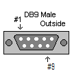
13 The MODport-102 has two serial ports. Port 1 operates the same as the MODport-101 serial port. Port 2 on the MODport-102 is a RS-232 only interface. The MODport-104 has four serial ports, each configurable through software as RS- 232, RS-422 or RS-485 interface. 2.7 DB9 Pin Configuration The RS-232 interfaces are configured as DTEs (Data Terminal Equipment). The connectors for all ports are DB-9 Male. Pin RS-232 RS-422 RS DCD RXD (-) 2 RXD RXD (+) 3 TXD TXD (+) D (+) 4 DTR TXD (-) D (-) 5 GND GND GND 6 DSR CTS (-) 7 RTS CTS (+) 8 CTS RTS (+) 9 RI RTS (-) 2.8 Serial Port Operational Modes Using the Manager software, the first serial port of MODport-10x can be set to Console, Default or Upgrade Mode. The serial ports can be configured for RS-232, RS-422 or RS-485 operation. The MODport-10X also can be set to Console Mode by placing all the DIP switches into the ON position Console Mode The console mode allows access to the MODport-10x setup menu. This is one way to reconfigure the default settings for the application. A serial connection is made between a COM port on the PC and the MODport-10x serial port 1 with a null modem cable. In console mode, the serial port defaults to an RS-232 interface. The serial port default settings are, baud rate 9600, 8 data bits, no parity, and 1 stop bit. HyperTerminal should be used for this type of setup. HyperTerminal s serial settings are configured the same as the mentioned default settings and must be set to VT100 emulation mode. The default settings are used when the first serial port is set to console mode regardless the actual configuration parameters are. MODport-10x Manual 7
 2 RXD RXD (+) 3 TXD TXD (+) D (+) 4 DTR TXD (-) D (-) 5 GND GND GND 6 DSR CTS (-) 7 RTS CTS (+) 8 CTS RTS (+) 9 RI RTS (-) 2.")
14 See Chapter 9 for console usage details Upgrade Mode The newest firmware can be upgraded to MODport-10x using the PC s serial port or the Virtual COM port. See Chapter 12 for upgrade details Default Mode When Default Mode is selected and the Gateway Properties are updated (saved), all configuration settings return to their default values RS-232 Mode The RS-232 supports 8 signals plus Ground and is configured as DTE like a computer. Signals are single ended and referenced to Ground. To use handshaking, Flow Control must be set to RTS/CTS during Configuration. Refer to the Pin out table for connections RS-422 Mode The RS-422 mode supports 4 signals with full duplex operation for Receive, Transmit, RTS (Request To Send) and CTS (Clear To Send). The data lines are in differential pairs. Ground provides a common mode reference. To use handshaking Flow Control must be set to RTS/CTS during configuration. Refer to the Pin out table for connections RS-485 Mode The RS-485 mode supports the Transmit and Receive Channels using 2-wire halfduplex operation. The data lines are differential pair Ground provides a common mode reference. Refer to the Pin out table for connections. RS-485 Receiver Biasing can be implemented from the MODport-10x if the network does not supply it. Remove the two side-cover screws of the MODBUS gateway, slide the cover off and re-position the bias jumpers to enable biasing (shorting). 8 MODport-10x Manual
 and CTS (Clear To Send). The data lines are in differential pairs.")

15 3 MODport-10x Software Installation It is recommended the user install the Manager software and do a search for all MODport-10xs connected to the LAN. When search is completed, a window will list the devices making them available for configuration. Configuring the MODport-10X to meet your LAN and application requirement is an easy process with the available setup menu in the Manager software. 3.1 New Installation The following procedure installs the MODport-10x Manager Software. 1. Inserting the MODport-10x CD in the CD-ROM will automatically launch the Install Shield Wizard. To manually start the software installation, select the Start button on the desktop. At the Run command line type D:start.exe Then select OK. The D: is the drive letter for the CD Rom. 2. The Install Shield Wizard window automatically displays to begin the setup procedure. 3. Select Next when the MODport-10x Setup window appears. MODport-10x Manual 9

16 4. In the Choose Destination Location window select Next to install the Manager software in the default location. Select Browse to install into a user selected directory. The installation progress will be shown until complete. 5. Select Finish when the Install Shield Wizard Complete screen appears. When the installation is complete the Install window closes allowing the user to access the Manager software in the program files. If loaded in the default location Go to Start/Programs/MODport/ MODport Manager to open. 10 MODport-10x Manual

17 Connect the MODport-10x to the LAN and apply power. The Run LED will flash indicating power has been applied and communications with the unit can begin; and the Link LED indicates an Ethernet connection has been made. 3.2 Updating an Existing Installation If an older version of the Manager software is already installed, the Modify, repair or remove the program window will appear when the installation process is initiated: The recommended procedure is to remove all installed components first. Once the software has been removed, install the new software. MODport-10x Manual 11

18 4 Using Manager Software The Manager software performs several functions: Searching for MODport-10x connected to the network Displaying and changing the configuration of MODport-10x Installing virtual COM ports on a computer Displaying and configuring virtual COM ports Uninstalling virtual COM ports on a computer Upgrading the MODport-10x firmware Monitoring Port Status Saving and Loading Configuration Files Once the MODport-10x is connected to the LAN the Manager software will be able to search the LAN for all connected MODport-10x servers and will display them in a window by name and IP address. 4.1 Searching LAN for MODport-10x 1. Select MODport-10x Manager in the program file menu. If the default location was selected during the installation the program will be found under Start/Programs/MODport. Select MODport Manager. As soon as the MODport-10x Manager opens it will initiate Searching Server and after a few seconds the MODBUS gateway List will display all (MODport-10x) MODBUS gateways on the local area network. 2. To manually initiate a search for servers, on the menu side bar double click the Searching Server button. The Search Setup box will appear. It provides two options for searching for servers on the network: Specify the IP address of the MODBUS gateway Search all reachable servers Enter the IP Address assigned to the desired MODBUS gateway or click Search all reachable servers, then OK. The Searching window is shown until all active MODBUS gateways on the LAN are listed in the MODBUS gateway List window. 12 MODport-10x Manual

19 4.2 Configuring Gateway Properties Highlight the MODBUS gateway in the MODBUS gateway List window and double click to open the Gateway Properties window. The Gateway Properties window is used to configure and store the Server configuration settings. Details for setting Properties are described in the next chapter. After configuring as needed, click Update to store the configuration in the server and click Yes to restart the server to make sure all settings are changed to conform to the desired application. MODport-10x Manual 13

20 5 Gateway Properties There are four ways to access the Gateway Properties and program the MODport-10x: Manager Software, Console mode, Telnet or Web Server. Instructions on how to move around in the user interface and change settings pertains to the Manager software are similar in others. 5.1 Server Configuration Server Name The server name is user configurable. It is recommended users with more than one MODport-10x connected to the LAN assign a new name to each. When the Manager software searches for servers on the LAN it will display the server name allowing the user to distinguish between MODport-10xs Serial Number Each MODport-10x has a unique serial number. This is fixed and cannot be changed. 14 MODport-10x Manual

21 5.1.3 Password Entering a password activates a security feature on the MODBUS gateway. Once a password is entered, it will be required to access the menu and make changes Version & Date The currently loaded version of the firmware, and when it was released, are shown here. 5.2 Network configuration DHCP DHCP servers are a part of numerous LAN management systems. The DHCP field has two selections, Enable or Disable. Arrow to the desired selection and select enter. When enabled, MODport-10x will send a DHCP request to the DHCP server, which will assign a dynamic IP address, netmask, and gateway to the MODport-10x. If a DHCP server is not available on the network the MODport-10x will time out after 10 MODport-10x Manual 15
22 seconds and the default values will remain. When DHCP is enabled, the IP address, Netmask and Gateway fields become inaccessible and cannot be changed by the user IP Address A static IP address can also be assigned in this section of the menu. A dynamic address assigned by the DHCP server may change if the MODport-10x loses the Ethernet connection or power is removed. The host (client) communication software requests a connection to the specific IP address of the MODBUS gateway. If the DHCP reassigns a different IP address the software will not be able to communicate with the hardware. It is recommended to use a static IP address. A static IP address is permanent and will not change unless changed in the menu. In most cases the network administrator establishes the static address to be used Netmask The default LAN netmask is configured for a Class C address. This may be reconfigured by the user Gateway The gateway IP address allows users to access the MODBUS gateway from outside the LAN MAC Address The MAC address is not adjustable. This is assigned in the factory. Every Ethernet device manufactured has it own unique MAC address Link Status Link status automatically displays the type of Ethernet connection. It will either display 10 BaseT or 100BaseTX in full duplex or half duplex. This will depend on the LAN, switches, hubs used in the LAN topology. 16 MODport-10x Manual
23 5.3 Serial Interface Configuration Serial Port This field indicates the number of the port for with MODBUS gateway properties are currently being displayed. Changing the number in this field will cause all the other fields to display the properties for the specified port. Note, however, that before changing ports, any change to properties must be Updated (Saved) or the MODBUS gateway will not retain them Baud Rate The serial port baud rate on the MODport-10x must match the serial baud rate of the connected device unless using Virtual COM mode. In Virtual COM mode the application program can setup this parameter on the fly by sending normal COM command and MODport-10X will set it on the fly as if MODport-10X s serial port is one of PC s COM port Data/Parity/Stop This setting will have to match the data format of the connected device unless using Virtual COM mode. In Virtual COM mode the application program can setup this parameter on the fly by sending normal COM command and MODport-10X will set it on the fly as if MODport-10X s serial port is one of PC s COM port. MODport-10x Manual 17
24 5.3.4 Flow Control The flow control setting must match the connected serial device unless using Virtual COM mode. In Virtual COM mode the application program can setup this parameter on the fly by sending normal COM command and MODport-10X will set it on the fly as if MODport-10X s serial port is one of PC s COM port Serial Port Mode This allows configuration of the MODBUS gateway for the following modes of operation: RS-232 When this mode is selected and the gateway is updated, the selected serial port will become a RS-232 serial port on the gateway. RS-422 When this mode is selected and the gateway is updated, the selected serial port will become a RS-422 serial port on the gateway. RS-485 When this mode is selected and the gateway is updated, the selected serial port will become a RS-485 serial port on the gateway. Console When this mode is selected and the gateway is updated, a PC running a communication program such as Hyperterminal can communicate with the MODBUS gateway via the Console Mode serial port (Port 1 on MODport-10x), displaying the Gateway Properties screen and allowing configuration of the gateway and its ports. Upgrade When this mode is selected and the gateway is updated, firmware can be uploaded into the MODBUS gateway via the Console Mode serial port or a virtual COM port mapped to the number of the Console Mode serial port. Default When this mode is selected and the gateway is updated, it will revert the gateway to its default configuration Operation Mode There are two operation modes MODBUS and bridge. In MODBUS mode, the gateway is function as MODBUS protocol translator. In bridge mode, the gateway is function as data forwarding between Ethernet interface and serial interface. Also the virtual COM only works with bridge mode. 18 MODport-10x Manual
25 5.4 MODBUS configuration Serial Format Serial format define the data format on the serial interface where it is RTU or ASCII. The default setting is RTU Character Timeout In the MODBUS RTU protocol, character timeout is used to signal the end of a message. If there is an improper timeout occurs during sending message time period, it will cause a CRC checksum error and the message will be discarded. To improve this situation, whenever MODport-10X receives a byte from its serial port, it will check the data in its buffer and estimate the message length. Base on the message length MODport-10X calculates CRC checksum. If the CRC checksum matches, we know that is the end of the message. Therefore even there is a timeout error with the message. MODport-10X can correctly parse the message and convert the MODBUS RTU packet into MODBUS TCP packet Message Timeout This parameter allows you to set the time during for MODport-10X to wait for the response message. When message timeout occurs, MODport-10X would response an exception to MODBUS master if generate exception is enabled Inactive Timeout Inactive timeout allows MODport-10X to tear down a TCP/IP connection when there is no activity for a period of time. In case there is a networks failure or power outage. MODport-10x Manual 19
26 All the TCP/IP connection resource would be occupied by previous connection that prevent from MODport-10X to accept further incoming connection Maximum Connection This parameter defines the number of TCP connection to the gateway in either MODBUS TCP master or slave mode. The maximum number of the connection is 8. When MODport-10X is set as gateway of TCP master to serial slave, it can accept Polling/Query from up to 8 different TCP masters. Each query will handle in sequence since MODBUS serial interface can only handle one query at a time. All other queries will be queued until the previous query is finished or timeout. MODport-10X can queue up to 8 queries. If there are more than 8 queries at one time, those queries will be discarded and eventually TCP master will get a timeout Gateway Type This parameter defines what kind of MODBUS devices which MODport-10X is connected to. There are two types of connection MODBUS TCP master to MODBUS serial slave. MODBUS TCP slave to MODBUS serial master. The default setting is MODBUS TCP master to MODBUS serial slave. Each serial port in MODport-10X can be configured into different gateway type Listening TCP port The default listening MODBUS TCP port number is 502. It is recommended to use port number larger than 1024, if use TCP port number other than 502. Since most of TCP port number under 1024 are used by particular protocol Use MBAP s UID or Use Specific UID If this parameter is enabled, MODport-10X will extract the UID in MBAP s header and convert the message into MODBUS serial format with the extracted UID. If this parameter is disabled, MODport-10X sends the converted message to MODBUS serial slave device with UID defined in the Use Specific UID field Generate exception When this parameter is enabled, MODport-10X will generate exception message when slave device does not response to the query command or message timeout Remote IP Address/filter 20 MODport-10x Manual
27 This is a security feature that is activated when the IP address of the desired client is programmed into the remote IP Address setting of the menu. This tells the MODport- 10x to communicate with only the listed IP address and to filter out all other requests for connection. This feature is only enabled at gateway type TCP Master to Serial Slave. The default setting is It is recommended not to change this setting until the application has been tested and is communicating properly. At that point the address filtering feature of the MODport-10x can be activated UID Range MODport-10X use UID range to map a query from a MODBUS serial master with an UID within this range to an IP address and a TCP port. This is only used when the gateway type is MODBUS TCP slave to MODBUS serial master Slave IP Address and TCP port This is only used when the gateway type is MODBUS TCP slave to MODBUS serial master. MODport-10X maps a message from MODBUS serial master to a MODBUS serial slave. 5.5 Bridge configuration When setup in bridge mode, MODport-10X does not convert MODBUS protocol between TCP and RTU/ASCII, it simply forward data between Ethernet interface and serial interface. MODport-10x Manual 21
28 5.5.1 Protocol Select TCP or UDP protocol. If the application does not require a UDP connection, select TCP. TCP guarantees reliable communication with error checking whereas UDP provides faster transmission, but no guarantees that data is received by the peer device. When UDP mode is chosen the Serial timeout, TCP alive timeout, Connection mode, Connection at, Maximum connection and Remote IP address fields are replaced with the following three fields: Destination IP address range, Port number and Source IP address range. In this mode the server can be configured to broadcast data to and receive data from multiple IP addresses. Four IP address range fields are provided Serial Timeout Default is 0, or no timeout. Setting timeout to any value between 1 and seconds activates it. If communications are idle for specified timeout value the serial server will reset and make itself available for another connection TCP Alive Timeout This monitors TCP activity. If TCP activity stops for the length of time specified in this field the connection will be closed. This field can be set to any value between 0 and 255 minutes. If zero, or no value, is entered into this field the server will not disconnect Connection Mode The Connection mode field has three options, Server, Client and Client (no heartbeat). When Client or Client (no heartbeat) is selected, the Connection at field automatically becomes active (allowing the user to select Power up or Data arrival). When using the Virtual COM Port feature, select Server. When using a TCP or UDP Socket program, select Server. When using Paired Mode communication between two serial servers set up one as a Client and the other as a Server. When connecting to a server that does not support Heartbeat, select Client (no heartbeat) Delimiter HEX1 and Delimiter HEX 2 These two fields allow the user to enter two ASCII characters (in hex format) that delimit the beginning and end of a message. When a message with both these delimiters is received at the serial port, the data contained in the serial buffer is placed 22 MODport-10x Manual
29 in an Ethernet packet and sent out the Ethernet port. If only Delimiter 1 is set (Delimiter 2 is zero or blank), upon receiving Delimiter 1 the MODport-10x will put all the data in the serial buffer in an Ethernet packet and send it out the Ethernet port. If serial data greater than 1 kilobyte is received it will automatically be placed in an Ethernet packet and sent out the Ethernet port Force Transmit This field allows the user to set a maximum time limit between transmissions of data. The value set in this field multiplied by 100 ms determines the Force Transmit time. When the elapsed time reaches the time configured in this field, the TCP/IP protocol will pack the data currently in the serial buffer into a packet and send it out the Ethernet port TCP/UDP Listening Port The TCP/UDP Port defines a communication port number. In all modes of operating, Virtual COM, Direct IP, and Paired modes, both the TCP/UDP Client and server port settings must match. For example the Virtual COM s default setting TCP/UDP Port # If the port # of the MODport-10x is changed to 4001, the Virtual COM TCP/UDP Port will have to be changed to Connection At When the Connection Mode field is set to Client or Client (no heartbeat), this field becomes active, allowing the MODport-10x (acting as a client) to connect to the server either on Power up or on Data Arrival (first character arriving) Maximum Connection This field allows the user to configure the Serial Server to have up to eight TCP connections Remote IP Address This is a security feature that is activated when the IP address of the desired client is programmed into the remote IP Address setting of the menu. This tells the MODport- 10x to communicate with only the listed IP address and to filter out all other requests for connection. The MODport-10x is setup in the menu as a TCP or UDP server to us this feature. MODport-10x Manual 23

30 The default setting is It is recommended not to change this setting until the application has been tested and is communicating properly. At that point the address filtering feature of the MODport-10x can be activated. 5.6 Update/Save Gateway Properties must be updated separately for each serial port. Updating varies slightly depending on which of the four configuration user interfaces are used Updating the Gateway Properties in Manager Software From the Gateway Properties screen, click the Update button to store the configuration settings for the currently selected port. The vcomui dialogue box will appear indicating you must restart the device before the new settings will take effect. Click Yes Saving Configuration Data in Console Mode or Telnet Saving (updating) Gateway Properties is done from the Configuration screen. Access the Configuration screen by tabbing through the list of screens on the left side of the window and highlighting Configuration. There are four options shown on the right side of the Configuration screen: Save, Default, Running and Reset. Use Tab, Backspace, or arrow keys to move the cursor to the option position, then press Enter. 24 MODport-10x Manual
31 Save stores the configuration data to the MODBUS gateway flash memory and resets it. Default restores the configuration data to factory default settings. Running restores the configuration data to the last values stored in the flash memory. Reset re-boots the MODBUS gateway, making it available for a client connection. MODport-10x Manual 25
32 5.6.3 Web Server Interface The Web Server interface provides the same updating options as Console Mode and Telnet. These are located at the bottom of all three Web Server pages. If a field is changed, you must click Save before leaving that page or the changes will be ignored. 26 MODport-10x Manual

33 6 Installing Virtual COM Port The Virtual COM Port feature allows Windows platform software using standard API calls to be used in an Ethernet application. Running the Install Virtual COM port software adds a COM Port in the Device Manager of the operating system. The COM port will look like a standard COM port to Windows software used in most applications allowing the software to open a connection with the serial port located anywhere on the LAN. When using the virtual COM port the MODport-10x is configured as a TCP or UDP Server. 1. On the Desk Top select Start/Programs/MODport/Install Virtual COM. 2. Select the Search all reachable servers check box, then click OK. 3. The Install Virtual COM program will automatically search the LAN for all available MODport-10x MODBUS gateways and display them in the Found Server window. Highlight the desired MODBUS gateway and click Install. MODport-10x Manual 27

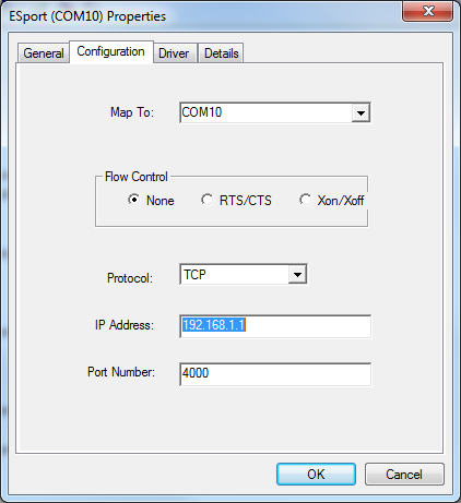
34 4. When the COMInst window opens select COM port # to map the MODBUS gateway to. The Flow Control, Protocol, IP Address, and Port Number will mirror the settings of the selected MODBUS gateway. Highlight the desired COM port # and select OK. If any settings are changed in this part of the Virtual COM setup it will only affect the settings in the operating system Device Manager. It will not change the settings in the MODport-10x. The settings of the Virtual COM port in the Device Manager and the MODport-10x Configuration menu must match. If the settings do not, the software connecting to the Virtual COM port will be unsuccessful in opening the COM port. 5. Note: In Windows XP a Hardware Installation window stating that the drivers have not been tested by Microsoft may appear. Select Continue Anyway to proceed with the installation. 6. When finish, click Cancel on the Found Server window. To confirm installation, go to the Device Manager and select Ports (COM & LPT). The installed Virtual COM port will be displayed as MODport-10x COM#. 28 MODport-10x Manual

35 MODport-10x Manual 29

36 7 Configuring Virtual COM Port The Virtual COM port can be configured in the Device Manager of the operating system or the Manager software. In either case the IP Address, Port #, Protocol, and Flow Control settings must match the MODport-10x settings for the software to open the Virtual COM port. 7.1 Configuration with Manager Software 1. At the Desk Top select Start/Programs/MODport/MODport Manager. Double click the Virtual COM Configuration button. 2. Double click the COM # displayed in the screen to open the configuration window. 30 MODport-10x Manual
37 3. Make the adjustments and select OK to complete the changes. 7.2 Configuration with Device Manager 1. On the Desk Top select Start/Settings/Control Panel. Select the System Icon when the Control Panel window opens. 2. In the System Properties window select the Device Manager button. 3. In the Device Manager select the + button next to Ports (COM & LPT) to expand and see the MODport (COM #). Double click MODport (COM #) to open the Properties window. 4. Select the Configuration tab. From here the same settings found in the MODport Manager can be adjusted. MODport-10x Manual 31
38 32 MODport-10x Manual

39 8 Uninstalling the Virtual COM Port The MODport Manager Software Uninstall Virtual Com port feature will remove the mapped COM port in the Device Manager of Windows 2000 and XP operating systems. It may also be removed in the Device Manager of Windows 98, ME, NT, 2000, and XP. Windows 98 users will also find a Remove Virtual COM feature in the programs file. 8.1 Removing the Virtual COM port with Manager Software 1. At the Desk Top select Start/Programs/MODport/MODport Manager 2. In the Manager window select Virtual COM Configuration. Highlight the mapped COM port number to be removed. 3. Select Uninstall Virtual COM button. The Manager will ask for confirmation. Select Yes to complete the uninstall procedure. MODport-10x Manual 33
 to expand. 3.")
40 8.2 Removing the Virtual COM Port using Device Manager The screen shots were taken from a Windows XP operating system 1. On the Desktop select Start/Settings/Control Panel. Select the System icon when the Manager window opens. 2. Select Device Manager in the Systems Properties window. In the Device Manger window select the + next to Ports (COM & LPT) to expand. 3. Highlight MODport (COM #) to be removed, go the Action tab at the top of window and select uninstall. A confirm Device Removal window will appear. Select OK to proceed. 34 MODport-10x Manual
41 4. The MODport COM # will be removed and the Device Manager window will refresh and display the remaining COM ports. MODport-10x Manual 35
42 9 Using Console Before the MODport is installed on a LAN the Console Mode can be used to change the settings from the defaults. Connect a null modem cable between the serial port on the MODport and the COM port on the PC. Apply power to the MODport. The Run LED will flash. See chapter 5 for details on Gateway Properties. Using Hyper Terminal open the connected PC COM port at a baud rate of 9600, Data bits 8, Parity None, Stop bits 1, and Flow control None. Ensure all the DIP switches are in the ON position for MODport. To view the menu hit the space bar. There are six Console Mode screens: Server, Network, Serial Mode, Operation, Monitor and Configuration. Tab, Back Space and arrow keys can be used to highlight the desired function on the screen list. Pressing Enter moves the cursor to the first field with the current screen. The configuration fields can be changed by pressing Enter and selecting from the list that appears. The Escape key moves the cursor back to the screen list. Pressing the Space Bar refreshes the page. 36 MODport-10x Manual

43 MODport-10x Manual 37

44 Once all the changes have been made move to the Configuration screen, select Save and press Enter. The restart message will appear. Select Yes to save changes. This is necessary to write the settings to the server. 38 MODport-10x Manual
45 10 Using Telnet Telnet can be used to configure the MODBUS gateway from any PC on the LAN. The Telnet window displays the same configuration information shown in Console Mode and allows Gateway Properties to be configured. See chapter 5 for details on Gateway Properties. Ensure the PC and MODport-10x are connected to the LAN, and the MODBUS gateway is in RS-232, RS-422 or RS-485 mode before you can telnet to it and access the configuration screens. From the Desktop, click Start, then Run. The Run dialogue box will open. Type in Telnet and the IP address of the MODBUS gateway to be configured, then click OK. The Telnet window will open and the Server screen will appear. See chapter 9 for configuration screens and navigation. Please note that, telnet console is disabled when serial console is enabled. MODport-10x Manual 39

46 11 Using Web Server The Web Server can be used to configure the MODBUS gateway from any web browser software (such as Internet Explorer). Gateway Properties can be set up using three browser pages. See chapter 5 for details on Gateway Properties. In Internet Explorer type the IP Address of the MODBUS gateway into the address field near the top of the window and press the Enter key. The following window will appear: Navigate and change properties as required using the mouse and keyboard. To change serial port properties, click Serial Port on the left side of the browser window. The following page will appear: 40 MODport-10x Manual

47 To change other operational properties, click Operation on the left side of the browser window. The following page will appear: MODport-10x Manual 41

48 Click Save to store changes to the MODBUS gateway. Settings for each Port must be saved separately. 42 MODport-10x Manual

49 12 Upgrading the MODBUS gateway Firmware New firmware may be available at times on our web site and may be downloaded and flashed to the MODport-10x currently in use. The user can upgrade using a direct connection to the MODport-10x serial port or the Virtual COM port feature. 1. Download the new upgrade.hex file and place in a folder. 2. Set MODport-10x to Upgrade mode. Ensure that the DIP switches on MODport-101 or MODport-102 are all in the OFF position and make sure MODport is in bridge mode. 3. Connect a null modem cable between the PC and the MODport-10x. When using the Virtual COM mode a cable is not required. 4. Open the Manager software and select the Firmware Upgrade button. 5. In the Serial Port selection options select the COM port number used to connect the PC to the MODport-10x. If using the Virtual COM port select that number. 6. Select Browse, find the location of the firmware, select Open, and then select the upgrade button. 7. A serial menu will appear allowing the upgrade software to be setup the same as the MODport-10x serial settings. The settings must match or the upgrade will fail. MODport-10x Manual 43

50 8. A window showing the Upgrade progress will appear followed by a window indicating the Upgrade was successful. 9. MODport-10x will reset itself to complete the upgrade process. 44 MODport-10x Manual
51 13 Troubleshooting Q: Why sometimes Hyperterminal loses characters or display funny characters? A: This happens when you open a new Hyperterminal connection and keep inputting the same character. The reason is before Hyperterminal receiving two different characters from the other end, its status is Auto detect, and your port settings haven t fully take effect, so the transferred data is not predicable. To solve this problem, input two different characters from the other end, then the Hyperterminal status will show your port settings such as N-1, save this Hyperterminal connection. Next you open your saved Hyperterminal connection, everything will be fine. Q: What should I do when I forget the IP address or baud rate setting of a MODport- 10x? A: You can use the searching capability to get the information of all MODport-10x on the network. Double clicks on the searched result will show the detail configuration parameters of the device. Q: Why I cannot open virtual COMx? A: The server settings and virtual COMx settings may not match, please make sure their IP address, protocol, port and flow control mode are the same, and the remote IP address should be the host IP address. Besides the MODport-10x cannot be at Console mode. Q: Why the arrow keys of hyperterminal in Windows 2000 do not work in Console mode and telnet? A: Please download new version of hyperterminal. The hyperterminal comes with Windows 2000 does not send the arrow key code properly. Q: Why I am unable to change the parameters of port 1? A: Serial port 1 is designated console port. The default setting for the console port is N-1. If the serial port 1 is set to console port. It will use the default value that is why it does response to the change. Please check hardware switch or Gateway Properties page to see if the serial port mode of the port1 is set to console. Please change it to other mode then its parameter can be changed. Q: Why the parameters in the web console are different than those in the Gateway Properties of management utility? A: The edited parameters in the web console only take effect after reset MODport. Web console show the edited configuration while in the management utility show the running configuration. That is why they might appear differently It is not recommended to edit server's configuration using two different tools at the same time. Because all change could be over-written by other method. MODport-10x Manual 45
52 46 MODport-10x Manual
MODBUS TCP to RTU/ASCII Gateway. User s Manual
 MODBUS TCP to RTU/ASCII Gateway User s Manual 1 INTRODUCTION... 1 1.1 FEATURES... 2 1.2 PRODUCT SPECIFICATIONS... 3 1.3 DEFAULT SETTINGS... 4 2 MAKING THE HARDWARE CONNECTIONS... 5 2.1 POWER CONNECTION...
TRP-C31M MODBUS TCP to RTU/ASCII Gateway
 TRP-C31M MODBUS TCP to RTU/ASCII Gateway User s Manual Printed Feb. 2007 Rev 1.0 Trycom Technology Co., Ltd 1F, No.2-11, Sihu street, Yingge Township, Taipei, Taiwan ROC Tel: 886-2-86781191, Fax: 886-2-86781172
One Port Serial Server Users Manual Model ESP901, ESP901E
 One Port Serial Server Users Manual Model ESP901, ESP901E Documentation Number: ESP901-2303 International Headquarters B&B Electronics Mfg. Co. Inc. 707 Dayton Road -- P.O. Box 1040 -- Ottawa, IL 61350
IP SERIAL DEVICE SERVER
 IP SERIAL DEVICE SERVER ( 1 / 2 / 4 serial port ) Installation guide And User manual Version 1.0 1Introduction... 5 1.1Direct IP mode...5 1.2Virtual COM mode...5 1.3Paired mode...6 1.4Heart beat... 6
IP Serial Server. User Manual
 IP Serial Server IPS-101 (1-port) IPS-102 (2-port) IPS-201 (1-port) IPS-202 (2-port) IPS-204 (4-port) User Manual V2.0 2009.03.09 Page: 1 / 62 Copyright This document contains proprietary information that
TCP/IP MODULE CA-ETHR-A INSTALLATION MANUAL
 TCP/IP MODULE CA-ETHR-A INSTALLATION MANUAL w w w. c d v g r o u p. c o m CA-ETHR-A: TCP/IP Module Installation Manual Page Table of Contents Introduction...5 Hardware Components... 6 Technical Specifications...
ENET-710. ENET-710 - Ethernet Module ENET-710 JAN / 06 FOUNDATION
 ENET-710 ENET-710 - Ethernet Module JAN / 06 ENET-710 FOUNDATION E N E T 7 1 0 ME smar www.smar.com Specifications and information are subject to change without notice. Up-to-date address information is
BIT COMMANDER. Serial RS232 / RS485 to Ethernet Converter
 BIT COMMANDER Serial RS232 / RS485 to Ethernet Converter (Part US2000A) Copyrights U.S. Converters 1 Contents Overview and Features... 3 Functions..5 TCP Server Mode... 5 Httpd Client Mode.5 TCP Auto mode....6
1 Serial RS232 to Ethernet Adapter Installation Guide
 Installation Guide 10/100 Mbps LED (amber color ) Link/Activity LED (green color ) 1. Introduction Thank you for purchasing this 1-port RS232 to Ethernet Adapter (hereinafter referred to as Adapter ).
User s Manual TCP/IP TO RS-232/422/485 CONVERTER. 1.1 Introduction. 1.2 Main features. Dynamic DNS
 MODEL ATC-2000 TCP/IP TO RS-232/422/485 CONVERTER User s Manual 1.1 Introduction The ATC-2000 is a RS232/RS485 to TCP/IP converter integrated with a robust system and network management features designed
Setup Manual and Programming Reference. RGA Ethernet Adapter. Stanford Research Systems. Revision 1.05 (11/2010)
") Setup Manual and Programming Reference Stanford Research Systems Revision 1.05 (11/2010) Certification Stanford Research Systems certifies that this product met its published specifications at the time
Setup Manual and Programming Reference Stanford Research Systems Revision 1.05 (11/2010) Certification Stanford Research Systems certifies that this product met its published specifications at the time
USER GUIDE. Ethernet Configuration Guide (Lantronix) P/N: 2900-300321 Rev 6
 P/N: 2900-300321 Rev 6") KRAMER ELECTRONICS LTD. USER GUIDE Ethernet Configuration Guide (Lantronix) P/N: 2900-300321 Rev 6 Contents 1 Connecting to the Kramer Device via the Ethernet Port 1 1.1 Connecting the Ethernet Port Directly
KRAMER ELECTRONICS LTD. USER GUIDE Ethernet Configuration Guide (Lantronix) P/N: 2900-300321 Rev 6 Contents 1 Connecting to the Kramer Device via the Ethernet Port 1 1.1 Connecting the Ethernet Port Directly
RS-232/422/485, Power over Ethernet
 IP-COM-M IP-COMi-M IP-COM-M PoE IP-COMi-M PoE RS-232 RS-232/422/485 RS-232, Power over Ethernet RS-232/422/485, Power over Ethernet Edition: September 2012 The computer programs provided with the hardware
Serial over Ethernet Device Server. User s Manual
 Serial over Ethernet Device Server User s Manual Second Edition, November 2005 SUNIX Co., Ltd. Tel : +886-2-8913-1987 Fax: +886-2-8913-1986 Http://www.sunix.com.tw [email protected] Serial over Ethernet
To perform Ethernet setup and communication verification, first perform RS232 setup and communication verification:
 PURPOSE Verify that communication is established for the following products programming option (488.2 compliant, SCPI only): DCS - M9C & DCS M130, DLM M9E & DLM-M9G & DLM M130, DHP - M9D, P series, SG,
LS-101 LAN to Serial Device server. User s Manual
 LS-101 LAN to Serial Device server User s Manual Revision History Revision No Date Author Remarks 0.1 August 29, 2001 IDC Initial document INTRODUCTION Overview Almost all instruments and most industrial
TCP/IP Converter DDS EX-9132 Operation Manual for 8051 Series
 TCP/IP Converter DDS EX-9132 Operation Manual for 8051 Series First Edition, March 2005 Table of Contents 1. Introduction 3 Overview 4 Package Checklist 5 Block Diagram 6 Features 7 Product Specifications
Operation Manual of EX-9132C-2. Serial to TCP/IP Converter
 Operation Manual of EX-9132C-2 Serial to TCP/IP Converter Version 1.2.1 20th May 2013 Table of Contents 1. Introduction 3 Overview 4 Package Checklist 4 Block Diagram 5 Features 6 Product Specifications
Ethernet Interface Manual Thermal / Label Printer. Rev. 1.01 Metapace T-1. Metapace T-2 Metapace L-1 Metapace L-2
 Ethernet Interface Manual Thermal / Label Printer Rev. 1.01 Metapace T-1 Metapace T-2 Metapace L-1 Metapace L-2 Table of contents 1. Interface setting Guiding...3 2. Manual Information...4 3. Interface
Serial Over IP Ethernet Device Server
 NETRS2321E NETRS2321EEU NETRS2321EGB Instruction Manual Serial Over IP Ethernet Device Server 1 Port RS-232/422/485 Serial over IP Ethernet Device Server Manual Revision:10/13/2010 For the most up-to-date
Modbus and ION Technology
 70072-0104-14 TECHNICAL 06/2009 Modbus and ION Technology Modicon Modbus is a communications protocol widely used in process control industries such as manufacturing. PowerLogic ION meters are compatible
NPort DE-311 Hardware Installation Guide
 NPort DE-311 Hardware Installation Guide Fourth Edition, June 2008 www.moxa.com/product 2008 Moxa Inc., all rights reserved. Reproduction without permission is prohibited. NPort DE-311 Hardware Installation
3.1 RS-232/422/485 Pinout:PORT1-4(RJ-45) RJ-45 RS-232 RS-422 RS-485 PIN1 TXD PIN2 RXD PIN3 GND PIN4 PIN5 T+ 485+ PIN6 T- 485- PIN7 R+ PIN8 R-
 RJ-45 RS-232 RS-422 RS-485 PIN1 TXD PIN2 RXD PIN3 GND PIN4 PIN5 T+ 485+ PIN6 T- 485- PIN7 R+ PIN8 R-") MODEL ATC-2004 TCP/IP TO RS-232/422/485 CONVERTER User s Manual 1.1 Introduction The ATC-2004 is a 4 Port RS232/RS485 to TCP/IP converter integrated with a robust system and network management features
MODEL ATC-2004 TCP/IP TO RS-232/422/485 CONVERTER User s Manual 1.1 Introduction The ATC-2004 is a 4 Port RS232/RS485 to TCP/IP converter integrated with a robust system and network management features
NPort 6110 Modbus/TCP to Serial Communication Gateway
 1 NPort 6110 Modbus/TCP to Serial Communication Gateway User s Manual Second Edition, November 2004 Moxa Technologies Co., Ltd. Tel: +886-2-8919-1230 Fax: +886-2-8919-1231 Web: www.moxa.com MOXA Technical
How to setup a serial Bluetooth adapter Master Guide
 How to setup a serial Bluetooth adapter Master Guide Nordfield.com Our serial Bluetooth adapters part UCBT232B and UCBT232EXA can be setup and paired using a Bluetooth management software called BlueSoleil
EMG Ethernet Modbus Gateway User Manual
 EMG Ethernet Modbus Gateway User Manual Rev 2.2 07/2010 CONTENTS 1. Introduction 1.1. General Features 1.2 Installing the Drivers 2. Configuration 2.1 Main Device Parameters 2.1.1 RS485 Serial Communication
EZ-View Network Communications Guide www.cszindustrial.com
 Network Communications Guide EzView Network Communications Guide RevB July 2013 (V2.2) Supersedes: RevA (May 2011) Cincinnati Sub-Zero Products, LLC 513-772-8810 12011 Mosteller Road Cincinnati, Ohio 45241
LBNP16312. RS-232/485/422 serial device server. User manual
 Tu Sitio de Automatización! LBNP16312 RS-232/485/422 serial device server User manual Summarize-----------------------------------------------------------------------------14-3 Package checklist---------------------------------------------------------------------14-3
Prestige 324. Prestige 324. Intelligent Broadband Sharing Gateway. Version 3.60 January 2003 Quick Start Guide
 Prestige 324 Intelligent Broadband Sharing Gateway Version 3.60 January 2003 Quick Start Guide 1 Introducing the Prestige The Prestige is a broadband sharing gateway with a built-in four-port 10/100 Mbps
PCMCIA 1 Port RS232 2.1 EDITION OCTOBER 1999
 232 232232 PCMCIA 1 Port RS232 2.1 EDITION OCTOBER 1999 Guarantee. FULL 36 MONTHS GUARANTEE. We guarantee your interface card for a full 36 months from purchase, parts and labour, provided it has been
The following sections describe the Gateway configuration pages in the SBG1000 Setup Program.
 Configuration Gateway > WAN Page Gateway: LAN nat config Page Gateway: LAN dhcp server config Page Gateway LOG Page Preparing the Network Preparing the Computers for TCP/IP Networking Configuring TCP/IP
How To Set Up A Modbus Cda On A Pc Or Maca (Powerline) With A Powerline (Powergen) And A Powergen (Powerbee) (Powernet) (Operating System) (Control Microsci
 With A Powerline (Powergen) And A Powergen (Powerbee) (Powernet) (Operating System) (Control Microsci") Firmware Loader User Manual CONTROL MICROSYSTEMS SCADA products... for the distance 48 Steacie Drive Telephone: 613-591-1943 Kanata, Ontario Facsimile: 613-591-1022 K2K 2A9 Technical Support: 888-226-6876
Firmware Loader User Manual CONTROL MICROSYSTEMS SCADA products... for the distance 48 Steacie Drive Telephone: 613-591-1943 Kanata, Ontario Facsimile: 613-591-1022 K2K 2A9 Technical Support: 888-226-6876
Prestige 324 Quick Start Guide. Prestige 324. Intelligent Broadband Sharing Gateway. Version V3.61(JF.0) May 2004 Quick Start Guide
 May 2004 Quick Start Guide") Prestige 324 Intelligent Broadband Sharing Gateway Version V3.61(JF.0) May 2004 Quick Start Guide 1 1 Introducing the Prestige The Prestige is a broadband sharing gateway with a built-in four-port 10/100
Prestige 324 Intelligent Broadband Sharing Gateway Version V3.61(JF.0) May 2004 Quick Start Guide 1 1 Introducing the Prestige The Prestige is a broadband sharing gateway with a built-in four-port 10/100
16-Port RS232 to USB2.0 High Speed Multi Serial Adapter (w/ Metal Case) Installation Guide
 Installation Guide") 16-Port RS232 to USB2.0 High Speed Multi Serial Adapter (w/ Metal Case) Installation Guide 1. Introduction Thank you for purchasing this 16-Port RS232 to USB2.0 High Speed Multi Serial Adapter. It is an
16-Port RS232 to USB2.0 High Speed Multi Serial Adapter (w/ Metal Case) Installation Guide 1. Introduction Thank you for purchasing this 16-Port RS232 to USB2.0 High Speed Multi Serial Adapter. It is an
WRE6505. User s Guide. Quick Start Guide. Wireless AC750 Range Extender. Default Login Details. Version 1.00 Edition 1, 4 2014
 WRE6505 Wireless AC750 Range Extender Version 1.00 Edition 1, 4 2014 2.4G 5G Quick Start Guide User s Guide Default Login Details LAN IP Address 192.168.1.2 User Name admin www.zyxel.com Password 1234
Wireless LAN 802.11g USB Adapter
 Wireless LAN 802.11g USB Adapter User s Guide Version 1.0 User s Guide 0 Copyright statement No part of this publication may be reproduced, stored in a retrieval system, or transmitted in any form or by
RS-232/422/485 to 10/100Base-TX Device Server / Managed Media Converter (IRF-633) User s Manual
 User s Manual") RS-232/422/485 to 10/100Base-TX Device Server / Managed Media Converter (IRF-633) User s Manual COPYRIGHT All rights reserved. No part of this publication may be reproduced, stored in a retrieval system,
RS-232/422/485 to 10/100Base-TX Device Server / Managed Media Converter (IRF-633) User s Manual COPYRIGHT All rights reserved. No part of this publication may be reproduced, stored in a retrieval system,
ProSAFE 8-Port and 16-Port Gigabit Click Switch
 ProSAFE 8-Port and 16-Port Gigabit Click Switch Model GSS108E and GSS116E User Manual March 2015 202-11520-01 350 East Plumeria Drive San Jose, CA 95134 USA Support Thank you for selecting NETGEAR products.
Programming and Using the Courier V.Everything Modem for Remote Operation of DDF6000
 Programming and Using the Courier V.Everything Modem for Remote Operation of DDF6000 1.0 Introduction A Technical Application Note from Doppler System July 5, 1999 Version 3.x of the DDF6000, running version
Link Link sys E3000 sys RE1000
 User Guide High Performance Extender Wireless-N Router Linksys Linksys RE1000 E3000Wireless-N Table of Contents Contents Chapter 1: Product Overview 1 Front 1 Top 1 Bottom 1 Back 2 Chapter 2: Advanced
Atop ABLELink Ethernet-Serial Server GW51C- MAXI
 Atop ABLELink Ethernet-Serial Server GW51C- MAXI User Manual Version 1.1 Updated on 2004/08/18 Tel: 886-3-5508137 Fax: 886-3-5508131 www.atop.com.tw IMPORTANT ANNOUNCEMENT The information contained in
Chapter 10 Troubleshooting
 Chapter 10 Troubleshooting This chapter provides troubleshooting tips and information for your ProSafe Dual WAN Gigabit Firewall with SSL & IPsec VPN. After each problem description, instructions are provided
LINDY ELECTRONICS LIMITED & LINDY-ELEKTRONIK GMBH - SECOND EDITION
 RS-422/485 PCI Card User Manual English No. 51200 (2 Port) No. 51202 (4 Port) No. 51204 (8 Port) www.lindy.com LINDY ELECTRONICS LIMITED & LINDY-ELEKTRONIK GMBH - SECOND EDITION (Nov 2005) 1.0 Introduction
Broadband Router ESG-103. User s Guide
 Broadband Router ESG-103 User s Guide FCC Warning This equipment has been tested and found to comply with the limits for Class A & Class B digital device, pursuant to Part 15 of the FCC rules. These limits
HWg-STE HWg-STE PoE MANUAL
 HWg-STE HWg-STE PoE MANUAL www.hw-group.com Page 2 HWg-STE connectors LED indicators Green: Power & Mode Yellow: Link & Activity SENSORS S1 and S2 ports for connecting temperature or humidity sensors.
USER MANUAL GUIMGR Graphical User Interface Manager for FRM301/FRM401 Media Racks
 USER MANUAL GUIMGR Graphical User Interface Manager for FRM301/FRM401 Media Racks CTC Union Technologies Co., Ltd. Far Eastern Vienna Technology Center (Neihu Technology Park) 8F, No. 60 Zhouzi St. Neihu,
ACU-1000 Manual Addendum Replacement of CPM-2 with CPM-4
 ACU-1000 Manual Addendum Replacement of CPM-2 with CPM-4 1 PURPOSE:... 1 2 CPM-4/CPM-2 COMPATIBILITY... 2 2.1 NETWORK CABLES... 2 2.2 FACTORY DEFAULT SETTINGS... 2 2.3 CHANGING THE RS-232 SERIAL PORT BAUD
Operation Manual of EX9132C-RS485. Serial to TCP/IP Converter
 Operation Manual of EX9132C-RS485 Serial to TCP/IP Converter Version 1.0 27th May 2014 Table of Contents 1. Introduction 3 Overview 4 Package Checklist 4 Block Diagram 5 Product Features 7 Product Specifications
Secure Ethernet Gateway SEG-1 and SEG-M for IEI Access Systems Installation Manual
 Secure Ethernet Gateway SEG-1 and SEG-M for IEI Access Systems Installation Manual Section 1: Introduction SECURITY WARNING: New SEG's shipped after April 2008 will have Telnet setup option enabled by
WHQL Certification Approval...2 User Interface...3 SUNIX s COMLab..4
 INDEX WHQL Certification Approval...2 User Interface....3 SUNIX s COMLab..4 1.0 Introduction...5 2.0 Specification..5 2.1 Features 2.2 Universal Serial PCI Card 2.3 RS-232 Specification 2.4 Low Profile
Follow these steps to prepare the module and evaluation board for testing.
 2 Getting Started 2.1. Hardware Installation Procedure Follow these steps to prepare the module and evaluation board for testing. STEP1: Plug the EG-SR-7100A module into the sockets on the test board.
RN-XV-RD2 Evaluation Board
 RN-XV-RD2 Evaluation Board 2012 Roving Networks. All rights reserved. -1.01Version 1.0 9/28/2012 USER MANUAL OVERVIEW This document describes the hardware and software setup for Roving Networks RN-XV-RD2
Vantage RADIUS 50. Quick Start Guide Version 1.0 3/2005
 Vantage RADIUS 50 Quick Start Guide Version 1.0 3/2005 1 Introducing Vantage RADIUS 50 The Vantage RADIUS (Remote Authentication Dial-In User Service) 50 (referred to in this guide as Vantage RADIUS)
Application Note 2. Using the TCPDIAL & TCPPERM Commands to Connect Two TransPort router Serial Interfaces Over TCP/IP.
 Application Note 2 Using the TCPDIAL & TCPPERM Commands to Connect Two TransPort router Serial Interfaces Over TCP/IP. Reverse Telnet or Serial Terminal Server MultiTX feature UK Support March 2014 1 Contents
Serial-Ethernet Server STE-501C. User s Manual
 Serial-Ethernet Server User s Manual Version 1.3 IMPORTANT ANNOUNCEMENT The information contained in this document is the property of Aaxeon Technologies, LLC and is supplied for the sole purpose of the
User Manual. EtherUSB
 User Manual EtherUSB USB Ethernet Access Point for PDA V 2.0 Clarinet Systems, Inc. Clarinet Systems, Inc. http://www.clarinetsys.com Page 1 Publication Revision No. Control Table Rev. No. Date Contents
ZyWALL 5. Internet Security Appliance. Quick Start Guide Version 3.62 (XD.0) May 2004
 May 2004") ZyWALL 5 Internet Security Appliance Quick Start Guide Version 3.62 (XD.0) May 2004 Introducing the ZyWALL The ZyWALL 5 is the ideal secure gateway for all data passing between the Internet and the LAN.
ZyWALL 5 Internet Security Appliance Quick Start Guide Version 3.62 (XD.0) May 2004 Introducing the ZyWALL The ZyWALL 5 is the ideal secure gateway for all data passing between the Internet and the LAN.
2012 uptimedevices.com
 2012 uptimedevices.com Contents Product Overview...3 Installation...4 Web Interface Orientation...5 Web Interface (Login Screen)...6 Summary Screen...7 Sensors Screen...8 Sensor Names...9 Graph...10 Alerts
Prestige 650R-31/33 Read Me First
 Prestige 650R-31/33 Read Me First Prestige Rear Panel Connections PORT DSL CONSOLE LAN 10/100M POWER Connect to a telephone jack using a telephone wire. CONNECTION Connect to a serial port (COM port) on
ModBus Server - KNX. Gateway for integration of KNX equipment into Modbus (RTU and TCP) control systems.
 control systems.") IntesisBox ModBus Server - KNX Gateway for integration of KNX equipment into Modbus (RTU and TCP) control systems. Integrate KNX based lighting control into your SCADA, BMS, PLC "talking" Modbus. Master
IntesisBox ModBus Server - KNX Gateway for integration of KNX equipment into Modbus (RTU and TCP) control systems. Integrate KNX based lighting control into your SCADA, BMS, PLC "talking" Modbus. Master
Schneider OS-Loader usage via Ethernet or USB.
 LHC Gas Systems 28 th February, 2007 Schneider OS-Loader usage via Ethernet or USB. Jacques ROCHEZ - IT/CO/FE Abstract This document is a guideline on how to configure correctly a PC for the use of the
Model 2120 Single Port RS-232 Terminal Server Frequently Asked Questions
 Applications What are some of the applications for the Model 2120 Single Port Terminal Server? The Patton Single Port RS-232 Terminal Server provides the ability to bring virtually any RS-232 device onto
ethernet connection For more information about the printer's ethernet feature, click the topic below: ethernet lights network configuration page
 ethernet table of contents ethernet connection The printer's built-in ethernet feature allows you to connect the printer directly to an ethernet network without the need for an external print server. For
H0/H2/H4 -ECOM100 DHCP & HTML Configuration. H0/H2/H4--ECOM100 DHCP Disabling DHCP and Assigning a Static IP Address Using HTML Configuration
 H0/H2/H4 -ECOM100 DHCP & HTML 6 H0/H2/H4--ECOM100 DHCP Disabling DHCP and Assigning a Static IP Address Using HTML 6-2 H0/H2/H4 -ECOM100 DHCP DHCP Issues The H0/H2/H4--ECOM100 is configured at the factory
T3 Mux M13 Multiplexer
 T3 Mux M13 Multiplexer User Manual [Type the abstract of the document here. The abstract is typically a short summary of the contents of the document. Type the abstract of the document here. The abstract
Prestige 202H Plus. Quick Start Guide. ISDN Internet Access Router. Version 3.40 12/2004
 Prestige 202H Plus ISDN Internet Access Router Quick Start Guide Version 3.40 12/2004 Table of Contents 1 Introducing the Prestige...3 2 Hardware Installation...4 2.1 Rear Panel...4 2.2 The Front Panel
Prestige 623R-T. Quick Start Guide. ADSL Dual-link Router. Version 3.40
 Prestige 623R-T ADSL Dual-link Router Quick Start Guide Version 3.40 February 2004 Introducing the Prestige The Prestige 623R-T ADSL Dual-link Router is the ideal all-in-one device for small networks connecting
Modbus Communications for PanelView Terminals
 User Guide Modbus Communications for PanelView Terminals Introduction This document describes how to connect and configure communications for the Modbus versions of the PanelView terminals. This document
VSCOM USB PRO Series Industrial I/O Adapters
 VSCOM USB PRO Series Industrial I/O Adapters 1.Introduction The VSCOM USB PRO Series Industrial I/O Adapters are advanced USB to Serial Adapters that connect to 1, 2, 4 or 8 RS-232/422/485 serial devices.
Networking. General networking. Networking overview. Common home network configurations. Wired network example. Wireless network examples
 Networking General networking Networking overview A network is a collection of devices such as computers, printers, Ethernet hubs, wireless access points, and routers connected together for communication
Router Setup Manual. NETGEAR, Inc. 4500 Great America Parkway Santa Clara, CA 95054 USA 208-10060-01 2006-03-17
 NETGEAR, Inc. 4500 Great America Parkway Santa Clara, CA 95054 USA 208-10060-01 2006-03-17 2006 by NETGEAR, Inc. All rights reserved. Trademarks NETGEAR is a trademark of Netgear, Inc. Microsoft, Windows,
Wireless Router Setup Manual
 Wireless Router Setup Manual NETGEAR, Inc. 4500 Great America Parkway Santa Clara, CA 95054 USA 208-10082-02 2006-04 2006 by NETGEAR, Inc. All rights reserved. Trademarks NETGEAR is a trademark of Netgear,
User Manual Network Interface
 User Manual Network Interface Rev. 1.00 SRP-350plusll SRP-352plusll http://www.bixolon.com Table of Contents 1. Manual Information...3 2. Specifications...3 2-1 Hardware version...3 2-2 Configuration Tool...3
User Manual Revision 1.400 English Converter / Adapter Ethernet to RS232 / RS485 (Order Code: HD67038-2 HD67038-2-M HD67038-25 HD67038-25-M)
") Document code: MN67038-2_ENG Revision 1.400 Page 1 of 25 User Manual Revision 1.400 English Converter / Adapter Ethernet to RS232 / RS485 (Order Code: HD67038-2 HD67038-2-M HD67038-25 HD67038-25-M) for
Document code: MN67038-2_ENG Revision 1.400 Page 1 of 25 User Manual Revision 1.400 English Converter / Adapter Ethernet to RS232 / RS485 (Order Code: HD67038-2 HD67038-2-M HD67038-25 HD67038-25-M) for
TDP43ME NetPS. Network Printer Server. Control Center. for Ethernet Module
 Panduit Corp. 2010 TDP43ME NetPS PA26306A01 Rev. 01 11-2010 Network Printer Server Control Center for Ethernet Module NOTE: In the interest of higher quality and value, Panduit products are continually
Linksys Gateway SPA2100-SU Manual
 Linksys Gateway SPA2100-SU Manual Manuel de l'utilisateur Table of Contents Looking for Basic Setup Instructions?... 3 Most Recent Version of this Manual... 3 Advanced Setup Instructions... 4 Wiring Your
FBs-CM25/CM55/CBE. Ethernet Module. User s Manual
 FBs-CM25/CM55/CBE Ethernet Module User s Manual Ver. 2.1 Fatek Automation Corp. 7/1/2004 1. Preface...2 2. Specification...2 2.1 Serial Communication Connector(FBS-CM25E/CM55E only)...2 2.2 Ethernet Serial
Prestige 314 Read Me First
 Prestige 314 Read Me First Console WAN 10M PORT Prestige Rear Panel Connections CONNECTION Use an RS-232 console cable. Use the cable that came with your broadband modem. LAN 10/100M Port Number COMPUTER
Liebert IntelliSlot Web Cards
 Monitoring For Business-Critical Continuity Liebert IntelliSlot Web Cards Firmware Upgrade Manual Liebert IntelliSlot Web Card, Liebert IntelliSlot Web Card-LB, Liebert IntelliSlot Web Card-LBDS, Liebert
Modbus and ION Technology
 Modbus and ION Technology Modicon Modbus is a communications protocol widely used in process control industries such as manufacturing. ACCESS meters are compatible with Modbus networks as both slaves and
Connecting the DG-102S VoIP Gateway to your network
 Contents of Package: DG-102S VoIP Station Gateway Power adapter CD-ROM, including User s Manual Quick Install Guide Requirements: RS-232 Console Cable Two RJ-45 CAT-5 Straight-Through Cables For more information
Chapter 6 Using Network Monitoring Tools
 Chapter 6 Using Network Monitoring Tools This chapter describes how to use the maintenance features of your Wireless-G Router Model WGR614v9. You can access these features by selecting the items under
DSL Installation Guide
 DSL Installation Guide Thank you for choosing Integra Telecom s DSL service! Introduction This guide will walk you through the DSL installation process and will help you configure a computer to access
1 Port FTDI USB to RS232 Null Modem Adapter
 1 Port FTDI USB to RS232 Null Modem Adapter ICUSB232FTN *actual product may vary from photos DE: Bedienungsanleitung - de.startech.com FR: Guide de l'utilisateur - fr.startech.com ES: Guía del usuario
LAN / WAN Connection Of Instruments with Serial Interface By Using a Terminal Server
 Products: EFA with EFA Scan, DVRM and DVMD with Realtime Monitor or Stream Explorer DVMD-B1 LAN / WAN Connection Of Instruments with Serial Interface By Using a Terminal Server Remote control of test and
WHQL Certification Approval...2 User Interface...3 128K software FIFO 4 Universal PCI Interface...5 Ready for 64-bit System...5
 0 INDEX WHQL Certification Approval...2 User Interface...3 128K software FIFO 4 Universal PCI Interface...5 Ready for 64-bit System...5 1.0 Introduction 6 2.0 Features.. 6 3.0 Hardware Guide... 7 3.1 System
CNC File Transfer Box. Connecting the CNC File Transfer. CNC Transfer Program
 CNC File Transfer Box The CNC File Transfer connects a serial CNC device to the network so files can be easily transferred from a computer to the CNC equipment. Any computer on the network can transfer
Configuring IP to Serial with Auto Answer and Serial to IP
 Configuring IP to Serial with Auto Answer and Serial to IP You can configure the AirLink device to: Auto answer incoming TCP/IP or UDP/IP connections and send the packet payload out the AirLink device
MFC7840W Windows Network Connection Repair Instructions
 Difficulty printing from your PC can occur for various reasons. The most common reason a networked Brother machine may stop printing, is because the connection between the computer and the Brother machine
DSL-2600U. User Manual V 1.0
 DSL-2600U User Manual V 1.0 CONTENTS 1. OVERVIEW...3 1.1 ABOUT ADSL...3 1.2 ABOUT ADSL2/2+...3 1.3 FEATURES...3 2 SPECIFICATION...4 2.1 INDICATOR AND INTERFACE...4 2.2 HARDWARE CONNECTION...4 2.3 LED STATUS
FINS Gateway For OMRON PLCs
 1 Purpose This Technical Note describes how to set up a remote collaboration. A remote collaboration consists in configuring, programming or monitoring a PLC from a remote location, without the need of
1 Port RS232 Serial over IP Ethernet Device Server
 1 Port RS232 Serial over IP Ethernet Device Server NETRS2321P *actual product may vary from photos DE: Bedienungsanleitung - de.startech.com FR: Guide de l'utilisateur - fr.startech.com ES: Guía del usuario
USING THE XPERT2 / 9210B ON A TCP/IP NETWORK
 1 USING THE XPERT2 / 9210B ON A TCP/IP NETWORK Prepared by: R&D January, 2009 Sutron Corporation 21300 Ridgetop Circle Sterling, Virginia 20166 TEL: (703) 406-2800 FAX: (703) 406-2801 WEB: http://www.sutron.com/
Quick Start Guide. WRV210 Wireless-G VPN Router with RangeBooster. Cisco Small Business
 Quick Start Guide Cisco Small Business WRV210 Wireless-G VPN Router with RangeBooster Package Contents WRV210 Router Ethernet Cable Power Adapter Product CD-ROM Quick Start Guide Welcome Thank you for
Ultra Thin Client TC-401 TC-402. Users s Guide
 Ultra Thin Client TC-401 TC-402 Users s Guide CONTENT 1. OVERVIEW... 3 1.1 HARDWARE SPECIFICATION... 3 1.2 SOFTWARE OVERVIEW... 4 1.3 HARDWARE OVERVIEW...5 1.4 NETWORK CONNECTION... 7 2. INSTALLING THE
SecureLinx Spider Duo Quick Start Guide
 SecureLinx Spider Duo Quick Start Guide SecureLinx Spider Duo Quick Start Guide SecureLinx Spider Duo QUICK START GUIDE CONTENTS Overview... 2 What s In The Box... 3 Installation and Network Settings...
isco Connecting Routers Back to Back Through the AUX P
 isco Connecting Routers Back to Back Through the AUX P Table of Contents Connecting Routers Back to Back Through the AUX Ports...1 Introduction...1 Before You Begin...1 Conventions...1 Prerequisites...1
S-SupremaConfigurationGuide-DOC 7/23/2014. Suprema Biometrics Configuration Guide ACS OnSite Aparato
 S-SupremaConfigurationGuide-DOC 7/23/2014 Suprema Biometrics Configuration Guide ACS OnSite Aparato Page 2 Suprema Configuration Guide ACS OnSite Aparato Table of Contents 1. SUPREMA BIOSTAR CONFIGURATION...
Linksys WAP300N. User Guide
 User Guide Contents Contents Overview Package contents 1 Back view 1 Bottom view 2 How to expand your home network 3 What is a network? 3 How to expand your home network 3 Where to find more help 3 Operating
32 Transferring Projects and Data
 32 Transferring Projects and Data This Chapter explains how to transfer GP-Pro EX project files to the GP and how to transfer the project files stored on the GP to your PC. Please start by reading 32.1