Series Six Plus Programmable Controller
|
|
|
- Brandon Baker
- 10 years ago
- Views:
Transcription
1 Series Six Plus Programmable Controller Gl?K-0147B June 1989 Central Processor Unit 8-Slot Rack 1l-Slot Rack General Description The Central Processor Unit (CPU) for the Series Six Plus Programmable Logic Controller (PLC) contains a power supply, three control modules and a memory module, connected to a common backplane and enclosed within a mountable rack. The Series Six CPU rack is available in 2 sizes: 8 slots and 11 slots. The 8 slot rack contains an I/O backplane capable of supporting up to four I/O modules. The 11 slot rack contains an I/O backplane capable of supporting up to seven I/O modules. Three items must be ordered to make up a complete Series Six Plus CPU: (1) a basic unit which includes a rack with power supply, I/O Control module, Arithmetic Control module, ribbon cable, and field wiring trough, (2) Logic Control module, (3) Combined Memory module. The features and benefits of the Series Six Plus PLC are summarized in table 1. Two of the three control modules, the Arithmetic Control and Logic Control modules, perform the central processing operations of the Series Six Plus Programmable Logic Controller. The Arithmetic Control module contains a 16-bit processor that performs all PLC arithmetic and logical operations. The Logic Control module provides Advanced, Expanded, and Expanded II functions to the processor as well as control and timing signals throughout the CPU. The third control module, the I/O Control module, provides an interface between the CPU and an input/output (I/O) chain (containing up to 8000 inputs and 8000 outputs), and the Workmaster computer. With an optional Auxiliary I/O module, an additional 8000 inputs and 8000 outputs can be included on the Auxiliary I/O chain. The entire Series Six Plus PLC memory system is contained on a single, battery-backed, CMOS memory board, which is the Logic Memory module. This module contains three types of memory: Internal memory, Register memory and Logic memory. The Internal memory consists of various internal data stored in Table and Scratchpad formats; the Register memory contains storage for up to 16K of l6-bit registers. The user program, which is developed in the Workmaster computer and consists of ladder diagram logic and/or mnemonic functions, is stored in the Logic memory. A Series Six Plus PLC can contain up to 64K of Logic memory. The CPU can operate in one of two modes: STOP or RUN. In the STOP mode, the CPU performs a series of execution sequences during which the CPU communicates with various system peripherals and executes housekeeping routines. In the RUN mode, the Series Six Plus CPU solves the user program in logic memory, scans the inputs and updates the outputs, and performs the operations executed in the STOP mode. A Series Six Plus PLC option, the Communications Control module, allows the Series Six Plus to communicate with intelligent devices (host computer, programmable terminal, etc.) as well as the STR-LINK IIA and STR-LINK III recorders, and Series One, Series Three and Series Six PLCs. Programs are entered, edited and monitored with the Workmaster computer using Logicmaster 6 programming software. An IBM PC, PC-XT, or PC-AT personal computer using the unbundled version of Logicmaster 6 software can also be used for the programming functions. Refer to table 2 for Series Six Plus PLC specifications. mtrademark of Electronic Processors, Trademark of International Business Machines, Inc.

2 2 Central Processor Unit GFK-0147B FEATURES Battery-backed CMOS memory: 4K, SK, 16K, 32K or 64K of Logic Memory 1K to 16K (16-bit words) of Register Memory Table and Scratchpad Memory I/O Control module. Auxiliary I/O module Communications Control modules CCM2, CCM3, I/O CCM RS-232C Current Loop RS-422 Interface to Workmaster computer. Available in three versions to cover 95 to 260 V ac, 50/60 Hz, 24 V dc or 125 V dc source input power without modification, Compact size for 64K Logic memory, 16K register memory and up to 224 I/O points in one 19 inch rack. GEnetTM Factory LAN for broader communications capabilities than with the Communications Control Modules. BENEFITS Provides ample program storage; allows user to monitor and control I/O and Series Six Plus PLC. All logic memory is available to the user ladder program. Supports up to 16K input and 16K output (8K I/O in Main chain, 8K I/O in Auxiliary chain) points with I/O Transmitter modules and optional Auxiliary I/O module. Provides ease and flexibility in operation of Series Six Plus PLC, Two independent ports. Can be Master/Slave without other hardware. Expandability in programming capabilities. Can be used in a variety of installations. rewiring required. No jumpers or Easy one rack installation for I/O and CPU capabilities. Provides a 10 M bps token passing bus for high speed communications between GE Fanuc automation equipment. Uses the International Standards Organizations s Open System Interconnection model as its communication architecture and complies with the General Motors Manufacturing Automation Protocol (MAP) specification which includes the IEEE token bus standard.

3

4

5 Central Processor Unit 5 GFK-0147B Power-Supply Front-Panel Connector Block. D-Type 36-Pin Connector to I/O Chain. Connects to I/O Receiver or Advanced I/O Receiver module in nearest I/O rack in chain. 3. D-Type 36-Pin Connector to Workmaster computer Power Switch CPU RUN/STOP Key Switch STOP: CPU is unconditionally in the STOP mode. RUN: CPU is in the RUN mode, unless this condition has been altered by commands from the Workmaster computer, or by the state of various control signals. When this switch is turned from STOP to RUN, the system starts when the outputs are enabled. 6. MEMORY PROTECT Key Switch PROTECT: The contents of the Logic Memory and the Override Table are protected from being changed. WRITE: The user program in the Logic Memory Can be changed, and an override condition can be added to or removed from inputs or outputs through the Override Table. 7. POWER Light On: The voltage levels of all three DC outputs (+12V, -12V, +5V) are within tolerance. Off: At least one of these voltage levels is out of tolerance. 8. CHAIN OK Light On: Continuity, power, and output data parity are OK at all I/O stations in the chain. Off: A continuity, or power problem, or output data parity error exists at one of more I/O stations(s). 9. PARITY Light On: Input data parity is OK at the I/O Control module. Off: Input data parity error exists ENABLED Light On: Outputs are enabled. CPU is operating in the RUN ENABLED mode. Off: Outputs are disabled. CPU is in the RUN DISABLED or the STOP mode. DPU Light On: Data Processor is OK. Off: A continuity error or other type of problem exists with the DPU. Also off if no DPU is connected. CHECK Light On: CPU execution sequence is proceeding and the self-test has passed at least once each 300ms (+/- 5O ms). CPU can be in RUN or STOP mode. Off: CPU self-test has not been passed within 300 ms (+/- 50 ms). CPU goes to STOP mode: I/O chain is reset. RUN Light On: CPU execution sequence is proceeding and the self-test has passed at least once each 300ms (+/- 50 ms). CPU is in RUN mode. Off: CPU is in STOP mode. BATTERY Light Steady On: Battery Normal Flashing: Battery Low - CPU continues running. No. 2 alarm is activated. To protect the memory contents, the battery should be replaced before it fails. Steady Off: Battery Failed - CPU continues running, but will not restart if stopped. No. 2 alarm remains activated. Memory contents will be lost when power is switched off or lost. 15. PARITY Light On: Table, Register and Logic memory parity is OK. Off: Parity error exists in either Table, Register or Logic memory. An error message identifying location of the error will appear in the scratchpad display area on the Workmaster computer screen.

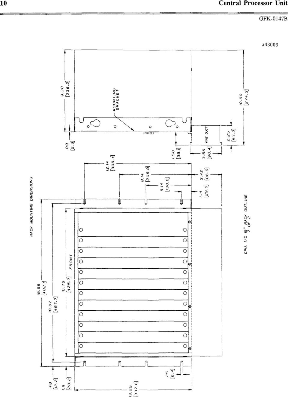
6 6 Central Processor Unit GF K-0 147B Installation This section provides a summary of the procedures described in Chapter 3 of the Series Six Pius User s Manual (GEK-96602). Do not attempt to install the Series Six Plus PLC without consulting that manual The Series Six Plus PLC can be rack, panel or wall mounted, depending on the position of the mounting brackets. IMPORTANT: Proper safety ground and signal ground connections must be made as described in the Series Six Plus User s Manual. Connect the Lithium-Manganese Dioxide battery to either of the male jacks beneath the battery on the Logic Memory module. Install the Logic Control module in slot 2, which is to the left of the I/O Control module. Use the extraction/insertion tool supplied with the basic CPU unit to insert (or remove) this module (or any other module) into the Series Six Plus rack. Install the Logic Memory module in slot 4, which is to the irnmediate left of the Arithmetic Control module. Use the extraction/insertion tool supplied with the CPU to insert this module into the Series Six Plus rack. Set the jumpers on the I/O Control module according to system requirements. 6. Make the following connections to the terminal block on the Series Six Plus PLC power supply: 3-wire (grounding) AC power cord for AC power supply DC source connections to POS and NEG terminal for DC power supply. Alarm relay contacts (optional) Auxiliary battery (optional) Install the protective cover plate after making these connections. Connect the cable from the primary I/O chain to the lower faceplate connector on the 1/O Control module. Connect the cable from the Workmaster computer or Program Development Terminal to the upper connector (Workmaster required with Expanded functions). If neither the Workmaster computer nor the PDT is to be connected, the upper connector can be left empty. NOTE After a power fault, the system comes back in the mode (STOP, RUN ENABLED, or RUN DISABLED) in which it was operating before power was lost. Both the RUN and the CHECK indicator can flash momentarily when power is turned on in the CPU. A valid RUN or CHECK state, however, is indicated by a steady glow of the LED. See outline drawings of racks on pages 7-10.

7

8

9

10
11 Central Processor Unit 11 GFK-0147B Table 2. SPECIFICATIONS Dimensions (19, 11 slots): Rack-Mount 19.0(W) x 13.4(H) x 9.3(D) inches (483 x 340 x 236 millimeters) Panel Mount 20,0(W) x 13.4(H) x 9.3(D) inches (508 x 340 x 236 millimeters) Dimensions (I3, 8 slots): Rack-Mount 16.0(W) x 13.4(H) x 9.3(D) inches (406 x 340 x 236 millimeters) Panel Mount (Brackets on sides) 16.0(W) x 13.4(H) x 9.3(D) inches (406 x 340 x 236 millimeters) Panel Mount (Brackets on Top and Bottom, Side by Side Mount) Weight (filled), 11 slot Storage Temperature Operating Temperature Humidity Power Requirements Allowable Power Interruptions Noise Immunity Memory Configuration (16.bit words) Input Capacity maximum Output Capacity maximum 13.25(W) x 16,15(H) x 9.3(D) inches (340 x 410 x 236 millimeters) 37 pounds (17 kg) -20 to +70C (-4 to +158F) 0 to +6OC (+32 to +140F) outside of rack 5% to 95% (non-condensing) Three power supplies are available: V ac Hz 250VA Max V dc 180 watts Max V dc 200 watts Max. 33 ms minimum at 115 V ac line 10 ms minimum at 20 V dc 4 ms minimum at 100 V dc Meets requirements of NEMA ICS and ANSI C 37.90A 5K total: 4K Logic Memory and 1K register Memory 12K total: 4K Logic Memory and 8K Register Memory 16K total: 8K Logic Memory and 8K Register Memory 24K total: 16K Logic Memory and 8K Register Memory 48K total: 32K Logic Memory and 16K Register Memory 80K total: 64K Logic Memory and 16K Register Memory points when in Expanded I/O mode points when in Expanded I/O mode Basic unit includes rack, power supply, I/O Control module, Arithmetic Control module, ribbon cable (connects Arithmetic Control to Logic Control), module extraction/insertion tool, mounting brackets, I/O termination plug, and field wiring trough.
 inches (406 x 340 x 236 millimeters) Panel Mount (Brackets on Top and Bottom, Side by Side Mount) Weight (filled), 11 slot Storage Temperature Operating Temperature Humidity Power Requirements")
12 12 Central Processor Unit - GFK-0 147B Table 3. ORDERING INSTRUCTIONS DESCRIPTION CATALOG NUMBER Series Six Plus CPU with 95 to 260 V ac Power Supply, 11 slot with 24 V dc Power Supply, 11 slot with 125 V dc Power Supply, 11 slot with 95 to 260 V ac Power Supply, 8 slot with 24 V dc Power Supply, 8 slot with 125 V dc Power Supply, 8 slot Logic Control Module (select one) Advanced Functions Expanded Functions Expanded II Functions Memory Options Total User Logic Register Memory Memory Memory 5K 4K 1K 12K 4K 8K 16K 8K 8K 24K 16K 8K 48K 32K 16K 80K 64K 16K Renewal Part IC6OOCP630 IC6OOCP634 IC6OOCP635 IC6OOCP610 IC6OOCP612 IC6OOCP615 IC6OOCB525 IC6OOCB526 IC600CB5 15 IC6OOLX605 ICBOOLX612 IC6OOLX616 IC6OOLX624 IC6OOLX648 IC6OOLX680 Series Six Plus CPU 8-slotrack without IC6OOCR610 power supply Series Six Plus CPU 11-slot rack without IC600CR620 power supply This symbol on the nameplate means the product is listed by Underwriters Laboratories Inc. (UL Standard No. 508, Industrial Control Equipment, subsection Electronic Power Conversion Equipment.) For further information, contact your local GE Fanuc North America Distributor or sales office. GE Fanuc Automation North America, Inc., Charlottesville, Virginia

Programming Logic controllers
 Programming Logic controllers Programmable Logic Controller (PLC) is a microprocessor based system that uses programmable memory to store instructions and implement functions such as logic, sequencing,
This Datasheet for the IC697CPM790. GMR Redundancy CPU, 486, 2K Triplex (voted) I/O. http://www.cimtecautomation.com/parts/p-14778-ic697cpm790.
 I/O. http://www.cimtecautomation.com/parts/p-14778-ic697cpm790.") his Datasheet for the GMR Redundancy CPU, 486, 2K riplex (voted) I/O. http://www.cimtecautomation.com/parts/p-14778-ic697cpm790.aspx Provides the wiring diagrams and installation guidelines for this GE
his Datasheet for the GMR Redundancy CPU, 486, 2K riplex (voted) I/O. http://www.cimtecautomation.com/parts/p-14778-ic697cpm790.aspx Provides the wiring diagrams and installation guidelines for this GE
JNIOR. Overview. Get Connected. Get Results. JNIOR Model 310. JNIOR Model 312. JNIOR Model 314. JNIOR Model 410
 The INTEG is an Ethernet I/O (digital, analog) device that monitors and controls a small set of process signals. functions as both basic I/O for integration with another application or system AND as a
EDI Distributor Control Interface Wiring and Setup Instructions
 Universal I/O EDI Distributor Control Interface Wiring and Setup Instructions EDI UNIVERSAL I/O INTERFACE MODULE The only interface needed for EDI-V5 controls Network compatible with all older EDI controls
L5354 ControlNet Communications Interface
 L5354 ControlNet Communications Interface Technical Manual HA470733 Issue 2 Copyright SSD Drives Inc 2005 All rights strictly reserved. No part of this document may be stored in a retrieval system, or
LTR Series Uninterruptible Power Systems 700 VA - 2.1 KVA. General Specification
 08/17/12 Rev2 LTR Series General Specification 700 VA to 2.1 KVA 1.0 General LTR Series Uninterruptible Power Systems 700 VA - 2.1 KVA General Specification This specification describes the features and
MACHINEMATE. CNC SYSTEM Hardware SPECIFICATION
 MACHINEMATE CNC SYSTEM Hardware SPECIFICATION Feb 2005 CONTENTS 1 Introduction / General... 3 1.1 Superior Capability in Technology and Productivity... 3 1.2 General hardware components... 4 1.3 Static
ECR Shelf System Installation Guide Centralized Rack Mount Call Recording
 Hardware & Installation Guide Algo Communication Products Ltd. Customer Support and Sales Tel: 1.877.884.2546 Fax: 604.437.5726 Email: [email protected] [email protected] www.algosolutions.com
Programmable Logic Controller PLC
 Programmable Logic Controller PLC UPCO ICAI Departamento de Electrónica y Automática 1 PLC Definition PLC is a user friendly, microprocessor based, specialized computer that carries out control functions
SIMATIC NET. CP 243-2 AS-Interface Master B C. Preface Contents. Technical Description and Installation Instructions Interface to the User Program
 Preface Contents SIMATIC NET CP 243-2 AS-Interface Master Manual Technical Description and Installation Instructions Interface to the User Program 2 in the S7-200 CPU Access to the Data of the AS-i Slaves
Programmable set for Ethernet Modbus/TCP in IP67 TI-BL67-PG-EN-2
 Type code Ident no. 1545065 Number of channels 2 Dimensions (W x L x H) 108 x 145 x 77.5 mm CoDeSys-programmable acc. to IEC 61131-3 Cable max. 50 m between interface and read/write head 10/100 Mbps Male
1 Application Description... 3. 1.1 Objective... 3 1.2 Goals... 3
 Contents Moxa Technical Support Team [email protected] 1 Application Description... 3 1.1 Objective... 3 1.2 Goals... 3 2 System Topology... 3 3 Hardware and Software Requirements... 4 4 Configuration...
is then retained absolutely without interruption.
 Page 1 of 11 DC UPS uninterruptible power supplies - DC UPS module 15 A Compact design, only 50 mm wide Absolutely interruption-free buffering of power failures through immediate electronic connection
SECTION 13421 PROGRAMMABLE LOGIC CONTROLLERS AND COMPUTER CONTROL SYSTEM PART 1 GENERAL. 1.01 Summary. A. Section Includes:
 SECTION 13421 PROGRAMMABLE LOGIC CONTROLLERS AND COMPUTER CONTROL SYSTEM PART 1 GENERAL 1.01 Summary A. Section Includes: 1. The ISS shall furnish all labor, materials, equipment, services and incidentals
Technical Training Module ( 30 Days)
") Annexure - I Technical Training Module ( 30 Days) Section 1 : Programmable Logic Controller (PLC) 1. Introduction to Programmable Logic Controller - A Brief History, Need and advantages of PLC, PLC configuration,
Annexure - I Technical Training Module ( 30 Days) Section 1 : Programmable Logic Controller (PLC) 1. Introduction to Programmable Logic Controller - A Brief History, Need and advantages of PLC, PLC configuration,
(Cat. No. 6008-SI) Product Data
 Product Data") (Cat. No. 6008-SI) Product Data 1 Because of the variety of uses for this product and because of the differences between solid state products and electromechanical products, those responsible for applying
(Cat. No. 6008-SI) Product Data 1 Because of the variety of uses for this product and because of the differences between solid state products and electromechanical products, those responsible for applying
MODEL 5010 DUAL CHANNEL SMOKE/FIRE DETECTION MODULE
 DESCRIPTION MODEL 5010 DUAL CHANNEL SMOKE/FIRE DETECTION MODULE DESCRIPTION The SST Model 5010 Two Channel Smoke/Fire Detection Module provides two independent detection input channels for the NOVA-5000
Non-Isolated Analog Voltage/Current Output module IC695ALG704 provides four configurable voltage or current output channels. Isolated +24 VDC Power
 July 2010 PACSystems* RX3i Non-Isolated Analog Output Module with HART Communications, IC695ALG728 Non-Isolated Analog Output Modules, IC695ALG704, IC695ALG708 MODULE OK FIELD STATUS TB IC695ALG708 Q1
TrueAlarm Fire Alarm Systems
 TrueAlarm Systems UL, ULC, CSFM Listed; FM Approved* Network Annunciators; es Features Provides a dedicated local area network (LAN) for connection of a TrueSite workstation server to remote clients: es
Industrial-Grade UPS System Heavy-duty power protection for harsh industrial environments
 Industrial-Grade UPS System Heavy-duty power protection for harsh industrial environments Model #: SM2000RMX Heavy-duty, industrial-grade metal housings Shock and vibration rated to MIL-STD-810D 19 inch
MAKING MODERN LIVING POSSIBLE. AK-SC255 On-Site Installation Guide DANFOSS ELECTRONIC CONTROLS & SENSORS
 MAKING MODERN LIVING POSSIBLE AK-SC255 On-Site Installation Guide DANFOSS ELECTRONIC CONTROLS & SENSORS How to Use This Guide Read this Guide completely as you install and start up your new AK-SC 255 controller.
AC-115 Compact Networked Single Door Controller. Installation and User Manual
 AC-115 Compact Networked Single Controller Installation and User Manual December 2007 Table of Contents Table of Contents 1. Introduction...5 1.1 Key Features... 6 1.2 Technical Specifications... 7 2.
Uninterruptible Power Supply
 96-01101 / rev. 2e / 2-2-12 Uninterruptible Power Supply EXCEPTIONAL SUPPORT & PROTECTION Uninterruptible Power Supply with Energy Saver design that is optimized to address the needs of A/V systems Features
SmartOnline 200-240V 5kVA 4.5kW On-Line Double-Conversion UPS, Extended Run, SNMP, Webcard, 4U Rack/Tower, USB, DB9 Serial
 SmartOnline 200-240V 5kVA 4.5kW On-Line Double-Conversion UPS, Extended Run, SNMP, Webcard, 4U Rack/Tower, USB, DB9 Serial MODEL NUMBER: SU5000RT4UHV Description Tripp Lite SU5000RT4UHV 5000VA / 5kVA /
Table of Contents. Creating a VC1000 Network... 3
 2 Table of Contents Creating a VC1000 Network... 3 Topology... 3 Unit ddressing... 4 Terminating Resistors... 5 Shielding... 5 Interconnecting the common... 6 ias Resistors... 6 VC1000 Hardware Configuration...
Setting Up and Testing the MAX Hardware
 Page 1 of 12 Setting Up and Testing the MAX Hardware This chapter covers these topics: Planning the hardware installation Inserting an expansion card Setting up the hardware Connecting to input power Connecting
Quick Installation. A Series of Intelligent Bar Code Reader with NeuroFuzzy Decoding. Quick Installation
 Quick Installation A Series of Intelligent Bar Code Reader with NeuroFuzzy Decoding This chapter intends to get your new FuzzyScan scanner working with your existing system within minutes. General instructions
Overview of Cisco 2600 Series Routers
 CHAPTER 1 Cisco 2600 series routers are modular access routers with LAN and WAN connections that can be configured by means of interchangeable modules and WAN interface cards. This guide discusses the
Internet Office UPS System Standby UPS for PCs, workstations and more
 Internet Office UPS System Standby UPS for PCs, workstations and more Model #: INTERNETOFFICE500 500VA standby tower UPS system Offers battery-derived AC output during blackouts and brownouts starting
Daker DK 1, 2, 3 kva. Manuel d installation Installation manual. Part. LE05334AC-07/13-01 GF
 Daker DK 1, 2, 3 kva Manuel d installation Installation manual Part. LE05334AC-07/13-01 GF Daker DK 1, 2, 3 kva Index 1 Introduction 24 2 Conditions of use 24 3 LCD Panel 25 4 Installation 28 5 UPS communicator
5-port / 8-port 10/100BaseTX Industrial Ethernet Switch User Manual
 5-port / 8-port 10/100BaseTX Industrial Ethernet Switch User Manual Content Overview... 1 Introduction... 1 Features... 3 Packing List... 4 Safety Precaution... 4 Hardware Description... 5 Front Panel...
Chapter 5 Cubix XP4 Blade Server
 Chapter 5 Cubix XP4 Blade Server Introduction Cubix designed the XP4 Blade Server to fit inside a BladeStation enclosure. The Blade Server features one or two Intel Pentium 4 Xeon processors, the Intel
How to read this guide
 How to read this guide The following shows the symbols used in this Quick start guide with descriptions and examples. Symbol Description Example P oint Reference Caution [ ] This symbol explains information
Remote Monitoring and REC 501 Control Unit Product Guide
 Remote Monitoring and Control Unit REC 501 Product Guide Issued: May 1999 Status: Updated Version: B/06.11.2001 Data subject to change without notice Features Remote control and monitoring unit for the
Model #: SMART2200CRMXL
 Tripp Lite 1111 West 35th Street Chicago, IL 60609 USA Telephone: +(773) 869 1234 E-mail: [email protected] Model #: SMART2200CRMXL SmartPro Compact Rackmount UPS System - Precision Protection for
1.44 kw Programmable DC Power Supplies XLN Series
 Data sheet 1.44 kw Programmable DC Power Supplies XLN Series New Family of High Density System Power Supplies The B&K Precision XLN series are compact, programmable, single-output DC power supplies, suitable
3500/22M Transient Data Interface
 3500/22M Transient Data Interface Bently Nevada* Asset Condition Monitoring Description The 3500 Transient Data Interface (TDI) is the interface between the 3500 monitoring system and GE s System 1* machinery
Memory Card (See note.)
") 1H/G-CPU@@H 1-series Programmable Controllers Indicators Inner Board Compartment An Inner Board can be mounted here. Peripheral Port The peripheral port connects Programming Devices, such as a Programming
1H/G-CPU@@H 1-series Programmable Controllers Indicators Inner Board Compartment An Inner Board can be mounted here. Peripheral Port The peripheral port connects Programming Devices, such as a Programming
User manual Compact Web PLC WP240 series IEC-line
 User manual Compact Web PLC WP240 series IEC-line update: 09-01-2014 IEC-line by OVERDIGIT overdigit.com 1. General description The WP240 device is a PLC, programmable in IEC61131-3 language using CoDeSys
DVPPF02-H2. PROFIBUS DP Slave Communication Module Application Manual
 DVPPF02-H2 PROFIBUS DP Slave Communication Module Application Manual Warning Please read this instruction carefully before use and follow this instruction to operate the device in order to prevent damages
Short Form Catalogue. Alarm Systems. Reliable Supervision and Control
 Short Form Catalogue Alarm Systems Reliable Supervision and Control Alarm Monitors and Indicators The SELCO product range includes a number of alarm monitors and indicator panels for use in numerous applications.
Electronic Control Devices The European Product Catalogue 2007
 FX14 Field Controller (1/4) FX14 Field Controller The FX14 is an equipment field controller in the Facility Explorer range of products. The controller is designed specifically for commercial Heating, Ventilating,
Series 427. 1/16 DIN Multi-Mode Bar Graph Display Timer TIMERS PRODUCT HIGHLIGHTS
 Series 427 1/16 DIN Multi-Mode Bar Graph Display Timer PRODUCT HIGHLIGHTS Digital Setting with 0.1% Accuracy Unique LED Bargraph Indicates Time Cycle in 20% Increments 8 Field Selectable Modes of Operation
CM705B - Universal Expander Module CM707B - Plug On Zone Expander Security Systems
 CM705B - Universal Expander Module CM707B - Plug On Zone Expander Security Systems EN Security System CM705B CM705B - Universal Expander Module The CM705B universal expander provides a cost effective way
MTS Power Products MIAMI FL 33142 ATS-22AG. Automatic Transfer Switch And Control PLC Operator s Manual
 MTS Power Products MIAMI FL 33142 ATS-22AG Automatic Transfer Switch And Control PLC Operator s Manual Dedicated Single Phase Transfer Switch With Touch Screen Controls Normal Power Connections Emergency
Programmable Terminal. NPSeries. Easy Setup with the Low-cost, Compact NP Series
 Programmable Terminal NPSeries Easy Setup with the Low-cost, Compact NP Series Simpler and More Versatile.OMRON s Compact NP Series Connect! Easier connection to OMRON PLCs and Temperature Controllers,
ABB RTU560A Series CMU & Modules
 ABB RTU560A Series CMU & Modules 1KGT 150 648 V1.02 March 4, 2012 Slide 1 Contents RTU560A rack solutions March 4, 2012 Slide 2 560CSR01 Available for wall mounting and swing frame Supports redundant power
FIREDEX 2200. Conventional Fire Panels
 68 Flexible, high specification system Choice of 1, 2, 4 or 8 zones Simple one-shot auto-reset user test facility Approved to EN54 Maintenance free poly switch circuit protection, with auto reset Class
2-Pair. Managed SHDSL Ethernet Extender. User s Manual
 2-Pair User s Manual 1. Quick Start Guide This quick start guide describes how to install and use the Managed SHDSL Ethernet Extender. This is the Ethernet Extender of choice to extend 10/100 Ethernet
FOSTCDR. Industrial Serial to Multimode Fiber Optic Converter PRODUCT INFORMATION B&B ELECTRONICS. Specifications Serial Technology
 FOSTCDR pn 8684R1 FOSTCDR-0812ds page 1/5 Industrial Serial to Multimode Fiber Optic Converter Data Rates up to 115.2 kbps 2.5 Mile (4 km) Range 10 to 30 VDC Input Voltage Wide Operating Temperature 2000V
Internet Office 750VA Ultra-compact Standby 120V UPS with USB port
 Internet Office 750VA Ultra-compact Standby 120V UPS with USB port MODEL NUMBER: INTERNET750U Highlights 750VA ultra-compact 120V standby UPS Maintains AC output during power failures 6 UPS battery supported
OPTICAL HEADEND PLATFORM OTOHP-NMS NETWORK MONITORING MODULE INSTRUCTION MANUAL
 OPTICAL HEADEND PLATFORM OTOHP-NMS NETWORK MONITORING MODULE INSTRUCTION MANUAL Phone: (209) 586-1022 (800) 545-1022 Fax: (209) 586-1026 OTOHP-NMS Rev. X1 E-Mail: [email protected] www.olsontech.com
PowerGem Pro Uninterruptible Power Supply
 Uninterruptible Power Supply User-friendly Intelligent Ultra reliable Range The Most Intelligent On-Line Double Conversion Power Protection System The range achieves higher reliability and greater immunity
ZC-24DO CANopen I/O Module: 24 Digital Outputs
 Z-PC Line EN ZC-24DO CANopen I/O Module: 24 Digital Outputs Installation Manual Contents: - General Specifications - Technical Specifications - Installation Rules - Electrical connections - DIP-switches
Programmable Logic Controllers
 Programmable Logic Controllers PLC Basics Dr. D. J. Jackson Lecture 2-1 Operating systems and application programs A PLC contains a basic operating system that allows for: Downloading and executing user
MCR1900 Media Converter 19-Slot Chassis
 MCR1900 Media Converter 19-Slot Chassis Installation Guide Part #5500304-11 Copyright Statement This document must not be reproduced in any way whatsoever, either printed or electronically, without the
MILLENIUM INSTALLATION MANUAL NTR 735 A. Simple Automation Control Module (MAS)
") MILLENIUM Table of contents 1. INTRODUCTION 1 2. HARDWARE DESCRIPTION 2 3. INSTALLATION 5 4. CONNECTION 6 5. USER SAFETY AND PROTECTION OF EQUIPMENT 8 1. Introduction The MILLENIUM series has been designed
MILLENIUM Table of contents 1. INTRODUCTION 1 2. HARDWARE DESCRIPTION 2 3. INSTALLATION 5 4. CONNECTION 6 5. USER SAFETY AND PROTECTION OF EQUIPMENT 8 1. Introduction The MILLENIUM series has been designed
1. SAFETY INFORMATION
 RS-232 Sound Level Meter 72-860A INSTRUCTION MANUAL www.tenma.com 1. SAFETY INFORMATION Read the following safety information carefully before attempting to operate or service the meter. Use the meter
SOLARCARE SERIES PRODUCT AND APPLICATION GUIDE
 SOLARCARE SERIES PRODUCT AND APPLICATION GUIDE for solar energy management LEATEC Delivering Solutions for Energy Management SOLAR ENERGY DATA CENTER BUILDING 4 to8 String Monitoring with 0.% Accuracy
HP UPS R1500 Generation 3
 HP UPS R1500 Generation 3 Installation Instructions Part Number 650952-001 NOTE: The rating label on the device provides the class (A or B) of the equipment. Class B devices have a Federal Communications
MICROSENS. Central 48 V DC Power Supplies for PoE-Components. Description. Features
 Central 48 V DC Power Supplies for PoE-Components MICROSENS Description Active network equipment which is supporting the Power-over-Ethernet functions, typically requires a powerful 48 V DC power supply.
CPU systron S 200 - S 250 - S 250c. systron S 200 - S 250 - S 250c. CPUs to the process modules. Stand-alone PLC
 E031019 000823 systron S 200 - S 250 - S 250c CPU systron S 200 - S 250 - S 250c 45 mm width Flexible and expandable Easy to use software for bus connection (S 250/ S 250c) CPUs to the process modules
Develop a Dallas 1-Wire Master Using the Z8F1680 Series of MCUs
 Develop a Dallas 1-Wire Master Using the Z8F1680 Series of MCUs AN033101-0412 Abstract This describes how to interface the Dallas 1-Wire bus with Zilog s Z8F1680 Series of MCUs as master devices. The Z8F0880,
MANUAL PC1000R [email protected]
 MANUAL PC1000R [email protected] Features The APart PC1000R is a professional multisource CD/USB/SD card music player, equipped with balanced and unbalanced analog outputs, coaxial and optical digital
Allen-Bradley/Rockwell
 MANUFACTURER DATA SHEET PLC-CPU Manufacturer: Allen-Bradley/Rockwell Model Number: SLC500 See www.geomartin.com for additional PDF datasheets Martin Part Number: E-014624-00 VendorPartNumber: 1747-L524
M1000 Process Alarm Monitor
 Data Sheet Process Alarm Monitor Reliable Supervision and Control 10 inputs with LED indications Supports both NO/NC input contacts 10 open collector outputs Built-in siren relay Text label for alarm descriptions
SmartPro 120V 2.2kVA 1.92kW Line-Interactive Sine Wave UPS, SNMP, Webcard option, 2U Rack/Tower, LCD, USB, DB9 Serial
 SmartPro 120V 2.2kVA 1.92kW Line-Interactive Sine Wave UPS, SNMP, Webcard option, 2U Rack/Tower, LCD, USB, DB9 Serial MODEL NUMBER: SMART2200RM2U Highlights 2.2kVA / 2200VA / 1920W line interactive 2U
Intelligent RS-485 I/O expansion unit: RU-87Pn Series
 INTRODUCTION RU-87Pn series is a remote intelligent I/O expansion unit that used to expand i-87k series I/O modules over the RS-485 for industrial monitoring and controlling applications. There are more
How To Control A Power Supply With A Mini Transmitter And Switch (Power Supply)
") transmitter (2 wire) / switch for continuous or On/Off Control Indication, monitoring, transmitting and continuous or On/Off control in one device Output signal 4...20 ma, 2-wire for continuous control
transmitter (2 wire) / switch for continuous or On/Off Control Indication, monitoring, transmitting and continuous or On/Off control in one device Output signal 4...20 ma, 2-wire for continuous control
USER MANUAL. VS-81H 8x1 HDMI Switcher MODEL: P/N: 2900-000670 Rev 4
 KRAMER ELECTRONICS LTD. USER MANUAL MODEL: VS-81H 8x1 HDMI Switcher P/N: 2900-000670 Rev 4 Contents 1 Introduction 1 2 Getting Started 2 2.1 Achieving the Best Performance 2 2.2 Safety Instructions 3
TAA-Compliant SmartPro 120V 1kVA.8kW Line-Interactive Sine Wave UPS, SNMP, Webcard, 1U Rack, USB, DB9 Serial
 TAA-Compliant SmartPro 120V 1kVA.8kW Line-Interactive Sine Wave UPS, SNMP, Webcard, 1U Rack, USB, DB9 Serial MODEL NUMBER: SM1000RM1UTAA Description Tripp Lite SM1000RM1UTAA 1000VA / 1kVA / 800 watt line
DCM. Product Brochure. Diagnostic Communication Master
 DCM Product Brochure Diagnostic Communication Master DCM The DCM Diagnostic Communication Master is the best solution for the control of actuators from a remote control room through a two-wire transmission-mode
Application. Characteristics RTU560. Data Sheet Communication Unit 560CMD11. Communication Unit 560CMD11
 Communication Unit 560CMD11 The SLC works as master for the RTU560 serial peripheral bus (I/O-Interface/ Wired-OR-Bus ). The MPU is responsible for the other tasks. The MPU handles the absolute time and
Series 90 * Programmable Coprocessor Module and Support Software. GE Intelligent Platforms. User s Manual. Programmable Control Products
 GE Intelligent Platforms Î Programmable Control Products Series 90 * Programmable Coprocessor Module and Support Software User s Manual GFK-0255K March 2010 GFL-002 Warnings, Cautions, and Notes as Used
3500/93 System Display
 3500/93 System Display Bently Nevada* Asset Condition Monitoring Description The 3500/93 System Display is designed to meet the requirements of American Petroleum Institute (API) Standard 670 and provide
Industrial RS-232/ RS-422/ RS-485 over Ethernet Media Converter
 ICS-2 S15 Industrial RS-232/ RS-422/ RS-485 over Ethernet Media Converter Cost Effective Solution for RS-232 / RS-422 / RS-485 to Industrial Ethernet Application PLANET ICS-210x series Smart Media Converter
Model #: SMART2200VS. 2200VA / 2.2kVA line interactive tower UPS. Maintains 120V nominal output over an input range of 79 to 147V
 SmartPro VS Tower UPS System Intelligent, line-interactive power management system Model #: SMART2200VS 2200VA / 2.2kVA line interactive tower UPS Maintains 120V nominal output over an input range of 79
zseries 18-Slot Chassis 18-Slot 3U PXI Express Chassis with AC Up to 8 GB/s
 TECHNICAL SPECIFICATIONS zseries 18-Slot Chassis 18-Slot 3U PXI Express Chassis with AC Up to 8 GB/s 2015 LitePoint, A Teradyne Company. All rights reserved. The LitePoint zseries 18-slot chassis is an
Chassis, Power Supply, and Element Management
 Chassis, Power Supply, and Element Management C-COR CHP Max5000 Converged Headend Platform Accelerate deployment of new, revenue generating advanced services Innovative technology creating converged high-
Automation System TROVIS 6400 TROVIS 6493 Compact Controller
 Automation System TROVIS 6400 TROVIS 6493 Compact Controller For panel mounting (front frame 48 x 96 mm/1.89 x 3.78 inch) Application Digital controller to automate industrial and process plants for general
Technical data. General specifications. Indicators/operating means. 30 Hz Multiplex operation 30 Hz / n, n = number of sensors, n 5
 Model Number Single head system Features Parameterization interface for the application-specific adjustment of the sensor setting via the service program ULTRA 000 programmable switch outputs Hysteresis
ENET-710. ENET-710 - Ethernet Module ENET-710 JAN / 06 FOUNDATION
 ENET-710 ENET-710 - Ethernet Module JAN / 06 ENET-710 FOUNDATION E N E T 7 1 0 ME smar www.smar.com Specifications and information are subject to change without notice. Up-to-date address information is
SECTION 13850 DETECTION AND ALARM
 SECTION 13850 DETECTION AND ALARM PART 1 GENERAL 1.01 SUMMARY A. Section Includes 1. Control Panel 2 Associated Equipment B. Products Installed But Not Supplied Under This Section 1. Section 16140 - Wiring
Quick Installation Guide. EtherFast 10/100M Switch. Model No.: SP624R. http://www.micronet.info
 Quick Installation Guide EtherFast 10/100M Switch Model No.: SP624R http://www.micronet.info Introduction Micronet SP624R 10/100M Switch provides powerful, high-performance Ethernet switch, with all ports
Designing an efficient Programmable Logic Controller using Programmable System On Chip
 Designing an efficient Programmable Logic Controller using Programmable System On Chip By Raja Narayanasamy, Product Apps Manager Sr, Cypress Semiconductor Corp. A Programmable Logic Controller (PLC) is
T7560A,B,C Digital Wall Module
 T7560A,B,C Digital Wall Module HONEYWELL EXCEL 5000 OPEN SYSTEM BEFORE INSTALLATION All wiring must comply with local electrical codes and ordinances or as specified on installation wiring diagrams. Digital
Part Number 129777-01 Revision A, January 1996. 3500 Monitoring System Rack Configuration and Utilities Guide
 Part Number 129777-01 Revision A, January 1996 3500 Monitoring System Rack Configuration and Utilities Guide Copyright 1995 Bently Nevada Corporation All Rights Reserved. No part of this publication may
Programmable Logic Controllers Definition. Programmable Logic Controllers History
 Definition A digitally operated electronic apparatus which uses a programmable memory for the internal storage of instructions for implementing specific functions such as logic, sequencing, timing, counting,
DL05 Memory Cartridge / Real Time Clock. Manual Number D0 01MC M
 DL05 Memory Cartridge / Real Time Clock Manual Number D0 01MC M WARNING Thank you for purchasing automation equipment from Automationdirect.com. We want your new DirectLOGIC automation equipment to operate
Digital I/O: OUTPUT: Basic, Count, Count+, Smart+
 Digital I/O: OUTPUT: Basic, Count, Count+, Smart+ The digital I/O option port in the 4-Series provides us with 4 optically isolated inputs and 4 optically isolated outputs. All power is supplied externally.
SmartPro 120V 1kVA 800W Line-Interactive Sine Wave UPS, SNMP, Webcard, 1U Rack, USB, DB9 Serial
 SmartPro 120V 1kVA 800W Line-Interactive Sine Wave UPS, SNMP, Webcard, 1U Rack, USB, DB9 Serial MODEL NUMBER: SMART1000RM1U Description Tripp Lite SMART1000RM1U 1000VA / 1kVA / 800 watt line interactive,
SmartPro 120V 750VA 600W Line-Interactive Sine Wave UPS, 1U Rackmount, SNMPWEBCARD Option, USB, DB9 Serial
 SmartPro 120V 750VA 600W Line-Interactive Sine Wave UPS, 1U Rackmount, SNMPWEBCARD Option, USB, DB9 Serial MODEL NUMBER: SMART750RM1U Highlights.75kVA / 750VA / 600W line interactive 1U rackmount UPS,
SmartPro 120V 750VA 600W Line-Interactive Sine Wave UPS, SNMP, Webcard, 1U Rack-Mount, USB, DB9 Serial
 SmartPro 120V 750VA 600W Line-Interactive Sine Wave UPS, SNMP, Webcard, 1U Rack-Mount, USB, DB9 Serial MODEL NUMBER: SMART750RM1U Highlights.75kVA / 750VA / 600W line interactive 1U rackmount UPS, Sine
SmartOnline Expandable Rack / Tower UPS System Online, double-conversion protection for mission critical applications
 SmartOnline Expandable Rack / Tower UPS System Online, double-conversion protection for mission critical applications Model #: SU3000RTXL3U 3000VA online 3U rack / tower UPS Enhanced serial communications
WaveReady CFM. Optical Link Monitoring System: Continuous Fiber Monitor
 WaveReady CFM Optical Link Monitoring System: Continuous Fiber Monitor www.lumentum.com Data Sheet The Lumentum Continuous Fiber Monitor (CFM) offers a compact, modular solution for performance monitoring
OVR Three-Phase Recloser and PCD Control Style Guide 1VAL264001-SG October 13, 2009 Revision F
 OVR Three-Phase Recloser and PCD Control Style Guide 1VAL264001-SG October 13, 2009 Revision F The OVR three-phase recloser style guide aids in the proper selection of your OVR three-phase style number.
Digital input modules
 8 172 TX-I/O Digital input modules TXM1.8D TXM1.16D Two fully compatible versions: TXM1.8D: 8 inputs, each with a three-color LED (green, yellow or red) TXM1.16D: As TXM1.8X, but 16 inputs, each with a
Modbus Communications for PanelView Terminals
 User Guide Modbus Communications for PanelView Terminals Introduction This document describes how to connect and configure communications for the Modbus versions of the PanelView terminals. This document
NGSS Data Consolidator (DC)
") NGSS Data Consolidator (DC) The Data Consolidator (DC) facilitates system configuration, monitors network status, and supervises long-term data storage and remote data transmission. The DC consists of
NGSS Data Consolidator (DC) The Data Consolidator (DC) facilitates system configuration, monitors network status, and supervises long-term data storage and remote data transmission. The DC consists of
Single channel data transceiver module WIZ2-434
 Single channel data transceiver module WIZ2-434 Available models: WIZ2-434-RS: data input by RS232 (±12V) logic, 9-15V supply WIZ2-434-RSB: same as above, but in a plastic shell. The WIZ2-434-x modules